EP3667641A1 - Vehicle driving assistance system, vehicle driving assistance method, and vehicle driving assistance program - Google Patents
Vehicle driving assistance system, vehicle driving assistance method, and vehicle driving assistance program Download PDFInfo
- Publication number
- EP3667641A1 EP3667641A1 EP18877551.4A EP18877551A EP3667641A1 EP 3667641 A1 EP3667641 A1 EP 3667641A1 EP 18877551 A EP18877551 A EP 18877551A EP 3667641 A1 EP3667641 A1 EP 3667641A1
- Authority
- EP
- European Patent Office
- Prior art keywords
- recommended
- marking
- speed
- vehicle
- route
- Prior art date
- Legal status (The legal status is an assumption and is not a legal conclusion. Google has not performed a legal analysis and makes no representation as to the accuracy of the status listed.)
- Withdrawn
Links
- 238000000034 method Methods 0.000 title claims description 34
- 230000001133 acceleration Effects 0.000 claims description 15
- 238000010586 diagram Methods 0.000 description 15
- 239000003086 colorant Substances 0.000 description 7
- 238000001514 detection method Methods 0.000 description 7
- 238000004364 calculation method Methods 0.000 description 6
- 230000007423 decrease Effects 0.000 description 5
- 230000000694 effects Effects 0.000 description 3
- 238000004891 communication Methods 0.000 description 2
- 230000015572 biosynthetic process Effects 0.000 description 1
- 230000001149 cognitive effect Effects 0.000 description 1
- 230000003287 optical effect Effects 0.000 description 1
- 238000009877 rendering Methods 0.000 description 1
Images


Classifications
-
- G—PHYSICS
- G01—MEASURING; TESTING
- G01C—MEASURING DISTANCES, LEVELS OR BEARINGS; SURVEYING; NAVIGATION; GYROSCOPIC INSTRUMENTS; PHOTOGRAMMETRY OR VIDEOGRAMMETRY
- G01C21/00—Navigation; Navigational instruments not provided for in groups G01C1/00 - G01C19/00
- G01C21/26—Navigation; Navigational instruments not provided for in groups G01C1/00 - G01C19/00 specially adapted for navigation in a road network
- G01C21/34—Route searching; Route guidance
- G01C21/36—Input/output arrangements for on-board computers
- G01C21/3626—Details of the output of route guidance instructions
- G01C21/365—Guidance using head up displays or projectors, e.g. virtual vehicles or arrows projected on the windscreen or on the road itself
-
- B—PERFORMING OPERATIONS; TRANSPORTING
- B60—VEHICLES IN GENERAL
- B60K—ARRANGEMENT OR MOUNTING OF PROPULSION UNITS OR OF TRANSMISSIONS IN VEHICLES; ARRANGEMENT OR MOUNTING OF PLURAL DIVERSE PRIME-MOVERS IN VEHICLES; AUXILIARY DRIVES FOR VEHICLES; INSTRUMENTATION OR DASHBOARDS FOR VEHICLES; ARRANGEMENTS IN CONNECTION WITH COOLING, AIR INTAKE, GAS EXHAUST OR FUEL SUPPLY OF PROPULSION UNITS IN VEHICLES
- B60K35/00—Arrangement of adaptations of instruments
-
- B60K35/23—
-
- B60K35/28—
-
- B—PERFORMING OPERATIONS; TRANSPORTING
- B60—VEHICLES IN GENERAL
- B60R—VEHICLES, VEHICLE FITTINGS, OR VEHICLE PARTS, NOT OTHERWISE PROVIDED FOR
- B60R21/00—Arrangements or fittings on vehicles for protecting or preventing injuries to occupants or pedestrians in case of accidents or other traffic risks
-
- B—PERFORMING OPERATIONS; TRANSPORTING
- B60—VEHICLES IN GENERAL
- B60W—CONJOINT CONTROL OF VEHICLE SUB-UNITS OF DIFFERENT TYPE OR DIFFERENT FUNCTION; CONTROL SYSTEMS SPECIALLY ADAPTED FOR HYBRID VEHICLES; ROAD VEHICLE DRIVE CONTROL SYSTEMS FOR PURPOSES NOT RELATED TO THE CONTROL OF A PARTICULAR SUB-UNIT
- B60W50/00—Details of control systems for road vehicle drive control not related to the control of a particular sub-unit, e.g. process diagnostic or vehicle driver interfaces
- B60W50/08—Interaction between the driver and the control system
- B60W50/14—Means for informing the driver, warning the driver or prompting a driver intervention
-
- G—PHYSICS
- G01—MEASURING; TESTING
- G01C—MEASURING DISTANCES, LEVELS OR BEARINGS; SURVEYING; NAVIGATION; GYROSCOPIC INSTRUMENTS; PHOTOGRAMMETRY OR VIDEOGRAMMETRY
- G01C21/00—Navigation; Navigational instruments not provided for in groups G01C1/00 - G01C19/00
- G01C21/10—Navigation; Navigational instruments not provided for in groups G01C1/00 - G01C19/00 by using measurements of speed or acceleration
-
- G—PHYSICS
- G01—MEASURING; TESTING
- G01C—MEASURING DISTANCES, LEVELS OR BEARINGS; SURVEYING; NAVIGATION; GYROSCOPIC INSTRUMENTS; PHOTOGRAMMETRY OR VIDEOGRAMMETRY
- G01C21/00—Navigation; Navigational instruments not provided for in groups G01C1/00 - G01C19/00
- G01C21/26—Navigation; Navigational instruments not provided for in groups G01C1/00 - G01C19/00 specially adapted for navigation in a road network
- G01C21/34—Route searching; Route guidance
- G01C21/36—Input/output arrangements for on-board computers
- G01C21/3626—Details of the output of route guidance instructions
- G01C21/3647—Guidance involving output of stored or live camera images or video streams
-
- G—PHYSICS
- G06—COMPUTING; CALCULATING OR COUNTING
- G06V—IMAGE OR VIDEO RECOGNITION OR UNDERSTANDING
- G06V20/00—Scenes; Scene-specific elements
- G06V20/50—Context or environment of the image
- G06V20/56—Context or environment of the image exterior to a vehicle by using sensors mounted on the vehicle
- G06V20/58—Recognition of moving objects or obstacles, e.g. vehicles or pedestrians; Recognition of traffic objects, e.g. traffic signs, traffic lights or roads
-
- G—PHYSICS
- G08—SIGNALLING
- G08G—TRAFFIC CONTROL SYSTEMS
- G08G1/00—Traffic control systems for road vehicles
- G08G1/16—Anti-collision systems
-
- B60K2360/165—
-
- B60K2360/166—
-
- B60K2360/167—
-
- B60K2360/174—
-
- B60K2360/177—
-
- B60K2360/347—
-
- B60K2360/785—
-
- B60K35/60—
-
- B—PERFORMING OPERATIONS; TRANSPORTING
- B60—VEHICLES IN GENERAL
- B60W—CONJOINT CONTROL OF VEHICLE SUB-UNITS OF DIFFERENT TYPE OR DIFFERENT FUNCTION; CONTROL SYSTEMS SPECIALLY ADAPTED FOR HYBRID VEHICLES; ROAD VEHICLE DRIVE CONTROL SYSTEMS FOR PURPOSES NOT RELATED TO THE CONTROL OF A PARTICULAR SUB-UNIT
- B60W50/00—Details of control systems for road vehicle drive control not related to the control of a particular sub-unit, e.g. process diagnostic or vehicle driver interfaces
- B60W50/08—Interaction between the driver and the control system
- B60W50/14—Means for informing the driver, warning the driver or prompting a driver intervention
- B60W2050/146—Display means
-
- Y—GENERAL TAGGING OF NEW TECHNOLOGICAL DEVELOPMENTS; GENERAL TAGGING OF CROSS-SECTIONAL TECHNOLOGIES SPANNING OVER SEVERAL SECTIONS OF THE IPC; TECHNICAL SUBJECTS COVERED BY FORMER USPC CROSS-REFERENCE ART COLLECTIONS [XRACs] AND DIGESTS
- Y02—TECHNOLOGIES OR APPLICATIONS FOR MITIGATION OR ADAPTATION AGAINST CLIMATE CHANGE
- Y02T—CLIMATE CHANGE MITIGATION TECHNOLOGIES RELATED TO TRANSPORTATION
- Y02T10/00—Road transport of goods or passengers
- Y02T10/80—Technologies aiming to reduce greenhouse gasses emissions common to all road transportation technologies
- Y02T10/84—Data processing systems or methods, management, administration
Definitions
- the present invention relates to a vehicle driving assistance technique for assisting in driving of a vehicle by a driver.
- JP 2017-33542 A discloses an information display device that displays a travel route for allowing a vehicle to travel while avoiding obstacles present around the vehicle, such that the travel route is superimposed on a view seen from a driver's seat through a windshield (claim 1, FIGS. 5 to 8 , etc.). A driver can appropriately check the travel route that the vehicle can travel while avoiding contact with the obstacles.
- JP 2017-33542 A exemplifies that a vehicle performs deceleration control by receiving a brake signal of a vehicle in front of the vehicle by vehicle-to-vehicle communication.
- obstacles are not always vehicles having a vehicle-to-vehicle communication function, and are often people, bicycles, and other objects. Therefore, there is still room for improvement in terms of informing the driver about an appropriate travel speed and travel route so that various obstacles present around the vehicle can be avoided.
- Patent Literature 1 JP 2017-33542 A
- a characteristic configuration of a vehicle driving assistance system in view of the above description is that the vehicle driving assistance system includes a display part that displays a recommended driving marking superimposed on a real view, the recommended driving marking includes: a recommended route marking representing a recommended route, the recommended route being a traveling route with a relatively low likelihood of interference with one or a plurality of obstacles present in a traveling direction of a vehicle; and a recommended speed marking representing a recommended speed index, the recommended speed index being an index related to a travel speed recommended when the vehicle travels the recommended route, and the recommended route marking and the recommended speed marking are displayed so as to be associated with each other.
- the vehicle driving assistance method can have various steps having features of the above-described vehicle driving assistance system.
- the vehicle driving assistance program can cause a computer to implement various functions having the features of the above-described vehicle driving assistance system.
- these vehicle driving assistance method and vehicle driving assistance program can also provide the functions and effects of the above-described vehicle driving assistance system.
- a characteristic configuration of a vehicle driving assistance method in that case is that the vehicle driving assistance method displays, on a display part, a recommended driving marking superimposed on a real view, the recommended driving marking includes: a recommended route marking representing a recommended route, the recommended route being a traveling route with a relatively low likelihood of interference with one or a plurality of obstacles present in a traveling direction of a vehicle; and a recommended speed marking representing a recommended speed index, the recommended speed index being an index related to a travel speed recommended when the vehicle travels the recommended route, and the vehicle driving assistance method includes a step of displaying the recommended route marking and the recommended speed marking such that the recommended route marking and the recommended speed marking are associated with each other.
- a characteristic configuration of a vehicle driving assistance program is that the vehicle driving assistance program displays, on a display part, a recommended driving marking superimposed on a real view, the recommended driving marking includes: a recommended route marking representing a recommended route, the recommended route being a traveling route with a relatively low likelihood of interference with one or a plurality of obstacles present in a traveling direction of a vehicle; and a recommended speed marking representing a recommended speed index, the recommended speed index being an index related to a travel speed recommended when the vehicle travels the recommended route, and the vehicle driving assistance program causes a computer to implement a function of displaying the recommended route marking and the recommended speed marking such that the recommended route marking and the recommended speed marking are associated with each other.
- the driver by displaying a recommended driving marking in which a recommended route marking is associated with a recommended speed marking, the driver can be appropriately informed in an easy-to-understand manner about information on what travel speed is appropriate for traveling a recommended route.
- the driver can be appropriately informed about information on a route, a speed, etc., recommended for traveling while avoiding obstacles present around the vehicle.
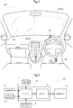
- FIG. 1 shows an example of an area near a driver's seat 101 of a vehicle 100 having a vehicle driving assistance system mounted thereon
- a block diagram of FIG. 2 schematically shows an example of a system configuration of a vehicle driving assistance system 10.
- FIG. 3 shows a concept of driving assistance provided by the vehicle driving assistance system 10
- a flowchart of FIG. 4 shows an example of a procedure of driving assistance which is implemented as, for example, a vehicle driving assistance method and a vehicle driving assistance program.
- FIGS. 5 to 7 show examples of a recommended driving marking M superimposed on a real view S.
- the vehicle driving assistance system 10 is a system that provides a driver with information for assisting in driving.
- the vehicle driving assistance system 10 displays a recommended driving marking M superimposed on a real view S.
- the vehicle driving assistance method is a method for providing driving assistance by using, for example, hardware and software that form the vehicle driving assistance system 10 such as those which will be described later with reference to FIG. 2 , etc.
- the vehicle driving assistance program is a program that is executed on, for example, a computer (e.g., an arithmetic processing unit 4 which will be described later with reference to FIG. 2 ) included in the vehicle driving assistance system 10, to implement a vehicle driving assistance function.
- a real view S on which a recommended driving marking M is superimposed may be a view seen from the driver's seat 101 through a windshield 50 of the vehicle 100, or may be video that is shot by a front camera 1 (see FIGS. 2 and 3 , etc.) which will be described later, and shown on a monitor 52.
- the recommended driving marking M is, for example, rendered on a head-up display 51 which is formed on the windshield 50, and superimposed on the real view S.
- a dashed-line region shown in the windshield 50 in FIG. 1 is a region in which the head-up display 51 is formed.
- the recommended driving marking M is superimposed on the video.
- the vehicle driving assistance system 10 includes the front camera 1 (CAMERA), an arithmetic processing device 2 (CAL), a graphic control unit 3 (GCU), and a display device 5 (DISPLAY).
- the arithmetic processing device 2 and the graphic control unit 3 are formed as a single processor (a system LSI, a digital signal processor (DSP), etc.) or as a part of the arithmetic processing unit 4 which is formed as a single electronic control unit (ECU).
- the arithmetic processing unit 4 may include other functional parts which are not shown.
- the display device 5 (display part) includes the above-described head-up display 51 and monitor 52.
- the vehicle driving assistance system 10 further includes a sensor group 6 (SEN), a navigation database 7 (navi_db), and an eyepoint detection device 8 (EP_DTCT).
- the sensor group 6 can include sonar, radar, a vehicle speed sensor, a yaw-rate sensor, a global positioning system (GPS) receiver, etc.
- the navigation database 7 is a database that stores map information, road information, and ground object information (information on traffic signs, road markings, facilities, etc.).
- the eyepoint detection device 8 is configured to include, for example, a camera that shoots a driver's head, and detects a driver's eyepoint (eyes). It is preferable that a recommended driving marking M which is rendered on the head-up display 51 be rendered at a location appropriate to the driver's eyepoint.
- the arithmetic processing device 2 identifies one or a plurality of obstacles B present around the vehicle 100, particularly, present close to a traveling direction, by image recognition that uses shot images obtained by the front camera 1. At this time, by further using information provided from the sensor group 6 such as sonar and radar, recognition accuracy may be able to be improved.
- the arithmetic processing device 2 creates a recommended driving marking M including a recommended route marking MK (see FIG. 5 , etc.) representing a recommended route K (see FIG. 3 ) which is a traveling route with a relatively low likelihood of interference with obstacles B; and a recommended speed marking MV (see FIG.
- a recommended speed index which is an index related to a travel speed recommended when the vehicle 100 travels the recommended route K.
- a recommended driving marking M by using information provided from the sensor group 6 such as a vehicle speed sensor, a yaw-rate sensor, and a GPS receiver, creation accuracy may be able to be improved.
- the vehicle driving assistance system 10 determines that as shown in FIG. 3 , an obstacle B present in a traveling direction of the vehicle 100 and the vehicle 100 are likely to interfere with each other, the vehicle driving assistance system 10 calculates a traveling route with a relatively low likelihood of interference with the obstacle B, as a recommended route K.
- the vehicle driving assistance system 10 first obtains shot images of views in a traveling direction of the vehicle 100 which are shot by the front camera 1 (#1: a shot image obtaining step and a shot image obtaining function).
- the vehicle driving assistance system 10 recognizes images of obstacles B with which the vehicle 100 is likely to interfere, from among the shot images (#2: an obstacle recognition step and an obstacle recognition function).
- the obstacles B may be detected not only by image recognition, but also by using other methods that use results of detection by the sensor group 6. Therefore, the obstacle recognition step can also be referred to as obstacle detection step.
- the vehicle driving assistance system 10 calculates a recommended route K which is a traveling route with a relatively low likelihood of interference with the obstacles B, and a recommended speed index at which the vehicle 100 travels the recommended route K (#4: a recommended route calculation step and a recommended route calculation function).
- a recommended route K and a recommended speed index be calculated taking also into account a road width, whether there is an intersection, etc.
- FIG. 4 exemplifies a mode in which prior to the recommended route calculation step #4, a database reference step #3 (database reference function) at which information in the navigation database 7 is referred to is performed.
- the vehicle driving assistance system 10 determines, based on the obstacles B recognized or detected, whether the obstacles B influence a traveling route of the vehicle 100.
- a traveling route of the vehicle 100 As one mode, in a range in which the vehicle 100 can travel in the traveling direction (e.g., on a road), costs related to the traveling are calculated. For example, the cost is high for a location where an obstacle B is present and an area around the obstacle B, and the cost is low for a location where there is no obstacle B, etc., and thus the vehicle 100 can travel smoothly.
- a destination on the traveling route is set in a range of a shot image, and the cost of the destination is set to the lowest value (e.g., zero).
- the vehicle driving assistance system 10 can calculate a recommended route K by calculating the shortest course that passes through low-cost points from a current location to a destination. In this calculation method, a route in a direction with low costs is calculated, and thus, a calculation load becomes comparatively light. Note that there is also a case in which there are a large number of obstacles B and thus it is better for the vehicle 100 to stop. To handle such a case, it is preferable that an upper limit of costs at which a route can be shut down be also set.
- a potential method for a technique for thus performing autonomous operation while avoiding obstacles B in a three-dimensional space, there is known, for example, a potential method.
- the potential method is publicly known and thus a detailed description thereof is omitted, but, for example, by defining potential functions for a current value, a target location (destination), and an obstacle B and setting a gradient of the potential functions as a traveling direction, a recommended route K can be calculated.
- the gradient can be found by a partial derivative for each coordinate component (e.g., for each of x-, y-, and z-axes in a three-dimensional Cartesian coordinate system.).
- a potential gradient to the destination value acts in an attractive direction, and a traveling direction of the recommended route K goes toward the destination value.
- a potential gradient of the obstacle B acts in a repulsive direction
- the recommended route K is set so as to avoid the obstacle B.
- the potential functions can be updated in real time based on observation information (shot images, results of detection by the sensor group 6, etc.), by which an appropriate recommended route K at each point in time can be calculated.
- the vehicle driving assistance system 10 When the vehicle driving assistance system 10 has calculated a recommended route K and a recommended speed index, the vehicle driving assistance system 10 creates a recommended driving marking M including a recommended route marking MK and a recommended speed marking MV, and outputs the recommended driving marking M to the display device 5 (#5: a marking creation step (marking creation function) and #6: a marking output step (marking output function)).
- the recommended route marking MK and the recommended speed marking MV are associated with each other.
- the recommended route K and the recommended speed index may be separately calculated, but it is preferable to create, at the marking creation step #5, a recommended driving marking M such that the recommended route K is associated with the recommended speed index.
- the marking creation step #5 (marking creation function) is a step (function) of associating the recommended route marking MK with the recommended speed marking MV.
- the recommended driving marking M is outputted such that the recommended driving marking M is displayed appropriate to the locations of obstacles B in a real view S.
- the marking output step #6 marking output function
- the marking output step #6 is a step (function) of displaying the recommended driving marking M, appropriate to the locations of obstacles B in a real view S.
- the vehicle driving assistance method is a method for implementing driving assistance by performing each step such as those described above, using hardware and software that form the vehicle driving assistance system 10.
- a computer e.g., the arithmetic processing unit 4 which will be described later with reference to FIG. 2
- the vehicle driving assistance system 10 executes a program that implements each function such as those described above.
- FIGS. 5 to 7 show examples of a recommended driving marking M superimposed on a real view S.
- the recommended driving marking M is displayed appropriate to the locations of obstacles B in the real view S, and can appropriately provide guidance on how the driver should drive the vehicle 100 in relation to the obstacles B. That is, since the recommended driving marking M is displayed appropriate to the locations of obstacles B in the real view S, the driver can also easily understand the reason why a travel route, a travel speed, etc., are thus recommended.
- a recommended route marking MK and a recommended speed marking MV are displayed so as to be associated with each other. Specifically, the recommended speed marking MV is displayed in a display region of the recommended route marking MK
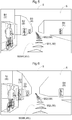
- FIG. 5 exemplifies a real view S and a recommended driving marking M for a case in which the vehicle 100 is present approximately at a location indicated by solid lines in FIG. 3 .
- the vehicle driving assistance system 10 has detected the presence of obstacles B in portions enclosed by dashed lines in FIG. 5 .
- a first obstacle B1 is a person riding on a bicycle, and a second obstacle B2, a third obstacle B3, and a fourth obstacle B4 are persons walking.
- each obstacle B is a moving dynamic obstacle.
- the vehicle driving assistance system 10 detects the presence of obstacles B based on shot images of the front camera 1.
- an obstacle B is a dynamic obstacle
- a moving path of the dynamic obstacle is detected using, for example, a publicly known image recognition process such as an optical flow method, based on shot images of the front camera 1, by which a future moving direction is predicted (estimated).
- the thus estimated moving direction is referred to as estimated moving direction.
- an arrow indicated by a dash-dotted line extending from the obstacle B in FIG. 3 indicates an estimated moving direction of the obstacle B.
- the vehicle driving assistance system 10 calculates influence exerted on the traveling of the vehicle 100 by an obstacle B (including a dynamic obstacle), based on a location where the obstacle B is present and an estimated moving direction of the obstacle B.
- FIG. 3 exemplifies influence E calculated for the obstacle B.
- the influence E is set in a stepwise manner, and first influence E1 in a region close to the obstacle B is greater influence E than second influence E2 in a region relatively far from the obstacle B.
- first influence E1 in a region close to the obstacle B is greater influence E than second influence E2 in a region relatively far from the obstacle B.
- the vehicle driving assistance system 10 sets a recommended route K so as to avoid a region as much as possible in which the obstacle B is estimated to influence the traveling of the vehicle 100 (e.g., a region in which the first influence E1 and the second influence E2 are estimated). That is, a traveling route with a relatively low likelihood of interference between the obstacle B present in a traveling direction of the vehicle 100 and the vehicle 100 is set as a recommended route K.
- FIG. 5 exemplifies a mode in which the recommended route K thus set is superimposed on the real view S, as a recommended route marking MK
- the recommended route marking MK is displayed appropriate to the locations of the obstacles B in the real view S.
- the recommended route K that the vehicle 100 can travel with appropriate spacing between the first obstacle B1 and the second obstacle B2 and the vehicle 100 is shown to the driver as the recommended route marking MK.
- the recommended route marking MK is displayed so as to be associated with a recommended speed marking MV.
- the recommended speed marking MV is displayed in a display region of the recommended route marking MK, and is displayed as a recommended driving marking M in which the recommended speed marking MV is integrated with the recommended route marking MK
- the recommended driving marking M (recommended route marking MK) is formed by arranging a plurality of unit markings UM along the recommended route K.
- the recommended speed marking MV is represented by making the colors of the unit markings UM arranged side by side along the recommended route K different from each other.
- the vehicle 100 In the traveling direction of the vehicle 100, the vehicle 100 is likely to approach the first obstacle B1 and the second obstacle B2, and thus, it is desirable that the vehicle 100, for example, slow down. Hence, the recommended speed of the vehicle 100 decreases in the traveling direction.
- unit markings UM arranged on a driver side are displayed using first unit markings M1 (e.g., white or blue), and unit markings UM arranged on a traveling direction side are displayed using second unit markings M2 (e.g., yellow).
- first unit markings M1 e.g., white or blue
- second unit markings M2 e.g., yellow
- the colors of the first unit marking M1 and the second unit marking M2 be colors that call more attention for a lower recommended speed, based on cognitive engineering, etc. Compared to the white or blue used for the first unit markings M1, the yellow used for the second unit markings M2 generally reminds a person of the necessity for more attention.
- the recommended speed marking MV is displayed so as to be associated with the recommended route marking MK by displaying a recommended speed index for each point on the recommended route K. For example, the travel speed recommended for the vehicle 100 varies from point to point on the recommended route K. By displaying a recommended speed index for each point on the recommended route K such that the recommended speed index is associated with the recommended route marking MK, the driver can be informed in an easy-to-understand manner about information on what travel speed is appropriate for traveling the recommended route K.
- FIG. 6 exemplifies a recommended driving marking M for a case in which the vehicle 100 has further traveled ahead compared to in FIG. 5 .
- the third obstacle B3 and the fourth obstacle B4 are also closer in distance to the vehicle 100.
- the colors of the unit markings UM all become the color for the second unit markings M2, recommending slowing down of the vehicle 100.
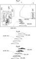
- FIG. 7 exemplifies a recommended driving marking M for a case in which the vehicle 100 has further traveled ahead compared to in FIG. 6 .
- the first obstacle B1 and the fourth obstacle B4 approach the route that the vehicle 100 travels.
- third unit markings M3 e.g., red
- the third unit markings M3 are applied in a case of a recommended speed at which going at the slowest possible speed or a stop is recommended.
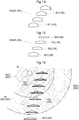
- a mode in which the recommended speed marking MV is displayed in different colors depending on a travel speed (one of recommended speed indices which will be described later) recommended for the vehicle 100 is exemplified and described with reference to FIGS. 5 to 7 . That is, when the vehicle 100 can travel at a travel speed with no particular constraints, as shown in FIG. 8 , the entire recommended route K is formed of first unit markings M1 (white or blue). On the other hand, when the travel speed decreases as traveling the recommended route K, as shown in FIG. 9 , unit markings UM are arranged such that a first unit marking M1 and then second unit markings M2 (yellow) are arranged, followed by third unit markings M3 (red).
- FIGS. 5 to 9 exemplify a mode in which color gradation is represented by arranging unit markings UM with different colors along a recommended route K
- a mode is not limited thereto.
- a mode may be adopted in which a recommended route marking MK is formed in a continuous linear form, and the color changes in the single continuous marking.
- the recommended speed marking MV not only adopts a mode in which the color of the recommended driving marking M thus varies, but may also be such that a mode in which the unit markings UM are arranged varies.
- the recommended speed marking MV can adopt a mode in which the recommended speed marking MV is displayed in a manner in which at least one of the color, shape, and movement of the recommended driving marking M varies depending on a recommended speed index such as a travel speed. Such a mode will be described below with reference to FIGS. 10 to 15 .
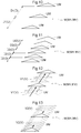
- FIGS. 10 and 11 exemplify a mode in which a recommended speed marking MV is represented by making an arrangement mode of a plurality of unit markings UM vary. That is, a mode is exemplified in which a recommended speed marking MV is displayed by making intervals D with which a plurality of unit markings UM are arranged vary depending on a recommended speed index such as a travel speed.
- FIG. 10 shows a case in which the vehicle 100 can travel at a travel speed with no particular constraints, and unit markings UM are arranged with first intervals D1 along a recommended route K.
- FIG. 11 exemplifies a recommended speed marking MV for a case in which the vehicle 100 is allowed to travel at a lower travel speed than that in FIG.
- unit markings UM are arranged with second intervals D2 shorter than the first intervals D1 along the recommended route K.
- the spacing D between unit markings UM as a distance at which the vehicle 100 travels in a unit of time, in a case of the second intervals D2 which are shorter intervals D, the travel speed of the vehicle 100 is low, enabling to prompt the driver to drive slowly.
- FIGS. 12 and 13 exemplify a mode in which a recommended speed marking MV is displayed in a manner in which the movement of the recommended speed marking MV varies depending on a recommended speed index such as the travel speed of the vehicle 100.
- the recommended speed marking MV is represented by making a moving speed V at which unit markings UM move in a traveling direction along a recommended route K vary depending on a recommended speed index such as a travel speed.
- FIG. 12 shows a case in which the vehicle 100 can travel at a travel speed with no particular constraints, and unit markings UM move in a traveling direction of the vehicle 100 at a first speed V1 along a recommended route K.
- FIG. 12 shows a case in which the vehicle 100 can travel at a travel speed with no particular constraints, and unit markings UM move in a traveling direction of the vehicle 100 at a first speed V1 along a recommended route K.
- a recommended speed marking MV for a case in which the vehicle 100 is allowed to travel at a lower travel speed than that in FIG. 12 , and unit markings UM move in the traveling direction of the vehicle 100 at a second speed V2 lower than the first speed V1 along the recommended route K.
- the moving speed of the unit markings UM as the travel speed of the vehicle 100, in a case of the second speed V2 which is a lower moving speed V, the travel speed of the vehicle 100 is low, enabling to prompt the driver to drive slowly.
- FIGS. 12 and 13 exemplify a mode in which the movement (moving speed V) of the recommended speed marking MV is represented by allowing each of a plurality of unit markings UM to move
- a mode is not limited thereto.
- a single recommended route marking MK may move along a recommended route K, or a mode in which a continuous linear recommended route marking MK sweeps (a mode in which the recommended route marking MK disappears in turn from the driver side and when it reaches an end of the recommended route K, rendering is performed again, which is repeated) may be adopted.
- FIGS. 14 and 15 exemplify a mode in which a recommended speed marking MV is displayed in a manner in which the shape of the recommended speed marking MV varies depending on a recommended speed index such as the travel speed of the vehicle 100.
- FIGS. 14 and 15 exemplify a mode in which the shapes of unit markings UM vary depending on a recommended speed index.
- FIG. 14 shows a case in which the vehicle 100 can travel at a travel speed with no particular constraints.
- Unit markings UM are formed by arranging first unit markings M1 having the same shape along a recommended route K, and by the side-by-side arrangement of the first unit markings M1 having the same shape, a recommended speed marking MV is displayed.
- FIG. 15 exemplifies a recommended speed marking MV for a case in which the vehicle 100 is allowed to travel at a lower travel speed than that in FIG. 14 .
- Unit markings UM include a second unit marking M2 having a shape indicating that the travel speed is lower than that of the first unit marking M1; a third unit marking M3 representing a travel speed lower than that of the second unit marking M2; and a fourth unit marking M4 representing a travel speed lower than that of the third unit marking M3.
- Each unit marking UM is formed such that the angle (interior angle) of a top edge portion going in a traveling direction increases as the travel speed decreases.
- a top edge portion of the second unit marking M2 has a larger angle than a top edge portion of the first unit marking M1
- a top edge portion of the third unit marking M3 has a larger angle than the top edge portion of the second unit marking M2.
- a top edge portion of the fourth unit marking M4 has a larger angle than the top edge portion of the third unit marking M3, and the fourth unit marking M4 has a linear top edge portion.
- the maximum value of the angle (interior angle) of the top edge portion of the unit marking UM is 180 degrees.
- the first unit marking M1, the second unit marking M2, and the third unit marking M3 are formed in a pentagon shape so as to remind the driver of an arrow indicating a traveling direction, whereas the fourth unit marking M4 is formed in a rectangular shape with no arrow portion.
- the fourth unit marking M4 can serve as a recommended speed marking MV that recommends stopping of the vehicle 100.
- FIGS. 14 and 15 exemplify a mode in which a travel speed index is represented by making the shapes of a plurality of unit markings UM different from each other, a mode is not limited thereto.
- a single recommended route marking MK may be formed in a continuous linear form, and the shape of the single recommended route marking MK may be changed. For example, by forming a top edge portion of a single continuous linear recommended route marking MK in an arrow-like pointed shape and making the shape of the top edge portion vary, a travel speed, etc., may be represented. In this case, it is preferable that when the recommended travel speed is high, the top edge portion be pointed, and the angle of the top edge portion increase (sharpness decrease and the top edge portion become flattened) as the recommended travel speed decreases.
- a mode is exemplified in which a recommended speed marking MV is displayed in a display mode in which the recommended speed marking MV corresponds to the absolute speed of the vehicle 100.
- the travel speed index is not limited to the absolute speed as long as the travel speed index is an index related to a travel speed recommended when the vehicle 100 travels a recommended route K.
- the travel speed index may be the acceleration of the vehicle 100 including acceleration during deceleration recommended for the vehicle 100 and acceleration during increasing speed allowed for the vehicle 100. Therefore, a recommended speed marking MV may be displayed in a display mode in which the recommended speed marking MV corresponds to the acceleration of the vehicle 100 including acceleration during deceleration recommended for the vehicle 100 and acceleration during increasing speed allowed for the vehicle 100.
- the vehicle driving assistance system 10 calculates influence exerted on the traveling of the vehicle 100 by the obstacle B (including a dynamic obstacle), based on a location where the obstacle B is present and an estimated moving direction of the obstacle B.
- FIG. 3 exemplifies the influence E calculated for the obstacle B, and it is preferable that the influence E also be superimposed, as a marking, on the real view S.
- the present embodiment exemplifies a mode in which an attention call marking ME (influence marking) for calling attention by informing the driver about the presence of an obstacle B is superimposed on a real view S, based on influence E (see FIG. 17 ).
- the attention call marking ME influence marking
- the attention call marking ME influence marking
- the attention call marking ME influence marking
- the recommended speed marking MV be displayed by varying the level of the recommended speed marking MV according to the level of the influence E.
- FIG. 16 shows a relationship between an attention call marking ME and a recommended driving marking M as a plan view such as that of FIG. 3 .
- influence E in a stepwise manner, based on a location where the obstacle B is present and an estimated moving direction of the obstacle B.
- an attention call marking ME is created based on the setting ranges of the first influence E1 and the second influence E2.
- a first attention call marking ME1 is created based on the first influence E1
- a second attention call marking ME2 is created based on the second influence E2.
- a recommended speed marking MV is represented by making a display mode of a recommended route marking MK vary in a stepwise manner and the recommended route marking MK overlaps an attention call marking ME
- the recommended driving marking M is formed using a first unit marking M1 that can allow the vehicle 100 to travel at a travel speed with no particular constraints.
- the recommended driving marking M is formed using second unit markings M2.
- the recommended driving marking M is formed using third unit markings M3.
- a correspondence relationship between the levels of the attention call marking ME and the recommended speed marking MV is not limited to a mode shown in FIG. 16 .
- it does not hinder the formation of the recommended driving marking M using a second unit marking M2 instead of a first unit marking M1 due to other factors, etc., even in a region in which the attention call marking ME does not overlap the recommended route marking MK
- FIG. 17 shows an example in which a recommended driving marking M and an attention call marking ME are superimposed on the same real view S as that of FIG. 7 .
- the recommended driving marking M is formed already using second unit markings M2.
- the recommended driving marking M is formed using third unit markings M3 representing a lower speed than that of the second unit markings M2.
- 17 does not exemplify a region in which a first attention call marking ME1 overlaps the recommended route marking MK, it is preferable, for example, to show in the region a recommended speed marking MV that recommends stopping of the vehicle 100, such as the fourth unit marking M4 described with reference to FIG. 15 .
- a mode in which a recommended speed marking MV is displayed in a display region of a recommended route marking MK is exemplified and described, it does not hinder a mode in which the recommended speed marking MV is displayed in a region other than the display region of the recommended route marking MK, as long as the recommended route marking MK and the recommended speed marking MV are displayed so as to be associated with each other.
- a mode may be adopted in which, as exemplified in FIG. 18 , a recommended speed marking MV representing recommended speeds in numerical values is placed next to a continuous arrow-shaped recommended route marking MK
- the recommended speed marking MV placed next to the recommended route marking MK is not limited to numerical values such as those in FIG. 18 , and may be any as long as a recommended speed index can be represented by color, shape, or movement.
- the recommended speed index may be represented by color gradation of side lines going along the recommended route marking MK, movement of the side lines, etc.
- the vehicle driving assistance system (10) includes:
- the driver can be appropriately informed in an easy-to-understand manner about information on what travel speed is appropriate for traveling the recommended route (K).
- the driver can be appropriately informed about information on a route, a speed, etc., recommended for traveling while avoiding obstacles (B) present around the vehicle (100).
- the recommended speed marking (MV) be displayed so as to be associated with the recommended route marking (MK), by being displayed in a display region of the recommended route marking (MK).
- recommended driving information can be concisely shown to the driver as a unified recommended driving marking (M), and thus, driver's visibility increases and the driver can easily recognize the driving information.
- the recommended speed marking (MV) be displayed so as to be associated with the recommended route marking (MK), by displaying the recommended speed index for each point on the recommended route (K).
- the travel speed recommended for the vehicle (100) varies from point to point on the recommended route (K).
- the driver can be informed in an easy-to-understand manner about information on what travel speed is appropriate for traveling the recommended route (K).
- the recommended speed marking (MV) be displayed in a display mode in which the recommended speed marking (MV) corresponds to an absolute speed of the vehicle (100).
- the driver can be informed about a recommended travel speed in an easy-to-recognize manner.
- the recommended speed marking (MV) be displayed in a display mode in which the recommended speed marking (MV) corresponds to acceleration of the vehicle (100) including acceleration during deceleration recommended for the vehicle (100) and acceleration during increasing speed allowed for the vehicle.
- the travel speed of the vehicle (100) changes depending on the acceleration of the vehicle (100) determined based on a driver's operation.
- the driver can be informed about a recommended travel speed in a manner in which the driver can easily perform a driving operation appropriate to recommended acceleration.
- the recommended speed marking (MV) be displayed in a manner in which at least one of color, shape, and movement of the recommended speed marking (MV) varies depending on the recommended speed index.
- the recommended route marking (MK) is a marking representing a route which is a location in the real view (S)
- the recommended speed marking (MV) is a marking representing an index related to the travel speed of the vehicle (100), i.e., a level
- the recommended speed marking (MV) be associated with the recommended route marking (MK) and be display capable of representing a level.
- the driver can visually recognize the level of recommended speed. It is preferable to thus represent the recommended speed marking (MV) because the driver can be appropriately informed about information included in the recommended speed index.
- the recommended route marking (MK) be an arrangement of a plurality of unit markings (UM) along the recommended route (K), and the recommended speed marking (MV) be displayed such that intervals (D) with which the plurality of unit markings (UM) are arranged vary depending on the recommended speed index.
- a linear recommended route (K) can be appropriately represented.
- intervals (D) with which the unit markings (UM) are arranged vary, representation indicating levels can be added.
- the recommended speed marking (MV) is a marking representing an index related to the travel speed of the vehicle (100), i.e., a level, and the driver can be appropriately informed about information included in the recommended speed index by intervals (D) with which the unit markings (UM) are arranged.
- the display part (5) further display influence markings (ME) superimposed on the real view (S), the influence markings (ME) each representing influence (E) exerted on traveling of the vehicle (100) by each of the obstacles (B), in a stepwise manner, the recommended speed marking (MV) be displayed in a display region of the recommended route marking (MK) and represent a plurality of levels of the recommended speed index, and in a region in which the recommended route marking (MK) overlaps any of the influence markings (ME), the recommended speed marking (MV) be displayed by varying a level of the recommended speed index according to a level of the influence (E).
- influence markings ME
- MK recommended route marking
- the driver can be informed about the presence of the obstacles (B), based on which the recommended route marking (MK) and the recommended speed marking (MV) are created. By this, the driver can perform a driving operation in which the driver is also aware of the obstacles (B) without depending on only the recommended route marking (MK) and the recommended speed marking (MV).
- the vehicle driving assistance method can have steps having features of the above-described vehicle driving assistance system (10).
- the vehicle driving assistance program can cause a computer to implement functions having the features of the above-described vehicle driving assistance system (10).
- these vehicle driving assistance method and vehicle driving assistance program can also provide the functions and effects of the above-described vehicle driving assistance system (10).
- various additional features exemplified as preferred modes of the vehicle driving assistance system (10) can also be incorporated into these vehicle driving assistance method and vehicle driving assistance program, and the method and the program can also provide functions and effects corresponding to their additional features.
- the vehicle driving assistance method in that case is a vehicle driving assistance method for displaying, on a display part (5), a recommended driving marking (M) superimposed on a real view (S), the recommended driving marking (M) includes: a recommended route marking (MK) representing a recommended route (K), the recommended route (K) being a traveling route with a relatively low likelihood of interference with one or a plurality of obstacles (B) present in a traveling direction of a vehicle (100); and a recommended speed marking (MV) representing a recommended speed index, the recommended speed index being an index related to a travel speed recommended when the vehicle (100) travels the recommended route (K), and the vehicle driving assistance method includes a step of displaying the recommended route marking (MK) and the recommended speed marking (MV) such that the recommended route marking (MK) and the recommended speed marking (MV) are associated with each other.
- MK recommended route marking
- MV recommended speed marking
- the vehicle driving assistance program is a vehicle driving assistance program for displaying, on a display part (5), a recommended driving marking (M) superimposed on a real view (S),
- the recommended driving marking (M) includes: a recommended route marking (MK) representing a recommended route (K), the recommended route (K) being a traveling route with a relatively low likelihood of interference with one or a plurality of obstacles (B) present in a traveling direction of a vehicle (100); and a recommended speed marking (MV) representing a recommended speed index, the recommended speed index being an index related to a travel speed recommended when the vehicle (100) travels the recommended route (K), and the vehicle driving assistance program causes a computer (4) to implement a function of displaying the recommended route marking (MK) and the recommended speed marking (MV) such that the recommended route marking (MK) and the recommended speed marking (MV) are associated with each other.
- MK recommended route marking
- MV recommended speed marking
Abstract
Description
- The present invention relates to a vehicle driving assistance technique for assisting in driving of a vehicle by a driver.
-
JP 2017-33542 A claim 1,FIGS. 5 to 8 , etc.). A driver can appropriately check the travel route that the vehicle can travel while avoiding contact with the obstacles. - Note, however, that in an actual driving environment, upon traveling while avoiding contact with obstacles, not only steering using a steering wheel, but also vehicle speed control using a brake and an accelerator is often performed. Hence, it may not make the driver feel right when a travel route for steering is just displayed.
JP 2017-33542 A - Patent Literature 1:
JP 2017-33542 A - In view of the above-described background, it is desired to appropriately inform a driver about information on a route, a speed, etc., recommended for traveling while avoiding obstacles present around a vehicle.
- A characteristic configuration of a vehicle driving assistance system in view of the above description is that
the vehicle driving assistance system includes a display part that displays a recommended driving marking superimposed on a real view,
the recommended driving marking includes: a recommended route marking representing a recommended route, the recommended route being a traveling route with a relatively low likelihood of interference with one or a plurality of obstacles present in a traveling direction of a vehicle; and a recommended speed marking representing a recommended speed index, the recommended speed index being an index related to a travel speed recommended when the vehicle travels the recommended route, and
the recommended route marking and the recommended speed marking are displayed so as to be associated with each other. - Technical features of such a vehicle driving assistance system are also applicable to a vehicle driving assistance method and a vehicle driving assistance program. For example, the vehicle driving assistance method can have various steps having features of the above-described vehicle driving assistance system. In addition, the vehicle driving assistance program can cause a computer to implement various functions having the features of the above-described vehicle driving assistance system. As a matter of course, these vehicle driving assistance method and vehicle driving assistance program can also provide the functions and effects of the above-described vehicle driving assistance system.
- A characteristic configuration of a vehicle driving assistance method in that case is that
the vehicle driving assistance method displays, on a display part, a recommended driving marking superimposed on a real view,
the recommended driving marking includes: a recommended route marking representing a recommended route, the recommended route being a traveling route with a relatively low likelihood of interference with one or a plurality of obstacles present in a traveling direction of a vehicle; and a recommended speed marking representing a recommended speed index, the recommended speed index being an index related to a travel speed recommended when the vehicle travels the recommended route, and
the vehicle driving assistance method includes a step of displaying the recommended route marking and the recommended speed marking such that the recommended route marking and the recommended speed marking are associated with each other. - In addition, a characteristic configuration of a vehicle driving assistance program is that
the vehicle driving assistance program displays, on a display part, a recommended driving marking superimposed on a real view,
the recommended driving marking includes: a recommended route marking representing a recommended route, the recommended route being a traveling route with a relatively low likelihood of interference with one or a plurality of obstacles present in a traveling direction of a vehicle; and a recommended speed marking representing a recommended speed index, the recommended speed index being an index related to a travel speed recommended when the vehicle travels the recommended route, and
the vehicle driving assistance program causes a computer to implement a function of displaying the recommended route marking and the recommended speed marking such that the recommended route marking and the recommended speed marking are associated with each other. - According to these characteristic configurations, by displaying a recommended driving marking in which a recommended route marking is associated with a recommended speed marking, the driver can be appropriately informed in an easy-to-understand manner about information on what travel speed is appropriate for traveling a recommended route. As such, according to this configuration, the driver can be appropriately informed about information on a route, a speed, etc., recommended for traveling while avoiding obstacles present around the vehicle.
- Further features and advantages of the vehicle driving assistance system, the vehicle driving assistance method, and the vehicle driving assistance program will become apparent from the following description of an embodiment which is described with reference to drawings.
-
-
FIG. 1 is a perspective view showing an example of an area near a driver's seat of a vehicle. -
FIG. 2 is a block diagram schematically showing an example of a system configuration of a vehicle driving assistance system. -
FIG. 3 is a plan view showing a concept of driving assistance. -
FIG. 4 is a flowchart showing an example of a procedure of driving assistance. -
FIG. 5 is a diagram showing an example of a recommended driving marking superimposed on a real view. -
FIG. 6 is a diagram showing an example of a recommended driving marking superimposed on a real view. -
FIG. 7 is a diagram showing an example of a recommended driving marking superimposed on a real view. -
FIG. 8 is a diagram showing an example of a recommended driving marking representing a recommended speed by a color. -
FIG. 9 is a diagram showing an example of a recommended driving marking representing recommended speeds by colors. -
FIG. 10 is a diagram showing an example of a recommended driving marking representing a recommended speed by intervals between unit markings. -
FIG. 11 is a diagram showing an example of a recommended driving marking representing a recommended speed by intervals between unit markings. -
FIG. 12 is a diagram showing an example of a recommended driving marking representing a recommended speed by the movement of unit markings. -
FIG. 13 is a diagram showing an example of a recommended driving marking representing a recommended speed by the movement of unit markings. -
FIG. 14 is a diagram showing an example of a recommended driving marking representing a recommended speed by the shape of unit markings. -
FIG. 15 is a diagram showing an example of a recommended driving marking representing recommended speeds by the shapes of unit markings. -
FIG. 16 is a plan view showing a relationship between an influence marking and a recommended driving marking. -
FIG. 17 is a diagram showing an example of a recommended driving marking and an influence marking which are superimposed on a real view. -
FIG. 18 is a diagram showing an example in which a recommended route marking and a recommended speed marking are independent of each other. - An embodiment of a vehicle driving assistance system (including a vehicle driving assistance method and a vehicle driving assistance program) will be described below based on the drawings.
FIG. 1 shows an example of an area near a driver'sseat 101 of avehicle 100 having a vehicle driving assistance system mounted thereon, and a block diagram ofFIG. 2 schematically shows an example of a system configuration of a vehicledriving assistance system 10.FIG. 3 shows a concept of driving assistance provided by the vehicledriving assistance system 10, and a flowchart ofFIG. 4 shows an example of a procedure of driving assistance which is implemented as, for example, a vehicle driving assistance method and a vehicle driving assistance program. In addition,FIGS. 5 to 7 show examples of a recommended driving marking M superimposed on a real view S. - The vehicle
driving assistance system 10 is a system that provides a driver with information for assisting in driving. In the present embodiment, the vehicledriving assistance system 10 displays a recommended driving marking M superimposed on a real view S. Note that the vehicle driving assistance method is a method for providing driving assistance by using, for example, hardware and software that form the vehicledriving assistance system 10 such as those which will be described later with reference toFIG. 2 , etc. Note also that the vehicle driving assistance program is a program that is executed on, for example, a computer (e.g., anarithmetic processing unit 4 which will be described later with reference toFIG. 2 ) included in the vehicledriving assistance system 10, to implement a vehicle driving assistance function. - A real view S on which a recommended driving marking M is superimposed may be a view seen from the driver's
seat 101 through awindshield 50 of thevehicle 100, or may be video that is shot by a front camera 1 (seeFIGS. 2 and3 , etc.) which will be described later, and shown on amonitor 52. When the real view S is a view seen through thewindshield 50, the recommended driving marking M is, for example, rendered on a head-updisplay 51 which is formed on thewindshield 50, and superimposed on the real view S. A dashed-line region shown in thewindshield 50 inFIG. 1 is a region in which the head-updisplay 51 is formed. In addition, when the real view S is video shown on themonitor 52, the recommended driving marking M is superimposed on the video. - As shown in
FIG. 2 , the vehicledriving assistance system 10 includes the front camera 1 (CAMERA), an arithmetic processing device 2 (CAL), a graphic control unit 3 (GCU), and a display device 5 (DISPLAY). In the present embodiment, thearithmetic processing device 2 and thegraphic control unit 3 are formed as a single processor (a system LSI, a digital signal processor (DSP), etc.) or as a part of thearithmetic processing unit 4 which is formed as a single electronic control unit (ECU). As a matter of course, thearithmetic processing unit 4 may include other functional parts which are not shown. In addition, the display device 5 (display part) includes the above-described head-updisplay 51 and monitor 52. - In the present embodiment, the vehicle driving
assistance system 10 further includes a sensor group 6 (SEN), a navigation database 7 (navi_db), and an eyepoint detection device 8 (EP_DTCT). Thesensor group 6 can include sonar, radar, a vehicle speed sensor, a yaw-rate sensor, a global positioning system (GPS) receiver, etc. Thenavigation database 7 is a database that stores map information, road information, and ground object information (information on traffic signs, road markings, facilities, etc.). Theeyepoint detection device 8 is configured to include, for example, a camera that shoots a driver's head, and detects a driver's eyepoint (eyes). It is preferable that a recommended driving marking M which is rendered on the head-updisplay 51 be rendered at a location appropriate to the driver's eyepoint. - As will be described later, the
arithmetic processing device 2 identifies one or a plurality of obstacles B present around thevehicle 100, particularly, present close to a traveling direction, by image recognition that uses shot images obtained by thefront camera 1. At this time, by further using information provided from thesensor group 6 such as sonar and radar, recognition accuracy may be able to be improved. In addition, thearithmetic processing device 2 creates a recommended driving marking M including a recommended route marking MK (seeFIG. 5 , etc.) representing a recommended route K (seeFIG. 3 ) which is a traveling route with a relatively low likelihood of interference with obstacles B; and a recommended speed marking MV (seeFIG. 5 , etc.) representing a recommended speed index which is an index related to a travel speed recommended when thevehicle 100 travels the recommended route K. Upon the creation of a recommended driving marking M, by using information provided from thesensor group 6 such as a vehicle speed sensor, a yaw-rate sensor, and a GPS receiver, creation accuracy may be able to be improved. In addition, by obtaining map information, etc., from thenavigation database 7, the accuracy of a location where the recommended driving marking M is superimposed by thegraphic control unit 3 may be able to be improved. - When the vehicle driving
assistance system 10 determines that as shown inFIG. 3 , an obstacle B present in a traveling direction of thevehicle 100 and thevehicle 100 are likely to interfere with each other, the vehicle drivingassistance system 10 calculates a traveling route with a relatively low likelihood of interference with the obstacle B, as a recommended route K. As shown in a flowchart ofFIG. 4 , the vehicle drivingassistance system 10 first obtains shot images of views in a traveling direction of thevehicle 100 which are shot by the front camera 1 (#1: a shot image obtaining step and a shot image obtaining function). The vehicledriving assistance system 10 then recognizes images of obstacles B with which thevehicle 100 is likely to interfere, from among the shot images (#2: an obstacle recognition step and an obstacle recognition function). As described above, the obstacles B may be detected not only by image recognition, but also by using other methods that use results of detection by thesensor group 6. Therefore, the obstacle recognition step can also be referred to as obstacle detection step. - When obstacles B are detected, the vehicle driving
assistance system 10 calculates a recommended route K which is a traveling route with a relatively low likelihood of interference with the obstacles B, and a recommended speed index at which thevehicle 100 travels the recommended route K (#4: a recommended route calculation step and a recommended route calculation function). Upon the calculation, it is also preferable that map information, etc., be obtained from thenavigation database 7, and a recommended route K and a recommended speed index be calculated taking also into account a road width, whether there is an intersection, etc.FIG. 4 exemplifies a mode in which prior to the recommended routecalculation step # 4, a database reference step #3 (database reference function) at which information in thenavigation database 7 is referred to is performed. - The vehicle
driving assistance system 10 determines, based on the obstacles B recognized or detected, whether the obstacles B influence a traveling route of thevehicle 100. As one mode, in a range in which thevehicle 100 can travel in the traveling direction (e.g., on a road), costs related to the traveling are calculated. For example, the cost is high for a location where an obstacle B is present and an area around the obstacle B, and the cost is low for a location where there is no obstacle B, etc., and thus thevehicle 100 can travel smoothly. In addition, a destination on the traveling route is set in a range of a shot image, and the cost of the destination is set to the lowest value (e.g., zero). - The vehicle
driving assistance system 10 can calculate a recommended route K by calculating the shortest course that passes through low-cost points from a current location to a destination. In this calculation method, a route in a direction with low costs is calculated, and thus, a calculation load becomes comparatively light. Note that there is also a case in which there are a large number of obstacles B and thus it is better for thevehicle 100 to stop. To handle such a case, it is preferable that an upper limit of costs at which a route can be shut down be also set. - Although description is simply made above, for a technique for thus performing autonomous operation while avoiding obstacles B in a three-dimensional space, there is known, for example, a potential method. The potential method is publicly known and thus a detailed description thereof is omitted, but, for example, by defining potential functions for a current value, a target location (destination), and an obstacle B and setting a gradient of the potential functions as a traveling direction, a recommended route K can be calculated. Note that the gradient can be found by a partial derivative for each coordinate component (e.g., for each of x-, y-, and z-axes in a three-dimensional Cartesian coordinate system.). A potential gradient to the destination value acts in an attractive direction, and a traveling direction of the recommended route K goes toward the destination value. On the other hand, a potential gradient of the obstacle B acts in a repulsive direction, and the recommended route K is set so as to avoid the obstacle B. The potential functions can be updated in real time based on observation information (shot images, results of detection by the
sensor group 6, etc.), by which an appropriate recommended route K at each point in time can be calculated. - When the vehicle driving
assistance system 10 has calculated a recommended route K and a recommended speed index, the vehicle drivingassistance system 10 creates a recommended driving marking M including a recommended route marking MK and a recommended speed marking MV, and outputs the recommended driving marking M to the display device 5 (#5: a marking creation step (marking creation function) and #6: a marking output step (marking output function)). As will be described later with reference toFIG. 5 , etc., the recommended route marking MK and the recommended speed marking MV are associated with each other. The recommended route K and the recommended speed index may be separately calculated, but it is preferable to create, at the markingcreation step # 5, a recommended driving marking M such that the recommended route K is associated with the recommended speed index. It can be said that the marking creation step #5 (marking creation function) is a step (function) of associating the recommended route marking MK with the recommended speed marking MV. - In addition, at the marking
output step # 6, by using also, for example, a result of detection by theeyepoint detection device 8, the recommended driving marking M is outputted such that the recommended driving marking M is displayed appropriate to the locations of obstacles B in a real view S. Note that when a recommended driving marking M is created, too, it may be desirable to take into account a driver's eyepoint, and thus, it does not hinder the creation of a recommended driving marking M appropriate to the locations of obstacles B in a real view S at the markingcreation step # 5. It can be said that the marking output step #6 (marking output function) is a step (function) of displaying the recommended driving marking M, appropriate to the locations of obstacles B in a real view S. - It can be said that the vehicle driving assistance method is a method for implementing driving assistance by performing each step such as those described above, using hardware and software that form the vehicle driving
assistance system 10. In addition, a computer (e.g., thearithmetic processing unit 4 which will be described later with reference toFIG. 2 ) included in the vehicle drivingassistance system 10 executes a program that implements each function such as those described above. -
FIGS. 5 to 7 show examples of a recommended driving marking M superimposed on a real view S. The recommended driving marking M is displayed appropriate to the locations of obstacles B in the real view S, and can appropriately provide guidance on how the driver should drive thevehicle 100 in relation to the obstacles B. That is, since the recommended driving marking M is displayed appropriate to the locations of obstacles B in the real view S, the driver can also easily understand the reason why a travel route, a travel speed, etc., are thus recommended. In a mode shown inFIGS. 5 to 7 , a recommended route marking MK and a recommended speed marking MV are displayed so as to be associated with each other. Specifically, the recommended speed marking MV is displayed in a display region of the recommended route marking MK -
FIG. 5 exemplifies a real view S and a recommended driving marking M for a case in which thevehicle 100 is present approximately at a location indicated by solid lines inFIG. 3 . At this time, the vehicle drivingassistance system 10 has detected the presence of obstacles B in portions enclosed by dashed lines inFIG. 5 . A first obstacle B1 is a person riding on a bicycle, and a second obstacle B2, a third obstacle B3, and a fourth obstacle B4 are persons walking. Here, each obstacle B is a moving dynamic obstacle. The vehicledriving assistance system 10 detects the presence of obstacles B based on shot images of thefront camera 1. Furthermore, when an obstacle B is a dynamic obstacle, a moving path of the dynamic obstacle is detected using, for example, a publicly known image recognition process such as an optical flow method, based on shot images of thefront camera 1, by which a future moving direction is predicted (estimated). Here, the thus estimated moving direction is referred to as estimated moving direction. For example, an arrow indicated by a dash-dotted line extending from the obstacle B inFIG. 3 indicates an estimated moving direction of the obstacle B. - The vehicle
driving assistance system 10 calculates influence exerted on the traveling of thevehicle 100 by an obstacle B (including a dynamic obstacle), based on a location where the obstacle B is present and an estimated moving direction of the obstacle B. For example,FIG. 3 exemplifies influence E calculated for the obstacle B. Here, the influence E is set in a stepwise manner, and first influence E1 in a region close to the obstacle B is greater influence E than second influence E2 in a region relatively far from the obstacle B. As one mode, as shown inFIG. 3 , the vehicle drivingassistance system 10 sets a recommended route K so as to avoid a region as much as possible in which the obstacle B is estimated to influence the traveling of the vehicle 100 (e.g., a region in which the first influence E1 and the second influence E2 are estimated). That is, a traveling route with a relatively low likelihood of interference between the obstacle B present in a traveling direction of thevehicle 100 and thevehicle 100 is set as a recommended route K. -
FIG. 5 exemplifies a mode in which the recommended route K thus set is superimposed on the real view S, as a recommended route marking MK The recommended route marking MK is displayed appropriate to the locations of the obstacles B in the real view S. As shown inFIG. 5 , the recommended route K that thevehicle 100 can travel with appropriate spacing between the first obstacle B1 and the second obstacle B2 and thevehicle 100 is shown to the driver as the recommended route marking MK. The recommended route marking MK is displayed so as to be associated with a recommended speed marking MV. In the present embodiment, the recommended speed marking MV is displayed in a display region of the recommended route marking MK, and is displayed as a recommended driving marking M in which the recommended speed marking MV is integrated with the recommended route marking MK - In the mode shown in
FIG. 5 , the recommended driving marking M (recommended route marking MK) is formed by arranging a plurality of unit markings UM along the recommended route K. Here, the recommended speed marking MV is represented by making the colors of the unit markings UM arranged side by side along the recommended route K different from each other. In the traveling direction of thevehicle 100, thevehicle 100 is likely to approach the first obstacle B1 and the second obstacle B2, and thus, it is desirable that thevehicle 100, for example, slow down. Hence, the recommended speed of thevehicle 100 decreases in the traveling direction.FIG. 5 exemplifies a mode in which unit markings UM arranged on a driver side (avehicle 100 side) are displayed using first unit markings M1 (e.g., white or blue), and unit markings UM arranged on a traveling direction side are displayed using second unit markings M2 (e.g., yellow). - It is preferable that the colors of the first unit marking M1 and the second unit marking M2 be colors that call more attention for a lower recommended speed, based on cognitive engineering, etc. Compared to the white or blue used for the first unit markings M1, the yellow used for the second unit markings M2 generally reminds a person of the necessity for more attention. In addition, the recommended speed marking MV is displayed so as to be associated with the recommended route marking MK by displaying a recommended speed index for each point on the recommended route K. For example, the travel speed recommended for the
vehicle 100 varies from point to point on the recommended route K. By displaying a recommended speed index for each point on the recommended route K such that the recommended speed index is associated with the recommended route marking MK, the driver can be informed in an easy-to-understand manner about information on what travel speed is appropriate for traveling the recommended route K. -
FIG. 6 exemplifies a recommended driving marking M for a case in which thevehicle 100 has further traveled ahead compared to inFIG. 5 . Compared toFIG. 5 , in addition to the first obstacle B1 and the second obstacle B2, the third obstacle B3 and the fourth obstacle B4 are also closer in distance to thevehicle 100. Hence, the colors of the unit markings UM all become the color for the second unit markings M2, recommending slowing down of thevehicle 100. -
FIG. 7 exemplifies a recommended driving marking M for a case in which thevehicle 100 has further traveled ahead compared to inFIG. 6 . InFIG. 7 , compared toFIG. 6 , particularly, the first obstacle B1 and the fourth obstacle B4 approach the route that thevehicle 100 travels. Hence, as unit markings UM, third unit markings M3 (e.g., red) that call more attention than the second unit markings M2 are also used. The third unit markings M3 are applied in a case of a recommended speed at which going at the slowest possible speed or a stop is recommended. - In the above description, a mode in which the recommended speed marking MV is displayed in different colors depending on a travel speed (one of recommended speed indices which will be described later) recommended for the
vehicle 100 is exemplified and described with reference toFIGS. 5 to 7 . That is, when thevehicle 100 can travel at a travel speed with no particular constraints, as shown inFIG. 8 , the entire recommended route K is formed of first unit markings M1 (white or blue). On the other hand, when the travel speed decreases as traveling the recommended route K, as shown inFIG. 9 , unit markings UM are arranged such that a first unit marking M1 and then second unit markings M2 (yellow) are arranged, followed by third unit markings M3 (red). - Note that although
FIGS. 5 to 9 exemplify a mode in which color gradation is represented by arranging unit markings UM with different colors along a recommended route K, a mode is not limited thereto. A mode may be adopted in which a recommended route marking MK is formed in a continuous linear form, and the color changes in the single continuous marking. - Note that in a mode in which a plurality of unit markings UM are arranged, the recommended speed marking MV not only adopts a mode in which the color of the recommended driving marking M thus varies, but may also be such that a mode in which the unit markings UM are arranged varies. In addition, in both of a mode in which the recommended route marking MK has a plurality of unit markings UM and a mode in which the recommended route marking MK is formed in a continuous linear form, the recommended speed marking MV can adopt a mode in which the recommended speed marking MV is displayed in a manner in which at least one of the color, shape, and movement of the recommended driving marking M varies depending on a recommended speed index such as a travel speed. Such a mode will be described below with reference to
FIGS. 10 to 15 . -
FIGS. 10 and 11 exemplify a mode in which a recommended speed marking MV is represented by making an arrangement mode of a plurality of unit markings UM vary. That is, a mode is exemplified in which a recommended speed marking MV is displayed by making intervals D with which a plurality of unit markings UM are arranged vary depending on a recommended speed index such as a travel speed.FIG. 10 shows a case in which thevehicle 100 can travel at a travel speed with no particular constraints, and unit markings UM are arranged with first intervals D1 along a recommended route K.FIG. 11 exemplifies a recommended speed marking MV for a case in which thevehicle 100 is allowed to travel at a lower travel speed than that inFIG. 10 , and unit markings UM are arranged with second intervals D2 shorter than the first intervals D1 along the recommended route K. Considering the spacing D between unit markings UM as a distance at which thevehicle 100 travels in a unit of time, in a case of the second intervals D2 which are shorter intervals D, the travel speed of thevehicle 100 is low, enabling to prompt the driver to drive slowly. -
FIGS. 12 and 13 exemplify a mode in which a recommended speed marking MV is displayed in a manner in which the movement of the recommended speed marking MV varies depending on a recommended speed index such as the travel speed of thevehicle 100. Specifically, the recommended speed marking MV is represented by making a moving speed V at which unit markings UM move in a traveling direction along a recommended route K vary depending on a recommended speed index such as a travel speed.FIG. 12 shows a case in which thevehicle 100 can travel at a travel speed with no particular constraints, and unit markings UM move in a traveling direction of thevehicle 100 at a first speed V1 along a recommended route K.FIG. 13 exemplifies a recommended speed marking MV for a case in which thevehicle 100 is allowed to travel at a lower travel speed than that inFIG. 12 , and unit markings UM move in the traveling direction of thevehicle 100 at a second speed V2 lower than the first speed V1 along the recommended route K. Considering the moving speed of the unit markings UM as the travel speed of thevehicle 100, in a case of the second speed V2 which is a lower moving speed V, the travel speed of thevehicle 100 is low, enabling to prompt the driver to drive slowly. - Note that although
FIGS. 12 and 13 exemplify a mode in which the movement (moving speed V) of the recommended speed marking MV is represented by allowing each of a plurality of unit markings UM to move, a mode is not limited thereto. A single recommended route marking MK may move along a recommended route K, or a mode in which a continuous linear recommended route marking MK sweeps (a mode in which the recommended route marking MK disappears in turn from the driver side and when it reaches an end of the recommended route K, rendering is performed again, which is repeated) may be adopted. -
FIGS. 14 and 15 exemplify a mode in which a recommended speed marking MV is displayed in a manner in which the shape of the recommended speed marking MV varies depending on a recommended speed index such as the travel speed of thevehicle 100.FIGS. 14 and 15 exemplify a mode in which the shapes of unit markings UM vary depending on a recommended speed index.FIG. 14 shows a case in which thevehicle 100 can travel at a travel speed with no particular constraints. Unit markings UM are formed by arranging first unit markings M1 having the same shape along a recommended route K, and by the side-by-side arrangement of the first unit markings M1 having the same shape, a recommended speed marking MV is displayed. -
FIG. 15 exemplifies a recommended speed marking MV for a case in which thevehicle 100 is allowed to travel at a lower travel speed than that inFIG. 14 . Unit markings UM include a second unit marking M2 having a shape indicating that the travel speed is lower than that of the first unit marking M1; a third unit marking M3 representing a travel speed lower than that of the second unit marking M2; and a fourth unit marking M4 representing a travel speed lower than that of the third unit marking M3. Each unit marking UM is formed such that the angle (interior angle) of a top edge portion going in a traveling direction increases as the travel speed decreases. That is, a top edge portion of the second unit marking M2 has a larger angle than a top edge portion of the first unit marking M1, and a top edge portion of the third unit marking M3 has a larger angle than the top edge portion of the second unit marking M2. In addition, a top edge portion of the fourth unit marking M4 has a larger angle than the top edge portion of the third unit marking M3, and the fourth unit marking M4 has a linear top edge portion. Namely, in this example, the maximum value of the angle (interior angle) of the top edge portion of the unit marking UM is 180 degrees. The first unit marking M1, the second unit marking M2, and the third unit marking M3 are formed in a pentagon shape so as to remind the driver of an arrow indicating a traveling direction, whereas the fourth unit marking M4 is formed in a rectangular shape with no arrow portion. The fourth unit marking M4 can serve as a recommended speed marking MV that recommends stopping of thevehicle 100. - Note that although
FIGS. 14 and 15 exemplify a mode in which a travel speed index is represented by making the shapes of a plurality of unit markings UM different from each other, a mode is not limited thereto. A single recommended route marking MK may be formed in a continuous linear form, and the shape of the single recommended route marking MK may be changed. For example, by forming a top edge portion of a single continuous linear recommended route marking MK in an arrow-like pointed shape and making the shape of the top edge portion vary, a travel speed, etc., may be represented. In this case, it is preferable that when the recommended travel speed is high, the top edge portion be pointed, and the angle of the top edge portion increase (sharpness decrease and the top edge portion become flattened) as the recommended travel speed decreases. - Note that the above description exemplifies a mode in which a travel speed index represented by a recommended speed marking MV is a travel speed (absolute speed) recommended for the
vehicle 100. That is, a mode is exemplified in which a recommended speed marking MV is displayed in a display mode in which the recommended speed marking MV corresponds to the absolute speed of thevehicle 100. However, the travel speed index is not limited to the absolute speed as long as the travel speed index is an index related to a travel speed recommended when thevehicle 100 travels a recommended route K. For example, the travel speed index may be the acceleration of thevehicle 100 including acceleration during deceleration recommended for thevehicle 100 and acceleration during increasing speed allowed for thevehicle 100. Therefore, a recommended speed marking MV may be displayed in a display mode in which the recommended speed marking MV corresponds to the acceleration of thevehicle 100 including acceleration during deceleration recommended for thevehicle 100 and acceleration during increasing speed allowed for thevehicle 100. - As described above with reference to
FIG. 3 , the vehicle drivingassistance system 10 calculates influence exerted on the traveling of thevehicle 100 by the obstacle B (including a dynamic obstacle), based on a location where the obstacle B is present and an estimated moving direction of the obstacle B.FIG. 3 exemplifies the influence E calculated for the obstacle B, and it is preferable that the influence E also be superimposed, as a marking, on the real view S. The present embodiment exemplifies a mode in which an attention call marking ME (influence marking) for calling attention by informing the driver about the presence of an obstacle B is superimposed on a real view S, based on influence E (seeFIG. 17 ). - Note that it is preferable that when the influence E is set in a stepwise manner like the first influence E1 and the second influence E2 shown in
FIG. 3 , the attention call marking ME (influence marking) also be displayed in a mode in which the attention call marking ME (influence marking) represents the levels of the influence E. In addition, as described with reference toFIGS. 5 to 15 , it is preferable that when a recommended speed marking MV is displayed in a display region of a recommended route marking MK and represents a plurality of levels of a recommended speed index, in a region in which the recommended route marking MK and an attention call marking ME (influence marking) overlap each other, the recommended speed marking MV be displayed by varying the level of the recommended speed marking MV according to the level of the influence E. -
FIG. 16 shows a relationship between an attention call marking ME and a recommended driving marking M as a plan view such as that ofFIG. 3 . As described above with reference toFIG. 3 , around the obstacle B there is set influence E in a stepwise manner, based on a location where the obstacle B is present and an estimated moving direction of the obstacle B. When the first influence E1 and the second influence E2 are set as two-level influence E as described above, an attention call marking ME is created based on the setting ranges of the first influence E1 and the second influence E2. A first attention call marking ME1 is created based on the first influence E1, and a second attention call marking ME2 is created based on the second influence E2. - When a recommended speed marking MV is represented by making a display mode of a recommended route marking MK vary in a stepwise manner and the recommended route marking MK overlaps an attention call marking ME, it is preferable to associate changes in the level of the attention call marking ME with changes in the display mode of the recommended route marking MK because it provides excellent driver's visibility. For example, as shown in
FIG. 16 , in a region in which the attention call marking ME does not overlap the recommended route marking MK, the recommended driving marking M is formed using a first unit marking M1 that can allow thevehicle 100 to travel at a travel speed with no particular constraints. In a region in which the second attention call marking ME2 representing the second influence E2 that exerts an influence on the traveling of thevehicle 100 overlaps the recommended route marking MK, the recommended driving marking M is formed using second unit markings M2. In a region in which the first attention call marking ME1 representing the first influence E1 that exerts greater influence on the traveling of thevehicle 100 than the second influence E2 overlaps the recommended route marking MK, the recommended driving marking M is formed using third unit markings M3. - Note that a correspondence relationship between the levels of the attention call marking ME and the recommended speed marking MV is not limited to a mode shown in
FIG. 16 . For example, it does not hinder the formation of the recommended driving marking M using a second unit marking M2 instead of a first unit marking M1 due to other factors, etc., even in a region in which the attention call marking ME does not overlap the recommended route marking MK -
FIG. 17 shows an example in which a recommended driving marking M and an attention call marking ME are superimposed on the same real view S as that ofFIG. 7 . InFIG. 17 , in a region in which the attention call marking ME does not overlap a recommended route marking MK, the recommended driving marking M is formed already using second unit markings M2. Hence, in a region in which a second attention call marking ME2 representing the second influence E2 overlaps the recommended route marking MK, the recommended driving marking M is formed using third unit markings M3 representing a lower speed than that of the second unit markings M2. AlthoughFIG. 17 does not exemplify a region in which a first attention call marking ME1 overlaps the recommended route marking MK, it is preferable, for example, to show in the region a recommended speed marking MV that recommends stopping of thevehicle 100, such as the fourth unit marking M4 described with reference toFIG. 15 . - Note that although in the above description a mode in which a recommended speed marking MV is displayed in a display region of a recommended route marking MK is exemplified and described, it does not hinder a mode in which the recommended speed marking MV is displayed in a region other than the display region of the recommended route marking MK, as long as the recommended route marking MK and the recommended speed marking MV are displayed so as to be associated with each other. For example, a mode may be adopted in which, as exemplified in
FIG. 18 , a recommended speed marking MV representing recommended speeds in numerical values is placed next to a continuous arrow-shaped recommended route marking MK As a matter of course, the recommended speed marking MV placed next to the recommended route marking MK is not limited to numerical values such as those inFIG. 18 , and may be any as long as a recommended speed index can be represented by color, shape, or movement. For example, the recommended speed index may be represented by color gradation of side lines going along the recommended route marking MK, movement of the side lines, etc. - An overview of a vehicle driving assistance system (10), a vehicle driving assistance method, and a vehicle driving assistance program described above will be briefly described below.
- The vehicle driving assistance system (10) includes:
- a display part that displays a recommended driving marking superimposed on a real view (S),
- the recommended driving marking includes: a recommended route marking representing a recommended route, the recommended route being a traveling route with a relatively low likelihood of interference with one or a plurality of obstacles present in a traveling direction of a vehicle; and a recommended speed marking representing a recommended speed index, the recommended speed index being an index related to a travel speed recommended when the vehicle travels the recommended route, and
- the recommended route marking and the recommended speed marking are displayed so as to be associated with each other.
- By displaying the recommended driving marking (M) in which the recommended route marking (MK) is associated with the recommended speed marking (MV), the driver can be appropriately informed in an easy-to-understand manner about information on what travel speed is appropriate for traveling the recommended route (K). As such, according to this configuration, the driver can be appropriately informed about information on a route, a speed, etc., recommended for traveling while avoiding obstacles (B) present around the vehicle (100).
- Here, it is preferable that the recommended speed marking (MV) be displayed so as to be associated with the recommended route marking (MK), by being displayed in a display region of the recommended route marking (MK).
- By thus displaying the recommended speed marking (MV), recommended driving information can be concisely shown to the driver as a unified recommended driving marking (M), and thus, driver's visibility increases and the driver can easily recognize the driving information.
- In addition, it is preferable that the recommended speed marking (MV) be displayed so as to be associated with the recommended route marking (MK), by displaying the recommended speed index for each point on the recommended route (K).
- For example, the travel speed recommended for the vehicle (100) varies from point to point on the recommended route (K). By displaying a recommended speed index for each point on the recommended route (K) such that the recommended speed index is associated with the recommended route marking (MK), the driver can be informed in an easy-to-understand manner about information on what travel speed is appropriate for traveling the recommended route (K).
- Here, it is preferable that the recommended speed marking (MV) be displayed in a display mode in which the recommended speed marking (MV) corresponds to an absolute speed of the vehicle (100).
- By thus displaying the recommended speed marking (MV) in a marking mode in which the recommended speed marking (MV) corresponds to the absolute speed of the vehicle (100), i.e., a travel speed recommended for the vehicle (100), the driver can be informed about a recommended travel speed in an easy-to-recognize manner.
- In addition, it is also preferable that the recommended speed marking (MV) be displayed in a display mode in which the recommended speed marking (MV) corresponds to acceleration of the vehicle (100) including acceleration during deceleration recommended for the vehicle (100) and acceleration during increasing speed allowed for the vehicle.
- The travel speed of the vehicle (100) changes depending on the acceleration of the vehicle (100) determined based on a driver's operation. By thus displaying the recommended speed marking (MV) in a marking mode in which the recommended speed marking (MV) corresponds to the acceleration of the vehicle (100), the driver can be informed about a recommended travel speed in a manner in which the driver can easily perform a driving operation appropriate to recommended acceleration.
- In addition, it is preferable that the recommended speed marking (MV) be displayed in a manner in which at least one of color, shape, and movement of the recommended speed marking (MV) varies depending on the recommended speed index.
- While the recommended route marking (MK) is a marking representing a route which is a location in the real view (S), the recommended speed marking (MV) is a marking representing an index related to the travel speed of the vehicle (100), i.e., a level, and thus, it is desirable that the recommended speed marking (MV) be associated with the recommended route marking (MK) and be display capable of representing a level. Hence, by associating the recommended speed marking (MV) with the recommended route marking (MK) and making at least one of color, shape, and movement vary depending on the recommended speed, the driver can visually recognize the level of recommended speed. It is preferable to thus represent the recommended speed marking (MV) because the driver can be appropriately informed about information included in the recommended speed index.
- In addition, it is preferable that the recommended route marking (MK) be an arrangement of a plurality of unit markings (UM) along the recommended route (K), and the recommended speed marking (MV) be displayed such that intervals (D) with which the plurality of unit markings (UM) are arranged vary depending on the recommended speed index.
- By an arrangement of a plurality of unit markings (UM), a linear recommended route (K) can be appropriately represented. By making intervals (D) with which the unit markings (UM) are arranged vary, representation indicating levels can be added. The recommended speed marking (MV) is a marking representing an index related to the travel speed of the vehicle (100), i.e., a level, and the driver can be appropriately informed about information included in the recommended speed index by intervals (D) with which the unit markings (UM) are arranged.
- In addition, it is preferable that the display part (5) further display influence markings (ME) superimposed on the real view (S), the influence markings (ME) each representing influence (E) exerted on traveling of the vehicle (100) by each of the obstacles (B), in a stepwise manner, the recommended speed marking (MV) be displayed in a display region of the recommended route marking (MK) and represent a plurality of levels of the recommended speed index, and in a region in which the recommended route marking (MK) overlaps any of the influence markings (ME), the recommended speed marking (MV) be displayed by varying a level of the recommended speed index according to a level of the influence (E).
- By displaying the influence markings (ME), the driver can be informed about the presence of the obstacles (B), based on which the recommended route marking (MK) and the recommended speed marking (MV) are created. By this, the driver can perform a driving operation in which the driver is also aware of the obstacles (B) without depending on only the recommended route marking (MK) and the recommended speed marking (MV).
- Various technical features of the above-described vehicle driving assistance system (10) are also applicable to a vehicle driving assistance method and a vehicle driving assistance program. For example, the vehicle driving assistance method can have steps having features of the above-described vehicle driving assistance system (10). In addition, the vehicle driving assistance program can cause a computer to implement functions having the features of the above-described vehicle driving assistance system (10). As a matter of course, these vehicle driving assistance method and vehicle driving assistance program can also provide the functions and effects of the above-described vehicle driving assistance system (10). Furthermore, various additional features exemplified as preferred modes of the vehicle driving assistance system (10) can also be incorporated into these vehicle driving assistance method and vehicle driving assistance program, and the method and the program can also provide functions and effects corresponding to their additional features.
- The vehicle driving assistance method in that case is
a vehicle driving assistance method for displaying, on a display part (5), a recommended driving marking (M) superimposed on a real view (S),
the recommended driving marking (M) includes: a recommended route marking (MK) representing a recommended route (K), the recommended route (K) being a traveling route with a relatively low likelihood of interference with one or a plurality of obstacles (B) present in a traveling direction of a vehicle (100); and a recommended speed marking (MV) representing a recommended speed index, the recommended speed index being an index related to a travel speed recommended when the vehicle (100) travels the recommended route (K), and
the vehicle driving assistance method includes a step of displaying the recommended route marking (MK) and the recommended speed marking (MV) such that the recommended route marking (MK) and the recommended speed marking (MV) are associated with each other. - In addition, the vehicle driving assistance program is
a vehicle driving assistance program for displaying, on a display part (5), a recommended driving marking (M) superimposed on a real view (S),
the recommended driving marking (M) includes: a recommended route marking (MK) representing a recommended route (K), the recommended route (K) being a traveling route with a relatively low likelihood of interference with one or a plurality of obstacles (B) present in a traveling direction of a vehicle (100); and a recommended speed marking (MV) representing a recommended speed index, the recommended speed index being an index related to a travel speed recommended when the vehicle (100) travels the recommended route (K), and
the vehicle driving assistance program causes a computer (4) to implement a function of displaying the recommended route marking (MK) and the recommended speed marking (MV) such that the recommended route marking (MK) and the recommended speed marking (MV) are associated with each other. - 4: Arithmetic processing unit (computer), 5: Display device (display part), 10: Vehicle driving assistance system, 51: Head-up display (display part), 52: Monitor (display part), 100: Vehicle, B: Obstacle, D: Spacing, E: Influence, K: Recommended route, M: Recommended driving marking, ME: Attention call marking (influence marking), ME1: First attention call marking (first influence marking), ME2: Second attention call marking (second influence marking), MK: Recommended route marking, MV: Recommended speed marking, S: Real view, and UM: Unit marking
Claims (10)
- A vehicle driving assistance system comprising:a display part that displays a recommended driving marking superimposed on a real view,whereinthe recommended driving marking includes: a recommended route marking representing a recommended route, the recommended route being a traveling route with a relatively low likelihood of interference with one or a plurality of obstacles present in a traveling direction of a vehicle; and a recommended speed marking representing a recommended speed index, the recommended speed index being an index related to a travel speed recommended when the vehicle travels the recommended route, andthe recommended route marking and the recommended speed marking are displayed so as to be associated with each other.
- The vehicle driving assistance system according to claim 1, wherein the recommended speed marking is displayed so as to be associated with the recommended route marking, by being displayed in a display region of the recommended route marking.
- The vehicle driving assistance system according to claim 1 or 2, wherein the recommended speed marking is displayed so as to be associated with the recommended route marking, by displaying the recommended speed index for each point on the recommended route.
- The vehicle driving assistance system according to any one of claims 1 to 3, wherein the recommended speed marking is displayed in a display mode in which the recommended speed marking corresponds to an absolute speed of the vehicle.
- The vehicle driving assistance system according to any one of claims 1 to 3, wherein the recommended speed marking is displayed in a display mode in which the recommended speed marking corresponds to acceleration of the vehicle including acceleration during deceleration recommended for the vehicle and acceleration during increasing speed allowed for the vehicle.
- The vehicle driving assistance system according to any one of claims 1 to 5, wherein the recommended speed marking is displayed in a manner in which at least one of color, shape, and movement of the recommended speed marking varies depending on the recommended speed index.
- The vehicle driving assistance system according to any one of claims 1 to 6, wherein
the recommended route marking is an arrangement of a plurality of unit markings along the recommended route, and
the recommended speed marking is displayed such that intervals with which the plurality of unit markings are arranged vary depending on the recommended speed index. - The vehicle driving assistance system according to any one of claims 1 to 7, wherein
the display part further displays influence markings superimposed on the real view, the influence markings each representing influence exerted on traveling of the vehicle by each of the obstacles, in a stepwise manner,
the recommended speed marking is displayed in a display region of the recommended route marking and represents a plurality of levels of the recommended speed index, and
in a region in which the recommended route marking overlaps any of the influence markings, the recommended speed marking is displayed by varying a level of the recommended speed index according to a level of the influence. - A vehicle driving assistance method for displaying, on a display part, a recommended driving marking superimposed on a real view,
wherein
the recommended driving marking includes: a recommended route marking representing a recommended route, the recommended route being a traveling route with a relatively low likelihood of interference with one or a plurality of obstacles present in a traveling direction of a vehicle; and a recommended speed marking representing a recommended speed index, the recommended speed index being an index related to a travel speed recommended when the vehicle travels the recommended route, and
the vehicle driving assistance method comprises a step of displaying the recommended route marking and the recommended speed marking such that the recommended route marking and the recommended speed marking are associated with each other. - A vehicle driving assistance program for displaying, on a display part, a recommended driving marking superimposed on a real view,
wherein
the recommended driving marking includes: a recommended route marking representing a recommended route, the recommended route being a traveling route with a relatively low likelihood of interference with one or a plurality of obstacles present in a traveling direction of a vehicle; and a recommended speed marking representing a recommended speed index, the recommended speed index being an index related to a travel speed recommended when the vehicle travels the recommended route, and
the vehicle driving assistance program causes a computer to implement a function of displaying the recommended route marking and the recommended speed marking such that the recommended route marking and the recommended speed marking are associated with each other.
Applications Claiming Priority (2)
| Application Number | Priority Date | Filing Date | Title |
|---|---|---|---|
| JP2017222159A JP2019095851A (en) | 2017-11-17 | 2017-11-17 | Vehicle drive auxiliary system, vehicle drive auxiliary method and vehicle drive auxiliary program |
| PCT/JP2018/027129 WO2019097764A1 (en) | 2017-11-17 | 2018-07-19 | Vehicle driving assistance system, vehicle driving assistance method, and vehicle driving assistance program |
Publications (2)
| Publication Number | Publication Date |
|---|---|
| EP3667641A1 true EP3667641A1 (en) | 2020-06-17 |
| EP3667641A4 EP3667641A4 (en) | 2020-08-26 |
Family
ID=66538556
Family Applications (1)
| Application Number | Title | Priority Date | Filing Date |
|---|---|---|---|
| EP18877551.4A Withdrawn EP3667641A4 (en) | 2017-11-17 | 2018-07-19 | Vehicle driving assistance system, vehicle driving assistance method, and vehicle driving assistance program |
Country Status (5)
| Country | Link |
|---|---|
| US (1) | US20200284605A1 (en) |
| EP (1) | EP3667641A4 (en) |
| JP (1) | JP2019095851A (en) |
| CN (1) | CN111213196A (en) |
| WO (1) | WO2019097764A1 (en) |
Cited By (2)
| Publication number | Priority date | Publication date | Assignee | Title |
|---|---|---|---|---|
| GB2580400B (en) * | 2019-01-10 | 2021-11-03 | Jaguar Land Rover Ltd | A control system, system and method for providing assistance to an occupant of a vehicle |
| US11919513B2 (en) | 2019-01-10 | 2024-03-05 | Jaguar Land Rover Limited | Control system, system and method for providing assistance to an occupant of a vehicle |
Families Citing this family (4)
| Publication number | Priority date | Publication date | Assignee | Title |
|---|---|---|---|---|
| KR102270502B1 (en) * | 2019-10-24 | 2021-06-30 | 네이버랩스 주식회사 | Method and system for guiding driving information |
| JP7413302B2 (en) | 2021-03-17 | 2024-01-15 | 株式会社日立製作所 | Air traffic control system, travel control device and air traffic control method |
| JP2022186190A (en) * | 2021-06-04 | 2022-12-15 | トヨタ自動車株式会社 | Display device for vehicle, display system for vehicle, display method for vehicle, and program |
| CN113561782A (en) * | 2021-08-25 | 2021-10-29 | 武汉宇磐科技有限公司 | Vehicle energy recovery method and system |
Family Cites Families (11)
| Publication number | Priority date | Publication date | Assignee | Title |
|---|---|---|---|---|
| JP2008003880A (en) * | 2006-06-23 | 2008-01-10 | Honda Motor Co Ltd | Vehicle periphery monitoring system, vehicle periphery monitoring program and method for constructing vehicle periphery monitoring system and server |
| JP2010079449A (en) * | 2008-09-24 | 2010-04-08 | Fujitsu Ten Ltd | Driving support device and driving support method |
| JP5407764B2 (en) * | 2009-10-30 | 2014-02-05 | トヨタ自動車株式会社 | Driving assistance device |
| JP4990421B2 (en) * | 2010-03-16 | 2012-08-01 | 三菱電機株式会社 | Road-vehicle cooperative safe driving support device |
| CN103635947B (en) * | 2011-08-31 | 2015-10-07 | 日产自动车株式会社 | Vehicle parking assistance device |
| US8818708B2 (en) * | 2011-12-02 | 2014-08-26 | GM Global Technology Operations LLC | Optimum driving path on full windshield display |
| JP5724864B2 (en) * | 2011-12-13 | 2015-05-27 | アイシン・エィ・ダブリュ株式会社 | Display system, display method, and display program |
| BR112016004552B1 (en) * | 2013-08-29 | 2021-02-17 | Nissan Motor Co., Ltd. | vehicle driving guidance device and method |
| WO2015111213A1 (en) * | 2014-01-27 | 2015-07-30 | パイオニア株式会社 | Display device, control method, program, and recording medium |
| JP6428713B2 (en) | 2015-07-29 | 2018-11-28 | 株式会社デンソー | Information display device |
| JP6688655B2 (en) * | 2016-03-31 | 2020-04-28 | 株式会社Subaru | Vehicle condition monitoring device |
-
2017
- 2017-11-17 JP JP2017222159A patent/JP2019095851A/en not_active Withdrawn
-
2018
- 2018-07-19 US US16/649,274 patent/US20200284605A1/en not_active Abandoned
- 2018-07-19 EP EP18877551.4A patent/EP3667641A4/en not_active Withdrawn
- 2018-07-19 CN CN201880066998.1A patent/CN111213196A/en not_active Withdrawn
- 2018-07-19 WO PCT/JP2018/027129 patent/WO2019097764A1/en unknown
Cited By (2)
| Publication number | Priority date | Publication date | Assignee | Title |
|---|---|---|---|---|
| GB2580400B (en) * | 2019-01-10 | 2021-11-03 | Jaguar Land Rover Ltd | A control system, system and method for providing assistance to an occupant of a vehicle |
| US11919513B2 (en) | 2019-01-10 | 2024-03-05 | Jaguar Land Rover Limited | Control system, system and method for providing assistance to an occupant of a vehicle |
Also Published As
| Publication number | Publication date |
|---|---|
| JP2019095851A (en) | 2019-06-20 |
| CN111213196A (en) | 2020-05-29 |
| WO2019097764A1 (en) | 2019-05-23 |
| US20200284605A1 (en) | 2020-09-10 |
| EP3667641A4 (en) | 2020-08-26 |
Similar Documents
| Publication | Publication Date | Title |
|---|---|---|
| EP3667641A1 (en) | Vehicle driving assistance system, vehicle driving assistance method, and vehicle driving assistance program | |
| US11008016B2 (en) | Display system, display method, and storage medium | |
| US20200307617A1 (en) | Vehicle driving assistance system, vehicle driving assistance method, and vehicle driving assistance program | |
| US11787287B2 (en) | Vehicle drive assist system, vehicle drive assist method, and vehicle drive assist program | |
| US11486726B2 (en) | Overlaying additional information on a display unit | |
| JP6051307B2 (en) | Driving assistance device | |
| US10895912B2 (en) | Apparatus and a method for controlling a head- up display of a vehicle | |
| US9988007B2 (en) | Occlusion control device | |
| US20220212689A1 (en) | Display Control Method and Display Control Device | |
| US11766937B2 (en) | Display control method and display control device | |
| US11904688B2 (en) | Method for calculating an AR-overlay of additional information for a display on a display unit, device for carrying out the method, as well as motor vehicle and computer program | |
| JP6969509B2 (en) | Vehicle display control device, vehicle display control method, and control program | |
| US11260856B2 (en) | Information display device, information display method, and recording medium | |
| US20210268905A1 (en) | Vehicle driving assistance system, vehicle driving assistance method, and vehicle driving assistance program | |
| JP6206121B2 (en) | Driving support device and driving support method | |
| JP2005216083A (en) | Device for guiding vehicle to avoid risk | |
| JP7294091B2 (en) | Display controller and display control program | |
| US11380120B2 (en) | Driving assistance device | |
| JP2019028568A (en) | Vehicle display method and vehicle display device | |
| US20230311919A1 (en) | Control device | |
| WO2015186326A1 (en) | Vehicle navigation device and route guidance display method | |
| WO2019220884A1 (en) | Driving assistance device | |
| JP2017001525A (en) | Vehicular display apparatus |
Legal Events
| Date | Code | Title | Description |
|---|---|---|---|
| STAA | Information on the status of an ep patent application or granted ep patent |
Free format text: STATUS: THE INTERNATIONAL PUBLICATION HAS BEEN MADE |
|
| PUAI | Public reference made under article 153(3) epc to a published international application that has entered the european phase |
Free format text: ORIGINAL CODE: 0009012 |
|
| STAA | Information on the status of an ep patent application or granted ep patent |
Free format text: STATUS: REQUEST FOR EXAMINATION WAS MADE |
|
| 17P | Request for examination filed |
Effective date: 20200312 |
|
| AK | Designated contracting states |
Kind code of ref document: A1 Designated state(s): AL AT BE BG CH CY CZ DE DK EE ES FI FR GB GR HR HU IE IS IT LI LT LU LV MC MK MT NL NO PL PT RO RS SE SI SK SM TR |
|
| AX | Request for extension of the european patent |
Extension state: BA ME |
|
| STAA | Information on the status of an ep patent application or granted ep patent |
Free format text: STATUS: EXAMINATION IS IN PROGRESS |
|
| STAA | Information on the status of an ep patent application or granted ep patent |
Free format text: STATUS: EXAMINATION IS IN PROGRESS |
|
| A4 | Supplementary search report drawn up and despatched |
Effective date: 20200728 |
|
| RIC1 | Information provided on ipc code assigned before grant |
Ipc: G08G 1/16 20060101AFI20200722BHEP Ipc: B60W 30/08 20120101ALI20200722BHEP Ipc: B60R 21/00 20060101ALI20200722BHEP Ipc: G01C 21/36 20060101ALI20200722BHEP Ipc: G01C 21/26 20060101ALI20200722BHEP |
|
| 17Q | First examination report despatched |
Effective date: 20200817 |
|
| DAV | Request for validation of the european patent (deleted) | ||
| DAX | Request for extension of the european patent (deleted) | ||
| STAA | Information on the status of an ep patent application or granted ep patent |
Free format text: STATUS: THE APPLICATION IS DEEMED TO BE WITHDRAWN |
|
| 18D | Application deemed to be withdrawn |
Effective date: 20210112 |