EP3960283A1 - Dispositif de mélange pluri-composants et procédé associé - Google Patents
Dispositif de mélange pluri-composants et procédé associé Download PDFInfo
- Publication number
- EP3960283A1 EP3960283A1 EP21192961.7A EP21192961A EP3960283A1 EP 3960283 A1 EP3960283 A1 EP 3960283A1 EP 21192961 A EP21192961 A EP 21192961A EP 3960283 A1 EP3960283 A1 EP 3960283A1
- Authority
- EP
- European Patent Office
- Prior art keywords
- product
- supply
- nozzle
- mixing chamber
- axis
- Prior art date
- Legal status (The legal status is an assumption and is not a legal conclusion. Google has not performed a legal analysis and makes no representation as to the accuracy of the status listed.)
- Granted
Links
Images


Classifications
-
- B—PERFORMING OPERATIONS; TRANSPORTING
- B01—PHYSICAL OR CHEMICAL PROCESSES OR APPARATUS IN GENERAL
- B01F—MIXING, e.g. DISSOLVING, EMULSIFYING OR DISPERSING
- B01F25/00—Flow mixers; Mixers for falling materials, e.g. solid particles
- B01F25/20—Jet mixers, i.e. mixers using high-speed fluid streams
- B01F25/23—Mixing by intersecting jets
- B01F25/231—Mixing by intersecting jets the intersecting jets having the configuration of sheets, cylinders or cones
-
- B—PERFORMING OPERATIONS; TRANSPORTING
- B05—SPRAYING OR ATOMISING IN GENERAL; APPLYING FLUENT MATERIALS TO SURFACES, IN GENERAL
- B05C—APPARATUS FOR APPLYING FLUENT MATERIALS TO SURFACES, IN GENERAL
- B05C11/00—Component parts, details or accessories not specifically provided for in groups B05C1/00 - B05C9/00
- B05C11/10—Storage, supply or control of liquid or other fluent material; Recovery of excess liquid or other fluent material
- B05C11/1036—Means for supplying a selected one of a plurality of liquids or other fluent materials, or several in selected proportions, to the applying apparatus
-
- B—PERFORMING OPERATIONS; TRANSPORTING
- B01—PHYSICAL OR CHEMICAL PROCESSES OR APPARATUS IN GENERAL
- B01F—MIXING, e.g. DISSOLVING, EMULSIFYING OR DISPERSING
- B01F25/00—Flow mixers; Mixers for falling materials, e.g. solid particles
- B01F25/10—Mixing by creating a vortex flow, e.g. by tangential introduction of flow components
-
- B—PERFORMING OPERATIONS; TRANSPORTING
- B01—PHYSICAL OR CHEMICAL PROCESSES OR APPARATUS IN GENERAL
- B01F—MIXING, e.g. DISSOLVING, EMULSIFYING OR DISPERSING
- B01F25/00—Flow mixers; Mixers for falling materials, e.g. solid particles
- B01F25/20—Jet mixers, i.e. mixers using high-speed fluid streams
- B01F25/28—Jet mixers, i.e. mixers using high-speed fluid streams characterised by the specific design of the jet injector
-
- B—PERFORMING OPERATIONS; TRANSPORTING
- B01—PHYSICAL OR CHEMICAL PROCESSES OR APPARATUS IN GENERAL
- B01F—MIXING, e.g. DISSOLVING, EMULSIFYING OR DISPERSING
- B01F25/00—Flow mixers; Mixers for falling materials, e.g. solid particles
- B01F25/30—Injector mixers
- B01F25/31—Injector mixers in conduits or tubes through which the main component flows
- B01F25/315—Injector mixers in conduits or tubes through which the main component flows wherein a difference of pressure at different points of the conduit causes introduction of the additional component into the main component
-
- B—PERFORMING OPERATIONS; TRANSPORTING
- B01—PHYSICAL OR CHEMICAL PROCESSES OR APPARATUS IN GENERAL
- B01F—MIXING, e.g. DISSOLVING, EMULSIFYING OR DISPERSING
- B01F33/00—Other mixers; Mixing plants; Combinations of mixers
- B01F33/40—Mixers using gas or liquid agitation, e.g. with air supply tubes
- B01F33/404—Mixers using gas or liquid agitation, e.g. with air supply tubes for mixing material moving continuously therethrough, e.g. using impinging jets
-
- B—PERFORMING OPERATIONS; TRANSPORTING
- B05—SPRAYING OR ATOMISING IN GENERAL; APPLYING FLUENT MATERIALS TO SURFACES, IN GENERAL
- B05B—SPRAYING APPARATUS; ATOMISING APPARATUS; NOZZLES
- B05B1/00—Nozzles, spray heads or other outlets, with or without auxiliary devices such as valves, heating means
- B05B1/02—Nozzles, spray heads or other outlets, with or without auxiliary devices such as valves, heating means designed to produce a jet, spray, or other discharge of particular shape or nature, e.g. in single drops, or having an outlet of particular shape
-
- B—PERFORMING OPERATIONS; TRANSPORTING
- B05—SPRAYING OR ATOMISING IN GENERAL; APPLYING FLUENT MATERIALS TO SURFACES, IN GENERAL
- B05B—SPRAYING APPARATUS; ATOMISING APPARATUS; NOZZLES
- B05B7/00—Spraying apparatus for discharge of liquids or other fluent materials from two or more sources, e.g. of liquid and air, of powder and gas
- B05B7/02—Spray pistols; Apparatus for discharge
- B05B7/04—Spray pistols; Apparatus for discharge with arrangements for mixing liquids or other fluent materials before discharge
- B05B7/0408—Spray pistols; Apparatus for discharge with arrangements for mixing liquids or other fluent materials before discharge with arrangements for mixing two or more liquids
-
- B—PERFORMING OPERATIONS; TRANSPORTING
- B01—PHYSICAL OR CHEMICAL PROCESSES OR APPARATUS IN GENERAL
- B01F—MIXING, e.g. DISSOLVING, EMULSIFYING OR DISPERSING
- B01F25/00—Flow mixers; Mixers for falling materials, e.g. solid particles
- B01F2025/91—Direction of flow or arrangement of feed and discharge openings
- B01F2025/919—Direction of flow or arrangement of feed and discharge openings characterised by the disposition of the feed and discharge openings
- B01F2025/9191—Direction of flow or arrangement of feed and discharge openings characterised by the disposition of the feed and discharge openings characterised by the arrangement of the feed openings for one or more flows, e.g. for the mainflow and the flow of an additional component
-
- B—PERFORMING OPERATIONS; TRANSPORTING
- B01—PHYSICAL OR CHEMICAL PROCESSES OR APPARATUS IN GENERAL
- B01F—MIXING, e.g. DISSOLVING, EMULSIFYING OR DISPERSING
- B01F2101/00—Mixing characterised by the nature of the mixed materials or by the application field
- B01F2101/30—Mixing paints or paint ingredients, e.g. pigments, dyes, colours, lacquers or enamel
-
- B—PERFORMING OPERATIONS; TRANSPORTING
- B01—PHYSICAL OR CHEMICAL PROCESSES OR APPARATUS IN GENERAL
- B01F—MIXING, e.g. DISSOLVING, EMULSIFYING OR DISPERSING
- B01F2215/00—Auxiliary or complementary information in relation with mixing
- B01F2215/04—Technical information in relation with mixing
- B01F2215/0409—Relationships between different variables defining features or parameters of the apparatus or process
Definitions
- the present invention relates to a multi-component mixing device comprising at least a first supply of a first product and a second supply of a second product, the mixing device having a mixing chamber having at least a first inlet and a second input, the first feed opening into the mixing chamber at the first input, the second feed opening into the mixing chamber at the second input.
- the present invention further relates to an associated mixing method.
- Such a mixing device makes it possible, for example, to mix a base with a catalyst to form a coating product, shortly before coating.
- mixing devices comprising a mixing chamber having a catalyst inlet and a product base inlet.
- the product base is introduced into the mixing chamber as a stream, with the catalyst being injected as a trickle.
- the catalyst then forms a trickle in the base stream.
- One possibility is to provide one or more mixing elements, such as a propeller or a static mixer.
- a propeller or a static mixer are likely to have preferential flow paths, so that the mixture is not homogeneous at the outlet.
- An object of the invention is therefore to improve the mixing device to allow better mixing.
- the subject of the invention is a mixing device of the aforementioned type, in which the mixing device comprises a nozzle arranged and adapted to inject the second product from the second supply into the mixing chamber in the form of a flat jet, advantageously having a jet angle of between 50° and 80°.
- the fact of injecting the second product into the mixing chamber in the form of a flat jet, in which the first product is introduced, allows a better distribution of the second product in the first product and a better contact surface between the two products.
- the first product and the second product are mixed homogeneously at the outlet of the mixing chamber.
- FIG. 1 An example of a multi-component mixing device 10 according to one embodiment of the invention is shown in the figure 1 to 5 .
- the mixing device 10 comprises at least a first supply 12 of a first product and a second supply 14 of a second product, a mixing chamber 16 and a nozzle 18.
- nozzle a means capable of making or letting through a product of any viscosity, also called an injector or insert, for example a slotted nozzle as described below.
- the mixing chamber 16 defines a mixing space 20.
- the mixing chamber 16 is, for example, made of stainless steel.
- the mixing chamber 16 has at least a first inlet 22 and a second inlet 24, and furthermore an outlet 26.
- the mixing chamber 16 has a flow axis D.
- the flow axis D is here substantially vertical. In particular, this allows the flow to be facilitated by gravity.
- the mixing chamber 16 here extends between a first end and a second end along the flow axis D.
- the first end here corresponds to an upper end 28 of the mixing chamber 16.
- the second end here corresponds to a lower end 30 of the mixing chamber 16.
- the mixing chamber 16 has substantially the shape of a hollow cylinder with cylinder axis the flow axis D.
- the mixing chamber 16 here has a radius, for example of 7.5 mm.
- the mixing chamber 16 includes a side wall 32 between the upper end 28 and the lower end 30.
- the first inlet 22 is delimited by the side wall 32.
- the side wall 32 is substantially cylindrical.
- the first inlet 22 has the shape of a disc projected onto the side wall 32.
- the second inlet 24 is here arranged at the upper end 28.
- the second inlet 24 is centered on the flow axis D.
- the second inlet 24 has the shape of a disc.
- the outlet 26 here corresponds to the lower end 30 of the mixing chamber 16.
- Outlet 26 is centered on flow axis D.
- Output 26 has the shape of a disc.
- the first supply 12 opens into the mixing chamber 16 at the level of the first inlet 22.
- First supply 12 includes a first product source (not shown) and a first supply conduit 34.
- the first supply conduit 34 is, for example, made of stainless steel.
- the first supply conduit 34 comprises a first downstream portion 36, the first downstream portion 36 opening into the mixing chamber 16, more particularly at the level of the first inlet 22.
- the first downstream portion 36 has a cylindrical shape.
- the first supply 12 is suitable for introducing the first product into the mixing chamber 16 along a central supply axis D′.
- the first downstream portion 36 extends here mainly along the central supply axis D′.
- the first downstream portion 36 has as its cylinder axis the central feed axis D′.
- the respective directions of the central supply axis D′ and of the flow axis D form an angle comprised between 0° and 135°, more particularly comprised between 0° and 90°.
- the central axis of supply and the axis of flow coincide.
- the first feed and the second feed are coaxial. More particularly, the first entry extends around the second entry.
- the first inlet has, for example, a ring shape, and the second inlet has a disc shape surrounded by the inner diameter of the ring.
- the angle selected makes it possible in particular to obtain more or less turbulence or a flow closer to a laminar flow.
- the central supply axis D' is orthogonal to the flow axis D.
- the central supply axis D' extends in a plane perpendicular to the flow axis D .
- the central supply axis D′ is, for example, horizontal.
- the central supply axis D′ and the flow axis D each define a respective straight line.
- the lines have a minimum distance d from each other, corresponding to the distance between the lines.
- the distance d is nonzero.
- Said non-zero distance d is subsequently called offset 38 between the central supply axis D′ and the flow axis D.
- the shift is substantial, that is to say not negligible, that is to say visible to the naked eye.
- the offset is between 3% of the value of the mixing chamber radius and the value of the mixing chamber radius, more particularly between 10% of the value of the mixing chamber radius and the value of the mixing chamber radius.
- the offset is between 2.0 millimeters (mm) and 6.0 mm for a mixing chamber of radius 6.0 mm.
- Said offset notably allows the first product to flow with a whirlwind effect in the mixing space 20.
- the distance along the direction of the flow axis D between the first inlet 22 and the second inlet 24 is less than or equal to 15.0 mm, preferably 13.0 mm, preferably 12.0 mm.
- the distance along the direction of the flow axis D extending between the first inlet 22 and the second inlet 24 corresponds, in the example shown, to the distance between the second inlet 24 and a so-called upper end of the first inlet 22 along the direction of the flow axis D.
- the first supply 12 is here adapted to generate a continuous flow of first product at the first input 22.
- the first supply conduit 34 is, for example, devoid of a valve.
- the first supply conduit 34 is provided with a valve configured to control the flow of first product at the level of the first inlet 22.
- the first supply 12 has no nozzle adapted to inject the first product from the first supply into the mixing chamber in the form of a flat jet. More particularly here, the first supply 12 is devoid of any nozzle.
- the second supply 14 opens into the mixing chamber 16 at the level of the second inlet 24.
- the second supply includes a second product source (not shown) and a second supply line 40.
- the second supply conduit 40 is, for example, made of stainless steel.
- the second supply conduit 40 has an inner surface 41 delimiting the passage of the second product.
- the second supply conduit 40 comprises a second downstream portion 42, the second downstream portion 42 opening into the mixing chamber 16, more particularly at the level of the second inlet 24.
- the second supply 14 is adapted so that the second product has a pressure, more particularly at the level of the second inlet 24, strictly greater than the pressure of the first product, more particularly at the level of the first inlet 22.
- the pressure of the first product is, for example, between 1 bar, or 1.10 5 Pa, and 500 bar, or 5.10 7 Pa.
- the pressure of the second product is higher than the pressure of the first product by at least 1.0%, generally by at least 5.0%.
- This value depends in particular on the viscosity of each of the products to be mixed.
- the nozzle 18 is arranged and adapted to inject the second product from the second supply 14 into the mixing chamber 16 in the form of a flat jet.
- the jet has a jet angle ⁇ , at the nozzle outlet, of between 50° and 80°.
- the nozzle 18 is arranged to inject the second product around a central injection axis, the central injection axis being aligned, or coincident, with the flow axis D.
- All of the second product passes through the nozzle 18 before reaching the mixing chamber 16.
- the nozzle 18 is, for example, made of molten carbide, more particularly tungsten, 316 stainless steel or ceramic.
- the nozzle 18 is here arranged in the second supply 14 close to the second inlet 24.
- the nozzle 18 is housed in the second supply conduit 40, more particularly in the second downstream portion 42.
- the nozzle 18 is held in the second supply conduit 40 by a nozzle holder 43 described below.
- the nozzle 18 has an external shape here presenting rotational symmetry around the central axis of injection D.
- the nozzle 18 has a downstream end 44, the downstream end 44 corresponding to the point of the nozzle 18 furthest downstream considering the flow of the second product.
- the downstream end 44 is here arranged close to the second inlet 24.
- the downstream end 44 and the second inlet 24 are, for example, spaced apart by a distance strictly less than 5.0 mm, preferably 3.0 mm, preferably 2.0 mm.
- the downstream end 44 is, for example, upstream of the second inlet 24 by said distance.
- the injection of the second product sends the second product into the mixing chamber 16.
- downstream end 44 extends downstream of second inlet 24 into mixing chamber 16.
- nozzle 18 protrudes slightly at downstream end 44 into mixing chamber 16.
- the distance e along the direction of the flow axis D between the first inlet 22 and the downstream end 44 is less than or equal to 10.0 mm.
- the distance along the direction of the flow axis D between the first inlet 22 and the downstream end 44 corresponds, in the example shown, to the distance between the downstream end 44 and the upper end of the first inlet 22 along the direction of the flow axis D.
- the nozzle 18 extends between the downstream end 44 and an upstream end 46 along the central injection axis D.
- the nozzle 18 has an upstream face 48, housed in the second supply duct, and a downstream face 50, opposite the upstream face 48 and facing the mixing chamber 16.
- the upstream face 48 delimits the upstream end 46.
- the downstream face 50 delimits the downstream end 44.
- the upstream face 48 is substantially planar and is arranged substantially transversely to the central injection axis D.
- the downstream face 50 is dome-shaped centered on the central injection axis D and split by at least one, in the example shown a single slot 52 perpendicular to the central injection axis D.
- the slot 52 has lips 54 which form between them an angle typically comprised between 5° and 150°, preferably comprised between 20° and 110°.
- the nozzle 18 here has an outer shape comprising two cylindrical sections, a first cylindrical section 56 delimiting the upstream face 48 and a second cylindrical section 58 ending in a dome delimiting the downstream face 50.
- Each cylindrical section has as cylinder axis the central injection axis D.
- the first cylindrical section 56 has a diameter strictly greater than the diameter of the second cylindrical section 58.
- the nozzle 18 then defines an outer shoulder 60 on its outer surface.
- the shoulder 60 is here circumferential.
- the nozzle 18 delimits at least one passage 64.
- the nozzle 18 delimits a single passage 64.
- the nozzle 18 delimits a plurality of passages, for example between two and ten passages.
- the nozzle 18 delimits at least one ejection orifice 62, in the example shown a single one, the or each ejection orifice 62 here opening into the downstream face 50.
- the nozzle 18 here comprises as many passage(s) 64 as slot(s) 52 and ejection orifice(s) 62.
- the or each ejection orifice 62 here forms a portion of the passage 64 or of a respective passage, more particularly the most downstream portion of the passage.
- the or each passage 64 further comprises an inlet cavity 66 in the nozzle, followed by a channel 68.
- the or each passage 64 consists, from upstream to downstream, of the inlet cavity 66, of the channel 68 and of the ejection orifice 62.
- the cavity 64 opens into the upstream face 48.
- the cavity 64 has a cross section decreasing downstream.
- the inlet cavity 64 here has a symmetry by rotation around the central injection axis D, the diameter of the inlet cavity 64 decreasing from the upstream end 46 or the upstream face 48 of the nozzle 18 until on channel 66.
- the cavity 64 has, in the example shown, a bell shape.
- Channel 66 has a constant cross section.
- the channel 66 here has a cylindrical shape with a cylinder axis, the central injection axis D.
- the channel 66 extends in the continuity of the inlet cavity 64.
- the ejection orifice 62 comprises, more particularly is formed by, from upstream to downstream, a narrowing 70 of the passage and of the slot 52 or of a respective slot.
- Constriction 70 forms a constriction of channel 68 at a downstream end of channel 68.
- the constriction 70 forms a circular passage section.
- the constriction 70 has, for example, a dome shape split by the slot 52.
- Slot 52 has an increasing dimension from upstream to downstream.
- the ellipse has an equivalent diameter of 0.3 mm and 2.0 mm, that is, it has an area equal to the area of a circle having the equivalent diameter.
- the nozzle holder 43 is suitable for carrying the nozzle 18 and keeping it attached to the second supply conduit 40.
- the nozzle holder 43 is, for example, made of stainless steel.
- the nozzle holder 43 here has rotational symmetry around the central injection axis D.
- the nozzle holder 43 here comprises an outer surface 74 capable of cooperating with the inner surface 41 of the second supply conduit 40.
- the inner surface 41 of the second supply duct 40 has, for example, a thread, and the outer surface 74 has a thread complementary to the thread.
- the nozzle holder 43 is shrunk in the second supply conduit 40, for example, hot, so that the outer surface 74 extends against the inner surface 41 of the second supply conduit 40.
- the nozzle holder 43 has an upstream face 76 and a downstream face 78 along the central injection axis D.
- the nozzle holder 43 also delimits a housing 80 provided to receive the nozzle 18, more particularly in a downstream portion of the nozzle holder 43.
- the housing 80 is, for example, a through hole along the central injection axis D.
- the through orifice is delimited by an inner surface 81 of the nozzle holder 43.
- the through orifice opens on the one hand into the upstream face 76 and on the other hand into the downstream face 78.
- the cross-section of the through-orifice decreases from upstream to downstream.
- the through hole has a shoulder 82.
- the shoulder 82 is formed by a narrowing of the through orifice going from upstream to downstream.
- the shoulder 60 of the nozzle 18 cooperates with the shoulder 82 of the nozzle holder 43.
- a seal 84 is here arranged between the shoulder 60 of the nozzle 18 and the shoulder 82 of the nozzle holder 43.
- the seal 84 is, for example, polytetrafluoroethylene (PTFE).
- seal 84 is replaced with glue.
- the shoulder 82 of the nozzle holder 43 forms an abutment for the nozzle 18 along the central injection axis D in the upstream to downstream direction.
- the nozzle 18 is further held along the central injection axis D in the downstream to upstream direction by a second stop system.
- the through hole delimits in an upstream portion a complementary indentation 85 of a tool, for example an indentation with a hexagonal section.
- a seal 86 is also here arranged between the nozzle holder 43 and the inner surface 41 of the second supply conduit 40.
- the gasket 86 is, for example, made of PTFE.
- the nozzle 18 is received in the nozzle holder 43, so that the downstream end 44, here more particularly the whole of the downstream face 50, of the nozzle 18 protrudes from the nozzle holder 43 at the level of the downstream face 78 .
- the second supply 14 further comprises an injection valve 88.
- the injection valve 88 is adapted to selectively allow the passage of the second product through it.
- the injection valve 88 is here arranged in the second supply, more particularly in the second supply conduit 40, upstream of the nozzle 18.
- the injection valve 88 here comprises a system comprising an element 90 movable relative to a seat 92, designed to allow the passage of the second liquid when the element is moved away from the seat and to prevent the passage of the second liquid when the element stretches against the seat.
- the seat 92 delimits a passage 95 having a decreasing cross-section from upstream to downstream.
- the passage has, for example, a frustoconical shape.
- the second supply is such that the second product of the second supply necessarily passes through the passage 95 delimited by the seat 92 before reaching the nozzle 18 and/or the mixing chamber 16.
- the seat 92 is here fixed relative to the nozzle 18.
- the seat 92 is here secured to the nozzle holder 43, for example via a holding element 96.
- the holding element 96 has an outer surface 98 intended to cooperate with the inner surface 81 of the nozzle holder.
- the outer surface 98 has, for example, a thread complementary to a thread of the inner surface 81 of the nozzle holder.
- the holding element 96 also has a shoulder 100 capable of holding the seat along the central injection axis in the direction going from downstream to upstream.
- the holding element 96 has, in the example represented, an imprint 102 complementary to a tool.
- the imprint 102 corresponds, for example, to a slot perpendicular to the central injection axis.
- the imprint 102 is, for example, complementary to a screwdriver.
- the seat 92 rests downstream on the nozzle 18.
- the seat 92 forms the second abutment system of the nozzle 18 along the central injection axis D, while the nozzle 18 forms an abutment system of the seat 92 along the central injection axis for the direction of upstream to downstream.
- a seal 104 is here arranged between the seat 92 and the nozzle 18.
- the gasket 104 is, for example, made of PTFE.
- the nozzle 18, here also the seal 104, and the seat 92 are kept fixed relative to the nozzle holder 43 along the central injection axis D by the shoulder 60 on the one hand, and by the retaining element secured to the nozzle holder 43 on the other hand.
- the seat 92 is attached directly to the nozzle holder 43.
- Movable member 90 is controllable to selectively open or close passage 95 through the seat.
- element 90 includes a bullet 106 carried on one end of a needle 108.
- the ball 106 is dimensioned so that it closes the passage 95 when it rests on the edges of said passage 95.
- the injection valve 88 makes it possible to control the passage of the second product through the second supply conduit 40, towards the nozzle 18, and thus injected into the mixing chamber 16.
- the seat 92 and the movable element 90 are, for example, made of stainless steel.
- the device 10 further comprises an air supply 110, the mixing chamber 16 further having an air inlet 112.
- the air supply 110 opens into the mixing chamber 16 at the level of the air inlet 112.
- the air inlet 112 is arranged in the side wall 32 of the mixing chamber 16.
- the air inlet 112 is arranged downstream of the first inlet 22 of the first product in the direction of flow D.
- Air is injected radially into the mixing chamber 16.
- the device does not include a nozzle holder, the nozzle being fixed directly to the inner surface of the second supply duct.
- the seat, if any, is, for example, then also attached directly to the inner surface of the second supply duct.
- the device comprises more than two product inlets in the mixing chamber, so as to mix more than two products in the mixing chamber. At at least one of the inlets is arranged a nozzle as described previously. More particularly, at all but one of the inlets is arranged a respective nozzle.
- the device comprises a second mixing chamber similarly comprising a first product inlet and a second product inlet.
- the second mixing chamber is arranged downstream of the mixing chamber described above, the outlet of the mixing chamber described forming the supply connected to the first inlet of the second mixing chamber, a supply of a third product being connected at the second inlet of the second mixing chamber. This then makes it possible to mix three products successively.
- the device is thus capable of comprising as many mixing chambers arranged in series as desired, the output of each mixing chamber apart from the last one being connected to the first inlet of the next mixing chamber.
- the device when a given number n of products is mixed, the device here comprises n-1 nozzles, each product inlet being provided with a nozzle with the exception of an inlet for a product called the base of the mixed.
- Said method is capable of being adapted to allow the mounting of the described variants of the device, not shown.
- a device comprising a first feed 12, a second feed 14 and a mixing chamber 16 as previously described is provided.
- a nozzle 18 as described is placed at the level of the second supply 14, so as to inject the second product from the second supply into the mixing chamber in the form of a flat jet.
- the nozzle 18 is placed in the nozzle holder 43, here in the through orifice, more particularly so that the shoulder 60 of the nozzle 18 rests on the shoulder 82 of the nozzle holder 43.
- a seal 84 here annular, for example, advantageously placed between the shoulders 60, 82.
- a seal 104 here annular, is then, for example, placed on the nozzle 18.
- the seat 92 is then placed in accordance with what has been described previously.
- the holding element 96 is inserted into the nozzle holder 43, so as to remain integral with said nozzle holder 43.
- the holding element 96 is, for example, screwed into the nozzle holder 43, for example using a screwdriver.
- the assembly formed here of the nozzle 18, of the seat 92, of the retaining element 96 and, where appropriate, of the corresponding seals, is here secured to the nozzle holder 43 in the through orifice.
- a seal 86 here annular, is arranged on an outer surface of the nozzle holder 43 so as to extend between the nozzle holder 43 and the inner surface 41 of the second supply conduit 40.
- the nozzle holder 43 is then inserted into the second supply duct 40 and secured to said second supply duct 40, for example by screwing, for example using an Allen key, or alternatively by shrink fitting.
- the nozzle holder 43 is such that the nozzle 18 injects the second product into the mixing chamber.
- the movable element 90 is then placed, as well as an actuator of the movable element, so that said element is movable between a closed position in which it extends against the seat and a passage position in which it extends away from seat 92.
- a device 10 as previously described is provided.
- a first product is supplied at the first inlet 22 into the mixing chamber 16 by the first supply 12.
- a second product is provided by the second power supply 14.
- the second product has a pressure strictly greater than that of the first product, more particularly by at least 1.0%, generally by at least 5.0%, as described above.
- the second product is injected through the nozzle 18 into the mixing chamber 16 in the form of a flat jet.
- the jet has a jet angle ⁇ of between 50° and 80° at the nozzle outlet.
- the element 90 is separated from the seat 92 so as to allow the passage of the second product through the valve 88.
- the second product enters the nozzle 18 and leaves the nozzle 18 at the level of the ejection orifice 62.
- the second product is injected in the form of a flat jet on the first product injected into the mixing chamber.
- the first product and the second product are thus mixed homogeneously at the outlet of the mixing chamber.
- Such a mixing device makes it possible, for example, to mix a base with a catalyst to form a coating product, in particular in the field of paint.
Landscapes
- Chemical & Material Sciences (AREA)
- Chemical Kinetics & Catalysis (AREA)
- Nozzles (AREA)
- Processing And Handling Of Plastics And Other Materials For Molding In General (AREA)
Abstract
Description
- La présente invention concerne un dispositif de mélange pluri-composants comprenant au moins une première alimentation d'un premier produit et une deuxième alimentation d'un deuxième produit, le dispositif de mélange présentant une chambre de mélange présentant au moins une première entrée et une deuxième entrée, la première alimentation débouchant dans la chambre de mélange au niveau de la première entrée, la deuxième alimentation débouchant dans la chambre de mélange au niveau de la deuxième entrée.
- La présente invention concerne en outre un procédé de mélange associé.
- Un tel dispositif de mélange permet, par exemple, de mélanger une base avec un catalyseur pour former un produit de revêtement, peu de temps avant le revêtement.
- Il existe notamment des dispositifs de mélange comprenant une chambre de mélange présentant une entrée en catalyseur et une entrée en base du produit. La base du produit est introduite dans la chambre de mélange sous la forme d'un flux, le catalyseur étant injecté sous la forme d'un filet.
- Cependant, le catalyseur forme alors un filet dans le flux de base.
- Une possibilité consiste à fournir un ou des éléments mélangeurs, comme une hélice ou un mélangeur statique.
- Cependant, cela complexifie le dispositif, et ainsi sa maintenance, notamment son nettoyage.
- De plus, une hélice ou un mélangeur statique sont susceptibles de présenter des chemins préférentiels d'écoulement, de sorte que le mélange n'est pas homogène en sortie.
- Un but de l'invention est donc d'améliorer le dispositif de mélange pour permettre un meilleur mélange.
- A cet effet, l'invention a pour objet un dispositif de mélange du type précité, dans lequel le dispositif de mélange comprend une buse agencée et adaptée pour injecter le deuxième produit depuis la deuxième alimentation dans la chambre de mélange sous la forme d'un jet plat, présentant avantageusement un angle de jet compris entre 50° et 80°.
- Le fait d'injecter le deuxième produit dans la chambre de mélange sous la forme d'un jet plat, dans laquelle est introduit le premier produit, permet une meilleure répartition du deuxième produit dans le premier produit et une meilleure surface de contact entre les deux produits. Le premier produit et le deuxième produit sont mélangés de manière homogène en sortie de la chambre de mélange.
- Le dispositif peut en outre présenter une ou plusieurs des caractéristiques ci-dessous, considérées individuellement ou selon toutes les combinaisons techniquement possibles :
- la buse est agencée dans la deuxième alimentation, la buse comprenant une extrémité aval agencée à proximité de la deuxième entrée, plus particulièrement à une distance strictement inférieure à 5,0 mm, de préférence 3,0 mm, de préférence de 2,0 mm ;
- la buse est agencée dans la deuxième alimentation, la buse comprenant une extrémité aval, la distance selon la direction d'un axe d'écoulement entre la première entrée et l'extrémité aval étant inférieure ou égale à 10,0 mm ;
- la deuxième alimentation est adaptée pour que le deuxième produit présente une pression strictement supérieure à la pression du premier produit, plus particulièrement d'au moins 1,0 % ;
- la buse délimite au moins un passage, le ou chaque passage comprenant un orifice d'éjection comprenant d'amont en aval une section de passage circulaire directement suivie d'une fente, la section de passage circulaire et la fente présentant une intersection, l'intersection formant une ellipse ;
- la chambre de mélange présente un axe d'écoulement, la buse étant agencée pour injecter le deuxième produit autour d'un axe central d'injection, l'axe central d'injection étant aligné avec l'axe d'écoulement ;
- la chambre de mélange présente un axe d'écoulement, la première alimentation étant adaptée pour introduire le premier produit dans la chambre de mélange selon un axe central d'alimentation, l'axe central d'alimentation et l'axe d'écoulement définissant un angle compris entre 0° et 135°, plus particulièrement entre 0° et 90°;
- la chambre de mélange présente un axe d'écoulement, la première alimentation étant adaptée pour introduire le premier produit dans la chambre de mélange selon un axe central d'alimentation, l'axe central d'alimentation et l'axe d'écoulement définissant chacun une droite respective présentant une distance minimale l'une à l'autre dit décalage entre l'axe central d'alimentation et l'axe d'écoulement, le décalage étant non nul, plus particulièrement compris entre 3% de la valeur d'un rayon de chambre de mélange et la valeur du rayon de chambre de mélange ; et/ou
- le dispositif de mélange comprend une alimentation en air, la chambre de mélange présentant une entrée d'air, l'alimentation en air débouchant dans la chambre de mélange au niveau de l'entrée d'air.
- L'invention concerne en outre un procédé de mélange d'au moins un premier produit et un deuxième produit, comprenant les étapes suivantes :
- fourniture d'un dispositif de mélange tel que décrit précédemment,
- alimentation en premier produit au niveau de la première entrée,
- alimentation en deuxième produit au niveau de la deuxième entrée, et
- injection du deuxième produit dans le premier produit dans la chambre de mélange par la buse sous la forme d'un jet plat, présentant avantageusement un angle de jet compris entre 50° et 80°.
- D'autres caractéristiques et avantages de l'invention apparaîtront à la lecture de la description qui suit de modes de réalisation de l'invention, donnée à titre d'exemple uniquement et en référence aux dessins dans lesquels :
- [
Fig 1 ] lafigure 1 est une vue de face présentant une coupe selon un premier plan de coupe I-I d'un dispositif selon un mode de réalisation de l'invention, - [
Fig 2 ] lafigure 2 est une vue de côté présentant une coupe selon un deuxième plan de coupe II-II du dispositif de lafigure 1 , - [
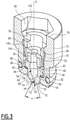
Fig 3 ] lafigure 3 est une vue en perspective présentant une coupe selon le deuxième plan de coupe II-II d'une portion du dispositif de lafigure 1 , - [
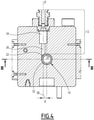
Fig 4 ] lafigure 4 est une vue du dessus présentant une coupe selon un troisième plan de coupe IV-IV du dispositif de lafigure 1 , et - [
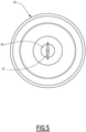
Fig 5 ] lafigure 5 est une vue de face de la buse du dispositif de lafigure 1 . - Un exemple de dispositif 10 de mélange pluri-composants selon un mode de réalisation de l'invention est représenté sur les
figure 1 à 5 . - Le dispositif de mélange 10 comprend au moins une première alimentation 12 d'un premier produit et une deuxième alimentation 14 d'un deuxième produit, une chambre de mélange 16 et une buse 18.
- Par buse, on entend un moyen apte à faire ou laisser passer un produit de n'importe quelle viscosité, également appelé injecteur ou insert, par exemple une buse fendue telle que décrite ci-après.
- La chambre de mélange 16 délimite un espace de mélange 20.
- La chambre de mélange 16 est, par exemple, réalisée en acier inoxydable.
- La chambre de mélange 16 présente au moins une première entrée 22 et une deuxième entrée 24, et en outre une sortie 26.
- La chambre de mélange 16 présente un axe d'écoulement D.
- L'axe d'écoulement D est ici sensiblement vertical. Cela permet notamment que l'écoulement soit facilité par la gravité.
- La chambre de mélange 16 s'étend ici entre une première extrémité et une deuxième extrémité selon l'axe d'écoulement D.
- La première extrémité correspond ici à une extrémité supérieure 28 de la chambre de mélange 16.
- La deuxième extrémité correspond ici à une extrémité inférieure 30 de la chambre de mélange 16.
- Dans l'exemple représenté, la chambre de mélange 16 présente sensiblement une forme d'un cylindre creux d'axe de cylindre l'axe d'écoulement D.
- La chambre de mélange 16 présente ici un rayon, par exemple de 7,5 mm.
- La chambre de mélange 16 comprend une paroi latérale 32 entre l'extrémité supérieure 28 et l'extrémité inférieure 30.
- La première entrée 22 est délimitée par la paroi latérale 32.
- La paroi latérale 32 est sensiblement cylindrique.
- La première entrée 22 présente la forme d'un disque projeté sur la paroi latérale 32.
- La deuxième entrée 24 est ici agencée à l'extrémité supérieure 28.
- La deuxième entrée 24 est centrée sur l'axe d'écoulement D.
- La deuxième entrée 24 présente la forme d'un disque.
- La sortie 26 correspond ici à l'extrémité inférieure 30 de la chambre de mélange 16.
- La sortie 26 est centrée sur l'axe d'écoulement D.
- La sortie 26 présente la forme d'un disque.
- La première alimentation 12 débouche dans la chambre de mélange 16 au niveau de la première entrée 22.
- La première alimentation 12 comprend une source de premier produit (non représentée) et un premier conduit d'alimentation 34.
- Le premier conduit d'alimentation 34 est, par exemple, réalisé en acier inoxydable.
- Le premier conduit d'alimentation 34 comprend une première portion aval 36, la première portion aval 36 débouchant dans la chambre de mélange 16, plus particulièrement au niveau de la première entrée 22.
- Dans l'exemple représenté, la première portion aval 36 présente une forme cylindrique.
- La première alimentation 12 est adaptée pour introduire le premier produit dans la chambre de mélange 16 selon un axe central d'alimentation D'.
- La première portion aval 36 s'étend ici principalement selon l'axe central d'alimentation D'.
- Plus particulièrement, la première portion aval 36 a pour axe de cylindre l'axe central d'alimentation D'.
- Les directions respectives de l'axe central d'alimentation D' et de l'axe d'écoulement D forment un angle compris entre 0° et 135°, plus particulièrement compris entre 0° et 90°.
- Dans le cas d'un angle de 0°, l'axe central d'alimentation et l'axe d'écoulement sont confondus. La première alimentation et la deuxième alimentation sont coaxiales. Plus particulièrement, la première entrée s'étend autour de la deuxième entrée. La première entrée présente, par exemple, une forme d'anneau, et la deuxième entrée présente une forme de disque entouré par le diamètre interne de l'anneau.
- L'angle sélectionné permet notamment d'obtenir plus ou moins de turbulences ou un écoulement plus proche d'un écoulement laminaire.
- Dans l'exemple représenté, l'axe central d'alimentation D' est orthogonal à l'axe d'écoulement D. L'axe central d'alimentation D' s'étend dans un plan perpendiculaire à l'axe d'écoulement D.
- L'axe central d'alimentation D' est, par exemple, horizontal.
- L'axe central d'alimentation D' et l'axe d'écoulement D définissent chacun une droite respective.
- Les droites définies par l'axe central d'alimentation D' et par l'axe d'écoulement D ne sont pas sécantes.
- Les droites présentent une distance d minimale l'une à l'autre, correspondant à la distance entre les droites.
- La distance d est non nulle.
- Ladite distance d non nulle est appelée par la suite décalage 38 entre l'axe central d'alimentation D' et l'axe d'écoulement D.
- Le décalage est substantiel, c'est-à-dire non négligeable, c'est-à-dire visible à l'œil nu.
- Le décalage est compris entre 3% de la valeur du rayon de chambre de mélange et la valeur du rayon de chambre de mélange, plus particulièrement entre 10% de la valeur du rayon de chambre de mélange et la valeur du rayon de chambre de mélange.
- Plus particulièrement ici, le décalage est compris entre 2,0 millimètres (mm) et 6,0 mm pour une chambre de mélange de rayon 6,0 mm.
- Ledit décalage permet notamment que le premier produit s'écoule avec un effet de tourbillon dans l'espace de mélange 20.
- Cela permet notamment de faciliter le mélange dans la chambre de mélange 14 en créant des turbulences.
- La distance selon la direction de l'axe d'écoulement D entre la première entrée 22 et la deuxième entrée 24 est inférieure ou égale à 15,0 mm, de préférence 13,0 mm, de préférence de 12,0 mm.
- La distance selon la direction de l'axe d'écoulement D s'étendant entre la première entrée 22 et la deuxième entrée 24 correspond, dans l'exemple représenté, à la distance entre la deuxième entrée 24 et une extrémité dite supérieure de la première entrée 22 selon la direction de l'axe d'écoulement D.
- La première alimentation 12 est ici adaptée pour générer un flux continu de premier produit à la première entrée 22.
- Le premier conduit d'alimentation 34 est, par exemple, dépourvu de vanne.
- Alternativement, le premier conduit d'alimentation 34 est pourvue d'une vanne configurée pour contrôler le flux de premier produit au niveau de la première entrée 22.
- La première alimentation 12 est dépourvue de buse adaptée pour injecter le premier produit depuis la première alimentation dans la chambre de mélange sous la forme d'un jet plat. Plus particulièrement ici, la première alimentation 12 est dépourvue de toute buse.
- La deuxième alimentation 14 débouche dans la chambre de mélange 16 au niveau de la deuxième entrée 24.
- La deuxième alimentation comprend une source de deuxième produit (non représenté) et un deuxième conduit d'alimentation 40.
- Le deuxième conduit d'alimentation 40, est, par exemple, réalisé en acier inoxydable.
- Le deuxième conduit d'alimentation 40 présente une surface intérieure 41 délimitant le passage du deuxième produit.
- Le deuxième conduit d'alimentation 40 comprend une deuxième portion aval 42, la deuxième portion aval 42 débouchant dans la chambre de mélange 16, plus particulièrement au niveau de la deuxième entrée 24.
- La deuxième alimentation 14 est adaptée pour que le deuxième produit présente une pression, plus particulièrement au niveau de la deuxième entrée 24, strictement supérieure à la pression du premier produit, plus particulièrement au niveau de la première entrée 22.
- La pression du premier produit est, par exemple, compris entre 1 bars, soit 1.105 Pa, et 500 bars, soit 5.107 Pa.
- La pression du deuxième produit est supérieure à la pression du premier produit d'au moins 1,0%, généralement d'au moins 5,0%.
- Cette valeur dépend notamment de la viscosité de chacun des produits à mélanger.
- Cela permet notamment d'améliorer l'homogénéisation du mélange.
- La buse 18 est agencée et adaptée pour injecter le deuxième produit depuis la deuxième alimentation 14 dans la chambre de mélange 16 sous la forme d'un jet plat.
- Le jet présente un angle de jet a, en sortie de buse, compris entre 50° et 80°.
- La buse 18 est agencée pour injecter le deuxième produit autour d'un axe central d'injection, l'axe central d'injection étant aligné, ou confondu, avec l'axe d'écoulement D.
- L'ensemble du deuxième produit passe à travers la buse 18 avant d'atteindre la chambre de mélange 16.
- La buse 18 est, par exemple, réalisée en carbure fondu, plus particulièrement de tungstène, en acier inoxydable 316 ou en céramique.
- La buse 18 est ici agencée dans la deuxième alimentation 14 à proximité de la deuxième entrée 24.
- La buse 18 est logée dans le deuxième conduit d'alimentation 40, plus particulièrement dans la deuxième portion aval 42.
- Dans l'exemple représenté, la buse 18 est maintenue dans le deuxième conduit d'alimentation 40 par un porte-buse 43 décrit par la suite.
- La buse 18 présente une forme extérieure présentant ici une symétrie de rotation autour de l'axe central de d'injection D.
- La buse 18 présente une extrémité aval 44, l'extrémité aval 44 correspondant au point de la buse 18 le plus en aval en considérant l'écoulement du deuxième produit.
- L'extrémité aval 44 est ici agencée à proximité de la deuxième entrée 24.
- L'extrémité aval 44 et la deuxième entrée 24 sont, par exemple, espacées d'une distance strictement inférieure à 5,0 mm, de préférence 3,0 mm, de préférence de 2,0 mm.
- L'extrémité aval 44 est, par exemple, en amont de la deuxième entrée 24 de ladite distance. L'injection du deuxième produit envoie le deuxième produit dans la chambre de mélange 16.
- Alternativement, l'extrémité aval 44 s'étend en aval de la deuxième entrée 24 dans la chambre de mélange 16. Ainsi, la buse 18 dépasse légèrement au niveau de l'extrémité aval 44 dans la chambre de mélange 16.
- La distance e selon la direction de l'axe d'écoulement D entre la première entrée 22 et l'extrémité aval 44 est inférieure ou égale à 10,0 mm.
- La distance selon la direction de l'axe d'écoulement D entre la première entrée 22 et l'extrémité aval 44 correspond, dans l'exemple représenté, à la distance entre l'extrémité aval 44 et l'extrémité supérieure de la première entrée 22 selon la direction de l'axe d'écoulement D.
- La buse 18 s'étend entre l'extrémité aval 44 et une extrémité amont 46 selon l'axe central d'injection D.
- La buse 18 présente une face amont 48, logée dans le deuxième conduit d'alimentation, et une face aval 50, opposée à la face amont 48 et faisant face à la chambre de mélange 16.
- La face amont 48 délimite l'extrémité amont 46.
- La face aval 50 délimite l'extrémité aval 44.
- La face amont 48 est sensiblement plane et est disposée sensiblement transversalement à l'axe central d'injection D.
- La face aval 50 est en forme de dôme centré sur l'axe central d'injection D et fendu d'au moins une, dans l'exemple représenté une unique, fente 52 perpendiculaire à l'axe central d'injection D.
- La fente 52 présente des lèvres 54 qui forment entre elles un angle compris typiquement entre 5° et 150°, de préférence compris entre 20° et 110°.
- La buse 18 présente ici une forme extérieure comprenant deux tronçons cylindriques, un premier tronçon cylindrique 56 délimitant la face amont 48 et un deuxième tronçon cylindrique 58 terminant par un dôme délimitant la face aval 50.
- Chaque tronçon cylindrique présente comme axe de cylindre l'axe central d'injection D.
- Le premier tronçon cylindrique 56 présente un diamètre strictement supérieur au diamètre du deuxième tronçon cylindrique 58.
- La buse 18 définit alors un épaulement 60 extérieur sur sa surface extérieure.
- L'épaulement 60 est ici circonférentiel.
- La buse 18 délimite au moins un passage 64.
- Dans l'exemple représenté, la buse 18 délimite un unique passage 64.
- Alternativement, la buse 18 délimite une pluralité de passages, par exemple entre deux et dix passages.
- La buse 18 délimite au moins un orifice d'éjection 62, dans l'exemple représenté un unique, le ou chaque orifice d'éjection 62 débouchant ici dans la face aval 50.
- La buse 18 comprend ici autant de passage(s) 64 que de fente(s) 52 et que d'orifice(s) d'éjection 62.
- Le ou chaque orifice d'éjection 62 forme ici une portion du passage 64 ou d'un passage respectif, plus particulièrement la portion du passage la plus en aval.
- Dans l'exemple représenté, le ou chaque passage 64 comprend, en outre, une cavité d'entrée 66 dans la buse, suivie d'un canal 68.
- Plus particulièrement, le ou chaque passage 64 est constitué, de l'amont vers l'aval, de la cavité d'entrée 66, du canal 68 et de l'orifice d'éjection 62.
- La cavité 64 débouche dans la face amont 48.
- La cavité 64 présente une section transversale décroissant vers l'aval.
- La cavité d'entrée 64 présente ici une symétrie par rotation autour de l'axe central d'injection D, le diamètre de la cavité d'entrée 64 décroissant depuis l'extrémité amont 46 ou la face amont 48 de la buse 18 jusqu'au canal 66.
- La cavité 64 a, dans l'exemple représenté, une forme de cloche.
- Le canal 66 présente une section transversale constante.
- Le canal 66 présente ici une forme cylindrique d'axe de cylindre l'axe central d'injection D.
- Le canal 66 s'étend dans la continuité de la cavité d'entrée 64.
- L'orifice d'éjection 62 comprend, plus particulièrement est formé par, de l'amont à l'aval, un rétrécissement 70 du passage et de la fente 52 ou d'une fente respective.
- Le rétrécissement 70 forme un rétrécissement du canal 68 à une extrémité aval du canal 68.
- Le rétrécissement 70 forme une section de passage circulaire.
- Le rétrécissement 70 présente, par exemple, une forme de dôme fendu par la fente 52.
- La fente 52 présente une dimension croissant de l'amont vers l'aval.
- L'intersection 72 de la fente 52 et du rétrécissement 70 forme une ellipse.
- L'ellipse présente un diamètre équivalent de 0,3 mm et 2,0mm, c'est-à-dire qu'elle présente une aire égale à l'air d'un cercle présentant le diamètre équivalent.
- Le porte-buse 43 est adapté pour porter la buse 18 et la maintenir solidaire de le deuxième conduit d'alimentation 40.
- Le porte-buse 43 est, par exemple, réalisé en acier inoxydable.
- Le porte-buse 43 présente ici une symétrie de rotation autour de l'axe central d'injection D.
- Le porte-buse 43 comprend ici une surface extérieure 74 apte à coopérer avec la surface intérieure 41 du deuxième conduit d'alimentation 40.
- La surface intérieure 41 du deuxième conduit d'alimentation 40 présente, par exemple, un taraudage, et la surface extérieure 74 présente un filetage complémentaire du taraudage.
- Alternativement, le porte-buse 43 est fretté dans le deuxième conduit d'alimentation 40, par exemple, à chaud, de sorte que la surface extérieure 74 s'étend contre la surface intérieure 41 du deuxième conduit d'alimentation 40.
- Le porte-buse 43 présente une face amont 76 et une face aval 78 selon l'axe central d'injection D.
- Le porte-buse 43 délimite, en outre, un logement 80 prévu pour recevoir la buse 18, plus particulièrement dans une portion aval du porte-buse 43.
- Le logement 80 est, par exemple, un orifice traversant selon l'axe central d'injection D.
- L'orifice traversant est délimité par une surface intérieure 81 du porte-buse 43.
- L'orifice traversant débouche d'une part dans la face amont 76 et d'autre part dans la face aval 78.
- La section transversale de l'orifice traversant décroit de l'amont vers l'aval.
- L'orifice traversant présente un épaulement 82.
- L'épaulement 82 est formé par un rétrécissement de l'orifice traversant allant de l'amont vers l'aval.
- L'épaulement 60 de la buse 18 coopère avec l'épaulement 82 du porte-buse 43.
- Un joint 84 est ici agencé entre l'épaulement 60 de la buse 18 et l'épaulement 82 du porte-buse 43.
- Le joint 84 est, par exemple, en polytétrafluoroéthylène (PTFE).
- Alternativement, le joint 84 est remplacé par de la colle.
- L'épaulement 82 du porte-buse 43 forme une butée de la buse 18 selon l'axe central d'injection D dans la direction amont vers aval.
- La buse 18 est, en outre, maintenue selon l'axe central d'injection D dans la direction aval vers amont par un deuxième système de butée.
- L'orifice traversant délimite ici dans une portion amont une empreinte 85 complémentaire d'un outil, par exemple une empreinte à section hexagonale.
- Cela permet notamment d'utiliser un outil pour fixer le porte-buse 43 dans le deuxième conduit d'alimentation 40, par exemple en vissant le porte-buse 43 à l'aide de l'outil dans le deuxième conduit d'alimentation 40.
- Un joint 86 est en outre ici agencé entre le porte-buse 43 et la surface intérieure 41 du deuxième conduit d'alimentation 40.
- Le joint 86 est, par exemple, en PTFE.
- La buse 18 est reçu dans le porte-buse 43, de sorte que l'extrémité aval 44, ici plus particulièrement l'ensemble de la face aval 50, de la buse 18 dépasse du porte-buse 43 au niveau de la face aval 78.
- La deuxième alimentation 14 comprend, en outre, une vanne d'injection 88.
- La vanne d'injection 88 est adaptée pour permettre sélectivement le passage du deuxième produit à travers elle.
- La vanne d'injection 88 est ici agencée dans la deuxième alimentation, plus particulièrement dans le deuxième conduit d'alimentation 40, en amont de la buse 18.
- La vanne d'injection 88 comprend ici un système comprenant un élément 90 déplaçable par rapport à un siège 92, conçus pour permettre le passage du deuxième liquide lorsque l'élément est écarté du siège et pour empêcher le passage du deuxième liquide lorsque l'élément s'étend contre le siège.
- Le siège 92 délimite un passage 95 présentant une section transversale décroissante de l'amont vers l'aval.
- Le passage présente, par exemple, une forme tronconique.
- La deuxième alimentation est telle que le deuxième produit de la deuxième alimentation passe nécessairement par le passage 95 délimité par le siège 92 avant d'atteindre la buse 18 et/ou la chambre de mélange 16.
- Le siège 92 est ici fixe par rapport à la buse 18.
- Plus particulièrement, le siège 92 est ici solidaire du porte-buse 43, par exemple via un élément de maintien 96.
- L'élément de maintien 96 présente une surface extérieure 98 prévue pour coopérer avec la surface intérieure 81 du porte-buse.
- La surface extérieure 98 présente, par exemple, un taraudage complémentaire d'un filetage de la surface intérieure 81 du porte-buse.
- L'élément de maintien 96 présente en outre un épaulement 100 apte à maintenir le siège selon l'axe central d'injection dans la direction allant de l'aval à l'amont.
- L'élément de maintien 96 présente, dans l'exemple représenté, une empreinte 102 complémentaire d'un outil.
- L'empreinte 102 correspond, par exemple, à une fente perpendiculaire à l'axe central d'injection. L'empreinte 102 est, par exemple, complémentaire d'un tournevis.
- Cela permet notamment d'utiliser un outil pour la mise en place de l'élément de maintien 96 dans le porte-buse.
- Le siège 92 s'appuie en aval sur la buse 18.
- Ainsi, le siège 92 forme le deuxième système de butée de la buse 18 selon l'axe central d'injection D, alors que la buse 18 forme un système de butée du siège 92 selon l'axe central d'injection pour la direction de l'amont vers l'aval.
- Un joint 104 est ici agencé entre le siège 92 et la buse 18.
- Le joint 104 est, par exemple, en PTFE.
- Ainsi, la buse 18, ici en outre le joint 104, et le siège 92 sont maintenus fixes par rapport au porte-buse 43 selon l'axe central d'injection D par l'épaulement 60 d'une part, et par l'élément de maintien solidaire du porte-buse 43 d'autre part.
- Alternativement, le siège 92 est fixé directement au porte-buse 43.
- L'élément déplaçable 90 est contrôlable pour ouvrir ou fermer sélectivement le passage 95 à travers le siège.
- Plus particulièrement ici, l'élément 90 comprend une balle 106 portée à une extrémité d'un pointeau 108.
- La balle 106 est dimensionnée de sorte qu'elle obture le passage 95 lorsqu'elle repose sur les bords dudit passage 95.
- Ainsi, la vanne d'injection 88 permet de contrôler le passage du deuxième produit à travers le deuxième conduit d'alimentation 40, vers la buse 18, et ainsi injecté dans la chambre de mélange 16.
- Le siège 92 et l'élément déplaçable 90 sont, par exemple, réalisés en acier inoxydable.
- Dans l'exemple représenté, le dispositif 10 comprend en outre une alimentation en air 110, la chambre de mélange 16 présentant en outre une entrée d'air 112.
- L'alimentation en air 110 débouche dans la chambre de mélange 16 au niveau de l'entrée d'air 112.
- L'entrée d'air 112 est agencée dans la paroi latérale 32 de la chambre de mélange 16.
- L'entrée d'air 112 est agencée en aval de la première entrée 22 du premier produit selon la direction d'écoulement D.
- L'air est injecté radialement dans la chambre de mélange 16.
- Cela permet notamment de créer des turbulences supplémentaires pour favoriser le mélange.
- Dans un exemple non représenté, le dispositif ne comprend pas de porte-buse, la buse étant fixée directement à la surface intérieure du deuxième conduit d'alimentation. Le siège, le cas échéant, est, par exemple, alors également fixée directement à la surface intérieure du deuxième conduit d'alimentation.
- Dans une alternative non représentée, le dispositif comprend plus de deux entrées de produit dans la chambre de mélange, de sorte à mélanger plus de deux produits dans la chambre de mélange. A au moins une des entrées, est agencée une buse comme décrit précédemment. Plus particulièrement, à toutes les entrées sauf une, est agencée une buse respective.
- Dans une autre alternative non représentée, le dispositif comprend une deuxième chambre de mélange comprenant similairement une première entrée de produit et une deuxième entrée de produit. La deuxième chambre de mélange est agencée en aval de la chambre de mélange décrite précédemment, la sortie de la chambre de mélange décrite formant l'alimentation reliée à la première entrée de la deuxième chambre de mélange, une alimentation d'un troisième produit étant reliée à la deuxième entrée de la deuxième chambre de mélange. Cela permet alors de mélanger trois produits successivement.
- Le dispositif est susceptible de comprendre ainsi autant de chambres de mélange agencées en série que souhaité, la sortie de chaque chambre de mélange en dehors de la dernière étant reliée à la première entrée de la chambre de mélange suivante.
- De manière générale, lorsqu'on mélange un nombre donné n de produits, le dispositif comprend ici n-1 buses, chaque entrée de produit étant pourvue d'une buse à l'exception d'une entrée d'un produit appelé la base du mélange.
- Un procédé de montage du dispositif 10 tel que décrit en regard des figures va maintenant être décrit.
- Ledit procédé est susceptible d'être adapté pour permettre le montage des variantes décrites du dispositif non représentées.
- Un dispositif comprenant une première alimentation 12, une deuxième alimentation 14 et une chambre de mélange 16 comme décrites précédemment est fourni.
- Une buse 18 telle que décrite est mise en place au niveau de la deuxième alimentation 14, de sorte à injecter le deuxième produit depuis la deuxième alimentation dans la chambre de mélange sous la forme d'un jet plat.
- Plus particulièrement, la buse 18 est placée dans le porte-buse 43, ici dans l'orifice traversant, plus particulièrement de sorte que l'épaulement 60 de la buse 18 repose sur l'épaulement 82 du porte-buse 43.
- Un joint 84, ici annulaire, par exemple, avantageusement placé entre les épaulements 60, 82.
- Un joint 104, ici annulaire, est ensuite, par exemple, placé sur la buse 18.
- Le siège 92 est ensuite placée conformément à ce qui a été décrit précédemment.
- Puis, l'élément de maintien 96 est inséré dans le porte-buse 43, de manière à rester solidaire dudit porte-buse 43. L'élément de maintien 96 est, par exemple, vissé dans le porte-buse 43, par exemple à l'aide d'un tournevis.
- L'ensemble formé ici de la buse 18, du siège 92, de l'élément de maintien 96 et, le cas échéant, des joints correspondant, est ici solidaire du porte-buse 43 dans l'orifice traversant.
- Un joint 86, ici annulaire, est agencé sur une surface extérieure du porte-buse 43 de manière à s'étendre entre le porte-buse 43 et la surface intérieure 41 du deuxième conduit d'alimentation 40.
- Le porte-buse 43 est alors inséré dans le deuxième conduit d'alimentation 40 et solidarisé audit deuxième conduit d'alimentation 40, par exemple par vissage, par exemple à l'aide d'une clé Allen, ou alternativement par frettage.
- Le porte-buse 43 est tel que la buse 18 injecte le deuxième produit dans la chambre de mélange.
- L'élément déplaçable 90 est, ensuite placé, ainsi qu'un actionneur de l'élément déplaçable, de sorte que ledit élément est déplaçable entre une position d'obturation dans lequel il s'étend contre le siège et une position de passage dans lequel il s'étend à l'écart du siège 92.
- Un procédé de mélange d'au moins un premier produit et un deuxième produit va maintenant être décrit.
- Un dispositif 10 tel que décrit précédemment est fourni.
- Un premier produit est fourni au niveau de la première entrée 22 dans la chambre de mélange 16 par la première alimentation 12.
- Un deuxième produit est fourni par la deuxième alimentation 14.
- Le deuxième produit présente une pression strictement supérieure à celle du premier produit, plus particulièrement d'au moins 1,0%, généralement d'au moins 5,0%, comme décrit précédemment.
- Le deuxième produit est injecté par la buse 18 dans la chambre de mélange 16 sous la forme d'un jet plat.
- Le jet présente un angle de jet α compris entre 50° et 80° en sortie de buse.
- Plus particulièrement, dans l'exemple représenté, l'élément 90 est écarté du siège 92 de manière à permettre le passage de deuxième produit à travers la vanne 88.
- Le deuxième produit pénètre dans la buse 18 et sors de la buse 18 au niveau de l'orifice d'éjection 62.
- Le deuxième produit est injecté sous la forme d'un jet plat sur le premier produit injecté dans la chambre de mélange.
- Cela favorise le mélange, le deuxième produit et le premier produit formant une surface de contact supérieure, par rapport à un cordon.
- Cela permet une meilleure répartition du deuxième produit dans le premier produit. Le premier produit et le deuxième produit sont ainsi mélangés de manière homogène en sortie de la chambre de mélange.
- Un tel dispositif de mélange permet, par exemple, de mélanger une base avec un catalyseur pour former un produit de revêtement, notamment dans le domaine de la peinture.
Claims (10)
- Dispositif de mélange (10) pluri-composants comprenant au moins une première alimentation (12) d'un premier produit et une deuxième alimentation (14) d'un deuxième produit, le dispositif de mélange (10) présentant une chambre de mélange (16) présentant au moins une première entrée (22) et une deuxième entrée (24), la première alimentation (12) débouchant dans la chambre de mélange (16) au niveau de la première entrée (22), la deuxième alimentation (14) débouchant dans la chambre de mélange (16) au niveau de la deuxième entrée (24), caractérisé en ce que le dispositif de mélange (10) comprend une buse (18) agencée et adaptée pour injecter le deuxième produit depuis la deuxième alimentation (14) dans la chambre de mélange (16) sous la forme d'un jet plat, présentant avantageusement un angle de jet (a) compris entre 50° et 80°.
- Dispositif de mélange selon la revendication 1, dans lequel la buse (18) est agencée dans la deuxième alimentation (14), la buse (18) comprenant une extrémité aval (44) agencée à proximité de la deuxième entrée (24), plus particulièrement à une distance strictement inférieure à 5,0 mm, de préférence 3,0 mm, de préférence de 2,0 mm.
- Dispositif de mélange selon la revendication 1 ou 2, dans lequel la buse (18) est agencée dans la deuxième alimentation (14), la buse (18) comprenant une extrémité aval (44), la distance selon la direction d'un axe d'écoulement (D) entre la première entrée (22) et l'extrémité aval (44) étant inférieure ou égale à 10,0 mm.
- Dispositif de mélange selon l'une quelconque des revendications 1 à 3, dans lequel la deuxième alimentation (14) est adaptée pour que le deuxième produit présente une pression strictement supérieure à la pression du premier produit, plus particulièrement d'au moins 1,0 %.
- Dispositif de mélange selon l'une quelconque des revendications 1 à 4, dans lequel la buse (18) délimite au moins un passage (64), le ou chaque passage comprenant un orifice d'éjection (62) comprenant d'amont en aval une section de passage circulaire (70) directement suivie d'une fente (52), la section de passage circulaire (70) et la fente (52) présentant une intersection (72), l'intersection (72) formant une ellipse.
- Dispositif de mélange selon l'une quelconque des revendications 1 à 5, dans lequel la chambre de mélange (16) présente un axe d'écoulement (D), la buse (18) étant agencée pour injecter le deuxième produit autour d'un axe central d'injection, l'axe central d'injection étant aligné avec l'axe d'écoulement (D).
- Dispositif de mélange selon l'une quelconque des revendications 1 à 6, dans lequel la chambre de mélange (16) présente un axe d'écoulement (D), la première alimentation (12) étant adaptée pour introduire le premier produit dans la chambre de mélange (16) selon un axe central d'alimentation (D'), l'axe central d'alimentation (D') et l'axe d'écoulement (D) définissant un angle compris entre 0° et 135°, plus particulièrement compris entre 0° et 90°.
- Dispositif de mélange selon l'une quelconque des revendications 1 à 7, dans lequel la chambre de mélange (16) présente un axe d'écoulement (D), la première alimentation (12) étant adaptée pour introduire le premier produit dans la chambre de mélange (16) selon un axe central d'alimentation (D'), l'axe central d'alimentation (D') et l'axe d'écoulement (D) définissant chacun une droite respective présentant une distance minimale l'une à l'autre non nulle dit décalage (38) entre l'axe central d'alimentation (D') et l'axe d'écoulement (D), le décalage (38) étant préférentiellement compris entre 3% de la valeur d'un rayon de la chambre de mélange et la valeur du rayon de la chambre de mélange.
- Dispositif de mélange selon l'une quelconque des revendications 1 à 8, comprenant une alimentation en air (110), la chambre de mélange (16) présentant une entrée d'air (112), l'alimentation en air (110) débouchant dans la chambre de mélange (16) au niveau de l'entrée d'air (112).
- Procédé de mélange d'au moins un premier produit et un deuxième produit, comprenant les étapes suivantes :- fourniture d'un dispositif de mélange (10) selon l'une quelconque des revendications 1 à 9,- alimentation en premier produit au niveau de la première entrée (22),- alimentation en deuxième produit au niveau de la deuxième entrée (24), et- injection du deuxième produit dans le premier produit dans la chambre de mélange (16) par la buse (18) sous la forme d'un jet plat, présentant avantageusement un angle de jet (a) compris entre 50° et 80°.
Applications Claiming Priority (1)
| Application Number | Priority Date | Filing Date | Title |
|---|---|---|---|
| FR2008721A FR3113608A1 (fr) | 2020-08-26 | 2020-08-26 | Dispositif de mélange pluri-composants et procédé associé |
Publications (3)
| Publication Number | Publication Date |
|---|---|
| EP3960283A1 true EP3960283A1 (fr) | 2022-03-02 |
| EP3960283C0 EP3960283C0 (fr) | 2025-08-13 |
| EP3960283B1 EP3960283B1 (fr) | 2025-08-13 |
Family
ID=73793341
Family Applications (1)
| Application Number | Title | Priority Date | Filing Date |
|---|---|---|---|
| EP21192961.7A Active EP3960283B1 (fr) | 2020-08-26 | 2021-08-25 | Dispositif de mélange pluri-composants et procédé associé |
Country Status (5)
| Country | Link |
|---|---|
| US (1) | US12214323B2 (fr) |
| EP (1) | EP3960283B1 (fr) |
| CN (1) | CN114100400B (fr) |
| ES (1) | ES3048510T3 (fr) |
| FR (1) | FR3113608A1 (fr) |
Families Citing this family (1)
| Publication number | Priority date | Publication date | Assignee | Title |
|---|---|---|---|---|
| FR3135628B1 (fr) | 2022-05-23 | 2025-10-10 | Air Liquide | Dispositif de fragmentation d’un liquide cryogénique dans une conduite de gaz. |
Citations (6)
| Publication number | Priority date | Publication date | Assignee | Title |
|---|---|---|---|---|
| GB2036586A (en) * | 1978-12-13 | 1980-07-02 | Upjohn Co | Liquids mixing device and method |
| EP0070487A1 (fr) * | 1981-07-22 | 1983-01-26 | MASCHINENFABRIK HENNECKE GmbH | Dispositif pour produire un mélange réactionnel de composants fluides au moins avec deux composantes de réaction capables de couler, réagissantes ensemble pour devenir une matière homogène ou de mousse |
| WO2001018451A1 (fr) * | 1999-09-06 | 2001-03-15 | Shell Internationale Research Maatschappij B.V. | Dispositif melangeur |
| US6590052B2 (en) * | 1997-10-28 | 2003-07-08 | Atofina | Process for continuous polymerization with micromixing of reactive fluids |
| US20030224308A1 (en) * | 2002-04-26 | 2003-12-04 | Fuji Photo Film Co., Ltd. | Method and apparatus for forming silver halide emulsion particles and method for forming fine particles |
| WO2011023302A1 (fr) * | 2009-08-26 | 2011-03-03 | Bayer Materialscience Ag | Procédé et dispositif de production d'une couche pulvérisée en matière plastique réactive |
Family Cites Families (23)
| Publication number | Priority date | Publication date | Assignee | Title |
|---|---|---|---|---|
| US2942655A (en) * | 1955-04-27 | 1960-06-28 | Fisher Scientific Co | Gas burner |
| US3121457A (en) * | 1956-12-11 | 1964-02-18 | Lummus Co | Burner assembly for synthesis gas generators |
| US2965303A (en) * | 1959-03-30 | 1960-12-20 | United Aircraft Corp | Coolant injection in a fuel nozzle |
| US3360201A (en) * | 1965-10-13 | 1967-12-26 | Gen Machine Company Inc | Oil burner combustion head |
| CA988557A (en) * | 1972-09-18 | 1976-05-04 | Ransburg Corporation | Apparatus for and method of spraying plural component materials |
| US4081958A (en) * | 1973-11-01 | 1978-04-04 | The Garrett Corporation | Low nitric oxide emission combustion system for gas turbines |
| US4012904A (en) * | 1975-07-17 | 1977-03-22 | Chrysler Corporation | Gas turbine burner |
| US4278418A (en) * | 1975-12-15 | 1981-07-14 | Strenkert Lynn A | Process and apparatus for stoichiometric combustion of fuel oil |
| US4116383A (en) * | 1977-02-10 | 1978-09-26 | United Technologies Corporation | Method and apparatus for mixing fluid |
| DE4414272A1 (de) * | 1994-04-23 | 1995-10-26 | Erz & Kohleflotation Gmbh | Vorrichtung zur Begasung einer Suspension |
| DE19757795A1 (de) * | 1997-12-29 | 1999-08-05 | Aventis Res & Tech Gmbh & Co | Vorrichtung zur Herstellung einer sich schnell verfestigenden Mischung aus mehreren Flüssigkeitskomponenten und anschließendem Versprühen der sich verfestigenden Mischung |
| WO2002072250A1 (fr) * | 2001-02-21 | 2002-09-19 | Metso Paper Inc | Ensemble pour melanger des courants dans un processus de fabrication du papier |
| FR2839269B1 (fr) * | 2002-05-06 | 2004-07-09 | Inst Francais Du Petrole | Dispositif perfectionne d'injection d'hydrocarbures dans une enceinte fluidisee |
| DE10249747A1 (de) * | 2002-10-25 | 2004-05-06 | Clariant Gmbh | Verfahren und Vorrichtung zur Durchführung chemischer und physikalischer Prozesse |
| US7866638B2 (en) * | 2005-02-14 | 2011-01-11 | Neumann Systems Group, Inc. | Gas liquid contactor and effluent cleaning system and method |
| CN201287027Y (zh) * | 2008-10-09 | 2009-08-12 | 郑州中原惠泉环保工程有限公司 | 一种脱硫塔用喷头 |
| JP5804543B2 (ja) * | 2010-04-05 | 2015-11-04 | 株式会社根本杏林堂 | ミキシングデバイス、ミキシングチューブ、薬液注入システム及び薬液の混合方法 |
| MX2013003307A (es) * | 2010-10-01 | 2013-06-05 | Sika Technology Ag | Aparato de mezcla para mezclas bombeables y metodo relaionado con el mismo. |
| BR112015004139A2 (pt) * | 2012-08-28 | 2017-07-04 | Basf Se | método e dispositivo de alimentação de pelo menos uma substância química a uma corrente de processo principal |
| KR102175882B1 (ko) * | 2013-11-01 | 2020-11-06 | 블라디미르 페도로프 | 기체와 액체 사이의 열 및 질량 교환을 위한 장치 및 방법 |
| CN105289346B (zh) * | 2015-11-27 | 2017-05-24 | 安徽理工大学 | 射流药剂分散系统及应用该系统的细煤粒调浆改质设备 |
| CN108939972B (zh) * | 2018-08-01 | 2023-05-05 | 华东石油成套设备扬中有限公司 | 内置式液体分散装置 |
| CN210097425U (zh) * | 2019-05-09 | 2020-02-21 | 南京林业大学 | 一种用于使空气和切削液混合均匀的混合器 |
-
2020
- 2020-08-26 FR FR2008721A patent/FR3113608A1/fr active Pending
-
2021
- 2021-08-25 ES ES21192961T patent/ES3048510T3/es active Active
- 2021-08-25 US US17/412,199 patent/US12214323B2/en active Active
- 2021-08-25 EP EP21192961.7A patent/EP3960283B1/fr active Active
- 2021-08-26 CN CN202110990769.2A patent/CN114100400B/zh active Active
Patent Citations (6)
| Publication number | Priority date | Publication date | Assignee | Title |
|---|---|---|---|---|
| GB2036586A (en) * | 1978-12-13 | 1980-07-02 | Upjohn Co | Liquids mixing device and method |
| EP0070487A1 (fr) * | 1981-07-22 | 1983-01-26 | MASCHINENFABRIK HENNECKE GmbH | Dispositif pour produire un mélange réactionnel de composants fluides au moins avec deux composantes de réaction capables de couler, réagissantes ensemble pour devenir une matière homogène ou de mousse |
| US6590052B2 (en) * | 1997-10-28 | 2003-07-08 | Atofina | Process for continuous polymerization with micromixing of reactive fluids |
| WO2001018451A1 (fr) * | 1999-09-06 | 2001-03-15 | Shell Internationale Research Maatschappij B.V. | Dispositif melangeur |
| US20030224308A1 (en) * | 2002-04-26 | 2003-12-04 | Fuji Photo Film Co., Ltd. | Method and apparatus for forming silver halide emulsion particles and method for forming fine particles |
| WO2011023302A1 (fr) * | 2009-08-26 | 2011-03-03 | Bayer Materialscience Ag | Procédé et dispositif de production d'une couche pulvérisée en matière plastique réactive |
Also Published As
| Publication number | Publication date |
|---|---|
| US20220062834A1 (en) | 2022-03-03 |
| FR3113608A1 (fr) | 2022-03-04 |
| CN114100400A (zh) | 2022-03-01 |
| EP3960283C0 (fr) | 2025-08-13 |
| ES3048510T3 (en) | 2025-12-10 |
| EP3960283B1 (fr) | 2025-08-13 |
| CN114100400B (zh) | 2026-08-04 |
| US12214323B2 (en) | 2025-02-04 |
Similar Documents
| Publication | Publication Date | Title |
|---|---|---|
| EP0802827B1 (fr) | Buse de pulverisation | |
| EP2139604A2 (fr) | Organe de pulverisation, dispositif de projection comportant un tel organe, installation de projection et methode de nettoyage d'un tel organe | |
| FR2663318A1 (fr) | Buse distributrice de boissons et procede de melange de liquides avec cette buse. | |
| EP3479906B1 (fr) | Buse de pulvérisation avec rétrécissement de pré-atomisation, et tête de pulvérisation et dispositif de pulvérisation comprenant une telle buse | |
| FR2628024A1 (fr) | Ensemble a buse de coupe par un jet de fluide | |
| FR2945461A1 (fr) | Projecteur et organe de pulverisation de produit de revetement et procede de projection mettant en oeuvre un tel projecteur. | |
| FR3050125A1 (fr) | Buse de pulverisation, notamment pour un systeme de distribution d'un produit sous pression muni d'un bouton poussoir, et systeme de distribution comprenant une telle buse | |
| FR2566680A1 (fr) | Buse de melange et de distribution | |
| EP3960283B1 (fr) | Dispositif de mélange pluri-composants et procédé associé | |
| FR3042127A1 (fr) | Bec d'injection pour composition cosmetique avec effet marbre, module et machine associes | |
| EP1192011B1 (fr) | Tete de pulverisation | |
| EP2143929B1 (fr) | Motor-fusée comprenant un dispositif d'injection de monoergol à débit modulable avec vitesse d'injection stable | |
| EP1677916B1 (fr) | Tete de pulverisation de produit fluide | |
| FR2521712A1 (fr) | Procede et appareil pour refroidir brusquement un objet | |
| EP0211295A1 (fr) | Procédé et dispositif d'injection, par voie pneumatique, de quantités dosées de matières pulvérulentes dans une enceinte se trouvant sous pression variable | |
| EP0683886A1 (fr) | Perfectionnement aux canons a neige. | |
| FR2526673A1 (fr) | Dispositif de melange de fluides de viscosites differentes | |
| WO2006123032A1 (fr) | Buse a chambre tourbillonnaire | |
| EP4134167B1 (fr) | Tête de lance | |
| FR2533838A1 (fr) | Buse de pulverisation | |
| EP1737315A2 (fr) | Dispositif de distribution de produits a obturateur rotatif | |
| EP3022038A1 (fr) | Dispositif d'extrusion de mélanges d'élastomères | |
| CH643878A5 (fr) | Procede et dispositif de production d'une mousse a partir d'un liquide visqueux. | |
| EP4729180A1 (fr) | Injecteur pour dispositif de pulvérisation et dispositif de pulvérisation associé | |
| FR2888762A1 (fr) | Buse a conduit divergent |
Legal Events
| Date | Code | Title | Description |
|---|---|---|---|
| PUAI | Public reference made under article 153(3) epc to a published international application that has entered the european phase |
Free format text: ORIGINAL CODE: 0009012 |
|
| STAA | Information on the status of an ep patent application or granted ep patent |
Free format text: STATUS: THE APPLICATION HAS BEEN PUBLISHED |
|
| AK | Designated contracting states |
Kind code of ref document: A1 Designated state(s): AL AT BE BG CH CY CZ DE DK EE ES FI FR GB GR HR HU IE IS IT LI LT LU LV MC MK MT NL NO PL PT RO RS SE SI SK SM TR |
|
| STAA | Information on the status of an ep patent application or granted ep patent |
Free format text: STATUS: REQUEST FOR EXAMINATION WAS MADE |
|
| 17P | Request for examination filed |
Effective date: 20220803 |
|
| RBV | Designated contracting states (corrected) |
Designated state(s): AL AT BE BG CH CY CZ DE DK EE ES FI FR GB GR HR HU IE IS IT LI LT LU LV MC MK MT NL NO PL PT RO RS SE SI SK SM TR |
|
| STAA | Information on the status of an ep patent application or granted ep patent |
Free format text: STATUS: EXAMINATION IS IN PROGRESS |
|
| 17Q | First examination report despatched |
Effective date: 20230404 |
|
| GRAP | Despatch of communication of intention to grant a patent |
Free format text: ORIGINAL CODE: EPIDOSNIGR1 |
|
| STAA | Information on the status of an ep patent application or granted ep patent |
Free format text: STATUS: GRANT OF PATENT IS INTENDED |
|
| INTG | Intention to grant announced |
Effective date: 20250507 |
|
| RIN1 | Information on inventor provided before grant (corrected) |
Inventor name: DEMESY, LUDOVIC Inventor name: JOUSSELIN, SEBASTIEN Inventor name: COGNON, THIBAULT |
|
| GRAS | Grant fee paid |
Free format text: ORIGINAL CODE: EPIDOSNIGR3 |
|
| GRAA | (expected) grant |
Free format text: ORIGINAL CODE: 0009210 |
|
| STAA | Information on the status of an ep patent application or granted ep patent |
Free format text: STATUS: THE PATENT HAS BEEN GRANTED |
|
| AK | Designated contracting states |
Kind code of ref document: B1 Designated state(s): AL AT BE BG CH CY CZ DE DK EE ES FI FR GB GR HR HU IE IS IT LI LT LU LV MC MK MT NL NO PL PT RO RS SE SI SK SM TR |
|
| REG | Reference to a national code |
Ref country code: GB Ref legal event code: FG4D Free format text: NOT ENGLISH |
|
| REG | Reference to a national code |
Ref country code: CH Ref legal event code: EP |
|
| REG | Reference to a national code |
Ref country code: DE Ref legal event code: R096 Ref document number: 602021035988 Country of ref document: DE |
|
| REG | Reference to a national code |
Ref country code: IE Ref legal event code: FG4D Free format text: LANGUAGE OF EP DOCUMENT: FRENCH |
|
| U01 | Request for unitary effect filed |
Effective date: 20250903 |
|
| U07 | Unitary effect registered |
Designated state(s): AT BE BG DE DK EE FI FR IT LT LU LV MT NL PT RO SE SI Effective date: 20250910 |
|
| PGFP | Annual fee paid to national office [announced via postgrant information from national office to epo] |
Ref country code: AT Payment date: 20251020 Year of fee payment: 5 |
|
| U20 | Renewal fee for the european patent with unitary effect paid |
Year of fee payment: 5 Effective date: 20251007 |
|
| REG | Reference to a national code |
Ref country code: ES Ref legal event code: FG2A Ref document number: 3048510 Country of ref document: ES Kind code of ref document: T3 Effective date: 20251210 |
|
| PG25 | Lapsed in a contracting state [announced via postgrant information from national office to epo] |
Ref country code: IS Free format text: LAPSE BECAUSE OF FAILURE TO SUBMIT A TRANSLATION OF THE DESCRIPTION OR TO PAY THE FEE WITHIN THE PRESCRIBED TIME-LIMIT Effective date: 20251213 |
|
| PGFP | Annual fee paid to national office [announced via postgrant information from national office to epo] |
Ref country code: GB Payment date: 20251007 Year of fee payment: 5 |
|
| PG25 | Lapsed in a contracting state [announced via postgrant information from national office to epo] |
Ref country code: NO Free format text: LAPSE BECAUSE OF FAILURE TO SUBMIT A TRANSLATION OF THE DESCRIPTION OR TO PAY THE FEE WITHIN THE PRESCRIBED TIME-LIMIT Effective date: 20251113 |
|
| PG25 | Lapsed in a contracting state [announced via postgrant information from national office to epo] |
Ref country code: HR Free format text: LAPSE BECAUSE OF FAILURE TO SUBMIT A TRANSLATION OF THE DESCRIPTION OR TO PAY THE FEE WITHIN THE PRESCRIBED TIME-LIMIT Effective date: 20250813 |
|
| PG25 | Lapsed in a contracting state [announced via postgrant information from national office to epo] |
Ref country code: GR Free format text: LAPSE BECAUSE OF FAILURE TO SUBMIT A TRANSLATION OF THE DESCRIPTION OR TO PAY THE FEE WITHIN THE PRESCRIBED TIME-LIMIT Effective date: 20251114 |
|
| PGFP | Annual fee paid to national office [announced via postgrant information from national office to epo] |
Ref country code: TR Payment date: 20251013 Year of fee payment: 5 |
|
| PG25 | Lapsed in a contracting state [announced via postgrant information from national office to epo] |
Ref country code: PL Free format text: LAPSE BECAUSE OF FAILURE TO SUBMIT A TRANSLATION OF THE DESCRIPTION OR TO PAY THE FEE WITHIN THE PRESCRIBED TIME-LIMIT Effective date: 20250813 |
|
| PG25 | Lapsed in a contracting state [announced via postgrant information from national office to epo] |
Ref country code: RS Free format text: LAPSE BECAUSE OF FAILURE TO SUBMIT A TRANSLATION OF THE DESCRIPTION OR TO PAY THE FEE WITHIN THE PRESCRIBED TIME-LIMIT Effective date: 20251113 |
|
| PGFP | Annual fee paid to national office [announced via postgrant information from national office to epo] |
Ref country code: ES Payment date: 20251008 Year of fee payment: 5 |
|
| REG | Reference to a national code |
Ref country code: CH Ref legal event code: H13 Free format text: ST27 STATUS EVENT CODE: U-0-0-H10-H13 (AS PROVIDED BY THE NATIONAL OFFICE) Effective date: 20260324 |
|
| PG25 | Lapsed in a contracting state [announced via postgrant information from national office to epo] |
Ref country code: SM Free format text: LAPSE BECAUSE OF FAILURE TO SUBMIT A TRANSLATION OF THE DESCRIPTION OR TO PAY THE FEE WITHIN THE PRESCRIBED TIME-LIMIT Effective date: 20250813 |
|
| PG25 | Lapsed in a contracting state [announced via postgrant information from national office to epo] |
Ref country code: CZ Free format text: LAPSE BECAUSE OF FAILURE TO SUBMIT A TRANSLATION OF THE DESCRIPTION OR TO PAY THE FEE WITHIN THE PRESCRIBED TIME-LIMIT Effective date: 20250813 Ref country code: CH Free format text: LAPSE BECAUSE OF NON-PAYMENT OF DUE FEES Effective date: 20250831 |
|
| PG25 | Lapsed in a contracting state [announced via postgrant information from national office to epo] |
Ref country code: SK Free format text: LAPSE BECAUSE OF FAILURE TO SUBMIT A TRANSLATION OF THE DESCRIPTION OR TO PAY THE FEE WITHIN THE PRESCRIBED TIME-LIMIT Effective date: 20250813 |
|
| PLBE | No opposition filed within time limit |
Free format text: ORIGINAL CODE: 0009261 |
|
| STAA | Information on the status of an ep patent application or granted ep patent |
Free format text: STATUS: NO OPPOSITION FILED WITHIN TIME LIMIT |
|
| REG | Reference to a national code |
Ref country code: CH Ref legal event code: L10 Free format text: ST27 STATUS EVENT CODE: U-0-0-L10-L00 (AS PROVIDED BY THE NATIONAL OFFICE) Effective date: 20260624 |
|
| PG25 | Lapsed in a contracting state [announced via postgrant information from national office to epo] |
Ref country code: MC Free format text: LAPSE BECAUSE OF FAILURE TO SUBMIT A TRANSLATION OF THE DESCRIPTION OR TO PAY THE FEE WITHIN THE PRESCRIBED TIME-LIMIT Effective date: 20250813 |
|
| PG25 | Lapsed in a contracting state [announced via postgrant information from national office to epo] |
Ref country code: IE Free format text: LAPSE BECAUSE OF NON-PAYMENT OF DUE FEES Effective date: 20250825 |
|
| 26N | No opposition filed |
Effective date: 20260515 |