EP3960090B1 - Drahtlose ultraschallvorrichtung mit zwei sonden, steuerungsverfahren dafür und steuerungssystem dafür - Google Patents
Drahtlose ultraschallvorrichtung mit zwei sonden, steuerungsverfahren dafür und steuerungssystem dafür Download PDFInfo
- Publication number
- EP3960090B1 EP3960090B1 EP19926005.0A EP19926005A EP3960090B1 EP 3960090 B1 EP3960090 B1 EP 3960090B1 EP 19926005 A EP19926005 A EP 19926005A EP 3960090 B1 EP3960090 B1 EP 3960090B1
- Authority
- EP
- European Patent Office
- Prior art keywords
- probe
- ultrasonic
- antenna
- dual
- sets
- Prior art date
- Legal status (The legal status is an assumption and is not a legal conclusion. Google has not performed a legal analysis and makes no representation as to the accuracy of the status listed.)
- Active
Links
Images

Classifications
-
- A—HUMAN NECESSITIES
- A61—MEDICAL OR VETERINARY SCIENCE; HYGIENE
- A61B—DIAGNOSIS; SURGERY; IDENTIFICATION
- A61B8/00—Diagnosis using ultrasonic, sonic or infrasonic waves
- A61B8/44—Constructional features of the ultrasonic, sonic or infrasonic diagnostic device
- A61B8/4477—Constructional features of the ultrasonic, sonic or infrasonic diagnostic device using several separate ultrasound transducers or probes
-
- A—HUMAN NECESSITIES
- A61—MEDICAL OR VETERINARY SCIENCE; HYGIENE
- A61B—DIAGNOSIS; SURGERY; IDENTIFICATION
- A61B8/00—Diagnosis using ultrasonic, sonic or infrasonic waves
- A61B8/44—Constructional features of the ultrasonic, sonic or infrasonic diagnostic device
- A61B8/4444—Constructional features of the ultrasonic, sonic or infrasonic diagnostic device related to the probe
- A61B8/4455—Features of the external shape of the probe, e.g. ergonomic aspects
-
- A—HUMAN NECESSITIES
- A61—MEDICAL OR VETERINARY SCIENCE; HYGIENE
- A61B—DIAGNOSIS; SURGERY; IDENTIFICATION
- A61B8/00—Diagnosis using ultrasonic, sonic or infrasonic waves
- A61B8/44—Constructional features of the ultrasonic, sonic or infrasonic diagnostic device
- A61B8/4444—Constructional features of the ultrasonic, sonic or infrasonic diagnostic device related to the probe
- A61B8/4472—Wireless probes
-
- A—HUMAN NECESSITIES
- A61—MEDICAL OR VETERINARY SCIENCE; HYGIENE
- A61B—DIAGNOSIS; SURGERY; IDENTIFICATION
- A61B8/00—Diagnosis using ultrasonic, sonic or infrasonic waves
- A61B8/54—Control of the diagnostic device
-
- A—HUMAN NECESSITIES
- A61—MEDICAL OR VETERINARY SCIENCE; HYGIENE
- A61B—DIAGNOSIS; SURGERY; IDENTIFICATION
- A61B8/00—Diagnosis using ultrasonic, sonic or infrasonic waves
- A61B8/56—Details of data transmission or power supply
Definitions
- the present application relates to the field of medical ultrasonic diagnostic imaging, and particularly to a dual-probe wireless ultrasonic device, a control method and a control system thereof.
- the dual-probe ultrasonic device includes: two sets of ultrasonic probes provided on a probe body and having different installation positions, a control board respectively connected to the two sets of ultrasonic probes and provided inside the probe body, and a communication device for transmitting images.
- USB cable is usually connected to the outside of the probe body to connect with an external communication device for image transmission.
- the communication device is an antenna which can transmit wireless signals to communicate with external devices and then transmit images.
- the dual-probe wireless ultrasonic device there are mainly two manners to install the antenna in the prior art.
- One is to install the antenna on an ultrasonic probe side.
- This installation manner is subject to requirements of synchronization signal transmission of the ultrasonic probe.
- the installation of the antenna on the ultrasonic probe side may affect the image quality.
- the other manner is to install the antenna on a main body housing. For this solution of installing the antenna on the main body housing, if the user holds the probe body during use, the antenna signal transmission is also affected.
- the document CN 101366662 A discloses a multi-headed imaging probe and an imaging system using the same.
- the diagnostic imaging system that includes an image acquisition component, a transmitter operatively coupled to the image acquisition component to transmit a signal therefrom, and a beamformer operatively coupled to the image acquisition component to receive image data therefrom.
- a processor configured to assemble images from the acquired image data and a display configured to display the images.
- the image acquisition component includes a multi-headed probe that has a plurality of transducers configured to permit a change of active transducers during an imaging session without a change of the image acquisition component.
- the document CN 101742968 A discloses a wireless ultrasound probe having a probe case enclosing a transducer array, a probe controller, and a transceiver which wirelessly receives control signals from and transmits image signals to a host system.
- a liquid-tight user interface including basic probe user controls such as directional controls, an image freeze control, and an image save control.
- the user interface may be fabricated as a touch panel LCD or OLED display.
- the probe may alternatively be controlled by a separate user interface which wirelessly transmits control signals to the host system or the probe. Either user interface may also include a display such as battery charge and signal strength indicators.
- the present application provides a dual-probe wireless ultrasonic device, a control method and a control system thereof.
- a dual-probe wireless ultrasonic device including: two sets of ultrasonic probes arranged on a probe body and having different installation positions, and a control board communicatively connected with the two sets of ultrasonic probes respectively and arranged inside the probe body;
- the dual-probe wireless ultrasonic device further includes: two sets of antennas for data transmission and communicatively connected with the control board;
- the two sets of ultrasonic probes comprise: a first ultrasonic probe and a second ultrasonic probe;
- the two sets of antennas comprising: a first antenna arranged on the second ultrasonic probe and communicatively connected with the first ultrasonic probe, and a second antenna arranged on the first ultrasonic probe and communicatively connected with the second ultrasonic probe.
- a material of the probe body is a metal material and/or a plastic material.
- the two sets of ultrasonic probes are respectively arranged at two opposite end portions of the probe body.
- At least one of the two sets of antennas is arranged away from the probe body.
- each ultrasonic probe includes: a housing configured to receive a functional component of the ultrasonic probe, and at least one of the two sets of antennas is arranged adjacent to an inner wall surface of the housing.
- At least one of the two sets of antennas is arranged on the inner wall surface of the housing.
- At least one of the two sets of antennas is glued and fixed on the inner wall surface of the housing, or fixed on the inner wall surface of the housing in a snap-fit manner.
- the dual-probe wireless ultrasonic device further includes: a battery arranged inside the probe body.
- a method for controlling a dual-probe wireless ultrasonic device of the above embodiment including:
- a system for controlling a dual-probe wireless ultrasonic device of the above embodiment including:
- the present application has the beneficial effects that: the dual-probe wireless ultrasonic device of the present application can wirelessly support the operation of dual-acoustic probes, and when any probe operates, the transmission of the probe signal is not interfered, thereby achieving an image with a better quality.
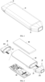
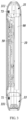
- the antennas include: a first antenna 71 provided on the second ultrasonic probe 33 and communicatively connected with the first ultrasonic probe 31, and a second antenna 73 provided on the first ultrasonic probe 31 and communicatively connected with the second ultrasonic probe 33.
- the two sets of antennas are arranged away from the probe body 10, to increase a distance between the corresponding ultrasonic probe and the antenna as far as possible to ensure the communication effect.
- the first ultrasonic probe 31 includes a housing 311 configured to receive a functional component of the first ultrasonic probe;
- the second ultrasonic probe 33 includes a housing 331 configured to receive a functional component of the second ultrasonic probe;
- the materials of the housings (311, 331) are all plastic materials.
- the two sets of antennas can be selectively arranged inside the corresponding ultrasonic probes respectively.
- the functional component is, for example, a transducer, etc., which is not described in detail here.
- the two sets of antennas (71, 73) can be selectively arranged adjacent to inner wall surfaces of the corresponding housings (331, 311) respectively.
- the two sets of antennas (71, 73) can be selectively arranged on the inner wall surfaces of the corresponding housings (331, 311) respectively.
- the two sets of antennas (71, 73) can be fixed on the inner wall surfaces of the corresponding housings (331, 311) respectively in a variety of ways, for example, can be glued and fixed on the inner wall surfaces of the housings respectively, or fixed on the inner wall surfaces of the housings respectively in a snap-fit manner, which will not be described in detail here.
- the first antenna 71 is glued and fixed on the inner wall surface of the housing 331 of the second ultrasonic probe 33, and is arranged adjacent to the housing 331 and away from the end portion of the probe body 10.
- the second antenna is glued and fixed on the inner wall surface of the housing 311 of the first ultrasonic probe 31, and is arranged adjacent to the housing 311 and away from the end portion of the probe body 10.
- the first antenna 71 and the second antenna 73 are both communicatively connected with the control board 50 through a cable, and the control board 50 controls the conductions of the two sets of antennas during the operation of the dual-probe wireless ultrasonic device.
- the specific conduction process will be described in detail below.
- the dual-probe wireless ultrasonic device further includes: a battery 90 arranged inside the probe body.
- the battery 90 is configured to provide power to the entire device to satisfy various application scenarios, which will not be detailed here.
- a method for controlling a dual-probe wireless ultrasonic device as described above includes: if the first ultrasonic probe is monitored and activated, the first antenna is turned on while the second antenna is turned off; if the second ultrasonic probe is monitored and activated, the second antenna is turned on while the first antenna is turned off; the first antenna is arranged on the second ultrasonic probe, and the second antenna is arranged on the first ultrasonic probe.
- the second antenna arranged thereon is automatically turned off, and the first antenna which is away from the first ultrasonic probe and is arranged on the second ultrasonic probe is activated; when the second ultrasonic probe operates, the first antenna arranged thereon is automatically turned off, and the second antenna which is away from the second ultrasonic probe and is arranged on the first ultrasonic probe is activated; thus, it can be ensured that each ultrasonic probe is not interfered by a signal from the antenna arranged thereon when operating; at the same time, because the antenna is arranged on the ultrasonic probe, the user can also hold any position on the probe body when using the wireless ultrasonic device, which is convenient for the user to operate.
- the present application also provides a system for controlling a dual-probe wireless ultrasonic device as described above, the system includes: an operation state monitoring module 100 and a control conversion module 200.
- the working status monitoring module 100 is configured to monitor a currently activated ultrasonic probe in real time after the dual-probe wireless ultrasonic device is turned on.
- the control conversion module 200 is configured to control turn-on of the antenna through the activated ultrasonic probe; if the first ultrasonic probe is monitored and activated, the first antenna is turned on while the second antenna is turned off; if the second ultrasonic probe is monitored and activated, the second antenna is turned on while the first antenna is turned off.
- the first antenna is arranged on the second ultrasonic probe, and the second antenna is arranged on the first ultrasonic probe.
- the dual-probe wireless ultrasonic device in the present application can wirelessly support dual-acoustic probe operation; and when any probe operates, the transmission of the probe signal is not interfered, thereby obtaining images with a higher quality.
Landscapes
- Health & Medical Sciences (AREA)
- Life Sciences & Earth Sciences (AREA)
- Engineering & Computer Science (AREA)
- Heart & Thoracic Surgery (AREA)
- Molecular Biology (AREA)
- Biophysics (AREA)
- Nuclear Medicine, Radiotherapy & Molecular Imaging (AREA)
- Pathology (AREA)
- Radiology & Medical Imaging (AREA)
- Biomedical Technology (AREA)
- Veterinary Medicine (AREA)
- Medical Informatics (AREA)
- Physics & Mathematics (AREA)
- Surgery (AREA)
- Animal Behavior & Ethology (AREA)
- General Health & Medical Sciences (AREA)
- Public Health (AREA)
- Computer Networks & Wireless Communication (AREA)
- Gynecology & Obstetrics (AREA)
- Ultra Sonic Daignosis Equipment (AREA)
Claims (10)
- Drahtlose Doppelsonden-Ultraschallvorrichtung mit: zwei Sätzen von Ultraschallsonden, die an einem Sondenkörper (10) angeordnet sind und unterschiedliche Installationspositionen haben, und einer Steuerplatine (50), die kommunikativ mit den beiden Sätzen von Ultraschallsonden verbunden ist und im Inneren des Sondenkörpers (10) angeordnet ist,wobei die drahtlose Doppelsonden-Ultraschallvorrichtung ferner Folgendes aufweist: zwei Sätze von Antennen für die Datenübertragung, die kommunikativ mit der Steuerplatine verbunden sind;wobei die zwei Sätze von Ultraschallsonden Folgendes aufweisen: eine erste Ultraschallsonde (31) und eine zweite Ultraschallsonde (33);die zwei Sätze von Antennen Folgendes aufweisen: eine erste Antenne (71), die an der zweiten Ultraschallsonde (33) angeordnet und mit der ersten Ultraschallsonde (31) kommunikativ verbunden ist, und eine zweite Antenne (73), die an der ersten Ultraschallsonde (31) angeordnet und mit der zweiten Ultraschallsonde (33) kommunikativ verbunden ist.
- Drahtlose Doppelsonden-Ultraschallvorrichtung nach Anspruch 1, wobei ein Material des Sondenkörpers (10) ein Metallmaterial und/oder ein Kunststoffmaterial ist.
- Drahtlose Doppelsonden-Ultraschallvorrichtung nach Anspruch 1, wobei die zwei Sätze von Ultraschallsonden jeweils an zwei gegenüberliegenden Endabschnitten des Sondenkörpers (10) angeordnet sind.
- Drahtlose Doppelsonden-Ultraschallvorrichtung nach Anspruch 1, wobei mindestens einer der zwei Sätze von Antennen entfernt vom Sondenkörper (10) angeordnet ist.
- Drahtlose Doppelsonden-Ultraschallvorrichtung nach Anspruch 1, wobei jede Ultraschallsonde Folgendes aufweist: ein Gehäuse (311, 331), das so konfiguriert ist, dass es eine Funktionskomponente der Ultraschallsonde aufnimmt, und mindestens einer der zwei Sätze von Antennen angrenzend an eine Innenwandfläche des Gehäuses (311, 331) angeordnet ist.
- Drahtlose Doppelsonden-Ultraschallvorrichtung nach Anspruch 5, wobei mindestens einer der zwei Sätze von Antennen an der Innenwandfläche des Gehäuses (311, 331) angeordnet ist.
- Drahtlose Doppelsonden-Ultraschallvorrichtung nach Anspruch 6, wobei mindestens einer der zwei Sätze von Antennen auf die Innenwandfläche des Gehäuses (311, 331) geklebt und befestigt ist oder auf der Innenwandfläche des Gehäuses (311, 331) durch Einrasten befestigt ist.
- Drahtlose Doppelsonden-Ultraschallvorrichtung nach Anspruch 6, wobei die drahtlose Doppelsonden-Ultraschallvorrichtung ferner eine Batterie (90) aufweist, die im Inneren des Sondenkörpers (10) angeordnet ist.
- Verfahren zur Steuerung einer drahtlosen Doppelsonden-Ultraschallvorrichtung nach Anspruch 1, wobei das Verfahren die folgenden Schritte aufweist:Überwachen einer aktuell aktivierten Ultraschallsonde der ersten Ultraschallsonde und der zweiten Ultraschallsonde in Echtzeit nach einem Einschalten der drahtlosen Doppelsonden-Ultraschallvorrichtung,wenn die erste Ultraschallsonde überwacht und aktiviert ist, Einschalten der ersten Antenne und Ausschalten der zweiten Antenne;wenn die zweite Ultraschallsonde überwacht und aktiviert wird, Einschalten der zweiten Antenne und das Ausschalten der ersten Antenne.
- System zur Steuerung einer drahtlosen Doppelsonden-Ultraschallvorrichtung nach Anspruch 1, wobei das System Folgendes aufweist:ein Betriebszustandsüberwachungsmodul (100), das so konfiguriert ist, dass es eine aktuell aktivierte Ultraschallsonde der ersten Ultraschallsonde und der zweiten Ultraschallsonde in Echtzeit überwacht, nachdem die drahtlose Doppelsonden-Ultraschallvorrichtung eingeschaltet wurde;ein Steuerumwandlungsmodul (200), das so konfiguriert ist, dass es Einschalten einer Antenne der ersten Ultraschallsonde und der zweiten Antenne durch die aktivierte Ultraschallsonde steuert;wobei, wenn die erste Ultraschallsonde überwacht und aktiviert wird, die erste Antenne eingeschaltet wird und die zweite Antenne ausgeschaltet wird,wenn die zweite Ultraschallsonde überwacht und aktiviert wird, die zweite Antenne eingeschaltet wird und die erste Antenne ausgeschaltet wird.
Applications Claiming Priority (2)
| Application Number | Priority Date | Filing Date | Title |
|---|---|---|---|
| CN201910335638.3A CN109893170B (zh) | 2019-04-24 | 2019-04-24 | 双探头无线超声装置、其控制方法及控制系统 |
| PCT/CN2019/123868 WO2020215740A1 (zh) | 2019-04-24 | 2019-12-09 | 双探头无线超声装置、其控制方法及控制系统 |
Publications (3)
| Publication Number | Publication Date |
|---|---|
| EP3960090A1 EP3960090A1 (de) | 2022-03-02 |
| EP3960090A4 EP3960090A4 (de) | 2023-01-11 |
| EP3960090B1 true EP3960090B1 (de) | 2025-01-08 |
Family
ID=66956406
Family Applications (1)
| Application Number | Title | Priority Date | Filing Date |
|---|---|---|---|
| EP19926005.0A Active EP3960090B1 (de) | 2019-04-24 | 2019-12-09 | Drahtlose ultraschallvorrichtung mit zwei sonden, steuerungsverfahren dafür und steuerungssystem dafür |
Country Status (3)
| Country | Link |
|---|---|
| EP (1) | EP3960090B1 (de) |
| CN (1) | CN109893170B (de) |
| WO (1) | WO2020215740A1 (de) |
Families Citing this family (4)
| Publication number | Priority date | Publication date | Assignee | Title |
|---|---|---|---|---|
| CN109893170B (zh) * | 2019-04-24 | 2021-02-09 | 飞依诺科技(苏州)有限公司 | 双探头无线超声装置、其控制方法及控制系统 |
| CN111616742B (zh) * | 2020-06-30 | 2025-01-03 | 广州索诺星信息科技有限公司 | 一种双头多功能的探头式b超仪 |
| CN112603365B (zh) * | 2020-12-18 | 2025-01-07 | 无锡祥生医疗科技股份有限公司 | 可切换的超声探头和超声设备 |
| EP4434469B1 (de) | 2023-03-22 | 2025-11-12 | Samsung Medison Co., Ltd. | Drahtlose sonde |
Family Cites Families (7)
| Publication number | Priority date | Publication date | Assignee | Title |
|---|---|---|---|---|
| US20100160786A1 (en) * | 2007-06-01 | 2010-06-24 | Koninklijke Philips Electronics N.V. | Wireless Ultrasound Probe User Interface |
| US8043221B2 (en) * | 2007-08-17 | 2011-10-25 | General Electric Company | Multi-headed imaging probe and imaging system using same |
| CN201629739U (zh) * | 2010-02-04 | 2010-11-10 | 华为终端有限公司 | 切换装置和无线终端 |
| TW201328206A (zh) * | 2011-12-30 | 2013-07-01 | Fih Hong Kong Ltd | 無線通訊裝置 |
| CN106999149B (zh) * | 2014-11-25 | 2020-09-29 | 皇家飞利浦有限公司 | 多传感器超声探头及相关方法 |
| CN105147323A (zh) * | 2015-10-14 | 2015-12-16 | 苏州斯科特医学影像科技有限公司 | 医用无线wifi传输b超设备 |
| CN109893170B (zh) * | 2019-04-24 | 2021-02-09 | 飞依诺科技(苏州)有限公司 | 双探头无线超声装置、其控制方法及控制系统 |
-
2019
- 2019-04-24 CN CN201910335638.3A patent/CN109893170B/zh active Active
- 2019-12-09 EP EP19926005.0A patent/EP3960090B1/de active Active
- 2019-12-09 WO PCT/CN2019/123868 patent/WO2020215740A1/zh not_active Ceased
Also Published As
| Publication number | Publication date |
|---|---|
| EP3960090A1 (de) | 2022-03-02 |
| EP3960090A4 (de) | 2023-01-11 |
| CN109893170A (zh) | 2019-06-18 |
| CN109893170B (zh) | 2021-02-09 |
| WO2020215740A1 (zh) | 2020-10-29 |
Similar Documents
| Publication | Publication Date | Title |
|---|---|---|
| EP3960090A1 (de) | Drahtlose ultraschallvorrichtung mit zwei sonden, steuerungsverfahren dafür und steuerungssystem dafür | |
| US12508005B2 (en) | Multi-purpose ultrasound image acquisition device | |
| EP3666194B1 (de) | Drahtlose ultraschallsondenkopplung mit einem mobilen ultraschallsystem | |
| CN102551798B (zh) | 无线超声诊断系统 | |
| JP5761829B2 (ja) | 水中通信システム | |
| US6364839B1 (en) | Ultrasound diagnostic instrument having software in detachable scanhead | |
| EP3415095B1 (de) | Doppler-fötusherzmessgerät | |
| US20090043204A1 (en) | Hand-held ultrasound imaging device having removable transducer arrays | |
| EP2510880A1 (de) | Ultraschalldiagnosesystem | |
| US20030181811A1 (en) | Diagnostic information generation apparatus and ultrasonic diagnostic system | |
| CN106073819A (zh) | 医疗诊断成像超声探针电池组无线电设备 | |
| US20160320474A1 (en) | Transducer having surface mounted elements and associated methods | |
| KR20100057341A (ko) | 무선 통신이 가능한 초음파 시스템 | |
| CN102415904A (zh) | 超声波探头 | |
| CN111220969B (zh) | 水下通讯声纳的陆上组网训练和性能测试一体化装置 | |
| JP2009038606A (ja) | 画像形成装置 | |
| JP7680894B2 (ja) | 超音波プローブおよび無線超音波プローブ | |
| CN218512633U (zh) | 便携式机械扫描探鱼声呐设备 | |
| JP4806582B2 (ja) | ワイヤレス超音波診断装置 | |
| CN221926619U (zh) | 一种分布式可重构穿墙雷达探测系统 | |
| CN213750325U (zh) | 雷达设备、可移动平台及无人机 | |
| EP3664717B1 (de) | Verbinder für ultraschallbildgebungssystem | |
| KR20110130958A (ko) | 디스플레이 장치용 송수신장치 | |
| CA2372152C (en) | Ultrasound diagnostic instrument having software in detachable scanhead | |
| CN204016336U (zh) | B超扫描探头和b超扫描系统 |
Legal Events
| Date | Code | Title | Description |
|---|---|---|---|
| STAA | Information on the status of an ep patent application or granted ep patent |
Free format text: STATUS: THE INTERNATIONAL PUBLICATION HAS BEEN MADE |
|
| PUAI | Public reference made under article 153(3) epc to a published international application that has entered the european phase |
Free format text: ORIGINAL CODE: 0009012 |
|
| STAA | Information on the status of an ep patent application or granted ep patent |
Free format text: STATUS: REQUEST FOR EXAMINATION WAS MADE |
|
| 17P | Request for examination filed |
Effective date: 20210923 |
|
| AK | Designated contracting states |
Kind code of ref document: A1 Designated state(s): AL AT BE BG CH CY CZ DE DK EE ES FI FR GB GR HR HU IE IS IT LI LT LU LV MC MK MT NL NO PL PT RO RS SE SI SK SM TR |
|
| DAV | Request for validation of the european patent (deleted) | ||
| DAX | Request for extension of the european patent (deleted) | ||
| A4 | Supplementary search report drawn up and despatched |
Effective date: 20221209 |
|
| RIC1 | Information provided on ipc code assigned before grant |
Ipc: A61B 8/00 20060101AFI20221205BHEP |
|
| P01 | Opt-out of the competence of the unified patent court (upc) registered |
Effective date: 20230530 |
|
| GRAP | Despatch of communication of intention to grant a patent |
Free format text: ORIGINAL CODE: EPIDOSNIGR1 |
|
| STAA | Information on the status of an ep patent application or granted ep patent |
Free format text: STATUS: GRANT OF PATENT IS INTENDED |
|
| INTG | Intention to grant announced |
Effective date: 20240801 |
|
| RIN1 | Information on inventor provided before grant (corrected) |
Inventor name: GUO, MINGKUN |
|
| GRAS | Grant fee paid |
Free format text: ORIGINAL CODE: EPIDOSNIGR3 |
|
| GRAA | (expected) grant |
Free format text: ORIGINAL CODE: 0009210 |
|
| STAA | Information on the status of an ep patent application or granted ep patent |
Free format text: STATUS: THE PATENT HAS BEEN GRANTED |
|
| AK | Designated contracting states |
Kind code of ref document: B1 Designated state(s): AL AT BE BG CH CY CZ DE DK EE ES FI FR GB GR HR HU IE IS IT LI LT LU LV MC MK MT NL NO PL PT RO RS SE SI SK SM TR |
|
| REG | Reference to a national code |
Ref country code: GB Ref legal event code: FG4D |
|
| REG | Reference to a national code |
Ref country code: CH Ref legal event code: EP |
|
| REG | Reference to a national code |
Ref country code: DE Ref legal event code: R096 Ref document number: 602019064765 Country of ref document: DE |
|
| REG | Reference to a national code |
Ref country code: IE Ref legal event code: FG4D |
|
| REG | Reference to a national code |
Ref country code: LT Ref legal event code: MG9D |
|
| REG | Reference to a national code |
Ref country code: NL Ref legal event code: MP Effective date: 20250108 |
|
| REG | Reference to a national code |
Ref country code: AT Ref legal event code: MK05 Ref document number: 1757802 Country of ref document: AT Kind code of ref document: T Effective date: 20250108 |
|
| PG25 | Lapsed in a contracting state [announced via postgrant information from national office to epo] |
Ref country code: NL Free format text: LAPSE BECAUSE OF FAILURE TO SUBMIT A TRANSLATION OF THE DESCRIPTION OR TO PAY THE FEE WITHIN THE PRESCRIBED TIME-LIMIT Effective date: 20250108 |
|
| PG25 | Lapsed in a contracting state [announced via postgrant information from national office to epo] |
Ref country code: RS Free format text: LAPSE BECAUSE OF FAILURE TO SUBMIT A TRANSLATION OF THE DESCRIPTION OR TO PAY THE FEE WITHIN THE PRESCRIBED TIME-LIMIT Effective date: 20250408 |
|
| PG25 | Lapsed in a contracting state [announced via postgrant information from national office to epo] |
Ref country code: FI Free format text: LAPSE BECAUSE OF FAILURE TO SUBMIT A TRANSLATION OF THE DESCRIPTION OR TO PAY THE FEE WITHIN THE PRESCRIBED TIME-LIMIT Effective date: 20250108 |
|
| PG25 | Lapsed in a contracting state [announced via postgrant information from national office to epo] |
Ref country code: PL Free format text: LAPSE BECAUSE OF FAILURE TO SUBMIT A TRANSLATION OF THE DESCRIPTION OR TO PAY THE FEE WITHIN THE PRESCRIBED TIME-LIMIT Effective date: 20250108 |
|
| PG25 | Lapsed in a contracting state [announced via postgrant information from national office to epo] |
Ref country code: ES Free format text: LAPSE BECAUSE OF FAILURE TO SUBMIT A TRANSLATION OF THE DESCRIPTION OR TO PAY THE FEE WITHIN THE PRESCRIBED TIME-LIMIT Effective date: 20250108 |
|
| PG25 | Lapsed in a contracting state [announced via postgrant information from national office to epo] |
Ref country code: IS Free format text: LAPSE BECAUSE OF FAILURE TO SUBMIT A TRANSLATION OF THE DESCRIPTION OR TO PAY THE FEE WITHIN THE PRESCRIBED TIME-LIMIT Effective date: 20250508 Ref country code: NO Free format text: LAPSE BECAUSE OF FAILURE TO SUBMIT A TRANSLATION OF THE DESCRIPTION OR TO PAY THE FEE WITHIN THE PRESCRIBED TIME-LIMIT Effective date: 20250408 |
|
| PG25 | Lapsed in a contracting state [announced via postgrant information from national office to epo] |
Ref country code: HR Free format text: LAPSE BECAUSE OF FAILURE TO SUBMIT A TRANSLATION OF THE DESCRIPTION OR TO PAY THE FEE WITHIN THE PRESCRIBED TIME-LIMIT Effective date: 20250108 |
|
| PG25 | Lapsed in a contracting state [announced via postgrant information from national office to epo] |
Ref country code: PT Free format text: LAPSE BECAUSE OF FAILURE TO SUBMIT A TRANSLATION OF THE DESCRIPTION OR TO PAY THE FEE WITHIN THE PRESCRIBED TIME-LIMIT Effective date: 20250508 Ref country code: LV Free format text: LAPSE BECAUSE OF FAILURE TO SUBMIT A TRANSLATION OF THE DESCRIPTION OR TO PAY THE FEE WITHIN THE PRESCRIBED TIME-LIMIT Effective date: 20250108 |
|
| PG25 | Lapsed in a contracting state [announced via postgrant information from national office to epo] |
Ref country code: GR Free format text: LAPSE BECAUSE OF FAILURE TO SUBMIT A TRANSLATION OF THE DESCRIPTION OR TO PAY THE FEE WITHIN THE PRESCRIBED TIME-LIMIT Effective date: 20250409 Ref country code: BG Free format text: LAPSE BECAUSE OF FAILURE TO SUBMIT A TRANSLATION OF THE DESCRIPTION OR TO PAY THE FEE WITHIN THE PRESCRIBED TIME-LIMIT Effective date: 20250108 |
|
| PG25 | Lapsed in a contracting state [announced via postgrant information from national office to epo] |
Ref country code: AT Free format text: LAPSE BECAUSE OF FAILURE TO SUBMIT A TRANSLATION OF THE DESCRIPTION OR TO PAY THE FEE WITHIN THE PRESCRIBED TIME-LIMIT Effective date: 20250108 |
|
| PG25 | Lapsed in a contracting state [announced via postgrant information from national office to epo] |
Ref country code: SE Free format text: LAPSE BECAUSE OF FAILURE TO SUBMIT A TRANSLATION OF THE DESCRIPTION OR TO PAY THE FEE WITHIN THE PRESCRIBED TIME-LIMIT Effective date: 20250108 |
|
| PG25 | Lapsed in a contracting state [announced via postgrant information from national office to epo] |
Ref country code: SM Free format text: LAPSE BECAUSE OF FAILURE TO SUBMIT A TRANSLATION OF THE DESCRIPTION OR TO PAY THE FEE WITHIN THE PRESCRIBED TIME-LIMIT Effective date: 20250108 |
|
| REG | Reference to a national code |
Ref country code: DE Ref legal event code: R097 Ref document number: 602019064765 Country of ref document: DE |
|
| PG25 | Lapsed in a contracting state [announced via postgrant information from national office to epo] |
Ref country code: DK Free format text: LAPSE BECAUSE OF FAILURE TO SUBMIT A TRANSLATION OF THE DESCRIPTION OR TO PAY THE FEE WITHIN THE PRESCRIBED TIME-LIMIT Effective date: 20250108 |
|
| PG25 | Lapsed in a contracting state [announced via postgrant information from national office to epo] |
Ref country code: EE Free format text: LAPSE BECAUSE OF FAILURE TO SUBMIT A TRANSLATION OF THE DESCRIPTION OR TO PAY THE FEE WITHIN THE PRESCRIBED TIME-LIMIT Effective date: 20250108 Ref country code: CZ Free format text: LAPSE BECAUSE OF FAILURE TO SUBMIT A TRANSLATION OF THE DESCRIPTION OR TO PAY THE FEE WITHIN THE PRESCRIBED TIME-LIMIT Effective date: 20250108 |
|
| PG25 | Lapsed in a contracting state [announced via postgrant information from national office to epo] |
Ref country code: RO Free format text: LAPSE BECAUSE OF FAILURE TO SUBMIT A TRANSLATION OF THE DESCRIPTION OR TO PAY THE FEE WITHIN THE PRESCRIBED TIME-LIMIT Effective date: 20250108 |
|
| PG25 | Lapsed in a contracting state [announced via postgrant information from national office to epo] |
Ref country code: SK Free format text: LAPSE BECAUSE OF FAILURE TO SUBMIT A TRANSLATION OF THE DESCRIPTION OR TO PAY THE FEE WITHIN THE PRESCRIBED TIME-LIMIT Effective date: 20250108 |
|
| PLBE | No opposition filed within time limit |
Free format text: ORIGINAL CODE: 0009261 |
|
| STAA | Information on the status of an ep patent application or granted ep patent |
Free format text: STATUS: NO OPPOSITION FILED WITHIN TIME LIMIT |
|
| 26N | No opposition filed |
Effective date: 20251009 |
|
| PGFP | Annual fee paid to national office [announced via postgrant information from national office to epo] |
Ref country code: FR Payment date: 20251230 Year of fee payment: 7 |
|
| PG25 | Lapsed in a contracting state [announced via postgrant information from national office to epo] |
Ref country code: IT Free format text: LAPSE BECAUSE OF FAILURE TO SUBMIT A TRANSLATION OF THE DESCRIPTION OR TO PAY THE FEE WITHIN THE PRESCRIBED TIME-LIMIT Effective date: 20250108 |