EP3960011A1 - Electronic atomization device, atomization assembly thereof and manufacturing method of atomization assembly - Google Patents
Electronic atomization device, atomization assembly thereof and manufacturing method of atomization assembly Download PDFInfo
- Publication number
- EP3960011A1 EP3960011A1 EP19928734.3A EP19928734A EP3960011A1 EP 3960011 A1 EP3960011 A1 EP 3960011A1 EP 19928734 A EP19928734 A EP 19928734A EP 3960011 A1 EP3960011 A1 EP 3960011A1
- Authority
- EP
- European Patent Office
- Prior art keywords
- heating
- atomization
- fixing
- heating body
- atomization assembly
- Prior art date
- Legal status (The legal status is an assumption and is not a legal conclusion. Google has not performed a legal analysis and makes no representation as to the accuracy of the status listed.)
- Granted
Links
Images


Classifications
-
- A—HUMAN NECESSITIES
- A24—TOBACCO; CIGARS; CIGARETTES; SIMULATED SMOKING DEVICES; SMOKERS' REQUISITES
- A24F—SMOKERS' REQUISITES; MATCH BOXES; SIMULATED SMOKING DEVICES
- A24F40/00—Electrically operated smoking devices; Component parts thereof; Manufacture thereof; Maintenance or testing thereof; Charging means specially adapted therefor
- A24F40/40—Constructional details, e.g. connection of cartridges and battery parts
- A24F40/46—Shape or structure of electric heating means
-
- A—HUMAN NECESSITIES
- A24—TOBACCO; CIGARS; CIGARETTES; SIMULATED SMOKING DEVICES; SMOKERS' REQUISITES
- A24F—SMOKERS' REQUISITES; MATCH BOXES; SIMULATED SMOKING DEVICES
- A24F40/00—Electrically operated smoking devices; Component parts thereof; Manufacture thereof; Maintenance or testing thereof; Charging means specially adapted therefor
- A24F40/10—Devices using liquid inhalable precursors
-
- A—HUMAN NECESSITIES
- A24—TOBACCO; CIGARS; CIGARETTES; SIMULATED SMOKING DEVICES; SMOKERS' REQUISITES
- A24F—SMOKERS' REQUISITES; MATCH BOXES; SIMULATED SMOKING DEVICES
- A24F40/00—Electrically operated smoking devices; Component parts thereof; Manufacture thereof; Maintenance or testing thereof; Charging means specially adapted therefor
- A24F40/40—Constructional details, e.g. connection of cartridges and battery parts
-
- A—HUMAN NECESSITIES
- A24—TOBACCO; CIGARS; CIGARETTES; SIMULATED SMOKING DEVICES; SMOKERS' REQUISITES
- A24F—SMOKERS' REQUISITES; MATCH BOXES; SIMULATED SMOKING DEVICES
- A24F40/00—Electrically operated smoking devices; Component parts thereof; Manufacture thereof; Maintenance or testing thereof; Charging means specially adapted therefor
- A24F40/70—Manufacture
Definitions
- the present invention relates to a liquid atomization device, and more particularly to an electronic atomization device and an atomization assembly thereof, and a manufacturing method of the atomization assembly.
- Typical electronic atomization devices such as electronic cigarettes, include an atomization assembly that is made up of a porous ceramic body for conducting liquid and a heating film disposed on the porous ceramic body.
- the ceramic atomization assembly is made by directly printing electronic paste on a ceramic blank, followed by baking at a high temperature and then subjected to processing for electrodes and wirings to form the ceramic atomization assembly.
- printing electronic paste may suffer localized density inhomogeneity of the electronic paste, and this may result in non-uniform resistance in the heating circuit, and eventually leading to non-uniform distribution of temperature in the heating film. This may easily cause breaking of the heating wires and makes the ceramic atomization assembly warping and deforming.
- the ceramic atomization assembly gets cracking, and the service life of the atomization assembly is thus affected. Further, the fabrication cycle is long.
- the ceramic matrix, after sintering, must be subjected to secondary sintering for the screen-printed heating film. Screen printing operation cycle is long and the management control is severe, and the cost is high. Stability of resistance is influenced by the manufacturing operation and selecting must be applied for appearance defects and cracking. Further, as the heating film is formed by sintering and jointing alloy particles, it is not possible to eliminate internal microscopic defects, and the distribution of the internal microscopic defects is not uniform.
- the heating film is disposed above the ceramic surface and as being constrained by the size of alloy particles and screen printing plat, it is hard to reduce and thin the film width and film thickness. This makes it hard for cigarette liquid to permeate, and as the heating film cannot be efficiently permeated by the cigarette liquid, it is easy to cause dry burning and scorching, this being disadvantageous for extension of service life and operation with high power.
- the heating film is tightly attached to the ceramic, and as the heating film is more brittle and is inflexible, local stress may get great due to thermal oscillation during vaping, and this may readily cause cracking and peeling of the heating film.
- the technical issue that the present invention is made to overcome is to provide an improved atomization assembly and a manufacturing method thereof.
- the present invention provides an atomization assembly, wherein the atomization assembly comprises a porous matrix and a heating body, and the porous matrix comprises an atomization face; the heating body comprises a heating part and at least one fixing part connected to the heating part, and the at least one fixing part is embedded in the porous matrix so as to have the heating body mounted on the porous matrix, the heating part being arranged to correspond to the atomization face.
- the heating body is integrally formed on the porous matrix by means of sintering.
- the porous matrix is a porous ceramic matrix.
- the porous ceramic matrix is made of a diatomite ceramic material.
- the at least one fixing part is formed with at least one fixing hole, and at least one embedding groove comprises a fixing pillar penetrating in the at least one fixing hole.
- the at least one fixing part comprises a large-size portion distant from the heating part and a small-size portion adjacent to the heating part.
- the at least one fixing part is of a shape of trapezoid, wherein a short-base portion of the trapezoid of the at least one fixing part is located adjacent to the heating part, and a long-base portion of the trapezoid is located distant from the heating part.
- the at least one fixing part is of a shape of trapezoid, wherein a short-base portion of the trapezoid of the at least one fixing part is located adjacent to the heating part, and a long-base portion of the trapezoid is located distant from the heating part.
- At least one second fixing part is further included and connected to the heating part, the at least one second fixing part being of a T-shape, the heating part being connected to a small end of the T-shape.
- the heating body is made of a FeCrAl alloy material.
- the heating part comprises a heating net.
- the heating net comprises a heating wire
- the heating wire has a cross-section that is of a shape of trapezoid, a long base of the trapezoid being embedded in the atomization face, a short base of the trapezoid being slightly higher than the atomization face or being flush with the atomization face.
- the porous matrix comprises a liquid suction face opposite to the atomization face, the liquid suction face being recessed in a direction toward the atomization face to form a recessed cavity.
- the at least one fixing part comprises a first fixing part and a second fixing part that are spaced from each other, the first fixing part and the second fixing part being respectively connected with two ends of the heating part and extended in a direction toward one side of the heating part.
- the heating body further comprises a first electrode part and a second electrode part connected to two ends of the heating part, and the first electrode part and the second electrode part are in the form of a rectangular plate.
- the heating part comprises a first soldering part and a second soldering part located on two ends thereof; the atomization assembly further comprises two electrode wires, the two electrode wires being respectively and electrically connected with the first soldering part and the second soldering part.
- the heating part is embedded in or laid flat on the atomization face.
- An electronic atomization device comprises the above-described atomization assembly.
- a manufacturing method for the above-described atomization assembly comprises the following steps:
- Step One providing a porous ceramic paste and the heating body
- Step Two forming a porous ceramic blank that is combined with the heating body, wherein the porous ceramic blank comprises a surface that corresponds to the atomization face after formation; the fixing parts of the heating body are embedded in the porous ceramic blank, and the heating part corresponds to the surface that corresponds to the atomization face after formation;
- Step Three removing blank that carries the heating body out of the forming cavity to be subjected to high temperature sintering under conditions of vacuum being 0.2-10Pa and a temperature being 1100°C-1400°C, such that the blank, after the sintering, forms the porous ceramic matrix, the heating body being integrally formed in the porous ceramic matrix to form the above-described atomization assembly.
- a step is added between Step Two and Step Three: subjecting the porous ceramic blank to glue-removing sintering in an oxygen-containing environment at a temperature of 200°C-800°C to obtain a glue-removed porous ceramic blank.
- the beneficial effect of the present invention is that mounting of the heating body is realized by having the fixing parts embedded in the porous matrix to improve reliability of the atomization assembly.
- FIGS. 1-3 show an atomization assembly 1 according to some embodiments of the present invention.
- the atomization assembly 1 is usable in an electronic atomization device, such as an electronic cigarette, for heating and atomizing a liquid medium, such as cigarette liquid.
- the electronic atomization device 1 comprises a porous ceramic matrix 10, a heating body 20, and two electrode wires 30.
- the porous ceramic matrix 10 is provided for sucking in and conducting the liquid medium.
- the heating body 20 is mounted on the porous ceramic matrix 10 for heating and atomizing the liquid medium sucked in by the porous ceramic matrix 10.
- the heating body 20 is integrally formed on the porous ceramic matrix 10 as one piece by means of sintering, in order to make connection between the two more secured and also to make the effect of atomization better. It is appreciated that in some embodiments, porous matrixes of other forms may be used to substitute the porous ceramic matrix.
- the two electrode wires 30 are respectively soldered to two ends of the heating body 20. In some embodiments, the electrode wires 30 may be omitted and two electrode contact points or portions of an alloy plate of the alloy heating body 20 may take the role of electrodes as a substitute for the above-described two electrode wires 30.
- the porous ceramic matrix 10 is generally in the form of a rectangular cuboid and comprises a liquid suction face 11 located on a top thereof and an atomization face 12 located on a bottom thereof and opposite to the liquid suction face 11.
- the liquid suction face 11 is configured for contacting with the liquid medium in order to suck the liquid medium into the porous ceramic matrix 10.
- the atomization face 12 is configured for contacting with the heating body 20 to allow the liquid medium in the porous ceramic matrix 10 to be heated and atomized by the atomization face 12. It is appreciated that the arrangement of the liquid suction face 11 and the atomization face 12 is not limited to being opposite to each other, and in certain circumstances, it is possible to have two arranged adjacent to each other.
- the porous ceramic matrix 10 is made of a diatomite ceramic material.
- Diatomite ceramic undergoes a phase change from ⁇ -cristobalite to ⁇ -cristobalite within a predetermined range of temperature, such as in the range of 180°C to 270°C.
- a phase change causes a certain amount of deformation of diatomite ceramic within a predetermined temperature range, meaning possession of a predetermined thermal expansion coefficient.
- adjusting the content of diatomite in diatomite ceramic may control the thermal expansion coefficient thereof in a predetermined range, 18-45*10 -6 /°C.
- the porous ceramic body 10 is made to have a thermal expansion coefficient thereof greater than or equal to a thermal expansion coefficient of the heating body 20, so as to prevent the alloy heating body 20 embedded in the porous ceramic body 10 from detaching from the porous ceramic body 10 due to warpage and deformation.
- the heating body 20 that detaches from the porous ceramic body 10 would suffer dry burning due to being not kept in contact with the cigarette liquid and such dry burning would lead to localized excessively high temperature in the heating body, fusing broken the heating body.
- the high temperature resulting from the dry burning may cause chemical reaction of the cigarette liquid that may generate harmful substance entraining air to get into human body to cause damage to human health.
- the liquid suction face 11 is recessed in a direction toward the atomization face 12 in order to form a recessed cavity 110.
- the recessed cavity 110 may, on one hand, increase a surface area of the liquid suction face, and, on other hand, reduce a distance from the atomization face 12 to the liquid suction face 11 in order to increase a liquid transmission efficiency.
- the atomization face 12 is planar and comprises a first embedding groove 121 and a second embedding groove 122 that are arranged parallel and spaced from each other to respectively receive a first fixing part 21 and a second fixing part 22 of the heating body 20 to fix therein.
- first embedding groove 121 and the second embedding groove 122 are parallel to each other in a lengthwise direction and are perpendicular to the atomization face 12 in a depth direction. It is appreciated that the first embedding groove 121 and the second embedding groove 122 are not limited to being in the atomization face.
- the porous ceramic matrix 10 may further comprise a first step 13 and a second step 14.
- the first step 13 and the second step 14 are respectively formed on two opposite sides of the porous ceramic matrix 20 to facilitate mounting of the porous ceramic matrix 10 in the electronic atomization device.
- the heating body 20 may comprise the first fixing part 21, the second fixing part 22, and a heating part 23.
- the first fixing part 21 and the second fixing part 22 are respectively connected to two ends of the heating part 23 and are extended in a direction toward one side of the heating part 23 for being respectively fixed in the first embedding groove 121 and the second embedding groove 121 of the atomization face 12.
- the first fixing part 21, the second fixing part 22, and the heating part 23 are integrally formed, as one piece, of a metal plate through etching or stamping.
- the heating part 23 is configured for tightly contacting the atomization face 12 to have the liquid medium in the porous ceramic matrix 10 heated and thus atomized on the atomization face 12.
- the heating part 23 is bent, generally in a S-shaped form, and disposed on a plane to form a heating net, which, on one hand, enables uniformly heating of the heating part 23 to reduce non-uniformity of stress resulting from non-uniform heating of the heating body 20 and thus prolong the service life of the heating body 20, and, on other hand, enables uniform atomization of the liquid medium by the atomization face 12.
- the heating body 20 is made of a metal plate, such as a nickel-chromium alloy plate, an iron-chromium-aluminum alloy plate, and a stainless steel plate, and preferably, the heating body 20 is made of an iron-chromium-aluminum (FeCrAl) alloy material.
- the iron-chromium-aluminum (FeCrAl) alloy material may form a dense aluminum oxide film on a surface thereof at a high temperature in vacuum of 0.2-10Pa, which prevents the iron-chromium-aluminum (FeCrAl) alloy material from being further oxidized.
- the heating body 20 that is made of the iron-chromium-aluminum (FeCrAl) alloy material would have a surface thereof oxidized to form a dense aluminum oxide film during an operation of being integrally formed with the ceramic paste to form the atomization assembly 1.
- the conditions of being oxidized to form the dense aluminum oxide film are: vacuum of 0.2-10Pa and temperature of 1100°C-1400°C.
- the dense aluminum oxide film may effectively prevent the heating body 20 from being oxidized through contacting the cigarette liquid medium, which may cause a chemical reaction for generating heavy metals so as to inhale, with atomized gas, into human lungs to influence the human health.
- the heating body 20 preferably comprises an S-shaped net-like heating part 23, which is of a compact structure of which internal microscopic structure is uniformly distributed and electrical paths are excellently conducting so that the net-like heating part 23 has a uniform temperature distribution during heating, without causing excessive stress concentration. Further, when the net-like heating part 23 is made of metal, it shows excellent toughness and does not cause failure through defects and cracking, and has excellent stability of resistance and requires no inspection for outside flaws and dry burning performance, allowing for prolongation of service life of the heating body 20, operability under high power, and stable resistance facilitating design for circuit controlling temperature.
- the fabrication cycle is short and the cost is low, allowing for realization of integral formation of the heating body 20 and the porous ceramic matrix 10 through one sintering operation, the operation being simple and cost being low.
- the heating part 23 is formed as a net-like configuration by means of etching processing, allowing the film width and film thickness to be slender and thin, and during the fabrication, the heating part 23 may be embedded in the porous ceramic matrix 10, meaning a plane defined by the heating part 23 of the heating body 20 is generally flush with the atomization face of the porous ceramic matrix 10 or slightly embedded in the atomization face, but does not affect atomization, so as to efficiently impregnate with a liquid medium such as the cigarette liquid, and achieve an effect of fast supply of the liquid in an application to electronic cigarettes, enhancing matchability with cigarette liquid, making flavor restoration high, realizing extended service life and high power.
- the metal heating body 20 is embedded in the porous ceramic matrix 10 and is excellently combined with the porous ceramic matrix 10. Further, the heating body 20 is arranged in a net-like form that shows elasticity, allowing for easy release of stress during thermal oscillation resulting from vaping and being not easy to detach.
- the heating body 20 is integrally formed with the porous ceramic matrix 10 as one piece, with the heating part 23 thereof tightly attached to the atomization face 12 (meaning being laid flat on the atomization face 12).
- the first fixing part 21 and the second fixing part 22 are each in the form of a rectangular plate embedded in the porous ceramic matrix 10 and are respectively formed with a plurality of first fixing holes 210 and second fixing holes 220. Jointly referring to FIG.
- the first fixing holes 210 and the second fixing holes 220 are configured to receive a material of the porous ceramic matrix 10 to extend therethrough during a forming process, in order to form fixing pillars (not labeled) located in the first embedding groove 121 and the second embedding groove 122 for locking the first fixing part 21 and the second fixing part 22 in the porous ceramic matrix 10, so as to make the heating body 20 and the porous ceramic matrix 10 more securely fixed after being integrally formed together.
- the first fixing part 21 and the second fixing part 22 are each perpendicular to the plane on which the heating part 23 is located.
- the heating part 23 may further comprise a first soldering part 231 and a second soldering part 232, the first soldering part 231 being respectively located on two ends of the heating part 23 to respectively connect with the first fixing part 21 and the second fixing part.
- the first soldering part 231 and the second soldering part 232 are each of a rectangular shape having a width greater than a width of heating filaments in a middle of the heating part 23.
- the two electrode wires 30 are respectively soldered to the first soldering part 231 and the second soldering part 231 to respectively and electrically connect with positive and negative terminals of a power source.
- the heating body 20 may further comprise two first positioning holes formed in the first electrode and two second positioning holes formed in the second electrode.
- the first positioning holes and the second positioning holes are fit to first positioning pegs and second positioning pegs inside a forming cavity for positioning or fixing the heating body and to prevent the heating body from shifting due to impact by ceramic paste in the operation of being integrally formed with the porous ceramic blank.
- a manufacturing process for the above-described atomization assembly 1 may include the following steps:
- Step One providing a porous ceramic paste and applying an etching operation to form the above-described heating body 20.
- Step Two respectively positioning a first fixing end 231 and a second fixing end 232 of the heating body 20 at predetermined locations in a forming cavity for a forming operation.
- Step Three injecting the ceramic paste into the forming cavity in which the heating body 20 is positioned and waiting for the ceramic paste to cure and shape, so that the cured and shaped ceramic paste forms a blank of a porous matrix 10.
- the first fixing end 231 and the second fixing end 232 of the heating body 20 are each embedded in the blank of the porous matrix 10, and a material of the porous matrix extends through first fixing holes 110 and second fixing holes 120.
- Step Four removing the blank that carries the heating body 20 out of the forming cavity to subject to high temperature sintering, such that the blank is sintered to form the porous ceramic matrix 10, and the heating body 20 is integrally combined in the porous ceramic matrix 10 to form the above-described atomization assembly 1.
- a material for the heating body 20 provided in Step One includes a metallic material that features fast temperature rise and uniform heat generation, such as one of the following materials, a nickel-chromium alloy, an iron-chromium-aluminum alloy, stainless steel, pure nickel, titanium, and nickel iron.
- the material of the heating body 20 in Step One is an iron-chromium-aluminum (FeCrAl) alloy material.
- Step Two the positioning of the heating body is achieved by having two first positioning holes and two second positioning holes fit to positioning pillars inside the forming cavity.
- the heating body 20 includes a one-piece metal part, which is manufactured as being integrally formed by adopting one or more of a laser cutting technique, a stamping technique, and an etching technique, or alternatively, the heating body 20 may have parts that are made separately and is formed through bonding together by applying welding or other bonding techniques.
- Step Two the heating body 20 that features fast temperature rise and uniform heat generation is positioned in the forming cavity and the ceramic paste that is in a melt form and is uniformly stirred is poured into the forming cavity in which the heating body 20 is positioned at a predetermined location.
- an additional step is provided: removing out the cured and shaped ceramic paste to obtain a ceramic heating body blank, and subjecting the ceramic heating body blank to glue-removing sintering in an oxygen-containing environment so as to have vaporize a bonding agent in a high temperature to thereby obtain a glue-removed blank.
- a temperature for the above sintering is arranged at 200°C-800°C.
- the high temperature sintering of Step Four is performed with vacuum high temperature sintering, and preferable vacuum is 0.2-10Pa.
- High temperature sintering performed in such a vacuum (0.2-10Pa) environment allows the alloy material of the heating body 20 that is formed on the porous ceramic matrix 10 to form a dense oxide film.
- the heating body 20 that is made of a FeCrAl alloy material the densification effect is even better, and the dense oxide film can effectively prevent the heating body 20 from chemically reacting with a liquid, such as the cigarette liquid, to cause precipitation of heavy metals to entrain with atomization gas into human lungs to affect human health.
- the temperature for the high temperature sintering of Step Four is 1100°C-1400°C.
- FIG. 5 shows a heating body 20a of an atomization assembly according to some other embodiments of the present invention.
- the heating body 20a may comprise a first fixing part 21a, a second fixing part 22a, and a heating part 23a.
- the first fixing part 21a and the second fixing part 22a are respectively connected to two ends of the heating part 23a and are extended in a direction toward one side of the heating part 23a.
- the heating part 23a is bent, generally in an S-shaped form, and is disposed, in a tight engagement manner, on the atomization face 12, but is not securely fixed thereto. In this way, the heating part 23a is provided with a space for movement for thermal expansion and contraction, in order to reduce the tensile stress thereof to thereby prolong the service life of the heating body 20a.
- the first fixing part 21a and the second fixing part 22a are each in the form of a rectangular plate, and are respectively formed with a plurality of first fixing holes 210a and second fixing holes 220a. Jointly referring to FIG.
- the first fixing holes 210a and the first fixing holes 220a are configured to receive a material of the porous ceramic matrix 10 to extend therethrough during a forming process, in order to make the heating body 20a and the porous ceramic matrix 10 more securely fixed after being integrally formed together.
- the first fixing part 21a and the second fixing part 22a are each perpendicular to the plane on which the heating part 23a is located.
- the heating part 23a may further comprises a first soldering part 231a and a second soldering part 232a.
- the first soldering part 231a is connected and fixed between the first fixing part 21a and the heating part 23a
- the second soldering part 232a is connected and fixed between the second fixing part 22a and the heating part 23a, so that the heating part 23a is arranged to receive each of the first fixing part 21a and the second fixing part 22a to connect thereto and to generate heat jointly with the heating part 23a, to allow the liquid medium in the porous ceramic matrix 10 to be heated and atomized on the atomization face 12.
- the first soldering part 231a and the second soldering part 232a are each of a rectangular shape having a surface area generally corresponding to that of the fixing parts, for having the heating body securely fixed thereto without easily breaking.
- the heating body 20a may further comprise two electrode wires 30a.
- the two electrode wires 30a are respectively mounted on the first soldering part 231a and the second soldering part 231a and are respectively perpendicular to the first soldering part 231a and the second soldering part 232a for electrical connection with positive and negative terminals of a power source.
- the first fixing part 21a and the second fixing part 22a of the heating body 20a are each of a shape of trapezoid, wherein the trapezoid short-base portions of the two are located close to the heating part 23a, while the trapezoid long-base portions are located distant from the heating part 23a, namely the first fixing part 21a and the second fixing part 22a each comprise a large-size portion that is distant from the heating part 23a and a small-size portion that is close to the heating part 23a.
- Such a structural arrangement allows the first fixing part 21a and the second fixing part 22a not to readily detach when integrally embedded in the porous matrix.
- FIGS. 6 and 7 show an atomization assembly 1b according to some additional embodiments of the present invention.
- the electronic atomization device 1b may also comprise a porous ceramic matrix 10b and a heating body 20b.
- the heating body 20b is integrally formed on the porous ceramic matrix 10b by means of sintering.
- the heating body 20b may comprise a first fixing part 21b, a second fixing part 22b, and a heating part 23b.
- the first fixing part 21b and the second fixing part 22b are respectively connected to two ends of the heating part 23b and are extended in a direction toward one side of the heating part 23b.
- the porous ceramic matrix 10b comprises an atomization face 12b, and a first embedding groove 121b, a second embedding groove 122b, and a third embedding groove 123b are formed in the atomization face 12b.
- the heating body 20b, the first fixing part 21b, the second fixing part 22b, and the heating part 23b are respectively fit into and embedded in the first embedding groove 121b, the second embedding groove 122b, and the third embedding groove 123b.
- the third embedding groove 123b has a depth that corresponds to a thickness of the heating part 23b, so that when the heating part 23b is fit therein, an outside surface of the heating part 23b is flush with the atomization face 12b.
- the depth of the third embedding groove 123b less than or greater than the thickness of the heating part 23b to suit for different needs.
- the first fixing part 21b and the second fixing part 22b are respectively formed with a plurality of the first fixing holes 210b and second fixing holes 220b.
- FIG. 8 shows a heating body 20c of an atomization assembly according to some further additional embodiments of the present invention.
- the heating body 20c comprises a heating part 23c and a first electrode part 24c and a second electrode part 25c connected to two ends of the heating part.
- the heating part 23c is bent, generally in an S-shaped form, and is disposed, in a tight engagement manner, on the atomization face 12, but is not securely fixed thereto. In this way, the heating part 23c is provided with a space for movement for thermal expansion and contraction, in order to reduce the tensile stress thereof to thereby prolong the service life of the heating body 20c.
- the first electrode part 24c and the second electrode part 25c are respectively connected to two ends of the heating part 10, that is connecting to two free ends of the S-shaped heating part 2c0.
- the heating part connected between the first electrode part 24c and the second electrode part 25c is such that line width is gradually increased from the connection thereof with the first electrode and the second electrode toward a middle of the heating part. This could balance temperature of the entire heating part 20c, ensuring temperature distribution uniformity of the entirety of the heating part.
- heating wires of the heating part 23c have a cross-section exhibiting a shape of trapezoid, meaning a surface of the heating part 23c at the end that is in contact with or embedded in the atomization face 12c has a larger surface area (being on the long base of the trapezoidal cross-section), while a surface of the heating part that is opposite to the atomization face 12c has a smaller surface area (being on the short base of the trapezoidal cross-section).
- a trapezoidal arrangement helps liquid to climb upward on one hand, and also helps improve embeddability of the heating part 20c in the porous ceramic matrix 10c to prevent warpage of the heating part.
- the cross-sectional shape of the heating wires of the heating part 23c is not limited to such a trapezoidal shape and may be a semi-cylindrical shape or other shapes based on the requirement that the surface areas on the top and bottom surfaces are different.
- the first electrode part 24c and the second electrode part 25c are each in the form of a rectangular plate, and are respectively formed with a plurality of first positioning holes 240c and second positioning holes 250c, which are fit to corresponding positioning pegs inside a forming cavity in a one-piece forming process, in order to prevent the heating body from shifting due to impact by ceramic paste.
- the heating body 20c may further comprise a plurality of first fixing part 21c and a plurality of second fixing part 22c.
- the plurality of first fixing part 21c are respectively arranged on two opposite short-edged sides of the first electrode part 24c and two opposite short-edged sides of the second electrode part 25c and are extended in a direction toward one side of the heating part 23c for being integrally formed with the porous ceramic body blank to fix the heating body 20c.
- the plurality of first fixing part 21c and the plurality of second fixing part 22c may be respectively formed on ends of long-edge sides of the first electrode part 24c and the second electrode part 25c that are distant from the heating part 23c.
- the plurality of second fixing part 22c are respectively connected to side edges of the heating part 23c and extended in a direction toward one side of the heating part 23c for being integrally formed with the porous ceramic body blank to fix the heating body 20c.
- the second fixing parts 22c are each of a T-shape, and one end connected to the heating part 23c is a lower end of the T-shape for facilitating fixing of the heating body 20c on one hand and for reducing loss of heat on other hand.
- the first fixing parts 21c may comprises a plurality of first fixing holes 210c formed therein.
- the first fixing holes 210c are arranged to receive a material of the porous ceramic matrix 10 to extend therethrough in a forming process, in order to make the heating body 20c and the porous ceramic matrix 10c more securely fixed after being integrally formed together.
- the first fixing parts 21c are of a shape of trapezoid, and a short-base portion of the trapezoid is located close to the heating part 23c, while a long-base portion of the trapezoid is located distant from the heating part 23c, namely the first fixing parts 21c each comprise a large-size portion that is distant from the heating part 23c and a small-size portion that is close to the heating part 23c.
- the first fixing parts 21c each comprise a large-size portion that is distant from the heating part 23c and a small-size portion that is close to the heating part 23c.
- first fixing parts 21c and the second fixing parts 22c are each perpendicular to a plane on which the heating part 23c in located.
Landscapes
- Resistance Heating (AREA)
- Fuel-Injection Apparatus (AREA)
Abstract
Description
- The present invention relates to a liquid atomization device, and more particularly to an electronic atomization device and an atomization assembly thereof, and a manufacturing method of the atomization assembly.
- Typical electronic atomization devices, such as electronic cigarettes, include an atomization assembly that is made up of a porous ceramic body for conducting liquid and a heating film disposed on the porous ceramic body. In the related art, the ceramic atomization assembly is made by directly printing electronic paste on a ceramic blank, followed by baking at a high temperature and then subjected to processing for electrodes and wirings to form the ceramic atomization assembly. However, printing electronic paste may suffer localized density inhomogeneity of the electronic paste, and this may result in non-uniform resistance in the heating circuit, and eventually leading to non-uniform distribution of temperature in the heating film. This may easily cause breaking of the heating wires and makes the ceramic atomization assembly warping and deforming. Once the extent of warping exceeds the pre-stressing of the ceramic, the ceramic atomization assembly gets cracking, and the service life of the atomization assembly is thus affected. Further, the fabrication cycle is long. The ceramic matrix, after sintering, must be subjected to secondary sintering for the screen-printed heating film. Screen printing operation cycle is long and the management control is severe, and the cost is high. Stability of resistance is influenced by the manufacturing operation and selecting must be applied for appearance defects and cracking. Further, as the heating film is formed by sintering and jointing alloy particles, it is not possible to eliminate internal microscopic defects, and the distribution of the internal microscopic defects is not uniform. This leads to poor temperature uniformity of the heating film during heating, and the distribution of stress is poor, resulting in localized stress concentration, leading to worsening of the cracking and defects, and eventually becoming failure, which may cause the risk of electrical resistance increasing resulting from dry burning due to running out of liquid during vaping. As being affected by the stability of resistance, it is relatively hard to realize extended service life and high power. The heating film is disposed above the ceramic surface and as being constrained by the size of alloy particles and screen printing plat, it is hard to reduce and thin the film width and film thickness. This makes it hard for cigarette liquid to permeate, and as the heating film cannot be efficiently permeated by the cigarette liquid, it is easy to cause dry burning and scorching, this being disadvantageous for extension of service life and operation with high power. The heating film is tightly attached to the ceramic, and as the heating film is more brittle and is inflexible, local stress may get great due to thermal oscillation during vaping, and this may readily cause cracking and peeling of the heating film.
- The technical issue that the present invention is made to overcome is to provide an improved atomization assembly and a manufacturing method thereof.
- To resolve the above technical issues, the present invention provides an atomization assembly, wherein the atomization assembly comprises a porous matrix and a heating body, and the porous matrix comprises an atomization face; the heating body comprises a heating part and at least one fixing part connected to the heating part, and the at least one fixing part is embedded in the porous matrix so as to have the heating body mounted on the porous matrix, the heating part being arranged to correspond to the atomization face.
- In some embodiments, the heating body is integrally formed on the porous matrix by means of sintering.
- In some embodiments, the porous matrix is a porous ceramic matrix.
- In some embodiments, the porous ceramic matrix is made of a diatomite ceramic material.
- In some embodiments, the at least one fixing part is formed with at least one fixing hole, and at least one embedding groove comprises a fixing pillar penetrating in the at least one fixing hole.
- In some embodiments, the at least one fixing part comprises a large-size portion distant from the heating part and a small-size portion adjacent to the heating part.
- In some embodiments, the at least one fixing part is of a shape of trapezoid, wherein a short-base portion of the trapezoid of the at least one fixing part is located adjacent to the heating part, and a long-base portion of the trapezoid is located distant from the heating part.
- In some embodiments, the at least one fixing part is of a shape of trapezoid, wherein a short-base portion of the trapezoid of the at least one fixing part is located adjacent to the heating part, and a long-base portion of the trapezoid is located distant from the heating part.
- In some embodiments, at least one second fixing part is further included and connected to the heating part, the at least one second fixing part being of a T-shape, the heating part being connected to a small end of the T-shape.
- In some embodiments, the heating body is made of a FeCrAl alloy material.
- In some embodiments, the heating part comprises a heating net.
- In some embodiments, the heating net comprises a heating wire, and the heating wire has a cross-section that is of a shape of trapezoid, a long base of the trapezoid being embedded in the atomization face, a short base of the trapezoid being slightly higher than the atomization face or being flush with the atomization face.
- In some embodiments, the porous matrix comprises a liquid suction face opposite to the atomization face, the liquid suction face being recessed in a direction toward the atomization face to form a recessed cavity.
- In some embodiments, the at least one fixing part comprises a first fixing part and a second fixing part that are spaced from each other, the first fixing part and the second fixing part being respectively connected with two ends of the heating part and extended in a direction toward one side of the heating part.
- In some embodiments, the heating body further comprises a first electrode part and a second electrode part connected to two ends of the heating part, and the first electrode part and the second electrode part are in the form of a rectangular plate.
- In some embodiments, the heating part comprises a first soldering part and a second soldering part located on two ends thereof; the atomization assembly further comprises two electrode wires, the two electrode wires being respectively and electrically connected with the first soldering part and the second soldering part.
- In some embodiments, the heating part is embedded in or laid flat on the atomization face.
- An electronic atomization device comprises the above-described atomization assembly.
- A manufacturing method for the above-described atomization assembly comprises the following steps:
- Step One: providing a porous ceramic paste and the heating body;
- Step Two: forming a porous ceramic blank that is combined with the heating body, wherein the porous ceramic blank comprises a surface that corresponds to the atomization face after formation; the fixing parts of the heating body are embedded in the porous ceramic blank, and the heating part corresponds to the surface that corresponds to the atomization face after formation;
- Step Three: removing blank that carries the heating body out of the forming cavity to be subjected to high temperature sintering under conditions of vacuum being 0.2-10Pa and a temperature being 1100°C-1400°C, such that the blank, after the sintering, forms the porous ceramic matrix, the heating body being integrally formed in the porous ceramic matrix to form the above-described atomization assembly.
- In some embodiments, a step is added between Step Two and Step Three: subjecting the porous ceramic blank to glue-removing sintering in an oxygen-containing environment at a temperature of 200°C-800°C to obtain a glue-removed porous ceramic blank.
- The beneficial effect of the present invention is that mounting of the heating body is realized by having the fixing parts embedded in the porous matrix to improve reliability of the atomization assembly.
-
-
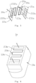
FIG. 1 is a perspective view, in a schematic form, showing a structure of an atomization assembly according to some embodiments of the present invention; -
FIG. 2 is a perspective view, in a schematic form, showing the structure of the atomization assembly ofFIG. 1 with a bottom facing upward; -
FIG. 3 is a perspective view, in an exploded form, showing the structure of the atomization assembly ofFIG. 1 ; -
FIG. 4 is a cross-sectional view, in a schematic form, taken along line A-A ofFIG 1 , showing the structure of the atomization assembly ofFIG. 1 ; -
FIG. 5 is a perspective view, in a schematic form, showing a structure of a heating body of an atomization assembly according to some other embodiments of the present invention; -
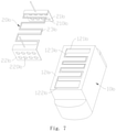
FIG. 6 is a perspective view, in a schematic form, showing a structure of an atomization assembly according to some additional embodiments of the present invention, with a bottom facing upward; -
FIG. 7 is a perspective view, in an exploded form, showing the structure of the atomization assembly ofFIG. 6 ; -
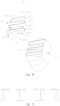
FIG. 8 is a perspective view, in a schematic form, showing a structure of a heating body of an atomization assembly according to some further additional embodiments of the present invention; and -
FIG. 9 is a cross-sectional view, in a schematic form, showing the structure of the heating body of the atomization assembly shown inFIG. 8 . - A more detailed illustration and clear and complete description is provided below for a specific structure, a manufacturing method, and efficacy of the present invention, with reference to the instant embodiment and the attached drawings together. Reference is now made to the attached drawings, in which similar reference signs are used to indicate the same structural components of the present invention or features of the drawings.
-
FIGS. 1-3 show anatomization assembly 1 according to some embodiments of the present invention. Theatomization assembly 1 is usable in an electronic atomization device, such as an electronic cigarette, for heating and atomizing a liquid medium, such as cigarette liquid. Theelectronic atomization device 1 comprises a porousceramic matrix 10, aheating body 20, and twoelectrode wires 30. The porousceramic matrix 10 is provided for sucking in and conducting the liquid medium. Theheating body 20 is mounted on the porousceramic matrix 10 for heating and atomizing the liquid medium sucked in by the porousceramic matrix 10. In some embodiments, theheating body 20 is integrally formed on the porousceramic matrix 10 as one piece by means of sintering, in order to make connection between the two more secured and also to make the effect of atomization better. It is appreciated that in some embodiments, porous matrixes of other forms may be used to substitute the porous ceramic matrix. The twoelectrode wires 30 are respectively soldered to two ends of theheating body 20. In some embodiments, theelectrode wires 30 may be omitted and two electrode contact points or portions of an alloy plate of thealloy heating body 20 may take the role of electrodes as a substitute for the above-described twoelectrode wires 30. - The porous
ceramic matrix 10 is generally in the form of a rectangular cuboid and comprises aliquid suction face 11 located on a top thereof and anatomization face 12 located on a bottom thereof and opposite to theliquid suction face 11. Theliquid suction face 11 is configured for contacting with the liquid medium in order to suck the liquid medium into the porousceramic matrix 10. The atomization face 12 is configured for contacting with theheating body 20 to allow the liquid medium in the porousceramic matrix 10 to be heated and atomized by theatomization face 12. It is appreciated that the arrangement of theliquid suction face 11 and theatomization face 12 is not limited to being opposite to each other, and in certain circumstances, it is possible to have two arranged adjacent to each other. - In some embodiments, the porous
ceramic matrix 10 is made of a diatomite ceramic material. Diatomite ceramic undergoes a phase change from α-cristobalite to β-cristobalite within a predetermined range of temperature, such as in the range of 180°C to 270°C. Such a phase change causes a certain amount of deformation of diatomite ceramic within a predetermined temperature range, meaning possession of a predetermined thermal expansion coefficient. Specifically, adjusting the content of diatomite in diatomite ceramic may control the thermal expansion coefficient thereof in a predetermined range, 18-45*10-6/°C. Through adjusting the content of diatomite, the porousceramic body 10 is made to have a thermal expansion coefficient thereof greater than or equal to a thermal expansion coefficient of theheating body 20, so as to prevent thealloy heating body 20 embedded in the porousceramic body 10 from detaching from the porousceramic body 10 due to warpage and deformation. Theheating body 20 that detaches from the porousceramic body 10 would suffer dry burning due to being not kept in contact with the cigarette liquid and such dry burning would lead to localized excessively high temperature in the heating body, fusing broken the heating body. On the other hand, the high temperature resulting from the dry burning may cause chemical reaction of the cigarette liquid that may generate harmful substance entraining air to get into human body to cause damage to human health. In some embodiments, theliquid suction face 11 is recessed in a direction toward theatomization face 12 in order to form a recessedcavity 110. The recessedcavity 110 may, on one hand, increase a surface area of the liquid suction face, and, on other hand, reduce a distance from theatomization face 12 to theliquid suction face 11 in order to increase a liquid transmission efficiency. In some embodiments, theatomization face 12 is planar and comprises a first embeddinggroove 121 and a second embeddinggroove 122 that are arranged parallel and spaced from each other to respectively receive a first fixingpart 21 and a second fixingpart 22 of theheating body 20 to fix therein. In some embodiments, the first embeddinggroove 121 and the second embeddinggroove 122 are parallel to each other in a lengthwise direction and are perpendicular to theatomization face 12 in a depth direction. It is appreciated that the first embeddinggroove 121 and the second embeddinggroove 122 are not limited to being in the atomization face. - In some embodiments, the porous
ceramic matrix 10 may further comprise afirst step 13 and asecond step 14. Thefirst step 13 and thesecond step 14 are respectively formed on two opposite sides of the porousceramic matrix 20 to facilitate mounting of the porousceramic matrix 10 in the electronic atomization device. - In some embodiments, the
heating body 20 may comprise the first fixingpart 21, the second fixingpart 22, and aheating part 23. The first fixingpart 21 and the second fixingpart 22 are respectively connected to two ends of theheating part 23 and are extended in a direction toward one side of theheating part 23 for being respectively fixed in the first embeddinggroove 121 and the second embeddinggroove 121 of theatomization face 12. In some embodiments, the first fixingpart 21, the second fixingpart 22, and theheating part 23 are integrally formed, as one piece, of a metal plate through etching or stamping. Theheating part 23 is configured for tightly contacting theatomization face 12 to have the liquid medium in the porousceramic matrix 10 heated and thus atomized on theatomization face 12. Theheating part 23 is bent, generally in a S-shaped form, and disposed on a plane to form a heating net, which, on one hand, enables uniformly heating of theheating part 23 to reduce non-uniformity of stress resulting from non-uniform heating of theheating body 20 and thus prolong the service life of theheating body 20, and, on other hand, enables uniform atomization of the liquid medium by theatomization face 12. - In some embodiments, the
heating body 20 is made of a metal plate, such as a nickel-chromium alloy plate, an iron-chromium-aluminum alloy plate, and a stainless steel plate, and preferably, theheating body 20 is made of an iron-chromium-aluminum (FeCrAl) alloy material. The iron-chromium-aluminum (FeCrAl) alloy material may form a dense aluminum oxide film on a surface thereof at a high temperature in vacuum of 0.2-10Pa, which prevents the iron-chromium-aluminum (FeCrAl) alloy material from being further oxidized. Specifically, theheating body 20 that is made of the iron-chromium-aluminum (FeCrAl) alloy material would have a surface thereof oxidized to form a dense aluminum oxide film during an operation of being integrally formed with the ceramic paste to form theatomization assembly 1. Preferably, the conditions of being oxidized to form the dense aluminum oxide film are: vacuum of 0.2-10Pa and temperature of 1100°C-1400°C. The dense aluminum oxide film may effectively prevent theheating body 20 from being oxidized through contacting the cigarette liquid medium, which may cause a chemical reaction for generating heavy metals so as to inhale, with atomized gas, into human lungs to influence the human health. - The
heating body 20 preferably comprises an S-shaped net-like heating part 23, which is of a compact structure of which internal microscopic structure is uniformly distributed and electrical paths are excellently conducting so that the net-like heating part 23 has a uniform temperature distribution during heating, without causing excessive stress concentration. Further, when the net-like heating part 23 is made of metal, it shows excellent toughness and does not cause failure through defects and cracking, and has excellent stability of resistance and requires no inspection for outside flaws and dry burning performance, allowing for prolongation of service life of theheating body 20, operability under high power, and stable resistance facilitating design for circuit controlling temperature. - In some embodiments, as the
heating body 20 is made of a metal plate by means of for example stamping, the fabrication cycle is short and the cost is low, allowing for realization of integral formation of theheating body 20 and the porousceramic matrix 10 through one sintering operation, the operation being simple and cost being low. - In some embodiments, the
heating part 23 is formed as a net-like configuration by means of etching processing, allowing the film width and film thickness to be slender and thin, and during the fabrication, theheating part 23 may be embedded in the porousceramic matrix 10, meaning a plane defined by theheating part 23 of theheating body 20 is generally flush with the atomization face of the porousceramic matrix 10 or slightly embedded in the atomization face, but does not affect atomization, so as to efficiently impregnate with a liquid medium such as the cigarette liquid, and achieve an effect of fast supply of the liquid in an application to electronic cigarettes, enhancing matchability with cigarette liquid, making flavor restoration high, realizing extended service life and high power. - In some embodiments, the
metal heating body 20 is embedded in the porousceramic matrix 10 and is excellently combined with the porousceramic matrix 10. Further, theheating body 20 is arranged in a net-like form that shows elasticity, allowing for easy release of stress during thermal oscillation resulting from vaping and being not easy to detach. - In some embodiments, the
heating body 20 is integrally formed with the porousceramic matrix 10 as one piece, with theheating part 23 thereof tightly attached to the atomization face 12 (meaning being laid flat on the atomization face 12). In some embodiments, the first fixingpart 21 and the second fixingpart 22 are each in the form of a rectangular plate embedded in the porousceramic matrix 10 and are respectively formed with a plurality of first fixingholes 210 and second fixing holes 220. Jointly referring toFIG. 4 , the first fixingholes 210 and the second fixing holes 220 are configured to receive a material of the porousceramic matrix 10 to extend therethrough during a forming process, in order to form fixing pillars (not labeled) located in the first embeddinggroove 121 and the second embeddinggroove 122 for locking the first fixingpart 21 and the second fixingpart 22 in the porousceramic matrix 10, so as to make theheating body 20 and the porousceramic matrix 10 more securely fixed after being integrally formed together. In some embodiments, the first fixingpart 21 and the second fixingpart 22 are each perpendicular to the plane on which theheating part 23 is located. In some embodiments, theheating part 23 may further comprise afirst soldering part 231 and asecond soldering part 232, thefirst soldering part 231 being respectively located on two ends of theheating part 23 to respectively connect with the first fixingpart 21 and the second fixing part. In some embodiments, thefirst soldering part 231 and thesecond soldering part 232 are each of a rectangular shape having a width greater than a width of heating filaments in a middle of theheating part 23. The twoelectrode wires 30 are respectively soldered to thefirst soldering part 231 and thesecond soldering part 231 to respectively and electrically connect with positive and negative terminals of a power source. - In some embodiments, the
heating body 20 may further comprise two first positioning holes formed in the first electrode and two second positioning holes formed in the second electrode. The first positioning holes and the second positioning holes are fit to first positioning pegs and second positioning pegs inside a forming cavity for positioning or fixing the heating body and to prevent the heating body from shifting due to impact by ceramic paste in the operation of being integrally formed with the porous ceramic blank. - A manufacturing process for the above-described
atomization assembly 1 may include the following steps: - Step One: providing a porous ceramic paste and applying an etching operation to form the above-described
heating body 20. - Step Two: respectively positioning a first fixing
end 231 and asecond fixing end 232 of theheating body 20 at predetermined locations in a forming cavity for a forming operation. - Step Three: injecting the ceramic paste into the forming cavity in which the
heating body 20 is positioned and waiting for the ceramic paste to cure and shape, so that the cured and shaped ceramic paste forms a blank of aporous matrix 10. Thefirst fixing end 231 and the second fixingend 232 of theheating body 20 are each embedded in the blank of theporous matrix 10, and a material of the porous matrix extends through first fixingholes 110 and second fixing holes 120. - Step Four: removing the blank that carries the
heating body 20 out of the forming cavity to subject to high temperature sintering, such that the blank is sintered to form the porousceramic matrix 10, and theheating body 20 is integrally combined in the porousceramic matrix 10 to form the above-describedatomization assembly 1. - In some embodiments, a material for the
heating body 20 provided in Step One includes a metallic material that features fast temperature rise and uniform heat generation, such as one of the following materials, a nickel-chromium alloy, an iron-chromium-aluminum alloy, stainless steel, pure nickel, titanium, and nickel iron. In some embodiments, the material of theheating body 20 in Step One is an iron-chromium-aluminum (FeCrAl) alloy material. - In some embodiments, in Step Two, the positioning of the heating body is achieved by having two first positioning holes and two second positioning holes fit to positioning pillars inside the forming cavity.
- In some embodiments, the
heating body 20 includes a one-piece metal part, which is manufactured as being integrally formed by adopting one or more of a laser cutting technique, a stamping technique, and an etching technique, or alternatively, theheating body 20 may have parts that are made separately and is formed through bonding together by applying welding or other bonding techniques. - In some embodiments, in Step Two, the
heating body 20 that features fast temperature rise and uniform heat generation is positioned in the forming cavity and the ceramic paste that is in a melt form and is uniformly stirred is poured into the forming cavity in which theheating body 20 is positioned at a predetermined location. - In some embodiments, before high temperature sintering of Step Four, an additional step is provided: removing out the cured and shaped ceramic paste to obtain a ceramic heating body blank, and subjecting the ceramic heating body blank to glue-removing sintering in an oxygen-containing environment so as to have vaporize a bonding agent in a high temperature to thereby obtain a glue-removed blank. Preferably, a temperature for the above sintering is arranged at 200°C-800°C.
- In some embodiments, the high temperature sintering of Step Four is performed with vacuum high temperature sintering, and preferable vacuum is 0.2-10Pa. High temperature sintering performed in such a vacuum (0.2-10Pa) environment allows the alloy material of the
heating body 20 that is formed on the porousceramic matrix 10 to form a dense oxide film. Particularly, for theheating body 20 that is made of a FeCrAl alloy material, the densification effect is even better, and the dense oxide film can effectively prevent theheating body 20 from chemically reacting with a liquid, such as the cigarette liquid, to cause precipitation of heavy metals to entrain with atomization gas into human lungs to affect human health. - In some embodiments, the temperature for the high temperature sintering of Step Four is 1100°C-1400°C.
-
FIG. 5 shows a heating body 20a of an atomization assembly according to some other embodiments of the present invention. In some embodiments, the heating body 20a may comprise afirst fixing part 21a, asecond fixing part 22a, and aheating part 23a. Thefirst fixing part 21a and thesecond fixing part 22a are respectively connected to two ends of theheating part 23a and are extended in a direction toward one side of theheating part 23a. - The
heating part 23a is bent, generally in an S-shaped form, and is disposed, in a tight engagement manner, on theatomization face 12, but is not securely fixed thereto. In this way, theheating part 23a is provided with a space for movement for thermal expansion and contraction, in order to reduce the tensile stress thereof to thereby prolong the service life of the heating body 20a. In some embodiments, the first fixingpart 21a and thesecond fixing part 22a are each in the form of a rectangular plate, and are respectively formed with a plurality of first fixingholes 210a and second fixingholes 220a. Jointly referring toFIG. 4 , the first fixingholes 210a and the first fixingholes 220a are configured to receive a material of the porousceramic matrix 10 to extend therethrough during a forming process, in order to make the heating body 20a and the porousceramic matrix 10 more securely fixed after being integrally formed together. In some embodiments, the first fixingpart 21a and thesecond fixing part 22a are each perpendicular to the plane on which theheating part 23a is located. - In some embodiments, the
heating part 23a may further comprises afirst soldering part 231a and asecond soldering part 232a. Thefirst soldering part 231a is connected and fixed between the first fixingpart 21a and theheating part 23a, and thesecond soldering part 232a is connected and fixed between thesecond fixing part 22a and theheating part 23a, so that theheating part 23a is arranged to receive each of the first fixingpart 21a and thesecond fixing part 22a to connect thereto and to generate heat jointly with theheating part 23a, to allow the liquid medium in the porousceramic matrix 10 to be heated and atomized on theatomization face 12. In some embodiments, thefirst soldering part 231a and thesecond soldering part 232a are each of a rectangular shape having a surface area generally corresponding to that of the fixing parts, for having the heating body securely fixed thereto without easily breaking. - In some embodiments, the heating body 20a may further comprise two
electrode wires 30a. The twoelectrode wires 30a are respectively mounted on thefirst soldering part 231a and thesecond soldering part 231a and are respectively perpendicular to thefirst soldering part 231a and thesecond soldering part 232a for electrical connection with positive and negative terminals of a power source. - In some embodiments, the first fixing
part 21a and thesecond fixing part 22a of the heating body 20a are each of a shape of trapezoid, wherein the trapezoid short-base portions of the two are located close to theheating part 23a, while the trapezoid long-base portions are located distant from theheating part 23a, namely the first fixingpart 21a and thesecond fixing part 22a each comprise a large-size portion that is distant from theheating part 23a and a small-size portion that is close to theheating part 23a. Such a structural arrangement allows the first fixingpart 21a and thesecond fixing part 22a not to readily detach when integrally embedded in the porous matrix. -
FIGS. 6 and7 show anatomization assembly 1b according to some additional embodiments of the present invention. Theelectronic atomization device 1b may also comprise a porousceramic matrix 10b and aheating body 20b. Theheating body 20b is integrally formed on the porousceramic matrix 10b by means of sintering. Theheating body 20b may comprise afirst fixing part 21b, a second fixing part 22b, and aheating part 23b. Thefirst fixing part 21b and the second fixing part 22b are respectively connected to two ends of theheating part 23b and are extended in a direction toward one side of theheating part 23b. The porousceramic matrix 10b comprises anatomization face 12b, and a first embeddinggroove 121b, a second embeddinggroove 122b, and a third embeddinggroove 123b are formed in theatomization face 12b. Theheating body 20b, the first fixingpart 21b, the second fixing part 22b, and theheating part 23b are respectively fit into and embedded in the first embeddinggroove 121b, the second embeddinggroove 122b, and the third embeddinggroove 123b. As shown in the drawings, the third embeddinggroove 123b has a depth that corresponds to a thickness of theheating part 23b, so that when theheating part 23b is fit therein, an outside surface of theheating part 23b is flush with theatomization face 12b. It is appreciated that in some embodiments, it is possible to have the depth of the third embeddinggroove 123b less than or greater than the thickness of theheating part 23b to suit for different needs. In some embodiments, the first fixingpart 21b and the second fixing part 22b are respectively formed with a plurality of the first fixing holes 210b and second fixingholes 220b. -
FIG. 8 shows a heating body 20c of an atomization assembly according to some further additional embodiments of the present invention. In some embodiments, the heating body 20c comprises aheating part 23c and a first electrode part 24c and asecond electrode part 25c connected to two ends of the heating part. Theheating part 23c is bent, generally in an S-shaped form, and is disposed, in a tight engagement manner, on theatomization face 12, but is not securely fixed thereto. In this way, theheating part 23c is provided with a space for movement for thermal expansion and contraction, in order to reduce the tensile stress thereof to thereby prolong the service life of the heating body 20c. The first electrode part 24c and thesecond electrode part 25c are respectively connected to two ends of theheating part 10, that is connecting to two free ends of the S-shaped heating part 2c0. - In some embodiments, the heating part connected between the first electrode part 24c and the
second electrode part 25c is such that line width is gradually increased from the connection thereof with the first electrode and the second electrode toward a middle of the heating part. This could balance temperature of the entire heating part 20c, ensuring temperature distribution uniformity of the entirety of the heating part. - In some embodiments, as shown in
FIG. 9 , heating wires of theheating part 23c have a cross-section exhibiting a shape of trapezoid, meaning a surface of theheating part 23c at the end that is in contact with or embedded in the atomization face 12c has a larger surface area (being on the long base of the trapezoidal cross-section), while a surface of the heating part that is opposite to the atomization face 12c has a smaller surface area (being on the short base of the trapezoidal cross-section). Such a trapezoidal arrangement helps liquid to climb upward on one hand, and also helps improve embeddability of the heating part 20c in the porous ceramic matrix 10c to prevent warpage of the heating part. The cross-sectional shape of the heating wires of theheating part 23c is not limited to such a trapezoidal shape and may be a semi-cylindrical shape or other shapes based on the requirement that the surface areas on the top and bottom surfaces are different. - In some embodiments, the first electrode part 24c and the
second electrode part 25c are each in the form of a rectangular plate, and are respectively formed with a plurality of first positioning holes 240c andsecond positioning holes 250c, which are fit to corresponding positioning pegs inside a forming cavity in a one-piece forming process, in order to prevent the heating body from shifting due to impact by ceramic paste. - In some embodiments, the heating body 20c may further comprise a plurality of first fixing
part 21c and a plurality of second fixingpart 22c. The plurality of first fixingpart 21c are respectively arranged on two opposite short-edged sides of the first electrode part 24c and two opposite short-edged sides of thesecond electrode part 25c and are extended in a direction toward one side of theheating part 23c for being integrally formed with the porous ceramic body blank to fix the heating body 20c. In some embodiments, the plurality of first fixingpart 21c and the plurality of second fixingpart 22c may be respectively formed on ends of long-edge sides of the first electrode part 24c and thesecond electrode part 25c that are distant from theheating part 23c. The plurality of second fixingpart 22c are respectively connected to side edges of theheating part 23c and extended in a direction toward one side of theheating part 23c for being integrally formed with the porous ceramic body blank to fix the heating body 20c. In some embodiments, as shown inFIG. 8 , thesecond fixing parts 22c are each of a T-shape, and one end connected to theheating part 23c is a lower end of the T-shape for facilitating fixing of the heating body 20c on one hand and for reducing loss of heat on other hand. - In some embodiments, the first fixing
parts 21c may comprises a plurality of first fixingholes 210c formed therein. The first fixingholes 210c are arranged to receive a material of the porousceramic matrix 10 to extend therethrough in a forming process, in order to make the heating body 20c and the porous ceramic matrix 10c more securely fixed after being integrally formed together. In some embodiments, the first fixingparts 21c are of a shape of trapezoid, and a short-base portion of the trapezoid is located close to theheating part 23c, while a long-base portion of the trapezoid is located distant from theheating part 23c, namely the first fixingparts 21c each comprise a large-size portion that is distant from theheating part 23c and a small-size portion that is close to theheating part 23c. Such a structural arrangement allows the first fixingparts 21c not to readily detach when integrally embedded in the porous matrix. - In some embodiments, the first fixing
parts 21c and thesecond fixing parts 22c are each perpendicular to a plane on which theheating part 23c in located. - For some embodiments, the above description provides only some specific examples of the present invention. However, the present invention is not limited to the description, and variations that can be contemplated by those skilled in the field fall in the protection scope of the present invention.
Claims (15)
- An atomization assembly, comprising a porous matrix and a heating body, the porous matrix comprising an atomization face, characterized in that the heating body comprises a heating part and at least one fixing part connected to the heating part, the at least one fixing part being embedded in the porous matrix so as to have the heating body mounted on the porous matrix, the heating part being arranged to correspond to the atomization face.
- The atomization assembly according to claim 1, characterized in that the heating body is integrally formed on the porous matrix by means of sintering, and the porous matrix is a porous ceramic matrix.
- The atomization assembly according to claim 2, characterized in that the porous ceramic matrix is made of a diatomite ceramic material.
- The atomization assembly according to claim 1, characterized in that the at least one fixing part is formed with at least one fixing hole, and during a process of integrally forming, the porous matrix penetrates into the at least one fixing hole to form at least one fixing pillar that corresponds to the at least one fixing hole.
- The atomization assembly according to claim 1, characterized in that the at least one fixing part comprises a large-size portion distant from the heating part and a small-size portion adjacent to the heating part.
- The atomization assembly according to claim 5, characterized in that the at least one fixing part is of a shape of trapezoid, wherein a short-base portion of the trapezoid of the at least one fixing part is located adjacent to the heating part, and a long-base portion of the trapezoid is located distant from the heating part.
- The atomization assembly according to claim 1, characterized by further comprising at least one second fixing part connected to the heating part, the at least one second fixing part being of a T-shape, the heating part being connected to a small end of the T-shape.
- The atomization assembly according to claim 1, characterized in that the heating body is made of an iron-chromium-aluminum (FeCrAl) alloy material.
- The atomization assembly according to claim 8, characterized in that the heating part comprises a heating net which comprises a heating wire, the heating wire having a cross-section that is of a shape of trapezoid, a surface on which a long base of the trapezoid is located being embedded in the atomization face, a short base of the trapezoid being slightly higher than the atomization face or being flush with the atomization face.
- The atomization assembly according to any one of claims 1-9, characterized in that the heating body further comprises a first electrode part and a second electrode part connected to two ends of the heating part, the first electrode part and the second electrode part being in the form of a rectangular plate; the at least one fixing part comprises a first fixing part and a second fixing part that are spaced from each other, the first fixing part and the second fixing part being respectively connected with the first electrode part and the second electrode part.
- The atomization assembly according to claim 10, characterized in that the heating part comprises a first soldering part and a second soldering part located on two ends thereof; the atomization assembly further comprises two electrode wires, the two electrode wires being respectively and electrically connected with the first soldering part and the second soldering part.
- The atomization assembly according to any one of claims 1-9, characterized in that the heating part is embedded in or laid flat on the atomization face; the porous matrix comprises a liquid suction face opposite to the atomization face, the liquid suction face being recessed in a direction toward the atomization face to form a recessed cavity.
- An electronic atomization device, characterized by comprising the atomization assembly according to any one of claims 1-12.
- A manufacturing method for the atomization assembly according to any one of claims 1-13, characterized by comprising the following steps:Step One: providing a porous ceramic paste and the heating body;Step Two: forming a porous ceramic blank that is combined with the heating body, wherein the porous ceramic blank comprises a surface that corresponds to the atomization face after formation; the fixing parts of the heating body are embedded in the porous ceramic blank, and the heating part corresponds to the surface that corresponds to the atomization face after formation;Step Three: subjecting the porous ceramic blank that carries the heating body to high temperature sintering under conditions of vacuum being 0.2-10Pa and a temperature being 1100°C-1400°C.
- The manufacturing method for the atomization assembly according to claim 14, characterized in that a step is added between Step Three and Step Four and comprises: subjecting the porous ceramic blank to glue-removing sintering in an oxygen-containing environment at a temperature of 200°C-800°C to obtain a glue-removed porous ceramic blank.
Applications Claiming Priority (2)
| Application Number | Priority Date | Filing Date | Title |
|---|---|---|---|
| CN201910411426.9A CN110301674A (en) | 2019-05-16 | 2019-05-16 | The manufacturing method of electronic atomization device and its atomizing component and atomizing component |
| PCT/CN2019/127194 WO2020228330A1 (en) | 2019-05-16 | 2019-12-20 | Electronic atomization device, atomization assembly thereof and manufacturing method of atomization assembly |
Publications (3)
| Publication Number | Publication Date |
|---|---|
| EP3960011A1 true EP3960011A1 (en) | 2022-03-02 |
| EP3960011A4 EP3960011A4 (en) | 2022-07-20 |
| EP3960011B1 EP3960011B1 (en) | 2023-05-10 |
Family
ID=68074594
Family Applications (1)
| Application Number | Title | Priority Date | Filing Date |
|---|---|---|---|
| EP19928734.3A Active EP3960011B1 (en) | 2019-05-16 | 2019-12-20 | Atomization assembly and manufacturing method of atomization assembly |
Country Status (4)
| Country | Link |
|---|---|
| US (1) | US12121064B2 (en) |
| EP (1) | EP3960011B1 (en) |
| CN (6) | CN110301674A (en) |
| WO (1) | WO2020228330A1 (en) |
Cited By (1)
| Publication number | Priority date | Publication date | Assignee | Title |
|---|---|---|---|---|
| EP4289297A4 (en) * | 2021-02-02 | 2024-04-03 | Shenzhen Smoore Technology Limited | HEATING COMPONENT AND ELECTRONIC ATOMIZATION DEVICE |
Families Citing this family (42)
| Publication number | Priority date | Publication date | Assignee | Title |
|---|---|---|---|---|
| CN110301674A (en) | 2019-05-16 | 2019-10-08 | 深圳麦克韦尔科技有限公司 | The manufacturing method of electronic atomization device and its atomizing component and atomizing component |
| CN211099776U (en) * | 2019-10-14 | 2020-07-28 | 深圳市华诚达精密工业有限公司 | Multi-core porous liquid guide material heating atomization core and assembly |
| CN111000293B (en) * | 2019-12-05 | 2025-05-27 | 东莞市陶陶新材料科技有限公司 | Electronic cigarette atomization core and preparation method thereof |
| CN111011934B (en) * | 2019-12-30 | 2025-04-11 | 深圳麦克韦尔科技有限公司 | Heating components, atomizers and electronic atomization devices |
| CN111035070A (en) * | 2020-01-08 | 2020-04-21 | 深圳麦时科技有限公司 | Aerosol generating device and heating assembly thereof |
| CN111109666A (en) * | 2020-01-17 | 2020-05-08 | 深圳麦克韦尔科技有限公司 | Electronic atomization device, atomization assembly thereof and manufacturing method of atomization assembly |
| CN111248514A (en) * | 2020-03-20 | 2020-06-09 | 云南中烟工业有限责任公司 | A kind of carbon nano heating element for electric heating cigarette smoking set |
| CN111528529B (en) * | 2020-04-30 | 2022-07-12 | 四川三联新材料有限公司 | Heating element of heating appliance and preparation method thereof |
| CN111436666A (en) * | 2020-05-11 | 2020-07-24 | 深圳市华诚达精密工业有限公司 | Porous liquid-guiding heating atomization assembly with supporting shell and preparation method thereof |
| CN111887499A (en) * | 2020-06-29 | 2020-11-06 | 阿特麦哲(东莞)科技有限公司 | Ceramic composite atomizing assembly and manufacturing method thereof |
| CN111887500A (en) * | 2020-06-29 | 2020-11-06 | 阿特麦哲(东莞)科技有限公司 | Ceramic composite atomizer and manufacturing method thereof |
| CN111728277A (en) * | 2020-07-07 | 2020-10-02 | 深圳伊卡普科技有限公司 | A kind of microporous ceramic atomizing core and its manufacturing method |
| CN112315027B (en) * | 2020-08-31 | 2025-03-21 | 深圳麦克韦尔科技有限公司 | An electronic atomization device and its atomizer and atomization core |
| CN112316259A (en) * | 2020-10-27 | 2021-02-05 | 深圳市康泓威科技有限公司 | Electronic atomization equipment that is easy to assemble and easy to inject |
| CN114617299A (en) * | 2020-12-11 | 2022-06-14 | 常州市派腾电子技术服务有限公司 | Atomizing core, atomizer, aerosol generating device and atomizing core processing method |
| CN113142676B (en) * | 2020-12-31 | 2025-05-02 | 深圳麦克韦尔科技有限公司 | An electronic atomization device and its atomizer and atomization core |
| JP7624073B2 (en) * | 2020-12-31 | 2025-01-29 | 深▲せん▼麦克韋爾科技有限公司 | Electronic atomization device and its atomizer and atomization core |
| WO2022160136A1 (en) * | 2021-01-27 | 2022-08-04 | 深圳麦克韦尔科技有限公司 | Ceramic matrix and preparation method therefor, ceramic heating element and electronic atomization device |
| CN114804833A (en) * | 2021-01-27 | 2022-07-29 | 深圳麦克韦尔科技有限公司 | Ceramic substrate and preparation method thereof, ceramic heating element and electronic atomization device |
| CN113080528A (en) * | 2021-03-29 | 2021-07-09 | 凡品思(深圳)科技有限公司 | Finished product core, atomizer and electron cigarette |
| CN215381464U (en) * | 2021-06-03 | 2022-01-04 | 比亚迪精密制造有限公司 | Electronic cigarette cartridges and electronic cigarettes |
| US20240180249A1 (en) * | 2021-06-03 | 2024-06-06 | Shenzhen Huachengda Precision Industry Co. Ltd. | Close-Packed Heating Mechanism and Atomization Device Comprising The Same |
| WO2023272646A1 (en) * | 2021-06-30 | 2023-01-05 | 深圳市华诚达精密工业有限公司 | Heating mechanism for heating in stages, and atomization apparatus using same |
| KR102716762B1 (en) * | 2021-07-28 | 2024-10-11 | 주식회사 케이티앤지 | Wick-heater assembly and aerosol generating device including the same |
| WO2023045600A1 (en) * | 2021-09-22 | 2023-03-30 | 常州市派腾电子技术服务有限公司 | Atomizing core, atomizer, aerosol generating device, and atomizing core processing method |
| CN115868674A (en) * | 2021-09-30 | 2023-03-31 | 深圳市新宜康科技股份有限公司 | Ceramic heating element and atomizing core |
| CN113841938A (en) * | 2021-10-29 | 2021-12-28 | 惠州市新泓威科技有限公司 | Atomizing core with atomizing groove |
| CN114762537A (en) * | 2021-12-02 | 2022-07-19 | 深圳麦克韦尔科技有限公司 | Heating element module, preparation method thereof, packaging module and electronic atomization device |
| WO2022179229A1 (en) * | 2021-12-02 | 2022-09-01 | 深圳麦克韦尔科技有限公司 | Heating element module and preparation method therefor, packaging module and electronic atomization device |
| CN116439419A (en) * | 2022-01-10 | 2023-07-18 | 深圳市卓力能技术有限公司 | Heating component |
| WO2023137705A1 (en) * | 2022-01-21 | 2023-07-27 | 深圳市华诚达精密工业有限公司 | Heating and atomization assembly, and heating and atomization device and electronic atomizer thereof |
| CN115245210B (en) * | 2022-05-09 | 2025-08-19 | 深圳市赛尔美电子科技有限公司 | Method for assembling atomizer |
| CN114668182A (en) | 2022-03-31 | 2022-06-28 | 海南摩尔兄弟科技有限公司 | Electronic atomizing device and atomizing core thereof |
| CN115281385A (en) * | 2022-07-29 | 2022-11-04 | 深圳麦克韦尔科技有限公司 | Electronic atomization device and its atomizer, atomizing core and manufacturing method of atomizing core |
| CN115363270A (en) * | 2022-07-29 | 2022-11-22 | 深圳麦克韦尔科技有限公司 | Heating element and electronic atomization device |
| US20240090570A1 (en) * | 2022-09-16 | 2024-03-21 | Shenzhen Aerosol Technology Research Co., Ltd. | Liquid-conducting atomization mechanism and electronic atomizer |
| CN116041087B (en) * | 2023-01-31 | 2024-05-14 | 深圳市赛尔美电子科技有限公司 | Porous carbon atomization matrix, preparation method, electronic atomization core and electronic atomization device |
| CN116114927A (en) * | 2023-03-28 | 2023-05-16 | 深圳市卓力能技术有限公司 | Electronic atomization device and atomization assembly thereof |
| CN117655333A (en) * | 2023-11-13 | 2024-03-08 | 深圳市你我网络科技有限公司 | Porous metal body and preparation method thereof, atomizer heating element and preparation method thereof |
| CN117655332A (en) * | 2023-11-13 | 2024-03-08 | 深圳市你我网络科技有限公司 | Porous metal body and preparation method thereof, atomizer heating element and preparation method thereof |
| CN120154144A (en) * | 2023-12-16 | 2025-06-17 | 尼科创业贸易有限公司 | A heating component of an aerosol supply system and an aerosol supply system |
| CN117945783B (en) * | 2024-01-09 | 2026-03-10 | 深圳市吉迩科技有限公司 | Preparation method of ceramic atomizing core and ceramic atomizing core |
Family Cites Families (26)
| Publication number | Priority date | Publication date | Assignee | Title |
|---|---|---|---|---|
| JP2560031B2 (en) * | 1987-05-26 | 1996-12-04 | マツダ株式会社 | Exhaust gas sensor |
| US5665262A (en) * | 1991-03-11 | 1997-09-09 | Philip Morris Incorporated | Tubular heater for use in an electrical smoking article |
| JP3127509B2 (en) * | 1991-08-23 | 2001-01-29 | 株式会社ブリヂストン | Ceramic porous body |
| JPH07217885A (en) * | 1994-02-07 | 1995-08-18 | Isuzu Ceramics Kenkyusho:Kk | Ceramic heater |
| JP2004087476A (en) * | 2002-06-26 | 2004-03-18 | Okazaki Mfg Co Ltd | Structure of hot plate for heating wafer and method of fixing electrodes on hot plate |
| TWI543475B (en) * | 2012-11-30 | 2016-07-21 | 鴻海精密工業股份有限公司 | Electrical connector |
| GB2515992A (en) * | 2013-03-22 | 2015-01-14 | British American Tobacco Co | Heating smokeable material |
| CN105917734B (en) * | 2014-02-10 | 2019-09-13 | 菲利普莫里斯生产公司 | Fluid permeable heater assembly and method of assembly for use in aerosol generating systems |
| KR102596180B1 (en) * | 2015-04-13 | 2023-10-30 | 쥐.디 에스.피.에이. | Electric cartridge for electronic cigarette and method of manufacturing electric cartridge |
| CN105433441A (en) * | 2015-12-14 | 2016-03-30 | 深圳市合元科技有限公司 | Heating module, atomizer and electronic cigarette |
| CN105813815B (en) * | 2016-03-15 | 2018-06-12 | 惠州市吉瑞科技有限公司深圳分公司 | A kind of manufacturing method of heater and the molding machine of heater |
| MX2018014452A (en) * | 2016-05-31 | 2019-04-15 | Philip Morris Products Sa | Fluid permeable heater assembly for aerosol-generating systems and flat electrically conductive filament arrangement for fluid permeable heater assemblies. |
| KR20190017907A (en) * | 2016-06-27 | 2019-02-20 | 니뽄 다바코 산교 가부시키가이샤 | A flavor aspirator having a cartridge for a flavor aspirator and a cartridge for the flavor aspirator |
| PL3487324T3 (en) * | 2016-07-25 | 2021-05-31 | Philip Morris Products S.A. | Fluid permeable heater assembly with cap |
| CN206136341U (en) * | 2016-10-14 | 2017-04-26 | 宁波捷美进出口有限公司 | High -efficient heating structure |
| CN108208938A (en) * | 2017-12-27 | 2018-06-29 | 深圳市卓力能电子有限公司 | A kind of heater and preparation method |
| CN108158040B (en) * | 2018-01-03 | 2023-11-21 | 云南中烟工业有限责任公司 | A MEMS electronic cigarette chip that generates uniform heat and its manufacturing method |
| CN108185535B (en) * | 2018-02-13 | 2020-09-29 | 深圳麦克韦尔科技有限公司 | Electronic cigarette, heating assembly and heating body thereof |
| CN120226799A (en) * | 2018-06-07 | 2025-07-01 | 尤尔实验室有限公司 | Cartridges for evaporator devices |
| EP3850967B1 (en) * | 2018-09-10 | 2024-05-29 | Shenzhen Smoore Technology Limited | Electronic cigarette, atomization assembly, and atomization component for same |
| CN109608206B (en) * | 2018-11-14 | 2023-11-07 | 深圳市华诚达精密工业有限公司 | Heating element with heating net embedded on porous ceramic surface and preparation method thereof |
| CN109349681B (en) * | 2018-11-15 | 2021-09-03 | 深圳市合元科技有限公司 | Porous heating element, atomizer containing porous heating element and porous body preparation method |
| CN109380771B (en) * | 2018-11-19 | 2021-12-14 | 深圳麦克韦尔科技有限公司 | Electronic atomization device and atomization element thereof |
| CN109674094A (en) * | 2019-01-26 | 2019-04-26 | 深圳市合元科技有限公司 | Electronic smoke atomizer and electronic cigarette, atomizing component preparation method |
| CN210158019U (en) * | 2019-05-16 | 2020-03-20 | 深圳麦克韦尔科技有限公司 | Electronic atomization device and atomization assembly thereof |
| CN110301674A (en) * | 2019-05-16 | 2019-10-08 | 深圳麦克韦尔科技有限公司 | The manufacturing method of electronic atomization device and its atomizing component and atomizing component |
-
2019
- 2019-05-16 CN CN201910411426.9A patent/CN110301674A/en active Pending
- 2019-12-20 CN CN201911329421.8A patent/CN110881694B/en active Active
- 2019-12-20 CN CN202510544508.6A patent/CN120130703A/en active Pending
- 2019-12-20 EP EP19928734.3A patent/EP3960011B1/en active Active
- 2019-12-20 CN CN201911330811.7A patent/CN110973708B/en active Active
- 2019-12-20 WO PCT/CN2019/127194 patent/WO2020228330A1/en not_active Ceased
- 2019-12-20 CN CN201922340804.7U patent/CN211746932U/en active Active
- 2019-12-20 CN CN201911329429.4A patent/CN110946335B/en active Active
-
2021
- 2021-11-16 US US17/527,193 patent/US12121064B2/en active Active
Cited By (1)
| Publication number | Priority date | Publication date | Assignee | Title |
|---|---|---|---|---|
| EP4289297A4 (en) * | 2021-02-02 | 2024-04-03 | Shenzhen Smoore Technology Limited | HEATING COMPONENT AND ELECTRONIC ATOMIZATION DEVICE |
Also Published As
| Publication number | Publication date |
|---|---|
| US20220071290A1 (en) | 2022-03-10 |
| CN110973708A (en) | 2020-04-10 |
| EP3960011A4 (en) | 2022-07-20 |
| CN110881694B (en) | 2024-04-19 |
| WO2020228330A1 (en) | 2020-11-19 |
| CN110946335B (en) | 2024-11-19 |
| CN211746932U (en) | 2020-10-27 |
| CN120130703A (en) | 2025-06-13 |
| CN110881694A (en) | 2020-03-17 |
| CN110301674A (en) | 2019-10-08 |
| CN110946335A (en) | 2020-04-03 |
| EP3960011B1 (en) | 2023-05-10 |
| US12121064B2 (en) | 2024-10-22 |
| CN110973708B (en) | 2025-05-23 |
Similar Documents
| Publication | Publication Date | Title |
|---|---|---|
| EP3960011B1 (en) | Atomization assembly and manufacturing method of atomization assembly | |
| CN111109666A (en) | Electronic atomization device, atomization assembly thereof and manufacturing method of atomization assembly | |
| CN107113921B (en) | Electrostatic chuck heater | |
| CN212520793U (en) | Electronic atomization device and atomization assembly thereof | |
| WO2020057313A1 (en) | Flue-cured tobacco appliance and heating assembly thereof | |
| WO2001091166A1 (en) | Semiconductor manufacturing and inspecting device | |
| CN210158019U (en) | Electronic atomization device and atomization assembly thereof | |
| JP2019121432A (en) | Ceramic device | |
| CN119604974A (en) | Components for semiconductor manufacturing equipment | |
| WO2021013039A1 (en) | Heating assembly for aerosol generation device | |
| CN107548231A (en) | The preparation method of flexible base board and metal wiring connected structure | |
| JP2016184642A (en) | Member for semiconductor manufacturing device | |
| CN210094671U (en) | Atomization assembly for electronic cigarette | |
| JP4376141B2 (en) | Method for manufacturing surface acoustic wave device | |
| JP2001135715A (en) | Temperature measuring element and ceramic base material for semiconductor manufacturing apparatus | |
| JP5371728B2 (en) | Piezoelectric parts | |
| CN217658201U (en) | Heating element and electronic atomization device | |
| US20210333012A1 (en) | Ceramic heater for heating water in an appliance | |
| CN223979442U (en) | Aerosol generating device and heating element | |
| CN223979444U (en) | Aerosol generating device and heating element | |
| CN223979446U (en) | Aerosol generating device and its heating component | |
| JP2004177412A (en) | Temperature measurement element and ceramic base for semiconductor production device | |
| JP2001135869A (en) | Thermocouple and ceramic base material for semiconductor manufacturing device | |
| KR100794960B1 (en) | Hybrid heater manufacturing method | |
| KR20240123168A (en) | Method of assembling substrate supporting apparatus |
Legal Events
| Date | Code | Title | Description |
|---|---|---|---|
| STAA | Information on the status of an ep patent application or granted ep patent |
Free format text: STATUS: THE INTERNATIONAL PUBLICATION HAS BEEN MADE |
|
| PUAI | Public reference made under article 153(3) epc to a published international application that has entered the european phase |
Free format text: ORIGINAL CODE: 0009012 |
|
| STAA | Information on the status of an ep patent application or granted ep patent |
Free format text: STATUS: REQUEST FOR EXAMINATION WAS MADE |
|
| 17P | Request for examination filed |
Effective date: 20211112 |
|
| AK | Designated contracting states |
Kind code of ref document: A1 Designated state(s): AL AT BE BG CH CY CZ DE DK EE ES FI FR GB GR HR HU IE IS IT LI LT LU LV MC MK MT NL NO PL PT RO RS SE SI SK SM TR |
|
| A4 | Supplementary search report drawn up and despatched |
Effective date: 20220617 |
|
| RIC1 | Information provided on ipc code assigned before grant |
Ipc: A24F 40/46 20200101ALI20220611BHEP Ipc: C04B 35/622 20060101AFI20220611BHEP |
|
| DAV | Request for validation of the european patent (deleted) | ||
| DAX | Request for extension of the european patent (deleted) | ||
| REG | Reference to a national code |
Ref country code: DE Ref legal event code: R079 Ref document number: 602019028969 Country of ref document: DE Free format text: PREVIOUS MAIN CLASS: A24F0047000000 Ipc: A24F0040460000 |
|
| GRAP | Despatch of communication of intention to grant a patent |
Free format text: ORIGINAL CODE: EPIDOSNIGR1 |
|
| STAA | Information on the status of an ep patent application or granted ep patent |
Free format text: STATUS: GRANT OF PATENT IS INTENDED |
|
| RIC1 | Information provided on ipc code assigned before grant |
Ipc: A24F 40/70 20200101ALN20221115BHEP Ipc: A24F 40/10 20200101ALN20221115BHEP Ipc: A24F 40/46 20200101AFI20221115BHEP |
|
| RIC1 | Information provided on ipc code assigned before grant |
Ipc: A24F 40/70 20200101ALN20221118BHEP Ipc: A24F 40/10 20200101ALN20221118BHEP Ipc: A24F 40/46 20200101AFI20221118BHEP |
|
| INTG | Intention to grant announced |
Effective date: 20221207 |
|
| GRAS | Grant fee paid |
Free format text: ORIGINAL CODE: EPIDOSNIGR3 |
|
| GRAA | (expected) grant |
Free format text: ORIGINAL CODE: 0009210 |
|
| STAA | Information on the status of an ep patent application or granted ep patent |
Free format text: STATUS: THE PATENT HAS BEEN GRANTED |
|
| AK | Designated contracting states |
Kind code of ref document: B1 Designated state(s): AL AT BE BG CH CY CZ DE DK EE ES FI FR GB GR HR HU IE IS IT LI LT LU LV MC MK MT NL NO PL PT RO RS SE SI SK SM TR |
|
| REG | Reference to a national code |
Ref country code: GB Ref legal event code: FG4D |
|
| REG | Reference to a national code |
Ref country code: AT Ref legal event code: REF Ref document number: 1565846 Country of ref document: AT Kind code of ref document: T Effective date: 20230515 Ref country code: CH Ref legal event code: EP |
|
| REG | Reference to a national code |
Ref country code: DE Ref legal event code: R096 Ref document number: 602019028969 Country of ref document: DE |
|
| REG | Reference to a national code |
Ref country code: IE Ref legal event code: FG4D |
|
| P01 | Opt-out of the competence of the unified patent court (upc) registered |
Effective date: 20230428 |
|
| REG | Reference to a national code |
Ref country code: LT Ref legal event code: MG9D |
|
| REG | Reference to a national code |
Ref country code: NL Ref legal event code: MP Effective date: 20230510 |
|
| REG | Reference to a national code |
Ref country code: AT Ref legal event code: MK05 Ref document number: 1565846 Country of ref document: AT Kind code of ref document: T Effective date: 20230510 |
|
| PG25 | Lapsed in a contracting state [announced via postgrant information from national office to epo] |
Ref country code: SE Free format text: LAPSE BECAUSE OF FAILURE TO SUBMIT A TRANSLATION OF THE DESCRIPTION OR TO PAY THE FEE WITHIN THE PRESCRIBED TIME-LIMIT Effective date: 20230510 Ref country code: PT Free format text: LAPSE BECAUSE OF FAILURE TO SUBMIT A TRANSLATION OF THE DESCRIPTION OR TO PAY THE FEE WITHIN THE PRESCRIBED TIME-LIMIT Effective date: 20230911 Ref country code: NO Free format text: LAPSE BECAUSE OF FAILURE TO SUBMIT A TRANSLATION OF THE DESCRIPTION OR TO PAY THE FEE WITHIN THE PRESCRIBED TIME-LIMIT Effective date: 20230810 Ref country code: NL Free format text: LAPSE BECAUSE OF FAILURE TO SUBMIT A TRANSLATION OF THE DESCRIPTION OR TO PAY THE FEE WITHIN THE PRESCRIBED TIME-LIMIT Effective date: 20230510 Ref country code: ES Free format text: LAPSE BECAUSE OF FAILURE TO SUBMIT A TRANSLATION OF THE DESCRIPTION OR TO PAY THE FEE WITHIN THE PRESCRIBED TIME-LIMIT Effective date: 20230510 Ref country code: AT Free format text: LAPSE BECAUSE OF FAILURE TO SUBMIT A TRANSLATION OF THE DESCRIPTION OR TO PAY THE FEE WITHIN THE PRESCRIBED TIME-LIMIT Effective date: 20230510 |
|
| PG25 | Lapsed in a contracting state [announced via postgrant information from national office to epo] |
Ref country code: RS Free format text: LAPSE BECAUSE OF FAILURE TO SUBMIT A TRANSLATION OF THE DESCRIPTION OR TO PAY THE FEE WITHIN THE PRESCRIBED TIME-LIMIT Effective date: 20230510 Ref country code: PL Free format text: LAPSE BECAUSE OF FAILURE TO SUBMIT A TRANSLATION OF THE DESCRIPTION OR TO PAY THE FEE WITHIN THE PRESCRIBED TIME-LIMIT Effective date: 20230510 Ref country code: LV Free format text: LAPSE BECAUSE OF FAILURE TO SUBMIT A TRANSLATION OF THE DESCRIPTION OR TO PAY THE FEE WITHIN THE PRESCRIBED TIME-LIMIT Effective date: 20230510 Ref country code: LT Free format text: LAPSE BECAUSE OF FAILURE TO SUBMIT A TRANSLATION OF THE DESCRIPTION OR TO PAY THE FEE WITHIN THE PRESCRIBED TIME-LIMIT Effective date: 20230510 Ref country code: IS Free format text: LAPSE BECAUSE OF FAILURE TO SUBMIT A TRANSLATION OF THE DESCRIPTION OR TO PAY THE FEE WITHIN THE PRESCRIBED TIME-LIMIT Effective date: 20230910 Ref country code: HR Free format text: LAPSE BECAUSE OF FAILURE TO SUBMIT A TRANSLATION OF THE DESCRIPTION OR TO PAY THE FEE WITHIN THE PRESCRIBED TIME-LIMIT Effective date: 20230510 Ref country code: GR Free format text: LAPSE BECAUSE OF FAILURE TO SUBMIT A TRANSLATION OF THE DESCRIPTION OR TO PAY THE FEE WITHIN THE PRESCRIBED TIME-LIMIT Effective date: 20230811 |
|
| PG25 | Lapsed in a contracting state [announced via postgrant information from national office to epo] |
Ref country code: FI Free format text: LAPSE BECAUSE OF FAILURE TO SUBMIT A TRANSLATION OF THE DESCRIPTION OR TO PAY THE FEE WITHIN THE PRESCRIBED TIME-LIMIT Effective date: 20230510 |
|
| PG25 | Lapsed in a contracting state [announced via postgrant information from national office to epo] |
Ref country code: SK Free format text: LAPSE BECAUSE OF FAILURE TO SUBMIT A TRANSLATION OF THE DESCRIPTION OR TO PAY THE FEE WITHIN THE PRESCRIBED TIME-LIMIT Effective date: 20230510 |
|
| PG25 | Lapsed in a contracting state [announced via postgrant information from national office to epo] |
Ref country code: SM Free format text: LAPSE BECAUSE OF FAILURE TO SUBMIT A TRANSLATION OF THE DESCRIPTION OR TO PAY THE FEE WITHIN THE PRESCRIBED TIME-LIMIT Effective date: 20230510 Ref country code: SK Free format text: LAPSE BECAUSE OF FAILURE TO SUBMIT A TRANSLATION OF THE DESCRIPTION OR TO PAY THE FEE WITHIN THE PRESCRIBED TIME-LIMIT Effective date: 20230510 Ref country code: RO Free format text: LAPSE BECAUSE OF FAILURE TO SUBMIT A TRANSLATION OF THE DESCRIPTION OR TO PAY THE FEE WITHIN THE PRESCRIBED TIME-LIMIT Effective date: 20230510 Ref country code: EE Free format text: LAPSE BECAUSE OF FAILURE TO SUBMIT A TRANSLATION OF THE DESCRIPTION OR TO PAY THE FEE WITHIN THE PRESCRIBED TIME-LIMIT Effective date: 20230510 Ref country code: DK Free format text: LAPSE BECAUSE OF FAILURE TO SUBMIT A TRANSLATION OF THE DESCRIPTION OR TO PAY THE FEE WITHIN THE PRESCRIBED TIME-LIMIT Effective date: 20230510 Ref country code: CZ Free format text: LAPSE BECAUSE OF FAILURE TO SUBMIT A TRANSLATION OF THE DESCRIPTION OR TO PAY THE FEE WITHIN THE PRESCRIBED TIME-LIMIT Effective date: 20230510 |
|
| REG | Reference to a national code |
Ref country code: DE Ref legal event code: R097 Ref document number: 602019028969 Country of ref document: DE |
|
| PLBE | No opposition filed within time limit |
Free format text: ORIGINAL CODE: 0009261 |
|
| STAA | Information on the status of an ep patent application or granted ep patent |
Free format text: STATUS: NO OPPOSITION FILED WITHIN TIME LIMIT |
|
| 26N | No opposition filed |
Effective date: 20240213 |
|
| PG25 | Lapsed in a contracting state [announced via postgrant information from national office to epo] |
Ref country code: SI Free format text: LAPSE BECAUSE OF FAILURE TO SUBMIT A TRANSLATION OF THE DESCRIPTION OR TO PAY THE FEE WITHIN THE PRESCRIBED TIME-LIMIT Effective date: 20230510 |
|
| PG25 | Lapsed in a contracting state [announced via postgrant information from national office to epo] |
Ref country code: SI Free format text: LAPSE BECAUSE OF FAILURE TO SUBMIT A TRANSLATION OF THE DESCRIPTION OR TO PAY THE FEE WITHIN THE PRESCRIBED TIME-LIMIT Effective date: 20230510 Ref country code: IT Free format text: LAPSE BECAUSE OF FAILURE TO SUBMIT A TRANSLATION OF THE DESCRIPTION OR TO PAY THE FEE WITHIN THE PRESCRIBED TIME-LIMIT Effective date: 20230510 |
|
| REG | Reference to a national code |
Ref country code: CH Ref legal event code: PL |
|
| PG25 | Lapsed in a contracting state [announced via postgrant information from national office to epo] |
Ref country code: LU Free format text: LAPSE BECAUSE OF NON-PAYMENT OF DUE FEES Effective date: 20231220 |
|
| PG25 | Lapsed in a contracting state [announced via postgrant information from national office to epo] |
Ref country code: MC Free format text: LAPSE BECAUSE OF FAILURE TO SUBMIT A TRANSLATION OF THE DESCRIPTION OR TO PAY THE FEE WITHIN THE PRESCRIBED TIME-LIMIT Effective date: 20230510 |
|
| REG | Reference to a national code |
Ref country code: BE Ref legal event code: MM Effective date: 20231231 |
|
| PG25 | Lapsed in a contracting state [announced via postgrant information from national office to epo] |
Ref country code: MC Free format text: LAPSE BECAUSE OF FAILURE TO SUBMIT A TRANSLATION OF THE DESCRIPTION OR TO PAY THE FEE WITHIN THE PRESCRIBED TIME-LIMIT Effective date: 20230510 Ref country code: LU Free format text: LAPSE BECAUSE OF NON-PAYMENT OF DUE FEES Effective date: 20231220 |
|
| REG | Reference to a national code |
Ref country code: IE Ref legal event code: MM4A |
|
| PG25 | Lapsed in a contracting state [announced via postgrant information from national office to epo] |
Ref country code: IE Free format text: LAPSE BECAUSE OF NON-PAYMENT OF DUE FEES Effective date: 20231220 |
|
| PG25 | Lapsed in a contracting state [announced via postgrant information from national office to epo] |
Ref country code: BE Free format text: LAPSE BECAUSE OF NON-PAYMENT OF DUE FEES Effective date: 20231231 |
|
| PG25 | Lapsed in a contracting state [announced via postgrant information from national office to epo] |
Ref country code: FR Free format text: LAPSE BECAUSE OF NON-PAYMENT OF DUE FEES Effective date: 20231231 |
|
| PG25 | Lapsed in a contracting state [announced via postgrant information from national office to epo] |
Ref country code: CH Free format text: LAPSE BECAUSE OF NON-PAYMENT OF DUE FEES Effective date: 20231231 |
|
| PG25 | Lapsed in a contracting state [announced via postgrant information from national office to epo] |
Ref country code: IE Free format text: LAPSE BECAUSE OF NON-PAYMENT OF DUE FEES Effective date: 20231220 Ref country code: FR Free format text: LAPSE BECAUSE OF NON-PAYMENT OF DUE FEES Effective date: 20231231 Ref country code: CH Free format text: LAPSE BECAUSE OF NON-PAYMENT OF DUE FEES Effective date: 20231231 Ref country code: BE Free format text: LAPSE BECAUSE OF NON-PAYMENT OF DUE FEES Effective date: 20231231 |
|
| PG25 | Lapsed in a contracting state [announced via postgrant information from national office to epo] |
Ref country code: BG Free format text: LAPSE BECAUSE OF FAILURE TO SUBMIT A TRANSLATION OF THE DESCRIPTION OR TO PAY THE FEE WITHIN THE PRESCRIBED TIME-LIMIT Effective date: 20230510 |
|
| PG25 | Lapsed in a contracting state [announced via postgrant information from national office to epo] |
Ref country code: BG Free format text: LAPSE BECAUSE OF FAILURE TO SUBMIT A TRANSLATION OF THE DESCRIPTION OR TO PAY THE FEE WITHIN THE PRESCRIBED TIME-LIMIT Effective date: 20230510 |
|
| PG25 | Lapsed in a contracting state [announced via postgrant information from national office to epo] |
Ref country code: CY Free format text: LAPSE BECAUSE OF FAILURE TO SUBMIT A TRANSLATION OF THE DESCRIPTION OR TO PAY THE FEE WITHIN THE PRESCRIBED TIME-LIMIT; INVALID AB INITIO Effective date: 20191220 |
|
| PG25 | Lapsed in a contracting state [announced via postgrant information from national office to epo] |
Ref country code: HU Free format text: LAPSE BECAUSE OF FAILURE TO SUBMIT A TRANSLATION OF THE DESCRIPTION OR TO PAY THE FEE WITHIN THE PRESCRIBED TIME-LIMIT; INVALID AB INITIO Effective date: 20191220 |
|
| PG25 | Lapsed in a contracting state [announced via postgrant information from national office to epo] |
Ref country code: TR Free format text: LAPSE BECAUSE OF FAILURE TO SUBMIT A TRANSLATION OF THE DESCRIPTION OR TO PAY THE FEE WITHIN THE PRESCRIBED TIME-LIMIT Effective date: 20230510 |
|
| PGFP | Annual fee paid to national office [announced via postgrant information from national office to epo] |
Ref country code: GB Payment date: 20251229 Year of fee payment: 7 |
|
| PGFP | Annual fee paid to national office [announced via postgrant information from national office to epo] |
Ref country code: DE Payment date: 20251231 Year of fee payment: 7 |