EP3959552B1 - Display for augmented reality - Google Patents
Display for augmented reality Download PDFInfo
- Publication number
- EP3959552B1 EP3959552B1 EP20716544.0A EP20716544A EP3959552B1 EP 3959552 B1 EP3959552 B1 EP 3959552B1 EP 20716544 A EP20716544 A EP 20716544A EP 3959552 B1 EP3959552 B1 EP 3959552B1
- Authority
- EP
- European Patent Office
- Prior art keywords
- diffractive optical
- optical element
- grating
- light
- output
- Prior art date
- Legal status (The legal status is an assumption and is not a legal conclusion. Google has not performed a legal analysis and makes no representation as to the accuracy of the status listed.)
- Active
Links
Images


Classifications
-
- G—PHYSICS
- G02—OPTICS
- G02B—OPTICAL ELEMENTS, SYSTEMS OR APPARATUS
- G02B27/00—Optical systems or apparatus not provided for by any of the groups G02B1/00 - G02B26/00, G02B30/00
- G02B27/42—Diffraction optics, i.e. systems including a diffractive element being designed for providing a diffractive effect
- G02B27/4205—Diffraction optics, i.e. systems including a diffractive element being designed for providing a diffractive effect having a diffractive optical element [DOE] contributing to image formation, e.g. whereby modulation transfer function MTF or optical aberrations are relevant
- G02B27/4211—Diffraction optics, i.e. systems including a diffractive element being designed for providing a diffractive effect having a diffractive optical element [DOE] contributing to image formation, e.g. whereby modulation transfer function MTF or optical aberrations are relevant correcting chromatic aberrations
-
- G—PHYSICS
- G02—OPTICS
- G02B—OPTICAL ELEMENTS, SYSTEMS OR APPARATUS
- G02B1/00—Optical elements characterised by the material of which they are made; Optical coatings for optical elements
- G02B1/002—Optical elements characterised by the material of which they are made; Optical coatings for optical elements made of materials engineered to provide properties not available in nature, e.g. metamaterials
- G02B1/005—Optical elements characterised by the material of which they are made; Optical coatings for optical elements made of materials engineered to provide properties not available in nature, e.g. metamaterials made of photonic crystals or photonic band gap materials
-
- G—PHYSICS
- G02—OPTICS
- G02B—OPTICAL ELEMENTS, SYSTEMS OR APPARATUS
- G02B27/00—Optical systems or apparatus not provided for by any of the groups G02B1/00 - G02B26/00, G02B30/00
- G02B27/42—Diffraction optics, i.e. systems including a diffractive element being designed for providing a diffractive effect
- G02B27/4205—Diffraction optics, i.e. systems including a diffractive element being designed for providing a diffractive effect having a diffractive optical element [DOE] contributing to image formation, e.g. whereby modulation transfer function MTF or optical aberrations are relevant
- G02B27/4222—Diffraction optics, i.e. systems including a diffractive element being designed for providing a diffractive effect having a diffractive optical element [DOE] contributing to image formation, e.g. whereby modulation transfer function MTF or optical aberrations are relevant in projection exposure systems, e.g. photolithographic systems
-
- G—PHYSICS
- G02—OPTICS
- G02B—OPTICAL ELEMENTS, SYSTEMS OR APPARATUS
- G02B27/00—Optical systems or apparatus not provided for by any of the groups G02B1/00 - G02B26/00, G02B30/00
- G02B27/42—Diffraction optics, i.e. systems including a diffractive element being designed for providing a diffractive effect
- G02B27/4272—Diffraction optics, i.e. systems including a diffractive element being designed for providing a diffractive effect having plural diffractive elements positioned sequentially along the optical path
-
- G—PHYSICS
- G02—OPTICS
- G02B—OPTICAL ELEMENTS, SYSTEMS OR APPARATUS
- G02B27/00—Optical systems or apparatus not provided for by any of the groups G02B1/00 - G02B26/00, G02B30/00
- G02B27/01—Head-up displays
- G02B27/017—Head mounted
- G02B27/0172—Head mounted characterised by optical features
Definitions
- the present invention relates to a display for augmented reality applications.
- a transparent waveguide is provided in front of a user's eye or eyes.
- a light projector transmits light towards the waveguide.
- Light can be coupled into the waveguide by an input diffraction grating.
- Light then propagates within the waveguide by total internal reflection and an output diffraction grating couples light out of the waveguide and towards a viewer.
- a viewer can see light from their external environment, transmitted through the transparent waveguide, as well as projected light from the projector. This can provide an augmented reality experience.
- a virtual reality headset works in a similar way, except that the user can only see projected light, and cannot see any light from their external environment.
- One challenge in the field of augmented reality devices is to improve the contrast of the image that is output to the viewer.
- An object of the present invention is to address this issue.
- an augmented reality device comprising: a waveguide; an input diffractive optical element positioned in or on the waveguide configured to receive light from a projector and to couple the light into the waveguide so that it is captured within the waveguide by total internal reflection; an output diffractive optical element positioned in or on the waveguide configured to couple totally internally reflected light out of the waveguide towards a viewer; and a returning diffractive optical element positioned in or on the waveguide configured to receive light from the output diffractive optical element and to diffract the received light so that it is returned towards the output diffractive optical element.
- the returning diffractive optical element can reduce scatter at the edge of the waveguide by returning light to the output diffractive optical element.
- This allows unused light at the edge of the waveguide to be recycled back towards the output diffractive optical element where it can be coupled towards a viewer.
- this improves the contrast of the augmented reality device by reducing stray light in the output region. Additionally, this improves optical efficiency in the device because more of the light from the projector can be coupled towards the viewer, rather than being wasted in scattered rays.
- Light is preferably received at the returning diffractive optical element from the direction of the output diffractive optical element, although the light is preferably undiffracted by the output diffractive optical element in the sense that the light received at the returning diffractive optical element is light that is not coupled out of the waveguide by the output diffractive optical element.
- rays of light that are coupled out of the waveguide towards a viewer undergo diffraction by a plurality of diffractive optical elements having grating vectors that combine to produce a resultant vector with substantially zero magnitude.
- light can be coupled out of the waveguide with substantially no angular and chromatic dispersion.
- the grating vectors of the diffractive optical elements that diffract the light preferably combine to produce a resultant with substantially zero magnitude.
- the resultant vector of the grating vectors for the input diffractive optical element and the output diffractive optical element may combine to produce a resultant vector with substantially zero magnitude. This can allow some optical paths to be output with no angular or chromatic aberration.
- the resultant vector of the grating vectors for the input diffractive optical element, the returning diffractive optical element and the output diffractive optical element may combine to produce a resultant vector with substantially zero magnitude. In this way, light can be coupled out of the waveguide with substantially no angular and chromatic dispersion for another group of optical paths.
- an intermediate diffractive optical element positioned in or on the waveguide between the input diffractive optical element and the output diffractive optical element (i.e. from the perspective of the optical path).
- the intermediate diffractive optical element may be oriented at an angle that allows light to be expanded in a first dimension before it encounters the output diffractive optical element.
- the output diffractive optical element can then expand light in a second dimension, which may be perpendicular to the first dimension.
- the grating vectors for the input diffractive optical element, the intermediate diffractive optical element and the output diffractive optical element combine to produce a resultant vector with substantially zero magnitude.
- the grating vectors for the input diffractive optical element, the intermediate diffractive optical element, the returning diffractive optical element and the output diffractive optical element combine to produce a resultant vector with substantially zero magnitude.
- the output diffractive optical element comprises first and second output diffractive optical elements overlaid on one another in or on the waveguide.
- the first output diffractive optical element is configured to receive light from an input direction and couple it towards the second output diffractive optical element which can then provide outcoupled orders towards a viewer.
- the second output diffractive optical element is configured to receive light from an input direction and couple it towards the first output diffractive optical element which can then provide outcoupled orders towards a viewer.
- the output diffractive optical element comprises a plurality of optical structures in a photonic crystal, and the plurality of optical structures are arranged in an array to provide the first and second output diffractive optical elements. First and second returning diffractive optical elements are also provided.
- the first returning diffractive optical element is positioned to receive light from the first output diffractive optical element and to diffract the received light so that it is returned towards the output diffractive optical element when can then provide outcoupled orders towards a viewer.
- the second returning diffractive optical element is positioned to receive light from the second output diffractive optical element and to diffract the received light so that it is returned towards the output diffractive optical element when can then provide outcoupled orders towards a viewer.
- the first returning diffractive optical element may have grooves which are aligned with the grooves of the first diffractive optical element (and, correspondingly, grating vectors which are aligned).
- the second returning diffractive optical element may have grooves which are aligned with the grooves of the second diffractive optical element.
- the first and second returning diffractive optical elements may have grooves which are perpendicular to the grooves of the input diffractive optical element.
- the pitches of the grooves in the first and second returning diffractive optical elements are preferably selected so that the grating vectors of the various diffractive optical elements that combine to produce an outcoupled order to the viewer can be combined additively to produce a resultant vector with substantially zero magnitude.
- the device may further comprise a third returning diffractive optical element positioned to receive light from the first and second output diffractive optical elements and to diffract the received light so that it is returned towards the first and second output diffractive optical elements.
- the returning diffractive optical elements can effectively recycle light extending towards the edges of the waveguide within a photonic crystal structure. This can facilitate use of a photonic crystal that simultaneously expands light in two dimensions while improving contrast within the output diffractive optical element.
- the third returning diffractive optical element may have grooves in the same orientation as the grooves in the input diffractive optical element.
- the third returning diffractive optical element may have first and second portions with grooves in different orientations. Specifically, the first and second portions may have grooves that are oriented at ⁇ 60° to the y-axis, which is the direction in which the input diffractive optical element couples light towards the output diffractive optical element in the waveguide.
- This configuration can effectively return light towards the output diffractive optical element, thereby reducing scatter from waveguide edges, whether the light is undiffracted within the output diffractive optical element, or whether a single turning diffraction has occurred such that the light has been re-directed within the output diffractive optical element but is still captured within the waveguide by total internal reflection.
- This may return light towards the output diffractive optical element for a higher number of optical paths, thereby minimising scatter from waveguide edges and improving contrast for the augmented reality image.
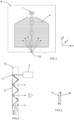
- Figure 1 is a top view of a known waveguide 6.
- Figure 2 is a side view of the same waveguide 6.
- An input diffraction grating 1 is provided on a surface of the waveguide 6 for coupling light from a projector 2 into the waveguide 6.
- Light that is coupled into the waveguide 6 travels by total internal reflection towards an output grating 4.
- the input and output gratings 1, 4 can be surface relief gratings having grooves that are parallel to one another.
- the input grating 1 is typically a blazed grating that preferentially diffracts light in the direction of the output grating 4.
- the grooves of the input grating 1 and the output element 4 extend in a direction that is parallel to the x-axis in the Cartesian reference frame of Figure 1 .
- Each diffractive optical element comprises a grating vector in the plane of its grooves.
- a grating vector has a direction that is normal to the grooves and a magnitude which is inversely related to the pitch (i.e. the separation) of the grooves.
- the direction of the grating vector (positive or negative) is determined by the polarity of the diffracted order of the light.
- Figure 3 shows the grating vectors of the input grating 11 and the output element 14 from the perspective of the optical path that couples light towards a viewer.
- the grating vectors 11, 14 are equal in magnitude but opposite in direction because the grating vector 11 for the input grating diffracts light into a +1 order and the grating vector 14 for the output grating 14 diffracts light into a -1 order (of course, viewed from a different perspective these polarities could equally be reversed). Adding the two grating vectors 11, 14 together produces a resultant vector having substantially zero magnitude. This configuration is chosen so that light outcoupled by the output element 4 experiences no chromatic or angular dispersion.
- Light captured within the waveguide 6 by total internal reflection interacts with the output grating 4 multiple times. At each interaction with the output grating 4 light is either diffracted and coupled out of the waveguide 6 towards the viewer, or else it is undiffracted in which case the light continues to propagate away from the input grating 1 in the negative y-direction.
- the proportion of light that is diffracted versus undiffracted is determined by the diffraction efficiency of the output grating 4.
- the diffraction efficiency is chosen so that light can be coupled out of the waveguide and towards a viewer along the full length of the output grating 4 in the direction of the y-axis.
- the brightness of light may reduce in the negative y-direction. This is because less and less light remains captured by total internal reflection as light progresses within the waveguide; this phenomenon is indicated schematically by the breadth of the arrows depicting optical paths in Figures 1 and 2 .
- a certain proportion of light remains undiffracted by the output grating 4, and continues to propagate in the negative y-direction under total internal reflection. This light is typically scattered by an edge 10 of the waveguide 6. Scattered light can be undesirably directed back towards the output grating 4. It has been determined that scattered light can produce background light that reduces the contrast of the augmented reality image that is coupled towards a viewer by the output grating 4.
- the output grating 4 can be replaced by more sophisticated output elements, such as those disclosed in WO 2016/020643 , for example.
- WO 2016/020643 an arrangement is disclosed where the output element expands light in two dimensions in an augmented reality display. This arrangement has been found to be very effective at simultaneously expanding light in two dimensions and coupling light out of the waveguide. It has been determined that scattering from waveguide edges can similarly reduce the contrast of an augmented reality image in more sophisticated output elements such as these.
- Figure 4 is a top view of a waveguide 106 in an embodiment of the invention.
- Figure 5 is a side view of the same waveguide 106.
- the configuration is similar to that of Figures 1 and 2 , and an input diffraction grating 101 is provided on a surface of the waveguide 106 for coupling light from a projector 102 into the waveguide 106.
- Light that is coupled into the waveguide 106 travels by total internal reflection towards an output grating 104, and the input and output gratings 101, 104 are surface relief gratings having grooves that are parallel to one another.
- the device further includes a return grating 112.
- the return grating 112 is positioned so that it receives light that is undiffracted from the output grating 104.
- the return grating 112 diffracts light so that it is directed back towards the output grating 104 in the positive y-direction. Returned light is then diffracted according to the diffraction efficiency of the output grating 104. Some of the returned light is diffracted by the output grating 104 thereby outcoupling the light towards the viewer. The remainder of the light will continue to propagate in the positive y-direction still captured within the waveguide 106 by total internal reflection; this is indicated schematically by dotted lines in Figures 4 and 5 . A small proportion of the returned light may remain undiffracted such that it scatters from a top edge of the waveguide 106. However, the amount of undiffracted light would be very small and it is believed that its effect on contrast of the augmented reality image would be minimal.
- Figure 6 is a diagram showing the grating vectors of the input grating 111, the output grating 114 and the return grating 122.
- the grating vectors are chosen so that light that is coupled out of the waveguide 106 and towards the viewer is diffracted by a number of diffraction gratings having vectors that combine to produce a resultant with zero magnitude.
- a first group of optical paths light is diffracted first by the input grating 101 so that it is coupled into the waveguide to undergo total internal reflection.
- Light in the first group of optical paths is then diffracted by the output grating 104 so that it is coupled out of the waveguide 106 and towards the viewer.
- the grating vectors 111, 114 are equal in magnitude. In this first group of optical paths the grating vectors 111, 114 are opposite in direction since the optical path involves a positive (+1) diffraction order followed by a negative (-1) diffraction order. As such, the resultant vector has substantially zero magnitude.
- light is diffracted first by the input grating 101 (in a +1 order), then by the return grating 122 (in a -1 order) and then by the output grating 104 (in a +1 order) so that it is coupled out of the waveguide 106 and towards the viewer.
- the grating vectors 111, 114 of the input grating 111 and the output grating 104 are oriented in the same direction and are equal in magnitude.
- the grating vector of the return grating 122 has twice the magnitude of the grating vector 111 of the input grating and acts in the opposite direction.
- the grating vectors combine to produce a resultant that has substantially zero magnitude.
- the return grating 112 has a grating vector 122 with the same orientation but twice the magnitude of the grating vector 111 of the input grating 101. This is achieved by providing the return grating 112 with grooves in the same orientation as those of the input grating 101, and by providing a pitch in the return grating 112 which is half of the pitch of grooves in the input grating 101.
- Figure 7 is a top view of a waveguide 206 in another embodiment of the invention.
- an input diffraction grating 201 is provided on a surface of the waveguide 206.
- the grooves of the input grating 201 are oriented parallel to the x-axis in the Cartesian reference frame of Figure 7 .
- Light from a projector (not shown) is diffracted by the input grating 201 and coupled into the waveguide 206 whereupon it undergoes total internal reflection.
- Light travels within the waveguide 206 towards an intermediate grating 216.
- the grooves of the intermediate grating 216 are oriented at +45° to the y-axis, within the x-y plane, which is in the plane of the waveguide 206.
- Light is diffracted by the intermediate grating 216 towards an output grating 204.
- Light is diffracted upon each interaction with the intermediate grating 216 as it travels within the waveguide 206 in the negative y-direction, captured within the waveguide 206 by total internal reflection.
- the diffraction efficiency of the intermediate grating 216 determines the proportion of light that is diffracted towards the output grating 204 versus the proportion of light that is undiffracted and continues to propagate in the negative y-direction.
- the diffraction efficiency is chosen to allow effective one-dimensional expansion of the light in the y-axis.
- the output grating 204 has grooves that are oriented parallel with the y-axis in the plane of the waveguide 206.
- the diffraction efficiency of the output grating 204 determines the proportion of light that is diffracted towards a viewer versus the proportion of light that is undiffracted and continues to propagate in the positive x-direction.
- the diffraction efficiency is chosen to allow effective one-dimensional expansion of the light in the x-axis. This configuration allows two dimensional expansion of light in the y-axis followed by the x-axis so that two-dimensional augmented reality images can be output towards a viewer.
- a proportion of light remains undiffracted by the output grating 204.
- the undiffracted light encounters the return grating 212 which has grooves oriented parallel to the y-axis.
- Light diffracted by the return grating 212 extends back towards the output grating 204 in the negative x-direction so that it has another opportunity to be diffracted by the output grating 204 and coupled towards a viewer.
- the return grating 212 has a high diffraction efficiency so that a high proportion of light is returned towards the output grating 204 to reduce the possible impact of scatter at the waveguide edge.
- the input, intermediate, output and return gratings 201, 216, 204, 212 are surface relief gratings.
- Figure 8 is a diagram showing the grating vectors of the input grating 211, the output grating 214, the intermediate grating 217 and the return grating 222.
- light is diffracted first by the input grating 201 so that it is coupled into the waveguide 206 to undergo total internal reflection.
- Light in the first group of optical paths is then diffracted by the intermediate grating 216 and subsequently by the output grating 204 so that it is coupled out of the waveguide 206 and towards the viewer.
- the grating vectors 211, 217, 214 can be combined in a right angled triangle so that the resultant has substantially zero magnitude. This is achieved because the pitch of the input grating 201 is equal to the pitch of the output grating 204.
- the intermediate grating 216 has a pitch equal to d.cos(45°), where d is the pitch of the input grating 201 and the output grating 204.
- a second group of optical paths light is diffracted first by the input grating 201 so that it is coupled into the waveguide to undergo total internal reflection.
- Light is then diffracted by the intermediate grating 216 towards the output grating 204.
- Light is undiffracted by the output grating 204 and it encounters the return grating 212 which diffracts the light back towards the output grating 204 so that it can be coupled out of the waveguide 206 towards a viewer.
- Light in the second group of optical paths is therefore diffracted by four gratings before it is coupled towards a viewer.
- the grating vectors for these gratings 211, 217, 214, 222 can be combined to produce a resultant vector having substantially zero magnitude.
- the return grating 212 has grooves that are parallel to those in the output grating 204, but the pitch of the grooves in the return grating 212 is half that of the output grating 204; thus, the grating vector 222 for the return grating has twice the magnitude of the output grating vector 214.
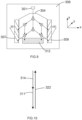
- Figure 9 is a top view of a waveguide 306 in another embodiment of the invention.
- an input diffraction grating 301 is provided on a surface of the waveguide 306.
- the grooves of the input grating 301 are oriented parallel to the x-axis in the Cartesian reference frame of Figure 9 .
- Light from a projector (not shown) is diffracted by the input grating 301 and coupled into the waveguide 306 whereupon it undergoes total internal reflection.
- Light travels within the waveguide 306 towards an output element 304.
- the output element 304 is a pair of crossed gratings or a photonic crystal as described in WO 2016/020643 .
- the output element 304 comprises first and second diffractive optical elements overlaid on one another in or on the waveguide 306.
- the first diffractive optical element is arranged with rows of diffractive optical structures oriented at an angle of -30° to the y-axis.
- the second diffractive optical element is arranged with rows of diffractive optical structures oriented at an angle of +30° to the y-axis, within the x-y plane.
- the first diffractive optical element is configured to receive light from the input grating 301 and to diffract it into an order that extends in a direction angled at +120° to the y-axis.
- the second output diffractive optical element which is orthogonal to the diffracted order extending at +120° to the y-axis so that it can provide outcoupled orders towards a viewer.
- the second output diffractive optical element is configured to receive light from the input grating 301 and diffract it into an order that extends in a direction angled at -120° to the y-axis.
- These diffracted orders can then be diffracted by the first output diffractive optical element which is orthogonal to the diffracted orders and can provide outcoupled orders towards a viewer.
- the diffraction efficiencies of the first and second output diffractive optical elements within the output element 304 are chosen to allow the light to simultaneously expand in two-dimensions while providing outcoupled orders towards a viewer as augmented reality images.
- the device shown in Figure 9 also includes first, second and third return gratings 307, 309, 312.
- the first return grating 307 has grooves oriented at -30° to the y-axis.
- the second return grating 309 has grooves oriented at +30° to the y-axis.
- the third return grating 312 has grooves oriented parallel to the x-axis.
- Each return grating 307, 309, 312 can receive light which has not been coupled towards a viewer by the output element 304 and return the light towards the output element 304.
- the output element 304 There is a very large number of possible optical paths within the output element 304, but this can be simplified by considering four options for light upon its first interaction with the output element 304, following diffraction by the input grating 301.
- the light may be undiffracted such that it continues to propagate in the negative y-direction, still captured within the waveguide 306 by total internal reflection.
- the light may be diffracted by the first diffractive optical element with grooves angled at -30° to the y-axis so that light extends in a direction at +120° to the y-axis.
- the light may be diffracted by the second diffractive optical element with grooves angled at +30° to the y-axis so that light extends in a direction at -120° to the y-axis.
- light may be diffracted by a superposition of the first and second diffractive optical elements which has effective grooves that are parallel to the x-axis so that light is coupled directly out of the waveguide 306 towards a viewer; this is sometimes referred to as the straight-to-eye (STE) order.
- STE straight-to-eye
- the superposition of the first and second diffractive optical elements may be considered as a third diffractive optical element having a grating vector that is angled resepectively at 60° to the first and second diffractive optical elements; thus, the grating vectors for the first, second and third diffractive optical elements within the output element 304 may be combined in an equilateral triangle.
- a first optical path light in the waveguide 306 light is diffracted by the input grating 301 and coupled into the waveguide 306 whereupon it undergoes total internal reflection extending in the negative y-direction towards the output element 304.
- this first optical path light is undiffracted by the output element 304 and it continues to propagate in the negative y-direction until it encounters the third return grating 312.
- Light is diffracted by the third return grating 312 so that it returns towards the output element 304 in the positive y-direction.
- Light then has another opportunity to be diffracted by the output element 304 so that it can be coupled out of the waveguide 306 and towards a viewer.
- the returned light is diffracted by the superposition of the first and second diffractive optical elements having a grating vector that is parallel to the y-axis; in other words, the returned light is a STE order upon interaction with the output element 304, following diffraction by the third return grating 312.
- Figure 10 is a schematic diagram showing the grating vectors of the input grating 311, the third return grating 322 and the output element 322, where the grating vector of the output element 322 is a superposition of the grating vectors of the first and second diffractive optical elements which are angled at ⁇ 30° to the y-axis and are overlaid on top of one another in the waveguide; the equal and opposite components aligned with the x-axis cancel one another, leaving a resultant vector that is aligned with the y-axis.
- Light in the first optical path is therefore diffracted by three diffractive optical elements before it is coupled towards a viewer.
- the input grating 301 diffracts light into a +1 order
- the return grating 312 diffracts light into a -1 order
- the output element 304 diffracts light into a +1 order.
- the grating vectors 311, 322, 314 can therefore be added together as shown in Figure 10 to produce a resultant vector having substantially zero magnitude. This is achieved because the return grating 312 has a pitch that is half that of the input grating 301 and the superposition of the first and second output diffractive optical elements in the output element 304.
- a second exemplary optical path in the waveguide 306 light is diffracted by the input grating 301 and subsequently light is diffracted by the first diffractive optical element with grooves angled at -30° to the y-axis.
- the diffracted light extends in a direction that is oriented at +120° to the y-axis (i.e. in a direction that is towards the second return grating 309).
- Light continues to propagate towards the second return grating 309 and at each interaction with the output element 304 light is either diffracted by the second diffractive optical element having grooves oriented at +30° to the y-axis so that it can be coupled out of the waveguide 306 towards a viewer or else it is undiffracted and continues to propagate towards the second return grating 309, in a direction that is oriented at 120° to the y-axis.
- Some light remains undiffracted by the second diffractive optical element in which case it encounters the second return grating 309.
- the second return grating 309 diffracts the light so that it is returned towards the output element 304 in the opposite direction (i.e.
- the returned light has another opportunity to interact with the second diffractive optical element with grooves oriented at +30°.
- light is diffracted by the second diffractive optical element it is coupled out of the waveguide 306 towards a viewer in a direction that is parallel to the z-axis.
- Figure 11 is a schematic diagram showing grating vectors for the active diffractive interactions along this second exemplary optical path.
- light is diffracted sequentially by the input grating 301, the first diffractive optical element with grooves angled at -30° to the y-axis, the second return grating 309 and finally by the second diffractive optical element with grooves angled at +30° to the y-axis.
- the respective grating vectors 311, 323, 325, 327 can be added together to produce a resultant vector having zero magnitude.
- the grating vector 311 for the input grating is oriented at 60° to the grating vector 323 for the first diffractive optical element, and these grating vectors 311, 323 have the same magnitude.
- the grating vector 325 for the second return grating is angled at 60° to the grating vector 323 for the first diffractive optical element, but has twice the magnitude.
- the grating vector 327 for the second diffractive optical element is oriented in the same direction as the grating vector 325 for the second return grating, but has half the magnitude.
- a third exemplary optical path is also discussed, which is a mirror image of the second exemplary optical path.
- this third optical path in the waveguide 306 light is diffracted by the input grating 301 and subsequently light is diffracted by the second diffractive optical element with grooves angled at +30° to the y-axis.
- the diffracted light extends in a direction that is oriented at -120° to the y-axis (i.e. in a direction that is towards the first return grating 307).
- Light continues to propagate towards the first return grating 307 and at each interaction with the output element 304 light is either diffracted by the first diffractive optical element having grooves oriented at -30° to the y-axis so that it can be coupled out of the waveguide 306 towards a viewer or else it is undiffracted and continues to propagate towards the first return grating 307, in a direction that is oriented at -120° to the y-axis. Some light remains undiffracted by the first diffractive optical element in which case it encounters the first return grating 307.
- the first return grating 307 diffracts the light so that it is returned towards the output element 304 in the opposite direction (i.e.
- the returned light has another opportunity to interact with the first diffractive optical element with grooves oriented at -30° to the y-axis.
- first diffractive optical element When light is diffracted by the first diffractive optical element it is coupled out of the waveguide 306 towards a viewer in a direction that is parallel to the z-axis.
- Figure 12 is a schematic diagram showing grating vectors for the active diffractive interactions along this third exemplary optical path.
- light is diffracted sequentially by the input grating 301, the second diffractive optical element with grooves angled at +30° to the y-axis, the first return grating 307 and finally by the first diffractive optical element with grooves angled at -30° to the y-axis.
- the respective grating vectors 311, 327, 329, 323 can be added together to produce a resultant vector having zero magnitude.
- the grating vector 311 for the input grating is oriented at 60° to the grating vector 327 for the second diffractive optical element, and these grating vectors 311, 327 have the same magnitude.
- the grating vector 329 for the first return grating is angled at 60° to the grating vector 327 for the first diffractive optical element, but has twice the magnitude.
- the grating vector 323 for the first diffractive optical element is oriented in the same direction as the grating vector 329 for the first return grating, but has half the magnitude.
- the first, second and third return gratings 307, 309, 312 can return light towards the output element 304. This can reduce scatter from waveguide edges, thereby improving the contrast of augmented reality images that are coupled out of the waveguide 306 and towards the viewer along the z-axis.
- FIG 13 is a top view of a waveguide 406 in another embodiment of the invention, which is structurally similar to the waveguide 306 described above and shown in Figure 9 .
- the third return grating includes a first portion 412a and a second portion 412b.
- the first portion 412a of the third return grating has grooves oriented at -60° to the y-axis.
- the second portion 412b of the third return grating has grooves oriented at +60° to the y-axis.
- Each return grating 407, 409, 412a, 412b can receive light which has not been coupled towards a viewer by the output element 404 and return the light towards the output element 404.
- a first exemplary optical path in the waveguide 406 light is diffracted by the input grating 401 and coupled into the waveguide 406 whereupon it undergoes total internal reflection extending in the negative y-direction towards the output element 404.
- this first optical path light is initially undiffracted by the output element 304 and it continues to propagate in the negative y-direction.
- light is then diffracted by the second diffractive optical element within the output element 304, having grooves angled at +30° to the y-axis.
- the diffracted light extends in a direction that is oriented at -120° to the y-axis (i.e. downwards and leftwards in the top view of Figure 13 ).
- Light continues to propagate in this direction until it encounters the first portion 412a of the third return grating.
- light is diffracted in the output element 404 at a position with respect to the y-axis which means that it encounters the first portion 412a of the third return grating, rather than the first return grating 407.
- Light is diffracted by the first portion 412a of the third return grating so that it returns towards the output element 404 in the positive y-direction (i.e. parallel to the y-axis).
- the returned light is diffracted by the superposition of the first and second diffractive optical elements having a grating vector that is parallel to the y-axis; in other words, the returned light is a STE order upon interaction with the output element 404, following diffraction by the first portion 412a of the third return grating 412.
- Figure 14 is a schematic diagram showing grating vectors for the active diffractive interactions along this first exemplary optical path.
- light is diffracted sequentially by the input grating 401, the second diffractive optical element with grooves angled at +30° to the y-axis, the first portion 412a of the third return grating, with grooves angled at -60° to the y-axis, and finally by a superposition of the grating vectors of the first and second diffractive optical elements which has a grating vector that is aligned with the y-axis (i.e. effective grooves which are parallel to the x-axis).
- grating vectors 411, 423, 440, 414 These four sequential diffractive interactions are depicted by grating vectors 411, 423, 440, 414.
- the input grating 401 has grooves oriented parallel to the x-axis and with a groove separation 'd'.
- grating vector 411 (for the input grating 401) is parallel to the y-axis.
- the second diffractive optical element with grooves angled at +30° to the y-axis also has a groove separation 'd'.
- the first portion 412a of the third return grating has grooves angled at -60° to the y-axis and a groove separation which is d/(2*cos(30°)).
- the grating vector 414 corresponding to the superposition of the grating vectors of the first and second diffractive optical elements has an effective groove separation which is 'd'.
- these grating vectors 411, 423, 440, 414 are combined they produce a resultant vector which has substantially zero magnitude, which means that this sequence of diffractive interactions can provide outcoupled orders towards a viewer with minimum angular and chromatic aberrations.
- a second exemplary optical path can be considered, which is effectively a mirror image of the first exemplary optical path described above, about the y-axis.
- 406 light is diffracted sequentially by the input grating 401, the first diffractive optical element within the output element 304, having grooves angled at -30° to the y-axis, the second portion 412b of the third return grating, and finally by the superposition of the first and second diffractive optical elements having a grating vector that is parallel to the y-axis.
- These four sequential diffractive interactions are depicted in Figure 16 with grating vectors 411, 427, 442, 414.
- the input grating 401 has grooves oriented parallel to the x-axis and a groove separation 'd'.
- grating vector 411 (for the input grating 401) is parallel to the y-axis.
- the first diffractive optical element has grooves angled at -30° to the y-axis and also has a groove separation 'd'.
- the second portion 412b of the third return grating has grooves angled at +60° to the y-axis and a groove separation which is d/(2*cos(30°)).
- the grating vector 414 corresponding to the superposition of the grating vectors of the first and second diffractive optical elements has an effective groove separation which is 'd'.
- a third exemplary optical path in the waveguide 406 light is diffracted by the input grating 401 and coupled into the waveguide 406 whereupon it undergoes total internal reflection extending in the negative y-direction towards the output element 404.
- this third optical path light is undiffracted by the output element 304 and it continues to propagate in the negative y-direction towards the third return grating whereupon it is diffracted by the first portion 412a of the third return grating.
- the diffracted light extends back towards the output element 404 whereupon it is diffracted by the first diffractive optical element within the output element 404, having grooves angled at +30° to the y-axis, and coupled out of the waveguide 406 towards a viewer in a direction that is parallel with the z-axis.
- These three sequential diffractive interactions are depicted in Figure 15 with grating vectors 411, 440, 427 which are added together to produce a resultant vector with substantially zero magnitude.
- a fourth exemplary optical path is effectively a mirror opposite of the third exemplary optical path, about the y-axis.
- light is diffracted by the input grating 401 and coupled into the waveguide 406 whereupon it undergoes total internal reflection extending in the negative y-direction towards the output element 404.
- Light is undiffracted by the output element 304 and it continues to propagate in the negative y-direction towards the third return grating whereupon it is diffracted by the second portion 412b of the third return grating.
- the diffracted light extends back towards the output element 404 whereupon it is diffracted by the second diffractive optical element within the output element 404, having grooves angled at -30° to the y-axis, and coupled out of the waveguide 406 towards a viewer in a direction that is parallel with the z-axis.
- These three sequential diffractive interactions are depicted in Figure 17 with grating vectors 411, 442, 423 which are added together to produce a resultant vector with substantially zero magnitude.
- first and second portions 412a, 412b of the third return grating in Figure 13 allow light to be returned to the output element both when rays are received undiffracted from the output element 404 and when a single turning diffractive interaction has taken place.
- Figure 18 is a top view of another waveguide 506 in an embodiment of the invention, which is structurally similar to the waveguide 306 described above and shown in Figure 9 .
- the first return grating 507 situated to the left of the output element 504, has grooves oriented parallel to the y-axis.
- the second return grating 509 situated to the right of the output element 504 also has grooves oriented parallel to the y-axis.
- no third return grating is shown, although it would be possible to include a third return grating in a similar way to that shown in Figures 9 or 13 .
- a first exemplary optical path in the waveguide 506 light is diffracted by the input grating 501 and coupled into the waveguide 506 whereupon it undergoes total internal reflection extending in the negative y-direction towards the output element 504.
- this first optical path light is diffracted by the second diffractive optical element within the output element 504, having grooves angled at +30° to the y-axis.
- the diffracted light extends in a direction that is oriented at -120° to the y-axis (i.e. downwards and leftwards in the top view of Figure 18 ) until it encounters the first return grating 507, whereupon light is diffracted back towards the output element 504.
- FIG. 19 is a schematic diagram showing grating vectors for the active diffractive interactions along this first exemplary optical path.
- grating vectors 511, 523, 515, 523 The input grating 401 has grooves oriented parallel to the x-axis and with a separation 'd'.
- grating vector 411 for the input grating 401 is parallel to the y-axis.
- the second diffractive optical element with grooves angled at +30° to the y-axis also has a groove separation 'd'.
- the first return grating 507 has grooves angled parallel to the y-axis and a groove separation which is d/(2*sin(60°)).
- the second diffractive optical element with grooves angled at +30° to the y-axis also has a groove separation 'd'.
- a second exemplary optical path is effectively a mirror image of the first optical path described above, about the y-axis.
- light is diffracted by the input grating 501 and coupled into the waveguide 506 whereupon it undergoes total internal reflection extending in the negative y-direction towards the output element 504.
- Light is then diffracted by the first diffractive optical element within the output element 504, having grooves angled at -30° to the y-axis.
- the diffracted light extends in a direction that is oriented at +120° to the y-axis (i.e. downwards and rightwards in the top view of Figure 18 ) until it encounters the second return grating 509, whereupon light is diffracted back towards the output element 504.
- FIG. 20 is a schematic diagram showing grating vectors for the active diffractive interactions along this second exemplary optical path.
Landscapes
- Physics & Mathematics (AREA)
- General Physics & Mathematics (AREA)
- Optics & Photonics (AREA)
- Chemical & Material Sciences (AREA)
- Crystallography & Structural Chemistry (AREA)
- Optical Couplings Of Light Guides (AREA)
Description
- The present invention relates to a display for augmented reality applications.
- In an augmented reality headset a transparent waveguide is provided in front of a user's eye or eyes. A light projector transmits light towards the waveguide. Light can be coupled into the waveguide by an input diffraction grating. Light then propagates within the waveguide by total internal reflection and an output diffraction grating couples light out of the waveguide and towards a viewer. In use, a viewer can see light from their external environment, transmitted through the transparent waveguide, as well as projected light from the projector. This can provide an augmented reality experience. A virtual reality headset works in a similar way, except that the user can only see projected light, and cannot see any light from their external environment.
- One challenge in the field of augmented reality devices is to improve the contrast of the image that is output to the viewer. An object of the present invention is to address this issue.
- In
US 2018/324402 A1 , a resonating optical waveguide that increases image intensity and uniformity is provided. - In
US 2019/004321 A1 , an optical device is disclosed for expanding input light in two dimensions in an augmented reality display. - According to an aspect of the invention there is provided an augmented reality device, comprising: a waveguide; an input diffractive optical element positioned in or on the waveguide configured to receive light from a projector and to couple the light into the waveguide so that it is captured within the waveguide by total internal reflection; an output diffractive optical element positioned in or on the waveguide configured to couple totally internally reflected light out of the waveguide towards a viewer; and a returning diffractive optical element positioned in or on the waveguide configured to receive light from the output diffractive optical element and to diffract the received light so that it is returned towards the output diffractive optical element.
- In this way, the returning diffractive optical element can reduce scatter at the edge of the waveguide by returning light to the output diffractive optical element. This allows unused light at the edge of the waveguide to be recycled back towards the output diffractive optical element where it can be coupled towards a viewer. Advantageously this improves the contrast of the augmented reality device by reducing stray light in the output region. Additionally, this improves optical efficiency in the device because more of the light from the projector can be coupled towards the viewer, rather than being wasted in scattered rays.
- Light is preferably received at the returning diffractive optical element from the direction of the output diffractive optical element, although the light is preferably undiffracted by the output diffractive optical element in the sense that the light received at the returning diffractive optical element is light that is not coupled out of the waveguide by the output diffractive optical element. In some embodiments there may be some diffractive interaction with light in the output diffractive optical element before it is received at the returning diffractive optical element, but such diffractive interaction preferably only turns light within the waveguide rather than coupling it out of the waveguide and towards a viewer.
- Preferably rays of light that are coupled out of the waveguide towards a viewer undergo diffraction by a plurality of diffractive optical elements having grating vectors that combine to produce a resultant vector with substantially zero magnitude. In this way, light can be coupled out of the waveguide with substantially no angular and chromatic dispersion.
- Of course, there may be a very large number of possible optical paths by which light can be coupled from a projector towards a viewer. In general terms, we can consider at least two groups of optical paths. In the first group of optical paths, light may be diffracted by the input diffractive optical element, coupled into the waveguide whereupon it undergoes total internal reflection, and then coupled out of the waveguide by the output diffractive optical element without interacting with the returning diffractive optical element. In the second group of optical paths, light may be diffracted by the input diffractive optical element, and coupled into the waveguide whereupon it undergoes total internal reflection. In the second group, the light is then diffracted by the returning diffractive optical element before being coupled out of the waveguide by the output diffractive optical element. In both the first and second group of optical paths, the grating vectors of the diffractive optical elements that diffract the light preferably combine to produce a resultant with substantially zero magnitude.
- The resultant vector of the grating vectors for the input diffractive optical element and the output diffractive optical element may combine to produce a resultant vector with substantially zero magnitude. This can allow some optical paths to be output with no angular or chromatic aberration.
- The resultant vector of the grating vectors for the input diffractive optical element, the returning diffractive optical element and the output diffractive optical element may combine to produce a resultant vector with substantially zero magnitude. In this way, light can be coupled out of the waveguide with substantially no angular and chromatic dispersion for another group of optical paths.
- In some embodiments there may be an intermediate diffractive optical element positioned in or on the waveguide between the input diffractive optical element and the output diffractive optical element (i.e. from the perspective of the optical path). The intermediate diffractive optical element may be oriented at an angle that allows light to be expanded in a first dimension before it encounters the output diffractive optical element. The output diffractive optical element can then expand light in a second dimension, which may be perpendicular to the first dimension.
- Preferably the grating vectors for the input diffractive optical element, the intermediate diffractive optical element and the output diffractive optical element combine to produce a resultant vector with substantially zero magnitude. Preferably the grating vectors for the input diffractive optical element, the intermediate diffractive optical element, the returning diffractive optical element and the output diffractive optical element combine to produce a resultant vector with substantially zero magnitude.
- The output diffractive optical element comprises first and second output diffractive optical elements overlaid on one another in or on the waveguide. The first output diffractive optical element is configured to receive light from an input direction and couple it towards the second output diffractive optical element which can then provide outcoupled orders towards a viewer. The second output diffractive optical element is configured to receive light from an input direction and couple it towards the first output diffractive optical element which can then provide outcoupled orders towards a viewer. The output diffractive optical element comprises a plurality of optical structures in a photonic crystal, and the plurality of optical structures are arranged in an array to provide the first and second output diffractive optical elements. First and second returning diffractive optical elements are also provided. The first returning diffractive optical element is positioned to receive light from the first output diffractive optical element and to diffract the received light so that it is returned towards the output diffractive optical element when can then provide outcoupled orders towards a viewer. The second returning diffractive optical element is positioned to receive light from the second output diffractive optical element and to diffract the received light so that it is returned towards the output diffractive optical element when can then provide outcoupled orders towards a viewer. The first returning diffractive optical element may have grooves which are aligned with the grooves of the first diffractive optical element (and, correspondingly, grating vectors which are aligned). The second returning diffractive optical element may have grooves which are aligned with the grooves of the second diffractive optical element. In another configuration, the first and second returning diffractive optical elements may have grooves which are perpendicular to the grooves of the input diffractive optical element. The pitches of the grooves in the first and second returning diffractive optical elements are preferably selected so that the grating vectors of the various diffractive optical elements that combine to produce an outcoupled order to the viewer can be combined additively to produce a resultant vector with substantially zero magnitude.
- The device may further comprise a third returning diffractive optical element positioned to receive light from the first and second output diffractive optical elements and to diffract the received light so that it is returned towards the first and second output diffractive optical elements. In this way, the returning diffractive optical elements can effectively recycle light extending towards the edges of the waveguide within a photonic crystal structure. This can facilitate use of a photonic crystal that simultaneously expands light in two dimensions while improving contrast within the output diffractive optical element.
- In one embodiment the third returning diffractive optical element may have grooves in the same orientation as the grooves in the input diffractive optical element. In another embodiment the third returning diffractive optical element may have first and second portions with grooves in different orientations. Specifically, the first and second portions may have grooves that are oriented at ±60° to the y-axis, which is the direction in which the input diffractive optical element couples light towards the output diffractive optical element in the waveguide. This configuration can effectively return light towards the output diffractive optical element, thereby reducing scatter from waveguide edges, whether the light is undiffracted within the output diffractive optical element, or whether a single turning diffraction has occurred such that the light has been re-directed within the output diffractive optical element but is still captured within the waveguide by total internal reflection. This may return light towards the output diffractive optical element for a higher number of optical paths, thereby minimising scatter from waveguide edges and improving contrast for the augmented reality image.
- Embodiments of the invention are now described, by way of example, with reference to the drawings, in which:
-
Figure 1 is a top view of a known waveguide; -
Figure 2 is a side view of the waveguide shown inFigure 1 ; -
Figure 3 is a schematic diagram showing grating vectors for diffractive optical elements in the waveguide shown inFigure 1 ; -
Figure 4 is a top view of a waveguide in an embodiment of the present invention; -
Figure 5 is a side view of the waveguide shown inFigure 4 ; -
Figure 6 is a schematic diagram showing grating vectors for diffractive optical elements in the waveguide shown inFigure 4 ; -
Figure 7 is a top view of a waveguide in another embodiment of the present invention; -
Figure 8 is a schematic diagram showing grating vectors for diffractive optical elements in the waveguide shown inFigure 7 ; -
Figure 9 is a top view of a waveguide in another embodiment of the present invention; -
Figure 10 is a schematic diagram showing grating vectors for one combination of diffractive optical elements in the waveguide shown inFigure 9 ; -
Figure 11 is a schematic diagram showing grating vectors for another combination of diffractive optical elements in the waveguide shown inFigure 9 ; -
Figure 12 is a schematic diagram showing grating vectors for another combination of diffractive optical elements in the waveguide shown inFigure 9 ; -
Figure 13 is a top view of a waveguide in another embodiment of the present invention; -
Figure 14 is a schematic diagram showing grating vectors for one combination of diffractive optical elements in the waveguide shown inFigure 13 ; -
Figure 15 is a schematic diagram showing grating vectors for another combination of diffractive optical elements in the waveguide shown inFigure 13 ; -
Figure 16 is a schematic diagram showing grating vectors for another combination of diffractive optical elements in the waveguide shown inFigure 13 ; -
Figure 17 is a schematic diagram showing grating vectors for another combination of diffractive optical elements in the waveguide shown inFigure 13 ; -
Figure 18 is a top view of a waveguide in another embodiment of the present invention; -
Figure 19 is a schematic diagram showing grating vectors for one combination of diffractive optical elements in the waveguide shown inFigure 18 ; and -
Figure 20 is a schematic diagram showing grating vectors for another combination of diffractive optical elements in the waveguide shown inFigure 18 . -
Figure 1 is a top view of a knownwaveguide 6.Figure 2 is a side view of thesame waveguide 6. Aninput diffraction grating 1 is provided on a surface of thewaveguide 6 for coupling light from aprojector 2 into thewaveguide 6. Light that is coupled into thewaveguide 6 travels by total internal reflection towards anoutput grating 4. In this arrangement the input andoutput gratings output grating 4. In this arrangement the grooves of the input grating 1 and theoutput element 4 extend in a direction that is parallel to the x-axis in the Cartesian reference frame ofFigure 1 . - Each diffractive optical element comprises a grating vector in the plane of its grooves. A grating vector has a direction that is normal to the grooves and a magnitude which is inversely related to the pitch (i.e. the separation) of the grooves. The direction of the grating vector (positive or negative) is determined by the polarity of the diffracted order of the light.
Figure 3 shows the grating vectors of the input grating 11 and theoutput element 14 from the perspective of the optical path that couples light towards a viewer. Along the optical path thegrating vectors 11, 14 are equal in magnitude but opposite in direction because the grating vector 11 for the input grating diffracts light into a +1 order and thegrating vector 14 for the output grating 14 diffracts light into a -1 order (of course, viewed from a different perspective these polarities could equally be reversed). Adding the twograting vectors 11, 14 together produces a resultant vector having substantially zero magnitude. This configuration is chosen so that light outcoupled by theoutput element 4 experiences no chromatic or angular dispersion. - Light captured within the
waveguide 6 by total internal reflection interacts with the output grating 4 multiple times. At each interaction with the output grating 4 light is either diffracted and coupled out of thewaveguide 6 towards the viewer, or else it is undiffracted in which case the light continues to propagate away from the input grating 1 in the negative y-direction. The proportion of light that is diffracted versus undiffracted is determined by the diffraction efficiency of theoutput grating 4. The diffraction efficiency is chosen so that light can be coupled out of the waveguide and towards a viewer along the full length of the output grating 4 in the direction of the y-axis. If the diffraction efficiency of theoutput grating 4 is constant along the y-axis then the brightness of light may reduce in the negative y-direction. This is because less and less light remains captured by total internal reflection as light progresses within the waveguide; this phenomenon is indicated schematically by the breadth of the arrows depicting optical paths inFigures 1 and 2 . - A certain proportion of light remains undiffracted by the
output grating 4, and continues to propagate in the negative y-direction under total internal reflection. This light is typically scattered by anedge 10 of thewaveguide 6. Scattered light can be undesirably directed back towards theoutput grating 4. It has been determined that scattered light can produce background light that reduces the contrast of the augmented reality image that is coupled towards a viewer by theoutput grating 4. - In other known arrangements the output grating 4 can be replaced by more sophisticated output elements, such as those disclosed in
WO 2016/020643 , for example. InWO 2016/020643 an arrangement is disclosed where the output element expands light in two dimensions in an augmented reality display. This arrangement has been found to be very effective at simultaneously expanding light in two dimensions and coupling light out of the waveguide. It has been determined that scattering from waveguide edges can similarly reduce the contrast of an augmented reality image in more sophisticated output elements such as these. - For simplicity the arrangement in
Figures 1 to 3 has been described in the context of a single projector and a single waveguide. However, the skilled person will appreciate that multiple waveguides and projectors can be used in different configurations. It is common, for example, to use a stack of three waveguides each of which is optimised for a different primary colour in order to produce a full colour augmented reality image. The same issues can arise in multiple waveguide stacks regarding back scatter from waveguide edges. -
Figure 4 is a top view of awaveguide 106 in an embodiment of the invention.Figure 5 is a side view of thesame waveguide 106. The configuration is similar to that ofFigures 1 and 2 , and aninput diffraction grating 101 is provided on a surface of thewaveguide 106 for coupling light from aprojector 102 into thewaveguide 106. Light that is coupled into thewaveguide 106 travels by total internal reflection towards anoutput grating 104, and the input andoutput gratings - In this configuration the device further includes a return grating 112. The return grating 112 is positioned so that it receives light that is undiffracted from the
output grating 104. The return grating 112 diffracts light so that it is directed back towards the output grating 104 in the positive y-direction. Returned light is then diffracted according to the diffraction efficiency of theoutput grating 104. Some of the returned light is diffracted by the output grating 104 thereby outcoupling the light towards the viewer. The remainder of the light will continue to propagate in the positive y-direction still captured within thewaveguide 106 by total internal reflection; this is indicated schematically by dotted lines inFigures 4 and 5 . A small proportion of the returned light may remain undiffracted such that it scatters from a top edge of thewaveguide 106. However, the amount of undiffracted light would be very small and it is believed that its effect on contrast of the augmented reality image would be minimal. -
Figure 6 is a diagram showing the grating vectors of the input grating 111, the output grating 114 and the return grating 122. The grating vectors are chosen so that light that is coupled out of thewaveguide 106 and towards the viewer is diffracted by a number of diffraction gratings having vectors that combine to produce a resultant with zero magnitude. In a first group of optical paths light is diffracted first by the input grating 101 so that it is coupled into the waveguide to undergo total internal reflection. Light in the first group of optical paths is then diffracted by the output grating 104 so that it is coupled out of thewaveguide 106 and towards the viewer. - The
grating vectors grating vectors waveguide 106 and towards the viewer. In this situation thegrating vectors grating vector 111 of the input grating and acts in the opposite direction. Thus, the grating vectors combine to produce a resultant that has substantially zero magnitude. - The return grating 112 has a
grating vector 122 with the same orientation but twice the magnitude of thegrating vector 111 of the input grating 101. This is achieved by providing the return grating 112 with grooves in the same orientation as those of the input grating 101, and by providing a pitch in the return grating 112 which is half of the pitch of grooves in the input grating 101. -
Figure 7 is a top view of awaveguide 206 in another embodiment of the invention. In this arrangement aninput diffraction grating 201 is provided on a surface of thewaveguide 206. The grooves of the input grating 201 are oriented parallel to the x-axis in the Cartesian reference frame ofFigure 7 . Light from a projector (not shown) is diffracted by the input grating 201 and coupled into thewaveguide 206 whereupon it undergoes total internal reflection. Light travels within thewaveguide 206 towards anintermediate grating 216. The grooves of theintermediate grating 216 are oriented at +45° to the y-axis, within the x-y plane, which is in the plane of thewaveguide 206. Light is diffracted by theintermediate grating 216 towards anoutput grating 204. Light is diffracted upon each interaction with theintermediate grating 216 as it travels within thewaveguide 206 in the negative y-direction, captured within thewaveguide 206 by total internal reflection. The diffraction efficiency of theintermediate grating 216 determines the proportion of light that is diffracted towards the output grating 204 versus the proportion of light that is undiffracted and continues to propagate in the negative y-direction. The diffraction efficiency is chosen to allow effective one-dimensional expansion of the light in the y-axis. Light that is diffracted by theintermediate diffraction grating 216 travels in the positive x-direction, still captured within thewaveguide 206 by total internal reflection. Light then interacts with theoutput grating 204. Theoutput grating 204 has grooves that are oriented parallel with the y-axis in the plane of thewaveguide 206. The diffraction efficiency of the output grating 204 determines the proportion of light that is diffracted towards a viewer versus the proportion of light that is undiffracted and continues to propagate in the positive x-direction. The diffraction efficiency is chosen to allow effective one-dimensional expansion of the light in the x-axis. This configuration allows two dimensional expansion of light in the y-axis followed by the x-axis so that two-dimensional augmented reality images can be output towards a viewer. - A proportion of light remains undiffracted by the
output grating 204. The undiffracted light encounters the return grating 212 which has grooves oriented parallel to the y-axis. Light diffracted by the return grating 212 extends back towards the output grating 204 in the negative x-direction so that it has another opportunity to be diffracted by the output grating 204 and coupled towards a viewer. The return grating 212 has a high diffraction efficiency so that a high proportion of light is returned towards the output grating 204 to reduce the possible impact of scatter at the waveguide edge. - The input, intermediate, output and return
gratings Figure 8 is a diagram showing the grating vectors of the input grating 211, the output grating 214, theintermediate grating 217 and the return grating 222. In a first group of optical paths light is diffracted first by the input grating 201 so that it is coupled into thewaveguide 206 to undergo total internal reflection. Light in the first group of optical paths is then diffracted by theintermediate grating 216 and subsequently by the output grating 204 so that it is coupled out of thewaveguide 206 and towards the viewer. Thegrating vectors output grating 204. Theintermediate grating 216 has a pitch equal to d.cos(45°), where d is the pitch of the input grating 201 and theoutput grating 204. - In a second group of optical paths light is diffracted first by the input grating 201 so that it is coupled into the waveguide to undergo total internal reflection. Light is then diffracted by the
intermediate grating 216 towards theoutput grating 204. Light is undiffracted by the output grating 204 and it encounters the return grating 212 which diffracts the light back towards the output grating 204 so that it can be coupled out of thewaveguide 206 towards a viewer. Light in the second group of optical paths is therefore diffracted by four gratings before it is coupled towards a viewer. The grating vectors for thesegratings grating vector 222 for the return grating has twice the magnitude of theoutput grating vector 214. -
Figure 9 is a top view of awaveguide 306 in another embodiment of the invention. In this arrangement aninput diffraction grating 301 is provided on a surface of thewaveguide 306. The grooves of the input grating 301 are oriented parallel to the x-axis in the Cartesian reference frame ofFigure 9 . Light from a projector (not shown) is diffracted by the input grating 301 and coupled into thewaveguide 306 whereupon it undergoes total internal reflection. Light travels within thewaveguide 306 towards anoutput element 304. In this arrangement theoutput element 304 is a pair of crossed gratings or a photonic crystal as described inWO 2016/020643 . Thus, theoutput element 304 comprises first and second diffractive optical elements overlaid on one another in or on thewaveguide 306. The first diffractive optical element is arranged with rows of diffractive optical structures oriented at an angle of -30° to the y-axis. The second diffractive optical element is arranged with rows of diffractive optical structures oriented at an angle of +30° to the y-axis, within the x-y plane. The first diffractive optical element is configured to receive light from the input grating 301 and to diffract it into an order that extends in a direction angled at +120° to the y-axis. These orders can then be diffracted by the second output diffractive optical element which is orthogonal to the diffracted order extending at +120° to the y-axis so that it can provide outcoupled orders towards a viewer. Similarly, the second output diffractive optical element is configured to receive light from the input grating 301 and diffract it into an order that extends in a direction angled at -120° to the y-axis. These diffracted orders can then be diffracted by the first output diffractive optical element which is orthogonal to the diffracted orders and can provide outcoupled orders towards a viewer. The diffraction efficiencies of the first and second output diffractive optical elements within theoutput element 304 are chosen to allow the light to simultaneously expand in two-dimensions while providing outcoupled orders towards a viewer as augmented reality images. - The device shown in
Figure 9 also includes first, second andthird return gratings output element 304 and return the light towards theoutput element 304. - There is a very large number of possible optical paths within the
output element 304, but this can be simplified by considering four options for light upon its first interaction with theoutput element 304, following diffraction by the input grating 301. First, the light may be undiffracted such that it continues to propagate in the negative y-direction, still captured within thewaveguide 306 by total internal reflection. Second, the light may be diffracted by the first diffractive optical element with grooves angled at -30° to the y-axis so that light extends in a direction at +120° to the y-axis. Third, the light may be diffracted by the second diffractive optical element with grooves angled at +30° to the y-axis so that light extends in a direction at -120° to the y-axis. Fourth, light may be diffracted by a superposition of the first and second diffractive optical elements which has effective grooves that are parallel to the x-axis so that light is coupled directly out of thewaveguide 306 towards a viewer; this is sometimes referred to as the straight-to-eye (STE) order. The superposition of the first and second diffractive optical elements may be considered as a third diffractive optical element having a grating vector that is angled resepectively at 60° to the first and second diffractive optical elements; thus, the grating vectors for the first, second and third diffractive optical elements within theoutput element 304 may be combined in an equilateral triangle. - In a first optical path light in the
waveguide 306 light is diffracted by the input grating 301 and coupled into thewaveguide 306 whereupon it undergoes total internal reflection extending in the negative y-direction towards theoutput element 304. In this first optical path light is undiffracted by theoutput element 304 and it continues to propagate in the negative y-direction until it encounters the third return grating 312. Light is diffracted by the third return grating 312 so that it returns towards theoutput element 304 in the positive y-direction. Light then has another opportunity to be diffracted by theoutput element 304 so that it can be coupled out of thewaveguide 306 and towards a viewer. In this exemplary first optical path light the returned light is diffracted by the superposition of the first and second diffractive optical elements having a grating vector that is parallel to the y-axis; in other words, the returned light is a STE order upon interaction with theoutput element 304, following diffraction by the third return grating 312. -
Figure 10 is a schematic diagram showing the grating vectors of the input grating 311, the third return grating 322 and theoutput element 322, where the grating vector of theoutput element 322 is a superposition of the grating vectors of the first and second diffractive optical elements which are angled at ±30° to the y-axis and are overlaid on top of one another in the waveguide; the equal and opposite components aligned with the x-axis cancel one another, leaving a resultant vector that is aligned with the y-axis. Light in the first optical path is therefore diffracted by three diffractive optical elements before it is coupled towards a viewer. In this example, the input grating 301 diffracts light into a +1 order, the return grating 312 diffracts light into a -1 order and theoutput element 304 diffracts light into a +1 order. Thegrating vectors Figure 10 to produce a resultant vector having substantially zero magnitude. This is achieved because the return grating 312 has a pitch that is half that of the input grating 301 and the superposition of the first and second output diffractive optical elements in theoutput element 304. - In a second exemplary optical path in the
waveguide 306, light is diffracted by the input grating 301 and subsequently light is diffracted by the first diffractive optical element with grooves angled at -30° to the y-axis. The diffracted light extends in a direction that is oriented at +120° to the y-axis (i.e. in a direction that is towards the second return grating 309). Light continues to propagate towards the second return grating 309 and at each interaction with theoutput element 304 light is either diffracted by the second diffractive optical element having grooves oriented at +30° to the y-axis so that it can be coupled out of thewaveguide 306 towards a viewer or else it is undiffracted and continues to propagate towards the second return grating 309, in a direction that is oriented at 120° to the y-axis. Some light remains undiffracted by the second diffractive optical element in which case it encounters the second return grating 309. The second return grating 309 diffracts the light so that it is returned towards theoutput element 304 in the opposite direction (i.e. in a direction that is oriented at -60° to the y-axis). The returned light has another opportunity to interact with the second diffractive optical element with grooves oriented at +30°. When light is diffracted by the second diffractive optical element it is coupled out of thewaveguide 306 towards a viewer in a direction that is parallel to the z-axis. -
Figure 11 is a schematic diagram showing grating vectors for the active diffractive interactions along this second exemplary optical path. Thus, light is diffracted sequentially by the input grating 301, the first diffractive optical element with grooves angled at -30° to the y-axis, the second return grating 309 and finally by the second diffractive optical element with grooves angled at +30° to the y-axis. The respectivegrating vectors grating vector 311 for the input grating is oriented at 60° to thegrating vector 323 for the first diffractive optical element, and thesegrating vectors grating vector 325 for the second return grating is angled at 60° to thegrating vector 323 for the first diffractive optical element, but has twice the magnitude. Finally, thegrating vector 327 for the second diffractive optical element is oriented in the same direction as thegrating vector 325 for the second return grating, but has half the magnitude. - A third exemplary optical path is also discussed, which is a mirror image of the second exemplary optical path. Thus, in this third optical path in the
waveguide 306, light is diffracted by the input grating 301 and subsequently light is diffracted by the second diffractive optical element with grooves angled at +30° to the y-axis. The diffracted light extends in a direction that is oriented at -120° to the y-axis (i.e. in a direction that is towards the first return grating 307). Light continues to propagate towards the first return grating 307 and at each interaction with theoutput element 304 light is either diffracted by the first diffractive optical element having grooves oriented at -30° to the y-axis so that it can be coupled out of thewaveguide 306 towards a viewer or else it is undiffracted and continues to propagate towards the first return grating 307, in a direction that is oriented at -120° to the y-axis. Some light remains undiffracted by the first diffractive optical element in which case it encounters the first return grating 307. The first return grating 307 diffracts the light so that it is returned towards theoutput element 304 in the opposite direction (i.e. in a direction that is oriented at +60° to the y-axis). The returned light has another opportunity to interact with the first diffractive optical element with grooves oriented at -30° to the y-axis. When light is diffracted by the first diffractive optical element it is coupled out of thewaveguide 306 towards a viewer in a direction that is parallel to the z-axis. -
Figure 12 is a schematic diagram showing grating vectors for the active diffractive interactions along this third exemplary optical path. Thus, light is diffracted sequentially by the input grating 301, the second diffractive optical element with grooves angled at +30° to the y-axis, the first return grating 307 and finally by the first diffractive optical element with grooves angled at -30° to the y-axis. The respectivegrating vectors grating vector 311 for the input grating is oriented at 60° to thegrating vector 327 for the second diffractive optical element, and thesegrating vectors grating vector 329 for the first return grating is angled at 60° to thegrating vector 327 for the first diffractive optical element, but has twice the magnitude. Finally, thegrating vector 323 for the first diffractive optical element is oriented in the same direction as thegrating vector 329 for the first return grating, but has half the magnitude. - In this way, the first, second and
third return gratings output element 304. This can reduce scatter from waveguide edges, thereby improving the contrast of augmented reality images that are coupled out of thewaveguide 306 and towards the viewer along the z-axis. -
Figure 13 is a top view of awaveguide 406 in another embodiment of the invention, which is structurally similar to thewaveguide 306 described above and shown inFigure 9 . In the arrangement ofFigure 13 , the third return grating includes afirst portion 412a and asecond portion 412b. Thefirst portion 412a of the third return grating has grooves oriented at -60° to the y-axis. Thesecond portion 412b of the third return grating has grooves oriented at +60° to the y-axis. Each return grating 407, 409, 412a, 412b can receive light which has not been coupled towards a viewer by theoutput element 404 and return the light towards theoutput element 404. - In a first exemplary optical path in the
waveguide 406 light is diffracted by the input grating 401 and coupled into thewaveguide 406 whereupon it undergoes total internal reflection extending in the negative y-direction towards theoutput element 404. In this first optical path light is initially undiffracted by theoutput element 304 and it continues to propagate in the negative y-direction. At a certain position light is then diffracted by the second diffractive optical element within theoutput element 304, having grooves angled at +30° to the y-axis. The diffracted light extends in a direction that is oriented at -120° to the y-axis (i.e. downwards and leftwards in the top view ofFigure 13 ). Light continues to propagate in this direction until it encounters thefirst portion 412a of the third return grating. In other words, light is diffracted in theoutput element 404 at a position with respect to the y-axis which means that it encounters thefirst portion 412a of the third return grating, rather than the first return grating 407. Light is diffracted by thefirst portion 412a of the third return grating so that it returns towards theoutput element 404 in the positive y-direction (i.e. parallel to the y-axis). In this exemplary first optical path the returned light is diffracted by the superposition of the first and second diffractive optical elements having a grating vector that is parallel to the y-axis; in other words, the returned light is a STE order upon interaction with theoutput element 404, following diffraction by thefirst portion 412a of the third return grating 412. -
Figure 14 is a schematic diagram showing grating vectors for the active diffractive interactions along this first exemplary optical path. Thus, light is diffracted sequentially by the input grating 401, the second diffractive optical element with grooves angled at +30° to the y-axis, thefirst portion 412a of the third return grating, with grooves angled at -60° to the y-axis, and finally by a superposition of the grating vectors of the first and second diffractive optical elements which has a grating vector that is aligned with the y-axis (i.e. effective grooves which are parallel to the x-axis). These four sequential diffractive interactions are depicted by gratingvectors first portion 412a of the third return grating has grooves angled at -60° to the y-axis and a groove separation which is d/(2*cos(30°)). Finally, thegrating vector 414 corresponding to the superposition of the grating vectors of the first and second diffractive optical elements has an effective groove separation which is 'd'. When thesegrating vectors - A second exemplary optical path can be considered, which is effectively a mirror image of the first exemplary optical path described above, about the y-axis. Thus, 406 light is diffracted sequentially by the input grating 401, the first diffractive optical element within the
output element 304, having grooves angled at -30° to the y-axis, thesecond portion 412b of the third return grating, and finally by the superposition of the first and second diffractive optical elements having a grating vector that is parallel to the y-axis. These four sequential diffractive interactions are depicted inFigure 16 withgrating vectors second portion 412b of the third return grating has grooves angled at +60° to the y-axis and a groove separation which is d/(2*cos(30°)). Finally, thegrating vector 414 corresponding to the superposition of the grating vectors of the first and second diffractive optical elements has an effective groove separation which is 'd'. When thesegrating vectors - In a third exemplary optical path, in the
waveguide 406 light is diffracted by the input grating 401 and coupled into thewaveguide 406 whereupon it undergoes total internal reflection extending in the negative y-direction towards theoutput element 404. In this third optical path light is undiffracted by theoutput element 304 and it continues to propagate in the negative y-direction towards the third return grating whereupon it is diffracted by thefirst portion 412a of the third return grating. The diffracted light extends back towards theoutput element 404 whereupon it is diffracted by the first diffractive optical element within theoutput element 404, having grooves angled at +30° to the y-axis, and coupled out of thewaveguide 406 towards a viewer in a direction that is parallel with the z-axis. These three sequential diffractive interactions are depicted inFigure 15 withgrating vectors - A fourth exemplary optical path is effectively a mirror opposite of the third exemplary optical path, about the y-axis. Thus, light is diffracted by the input grating 401 and coupled into the
waveguide 406 whereupon it undergoes total internal reflection extending in the negative y-direction towards theoutput element 404. Light is undiffracted by theoutput element 304 and it continues to propagate in the negative y-direction towards the third return grating whereupon it is diffracted by thesecond portion 412b of the third return grating. The diffracted light extends back towards theoutput element 404 whereupon it is diffracted by the second diffractive optical element within theoutput element 404, having grooves angled at -30° to the y-axis, and coupled out of thewaveguide 406 towards a viewer in a direction that is parallel with the z-axis. These three sequential diffractive interactions are depicted inFigure 17 withgrating vectors - In this way, the first and
second portions Figure 13 allow light to be returned to the output element both when rays are received undiffracted from theoutput element 404 and when a single turning diffractive interaction has taken place. -
Figure 18 is a top view of anotherwaveguide 506 in an embodiment of the invention, which is structurally similar to thewaveguide 306 described above and shown inFigure 9 . In the arrangement ofFigure 18 , however, the first return grating 507, situated to the left of theoutput element 504, has grooves oriented parallel to the y-axis. The second return grating 509, situated to the right of theoutput element 504 also has grooves oriented parallel to the y-axis. For the sake of simplicity, no third return grating is shown, although it would be possible to include a third return grating in a similar way to that shown inFigures 9 or13 . - In a first exemplary optical path in the
waveguide 506 light is diffracted by the input grating 501 and coupled into thewaveguide 506 whereupon it undergoes total internal reflection extending in the negative y-direction towards theoutput element 504. In this first optical path light is diffracted by the second diffractive optical element within theoutput element 504, having grooves angled at +30° to the y-axis. The diffracted light extends in a direction that is oriented at -120° to the y-axis (i.e. downwards and leftwards in the top view ofFigure 18 ) until it encounters the first return grating 507, whereupon light is diffracted back towards theoutput element 504. Light is then diffracted again by the second diffracted optical element, having grooves angled at +30° to the y-axis, so that it is coupled out of thewaveguide 506 along the z-axis towards a viewer. The grating pitches are selected so that the respective grating vectors can be combined to produce a resultant vector having substantially zero magnitude.Figure 19 is a schematic diagram showing grating vectors for the active diffractive interactions along this first exemplary optical path. Thus, light is diffracted sequentially by the input grating 401, the second diffractive optical element with grooves angled at +30° to the y-axis, the first return grating 507, and finally, once more by the second diffractive optical element with grooves angled at +30° to the y-axis. These four sequential diffractive interactions are depicted by gratingvectors - A second exemplary optical path is effectively a mirror image of the first optical path described above, about the y-axis. In this second optical path, light is diffracted by the input grating 501 and coupled into the
waveguide 506 whereupon it undergoes total internal reflection extending in the negative y-direction towards theoutput element 504. Light is then diffracted by the first diffractive optical element within theoutput element 504, having grooves angled at -30° to the y-axis. The diffracted light extends in a direction that is oriented at +120° to the y-axis (i.e. downwards and rightwards in the top view ofFigure 18 ) until it encounters the second return grating 509, whereupon light is diffracted back towards theoutput element 504. Light is then diffracted again by the first diffractive optical element, having grooves angled at -30° to the y-axis, so that it is coupled out of thewaveguide 506 along the z-axis towards a viewer. The grating pitches are selected so that the respective grating vectors can be combined to produce a resultant vector having substantially zero magnitude.Figure 20 is a schematic diagram showing grating vectors for the active diffractive interactions along this second exemplary optical path. Thus, light is diffracted sequentially by the input grating 501, the first diffractive optical element with grooves angled at -30° to the y-axis, the second return grating 509, and finally, once more by the first diffractive optical element with grooves angled at -30° to the y-axis. These four sequential diffractive interactions are depicted by gratingvectors output element 504, thereby improving image contrast within theoutput element 504 by reducing scatter from waveguide edges. - The above description refers to surface relief gratings. However, the person skilled in the art will recognise that the concepts can be extended to all types of grating, including volume gratings.
Claims (9)
- An augmented reality device, comprising:a waveguide (306; 406; 506);an input diffractive optical element (301; 401; 501) positioned in or on the waveguide configured to receive light from a projector and to couple the light into the waveguide so that it is captured within the waveguide by total internal reflection;an output diffractive optical element (304; 404; 504) positioned in or on the waveguide configured to couple totally internally reflected light out of the waveguide towards a viewer; anda returning diffractive optical element (307, 309; 407, 409; 507, 509) positioned in or on the waveguide configured to receive light from the output diffractive optical element and to diffract the received light so that it is returned towards the output diffractive optical element;characterised in that the output diffractive optical element comprises first and second output diffractive optical elements overlaid on one another in or on the waveguide, wherein the first output diffractive optical element is configured to receive light from an input direction and couple it towards the second output diffractive optical element which can then provide outcoupled orders towards a viewer, and the second output diffractive optical element is configured to receive light from an input direction and couple it towards the first output diffractive optical element which can then provide outcoupled orders towards a viewer;wherein the augmented reality device further comprises first and second returning diffractive optical elements (307, 309; 407, 409; 507, 509), wherein the first returning diffractive optical element (307; 407; 507) is positioned to receive light from the first output diffractive optical element and to diffract the received light so that it is returned towards the output diffractive optical element which can then provide outcoupled orders towards a viewer, and wherein the second returning diffractive optical element (309; 409; 509) is positioned to receive light from the second output diffractive optical element and to diffract the received light so that it is returned towards the output diffractive optical element which can then provide outcoupled orders towards a viewer.
- The augmented reality device of claim 1, wherein rays of light that are coupled out of the waveguide towards a viewer undergo diffraction by a plurality of diffractive optical elements having grating vectors that combine to produce a resultant vector with substantially zero magnitude.
- The augmented reality device of claim 2, wherein the resultant vector of the grating vectors for the input diffractive optical element and the output diffractive optical element combine to produce a resultant vector with substantially zero magnitude.
- The augmented reality device of claim 2, wherein the resultant vector of the grating vectors for the input diffractive optical element, the returning diffractive optical element and the output diffractive optical element combine to produce a resultant vector with substantially zero magnitude.
- The augmented reality device of any of the preceding claims, further comprising an intermediate diffractive optical element positioned in or on the waveguide between the input diffractive optical element and the output diffractive optical element.
- The augmented reality device of claim 5, wherein the grating vectors for the input diffractive optical element, the intermediate diffractive optical element and the output diffractive optical element combine to produce a resultant vector with substantially zero magnitude.
- The augmented reality device of claim 5, wherein the grating vectors for the input diffractive optical element, the intermediate diffractive optical element, the returning diffractive optical element and the output diffractive optical element combine to produce a resultant vector with substantially zero magnitude.
- The augmented reality device of any of the preceding claims, wherein the output diffractive optical element comprises a plurality of optical structures in a photonic crystal, wherein the plurality of optical structures are arranged in an array to provide the first and second output diffractive optical elements.
- The augmented reality device of any of the preceding claims, further comprising a third returning diffractive optical element (312; 412a, 412b) positioned to receive light from the first and second output diffractive optical elements and to diffract the received light so that it is returned towards the first and second output diffractive optical elements.
Applications Claiming Priority (2)
| Application Number | Priority Date | Filing Date | Title |
|---|---|---|---|
| GBGB1905773.6A GB201905773D0 (en) | 2019-04-25 | 2019-04-25 | Display for augmented reality |
| PCT/GB2020/050775 WO2020217044A1 (en) | 2019-04-25 | 2020-03-23 | Display for augmented reality |
Publications (2)
| Publication Number | Publication Date |
|---|---|
| EP3959552A1 EP3959552A1 (en) | 2022-03-02 |
| EP3959552B1 true EP3959552B1 (en) | 2023-04-26 |
Family
ID=66810163
Family Applications (1)
| Application Number | Title | Priority Date | Filing Date |
|---|---|---|---|
| EP20716544.0A Active EP3959552B1 (en) | 2019-04-25 | 2020-03-23 | Display for augmented reality |
Country Status (6)
| Country | Link |
|---|---|
| US (2) | US12242059B2 (en) |
| EP (1) | EP3959552B1 (en) |
| CN (2) | CN113748365B (en) |
| GB (1) | GB201905773D0 (en) |
| TW (1) | TWI742610B (en) |
| WO (1) | WO2020217044A1 (en) |
Cited By (1)
| Publication number | Priority date | Publication date | Assignee | Title |
|---|---|---|---|---|
| US12242059B2 (en) | 2019-04-25 | 2025-03-04 | Snap Inc. | Display for augmented reality |
Families Citing this family (13)
| Publication number | Priority date | Publication date | Assignee | Title |
|---|---|---|---|---|
| JP7297548B2 (en) * | 2019-06-21 | 2023-06-26 | 株式会社日立エルジーデータストレージ | Method for manufacturing light guide plate, method for manufacturing light guide plate module, and method for manufacturing image display device |
| CN119986891A (en) * | 2020-04-03 | 2025-05-13 | 斯纳普公司 | Waveguide, display and method of manufacturing a waveguide |
| EP4191321A4 (en) | 2020-10-08 | 2024-05-29 | Samsung Electronics Co., Ltd. | DIFFRACTIVE OPTICAL WAVEGUIDE ELEMENT ARCHITECTURE FOR AUGMENTED REALITY DEVICE |
| JP7465826B2 (en) * | 2021-02-02 | 2024-04-11 | 株式会社日立エルジーデータストレージ | Light guide plate, light guide plate module and image display device |
| EP4279980A4 (en) | 2021-02-09 | 2024-07-31 | Guangdong Oppo Mobile Telecommunications Corp., Ltd. | Augmented reality display apparatus and near-eye display device |
| KR20230009758A (en) | 2021-07-09 | 2023-01-17 | 삼성전자주식회사 | Displaying device |
| CN114545549B (en) * | 2022-01-13 | 2023-05-30 | 嘉兴驭光光电科技有限公司 | Optical waveguide device and display device for diffraction display |
| CN115166896B (en) * | 2022-01-13 | 2023-04-18 | 北京驭光科技发展有限公司 | Display device, diffraction light waveguide for display, and method for designing the same |
| JP2023104223A (en) * | 2022-01-17 | 2023-07-28 | ソニーグループ株式会社 | Light guide plate and image display device |
| JP2023124625A (en) | 2022-02-25 | 2023-09-06 | ソニーグループ株式会社 | Light guide plate and image display device |
| CN114966947B (en) * | 2022-06-24 | 2024-01-16 | 深圳七泽技术合伙企业(有限合伙) | Large-area display device, vehicle head-up display equipment and virtual image display method |
| CN115681888B (en) * | 2022-10-20 | 2025-12-02 | 北京亮亮视野科技有限公司 | Diffractive waveguide optical elements and near-eye display devices |
| CN115903122B (en) * | 2023-01-06 | 2023-06-06 | 北京至格科技有限公司 | Grating waveguide device and waveguide system for augmented reality display |
Family Cites Families (19)
| Publication number | Priority date | Publication date | Assignee | Title |
|---|---|---|---|---|
| GB2529003B (en) | 2014-08-03 | 2020-08-26 | Wave Optics Ltd | Optical device |
| GB201500693D0 (en) | 2015-01-16 | 2015-03-04 | Wave Optics Ltd | Display System |
| AU2016245280A1 (en) * | 2015-04-08 | 2017-10-19 | Dispelix Oy | Optical see-through display element and device utilizing such element |
| GB2543119A (en) | 2015-06-10 | 2017-04-12 | Wave Optics Ltd | Optical display device |
| US10007117B2 (en) | 2015-09-10 | 2018-06-26 | Vuzix Corporation | Imaging light guide with reflective turning array |
| JP6720315B2 (en) | 2016-01-06 | 2020-07-08 | ビュージックス コーポレーションVuzix Corporation | Imaging light guide with reflective conversion array |
| US10241346B2 (en) | 2016-05-07 | 2019-03-26 | Microsoft Technology Licensing, Llc | Degrees of freedom for diffraction elements in wave expander |
| JP2018004886A (en) | 2016-06-30 | 2018-01-11 | シナプティクス・ジャパン合同会社 | Display control, touch control device, and display-touch detection panel unit |
| US10877210B2 (en) * | 2016-07-15 | 2020-12-29 | Light Field Lab, Inc. | Energy propagation and transverse anderson localization with two-dimensional, light field and holographic relays |
| GB2556094A (en) | 2016-11-18 | 2018-05-23 | Wave Optics Ltd | Optical device |
| US10310268B2 (en) | 2016-12-06 | 2019-06-04 | Microsoft Technology Licensing, Llc | Waveguides with peripheral side geometries to recycle light |
| US10412378B2 (en) * | 2017-05-08 | 2019-09-10 | Microsoft Technology Licensing, Llc | Resonating optical waveguide using multiple diffractive optical elements |
| CN109239920A (en) * | 2017-07-11 | 2019-01-18 | 苏州苏大维格光电科技股份有限公司 | A kind of holographical wave guide eyeglass and augmented reality display device |
| CN110320588A (en) | 2018-03-30 | 2019-10-11 | 中强光电股份有限公司 | Optical waveguide device and display |
| CN208188393U (en) | 2018-05-07 | 2018-12-04 | 太若科技(北京)有限公司 | Waveguide assemblies and display device |
| GB2566788A (en) * | 2018-06-28 | 2019-03-27 | Wave Optics Ltd | Device for augmented reality or virtual reality display |
| CN108873350A (en) | 2018-07-24 | 2018-11-23 | 上海鲲游光电科技有限公司 | A kind of waveguide display device |
| GB2571389A (en) | 2018-08-20 | 2019-08-28 | Wave Optics Ltd | Optical structure for augmented reality display |
| GB201905773D0 (en) | 2019-04-25 | 2019-06-05 | Wave Optics Ltd | Display for augmented reality |
-
2019
- 2019-04-25 GB GBGB1905773.6A patent/GB201905773D0/en not_active Ceased
-
2020
- 2020-03-23 WO PCT/GB2020/050775 patent/WO2020217044A1/en not_active Ceased
- 2020-03-23 US US17/594,592 patent/US12242059B2/en active Active
- 2020-03-23 CN CN202080031206.4A patent/CN113748365B/en active Active
- 2020-03-23 EP EP20716544.0A patent/EP3959552B1/en active Active
- 2020-04-13 TW TW109112323A patent/TWI742610B/en active
- 2020-04-23 CN CN202020630282.4U patent/CN212229328U/en active Active
-
2024
- 2024-08-21 US US18/811,342 patent/US20240411140A1/en active Pending
Cited By (1)
| Publication number | Priority date | Publication date | Assignee | Title |
|---|---|---|---|---|
| US12242059B2 (en) | 2019-04-25 | 2025-03-04 | Snap Inc. | Display for augmented reality |
Also Published As
| Publication number | Publication date |
|---|---|
| US20240411140A1 (en) | 2024-12-12 |
| CN113748365B (en) | 2024-10-22 |
| EP3959552A1 (en) | 2022-03-02 |
| TW202043829A (en) | 2020-12-01 |
| TWI742610B (en) | 2021-10-11 |
| GB201905773D0 (en) | 2019-06-05 |
| CN113748365A (en) | 2021-12-03 |
| WO2020217044A1 (en) | 2020-10-29 |
| US12242059B2 (en) | 2025-03-04 |
| US20220197036A1 (en) | 2022-06-23 |
| CN212229328U (en) | 2020-12-25 |
Similar Documents
| Publication | Publication Date | Title |
|---|---|---|
| EP3959552B1 (en) | Display for augmented reality | |
| US11906762B2 (en) | Image light guide with expanded light distribution overlapping gratings | |
| US10359635B2 (en) | Exit pupil expanding diffractive optical waveguiding device | |
| CN211528820U (en) | Optical structures and augmented or virtual reality devices | |
| EP3857287B1 (en) | Device for augmented reality or virtual reality display | |
| KR20200002791A (en) | Waveguides for Augmented Reality or Virtual Reality Displays | |
| GB2556094A (en) | Optical device | |
| EP3679296B1 (en) | Optical device for use in an augmented reality or virtual reality device | |
| US20250093657A1 (en) | Diffractive Waveguide Combiners with Compensated-Wrap for Rainbow Mitigation | |
| GB2566788A (en) | Device for augmented reality or virtual reality display | |
| CA3051035C (en) | Waveguide for an augmented reality or virtual reality display | |
| HK40048223B (en) | Device for augmented reality or virtual reality display | |
| HK40048223A (en) | Device for augmented reality or virtual reality display | |
| KR20230017171A (en) | optical device | |
| HK40047187B (en) | Device for augmented reality or virtual reality display | |
| HK40026595B (en) | Optical device for use in an augmented reality or virtual reality device | |
| HK40026595A (en) | Optical device for use in an augmented reality or virtual reality device |
Legal Events
| Date | Code | Title | Description |
|---|---|---|---|
| STAA | Information on the status of an ep patent application or granted ep patent |
Free format text: STATUS: UNKNOWN |
|
| STAA | Information on the status of an ep patent application or granted ep patent |
Free format text: STATUS: THE INTERNATIONAL PUBLICATION HAS BEEN MADE |
|
| PUAI | Public reference made under article 153(3) epc to a published international application that has entered the european phase |
Free format text: ORIGINAL CODE: 0009012 |
|
| STAA | Information on the status of an ep patent application or granted ep patent |
Free format text: STATUS: REQUEST FOR EXAMINATION WAS MADE |
|
| 17P | Request for examination filed |
Effective date: 20210913 |
|
| AK | Designated contracting states |
Kind code of ref document: A1 Designated state(s): AL AT BE BG CH CY CZ DE DK EE ES FI FR GB GR HR HU IE IS IT LI LT LU LV MC MK MT NL NO PL PT RO RS SE SI SK SM TR |
|
| DAV | Request for validation of the european patent (deleted) | ||
| DAX | Request for extension of the european patent (deleted) | ||
| GRAP | Despatch of communication of intention to grant a patent |
Free format text: ORIGINAL CODE: EPIDOSNIGR1 |
|
| STAA | Information on the status of an ep patent application or granted ep patent |
Free format text: STATUS: GRANT OF PATENT IS INTENDED |
|
| INTG | Intention to grant announced |
Effective date: 20221122 |
|
| RAP1 | Party data changed (applicant data changed or rights of an application transferred) |
Owner name: SNAP INC. |
|
| GRAS | Grant fee paid |
Free format text: ORIGINAL CODE: EPIDOSNIGR3 |
|
| GRAA | (expected) grant |
Free format text: ORIGINAL CODE: 0009210 |
|
| STAA | Information on the status of an ep patent application or granted ep patent |
Free format text: STATUS: THE PATENT HAS BEEN GRANTED |
|
| AK | Designated contracting states |
Kind code of ref document: B1 Designated state(s): AL AT BE BG CH CY CZ DE DK EE ES FI FR GB GR HR HU IE IS IT LI LT LU LV MC MK MT NL NO PL PT RO RS SE SI SK SM TR |
|
| REG | Reference to a national code |
Ref country code: GB Ref legal event code: FG4D |
|
| REG | Reference to a national code |
Ref country code: CH Ref legal event code: EP |
|
| REG | Reference to a national code |
Ref country code: DE Ref legal event code: R096 Ref document number: 602020010127 Country of ref document: DE |
|
| REG | Reference to a national code |
Ref country code: AT Ref legal event code: REF Ref document number: 1563242 Country of ref document: AT Kind code of ref document: T Effective date: 20230515 |
|
| REG | Reference to a national code |
Ref country code: IE Ref legal event code: FG4D |
|
| REG | Reference to a national code |
Ref country code: NL Ref legal event code: FP |
|
| P01 | Opt-out of the competence of the unified patent court (upc) registered |
Effective date: 20230517 |
|
| REG | Reference to a national code |
Ref country code: LT Ref legal event code: MG9D |
|
| REG | Reference to a national code |
Ref country code: AT Ref legal event code: MK05 Ref document number: 1563242 Country of ref document: AT Kind code of ref document: T Effective date: 20230426 |
|
| PG25 | Lapsed in a contracting state [announced via postgrant information from national office to epo] |
Ref country code: SE Free format text: LAPSE BECAUSE OF FAILURE TO SUBMIT A TRANSLATION OF THE DESCRIPTION OR TO PAY THE FEE WITHIN THE PRESCRIBED TIME-LIMIT Effective date: 20230426 Ref country code: PT Free format text: LAPSE BECAUSE OF FAILURE TO SUBMIT A TRANSLATION OF THE DESCRIPTION OR TO PAY THE FEE WITHIN THE PRESCRIBED TIME-LIMIT Effective date: 20230828 Ref country code: NO Free format text: LAPSE BECAUSE OF FAILURE TO SUBMIT A TRANSLATION OF THE DESCRIPTION OR TO PAY THE FEE WITHIN THE PRESCRIBED TIME-LIMIT Effective date: 20230726 Ref country code: ES Free format text: LAPSE BECAUSE OF FAILURE TO SUBMIT A TRANSLATION OF THE DESCRIPTION OR TO PAY THE FEE WITHIN THE PRESCRIBED TIME-LIMIT Effective date: 20230426 Ref country code: AT Free format text: LAPSE BECAUSE OF FAILURE TO SUBMIT A TRANSLATION OF THE DESCRIPTION OR TO PAY THE FEE WITHIN THE PRESCRIBED TIME-LIMIT Effective date: 20230426 |
|
| PG25 | Lapsed in a contracting state [announced via postgrant information from national office to epo] |
Ref country code: RS Free format text: LAPSE BECAUSE OF FAILURE TO SUBMIT A TRANSLATION OF THE DESCRIPTION OR TO PAY THE FEE WITHIN THE PRESCRIBED TIME-LIMIT Effective date: 20230426 Ref country code: PL Free format text: LAPSE BECAUSE OF FAILURE TO SUBMIT A TRANSLATION OF THE DESCRIPTION OR TO PAY THE FEE WITHIN THE PRESCRIBED TIME-LIMIT Effective date: 20230426 Ref country code: LV Free format text: LAPSE BECAUSE OF FAILURE TO SUBMIT A TRANSLATION OF THE DESCRIPTION OR TO PAY THE FEE WITHIN THE PRESCRIBED TIME-LIMIT Effective date: 20230426 Ref country code: LT Free format text: LAPSE BECAUSE OF FAILURE TO SUBMIT A TRANSLATION OF THE DESCRIPTION OR TO PAY THE FEE WITHIN THE PRESCRIBED TIME-LIMIT Effective date: 20230426 Ref country code: IS Free format text: LAPSE BECAUSE OF FAILURE TO SUBMIT A TRANSLATION OF THE DESCRIPTION OR TO PAY THE FEE WITHIN THE PRESCRIBED TIME-LIMIT Effective date: 20230826 Ref country code: HR Free format text: LAPSE BECAUSE OF FAILURE TO SUBMIT A TRANSLATION OF THE DESCRIPTION OR TO PAY THE FEE WITHIN THE PRESCRIBED TIME-LIMIT Effective date: 20230426 Ref country code: GR Free format text: LAPSE BECAUSE OF FAILURE TO SUBMIT A TRANSLATION OF THE DESCRIPTION OR TO PAY THE FEE WITHIN THE PRESCRIBED TIME-LIMIT Effective date: 20230727 |
|
| PG25 | Lapsed in a contracting state [announced via postgrant information from national office to epo] |
Ref country code: FI Free format text: LAPSE BECAUSE OF FAILURE TO SUBMIT A TRANSLATION OF THE DESCRIPTION OR TO PAY THE FEE WITHIN THE PRESCRIBED TIME-LIMIT Effective date: 20230426 |
|
| PG25 | Lapsed in a contracting state [announced via postgrant information from national office to epo] |
Ref country code: SK Free format text: LAPSE BECAUSE OF FAILURE TO SUBMIT A TRANSLATION OF THE DESCRIPTION OR TO PAY THE FEE WITHIN THE PRESCRIBED TIME-LIMIT Effective date: 20230426 |
|
| REG | Reference to a national code |
Ref country code: DE Ref legal event code: R097 Ref document number: 602020010127 Country of ref document: DE |
|
| PG25 | Lapsed in a contracting state [announced via postgrant information from national office to epo] |
Ref country code: SM Free format text: LAPSE BECAUSE OF FAILURE TO SUBMIT A TRANSLATION OF THE DESCRIPTION OR TO PAY THE FEE WITHIN THE PRESCRIBED TIME-LIMIT Effective date: 20230426 Ref country code: SK Free format text: LAPSE BECAUSE OF FAILURE TO SUBMIT A TRANSLATION OF THE DESCRIPTION OR TO PAY THE FEE WITHIN THE PRESCRIBED TIME-LIMIT Effective date: 20230426 Ref country code: RO Free format text: LAPSE BECAUSE OF FAILURE TO SUBMIT A TRANSLATION OF THE DESCRIPTION OR TO PAY THE FEE WITHIN THE PRESCRIBED TIME-LIMIT Effective date: 20230426 Ref country code: EE Free format text: LAPSE BECAUSE OF FAILURE TO SUBMIT A TRANSLATION OF THE DESCRIPTION OR TO PAY THE FEE WITHIN THE PRESCRIBED TIME-LIMIT Effective date: 20230426 Ref country code: DK Free format text: LAPSE BECAUSE OF FAILURE TO SUBMIT A TRANSLATION OF THE DESCRIPTION OR TO PAY THE FEE WITHIN THE PRESCRIBED TIME-LIMIT Effective date: 20230426 Ref country code: CZ Free format text: LAPSE BECAUSE OF FAILURE TO SUBMIT A TRANSLATION OF THE DESCRIPTION OR TO PAY THE FEE WITHIN THE PRESCRIBED TIME-LIMIT Effective date: 20230426 |
|
| REG | Reference to a national code |
Ref country code: GB Ref legal event code: S117 Free format text: CORRECTIONS ALLOWED; REQUEST FOR CORRECTION UNDER SECTION 117 FILED ON 27 NOVEMBER 2023 WAS ALLOWED ON 03 JANUARY 2024 Ref country code: GB Ref legal event code: S117 Free format text: REQUEST FILED; REQUEST FOR CORRECTION UNDER SECTION 117 FILED ON 27 NOVEMBER 2023 |
|
| PLBE | No opposition filed within time limit |
Free format text: ORIGINAL CODE: 0009261 |
|
| STAA | Information on the status of an ep patent application or granted ep patent |
Free format text: STATUS: NO OPPOSITION FILED WITHIN TIME LIMIT |
|
| 26N | No opposition filed |
Effective date: 20240129 |
|
| PG25 | Lapsed in a contracting state [announced via postgrant information from national office to epo] |
Ref country code: SI Free format text: LAPSE BECAUSE OF FAILURE TO SUBMIT A TRANSLATION OF THE DESCRIPTION OR TO PAY THE FEE WITHIN THE PRESCRIBED TIME-LIMIT Effective date: 20230426 |
|
| PG25 | Lapsed in a contracting state [announced via postgrant information from national office to epo] |
Ref country code: SI Free format text: LAPSE BECAUSE OF FAILURE TO SUBMIT A TRANSLATION OF THE DESCRIPTION OR TO PAY THE FEE WITHIN THE PRESCRIBED TIME-LIMIT Effective date: 20230426 Ref country code: IT Free format text: LAPSE BECAUSE OF FAILURE TO SUBMIT A TRANSLATION OF THE DESCRIPTION OR TO PAY THE FEE WITHIN THE PRESCRIBED TIME-LIMIT Effective date: 20230426 |
|
| REG | Reference to a national code |
Ref country code: CH Ref legal event code: PL |
|
| PG25 | Lapsed in a contracting state [announced via postgrant information from national office to epo] |
Ref country code: BG Free format text: LAPSE BECAUSE OF FAILURE TO SUBMIT A TRANSLATION OF THE DESCRIPTION OR TO PAY THE FEE WITHIN THE PRESCRIBED TIME-LIMIT Effective date: 20230426 |
|
| PG25 | Lapsed in a contracting state [announced via postgrant information from national office to epo] |
Ref country code: LU Free format text: LAPSE BECAUSE OF NON-PAYMENT OF DUE FEES Effective date: 20240323 |
|
| PG25 | Lapsed in a contracting state [announced via postgrant information from national office to epo] |
Ref country code: MC Free format text: LAPSE BECAUSE OF FAILURE TO SUBMIT A TRANSLATION OF THE DESCRIPTION OR TO PAY THE FEE WITHIN THE PRESCRIBED TIME-LIMIT Effective date: 20230426 |
|
| PG25 | Lapsed in a contracting state [announced via postgrant information from national office to epo] |
Ref country code: MC Free format text: LAPSE BECAUSE OF FAILURE TO SUBMIT A TRANSLATION OF THE DESCRIPTION OR TO PAY THE FEE WITHIN THE PRESCRIBED TIME-LIMIT Effective date: 20230426 Ref country code: LU Free format text: LAPSE BECAUSE OF NON-PAYMENT OF DUE FEES Effective date: 20240323 Ref country code: BG Free format text: LAPSE BECAUSE OF FAILURE TO SUBMIT A TRANSLATION OF THE DESCRIPTION OR TO PAY THE FEE WITHIN THE PRESCRIBED TIME-LIMIT Effective date: 20230426 |
|
| REG | Reference to a national code |
Ref country code: BE Ref legal event code: MM Effective date: 20240331 |
|
| PG25 | Lapsed in a contracting state [announced via postgrant information from national office to epo] |
Ref country code: BE Free format text: LAPSE BECAUSE OF NON-PAYMENT OF DUE FEES Effective date: 20240331 |
|
| PG25 | Lapsed in a contracting state [announced via postgrant information from national office to epo] |
Ref country code: IE Free format text: LAPSE BECAUSE OF NON-PAYMENT OF DUE FEES Effective date: 20240323 |
|
| PG25 | Lapsed in a contracting state [announced via postgrant information from national office to epo] |
Ref country code: IE Free format text: LAPSE BECAUSE OF NON-PAYMENT OF DUE FEES Effective date: 20240323 Ref country code: BE Free format text: LAPSE BECAUSE OF NON-PAYMENT OF DUE FEES Effective date: 20240331 Ref country code: CH Free format text: LAPSE BECAUSE OF NON-PAYMENT OF DUE FEES Effective date: 20240331 |
|
| PG25 | Lapsed in a contracting state [announced via postgrant information from national office to epo] |
Ref country code: CY Free format text: LAPSE BECAUSE OF FAILURE TO SUBMIT A TRANSLATION OF THE DESCRIPTION OR TO PAY THE FEE WITHIN THE PRESCRIBED TIME-LIMIT; INVALID AB INITIO Effective date: 20200323 |
|
| PG25 | Lapsed in a contracting state [announced via postgrant information from national office to epo] |
Ref country code: HU Free format text: LAPSE BECAUSE OF FAILURE TO SUBMIT A TRANSLATION OF THE DESCRIPTION OR TO PAY THE FEE WITHIN THE PRESCRIBED TIME-LIMIT; INVALID AB INITIO Effective date: 20200323 |
|
| PG25 | Lapsed in a contracting state [announced via postgrant information from national office to epo] |
Ref country code: TR Free format text: LAPSE BECAUSE OF FAILURE TO SUBMIT A TRANSLATION OF THE DESCRIPTION OR TO PAY THE FEE WITHIN THE PRESCRIBED TIME-LIMIT Effective date: 20230426 |
|
| PGFP | Annual fee paid to national office [announced via postgrant information from national office to epo] |
Ref country code: NL Payment date: 20260219 Year of fee payment: 7 |
|
| PGFP | Annual fee paid to national office [announced via postgrant information from national office to epo] |
Ref country code: GB Payment date: 20260213 Year of fee payment: 7 |
|
| PGFP | Annual fee paid to national office [announced via postgrant information from national office to epo] |
Ref country code: DE Payment date: 20260216 Year of fee payment: 7 |
|
| PGFP | Annual fee paid to national office [announced via postgrant information from national office to epo] |
Ref country code: FR Payment date: 20260212 Year of fee payment: 7 |