EP3959116B1 - Vehicle chassis having twin walled beams with suspension mounting structure - Google Patents
Vehicle chassis having twin walled beams with suspension mounting structure Download PDFInfo
- Publication number
- EP3959116B1 EP3959116B1 EP20700663.6A EP20700663A EP3959116B1 EP 3959116 B1 EP3959116 B1 EP 3959116B1 EP 20700663 A EP20700663 A EP 20700663A EP 3959116 B1 EP3959116 B1 EP 3959116B1
- Authority
- EP
- European Patent Office
- Prior art keywords
- chassis
- dimension
- side plates
- mount
- web
- Prior art date
- Legal status (The legal status is an assumption and is not a legal conclusion. Google has not performed a legal analysis and makes no representation as to the accuracy of the status listed.)
- Active
Links
- 239000000725 suspension Substances 0.000 title claims description 73
- 229910000831 Steel Inorganic materials 0.000 claims description 8
- 239000010959 steel Substances 0.000 claims description 8
- 238000005452 bending Methods 0.000 claims description 2
- 230000008859 change Effects 0.000 description 3
- 238000010276 construction Methods 0.000 description 3
- 230000003068 static effect Effects 0.000 description 2
- 238000003466 welding Methods 0.000 description 2
- 230000009471 action Effects 0.000 description 1
- 230000006978 adaptation Effects 0.000 description 1
- 230000000712 assembly Effects 0.000 description 1
- 238000000429 assembly Methods 0.000 description 1
- 239000000446 fuel Substances 0.000 description 1
- 230000006872 improvement Effects 0.000 description 1
- 238000004519 manufacturing process Methods 0.000 description 1
- 239000000463 material Substances 0.000 description 1
- 239000002184 metal Substances 0.000 description 1
- 238000000034 method Methods 0.000 description 1
- 230000000750 progressive effect Effects 0.000 description 1
- 230000009467 reduction Effects 0.000 description 1
- 230000003014 reinforcing effect Effects 0.000 description 1
Images


Classifications
-
- B—PERFORMING OPERATIONS; TRANSPORTING
- B62—LAND VEHICLES FOR TRAVELLING OTHERWISE THAN ON RAILS
- B62D—MOTOR VEHICLES; TRAILERS
- B62D21/00—Understructures, i.e. chassis frame on which a vehicle body may be mounted
- B62D21/11—Understructures, i.e. chassis frame on which a vehicle body may be mounted with resilient means for suspension, e.g. of wheels or engine; sub-frames for mounting engine or suspensions
-
- B—PERFORMING OPERATIONS; TRANSPORTING
- B62—LAND VEHICLES FOR TRAVELLING OTHERWISE THAN ON RAILS
- B62D—MOTOR VEHICLES; TRAILERS
- B62D21/00—Understructures, i.e. chassis frame on which a vehicle body may be mounted
- B62D21/02—Understructures, i.e. chassis frame on which a vehicle body may be mounted comprising longitudinally or transversely arranged frame members
-
- B—PERFORMING OPERATIONS; TRANSPORTING
- B60—VEHICLES IN GENERAL
- B60G—VEHICLE SUSPENSION ARRANGEMENTS
- B60G5/00—Resilient suspensions for a set of tandem wheels or axles having interrelated movements
- B60G5/02—Resilient suspensions for a set of tandem wheels or axles having interrelated movements mounted on a single pivoted arm, e.g. the arm being rigid
-
- B—PERFORMING OPERATIONS; TRANSPORTING
- B60—VEHICLES IN GENERAL
- B60G—VEHICLE SUSPENSION ARRANGEMENTS
- B60G7/00—Pivoted suspension arms; Accessories thereof
- B60G7/02—Attaching arms to sprung part of vehicle
-
- B—PERFORMING OPERATIONS; TRANSPORTING
- B60—VEHICLES IN GENERAL
- B60G—VEHICLE SUSPENSION ARRANGEMENTS
- B60G2200/00—Indexing codes relating to suspension types
- B60G2200/30—Rigid axle suspensions
- B60G2200/34—Stabilising mechanisms, e.g. for lateral stability
- B60G2200/341—Panhard rod
-
- B—PERFORMING OPERATIONS; TRANSPORTING
- B60—VEHICLES IN GENERAL
- B60G—VEHICLE SUSPENSION ARRANGEMENTS
- B60G2204/00—Indexing codes related to suspensions per se or to auxiliary parts
- B60G2204/10—Mounting of suspension elements
- B60G2204/14—Mounting of suspension arms
- B60G2204/143—Mounting of suspension arms on the vehicle body or chassis
-
- B—PERFORMING OPERATIONS; TRANSPORTING
- B60—VEHICLES IN GENERAL
- B60G—VEHICLE SUSPENSION ARRANGEMENTS
- B60G2300/00—Indexing codes relating to the type of vehicle
- B60G2300/02—Trucks; Load vehicles
- B60G2300/026—Heavy duty trucks
- B60G2300/0262—Multi-axle trucks
-
- B—PERFORMING OPERATIONS; TRANSPORTING
- B60—VEHICLES IN GENERAL
- B60G—VEHICLE SUSPENSION ARRANGEMENTS
- B60G2300/00—Indexing codes relating to the type of vehicle
- B60G2300/07—Off-road vehicles
-
- B—PERFORMING OPERATIONS; TRANSPORTING
- B60—VEHICLES IN GENERAL
- B60G—VEHICLE SUSPENSION ARRANGEMENTS
- B60G2300/00—Indexing codes relating to the type of vehicle
- B60G2300/09—Construction vehicles, e.g. graders, excavators
Definitions
- chassis for vehicles comprising a pair of rails or beams extending in spaced relation along the length of the vehicle, wherein each beam comprises two principal walls or side plates extending in the length and height dimensions and arranged in spaced, generally parallel relation, for example, as a box section.
- the disclosure relates to the arrangement in such chassis of a suspension mounting structure for connecting the chassis to a suspension member such as a Panhard rod.
- suspension mounting structures typically in such chassis the suspension mounting structures, generally referred to herein as suspension mounts, are configured as brackets which are attached (e.g. welded) to the beams to extend away from the beams in the width and/or height dimension of the chassis.
- the brackets allow the beams to be connected to suspension members such as one or more Panhard rods or spring packs which extend away from the chassis to transfer static or dynamic loads between the chassis and the axle assembly.
- the suspension brackets are subjected to large forces and moments which may act about multiple axes, and so are typically of a heavy construction. This adds weight to the vehicle and can result in an abrupt change in stiffness and consequently a stress concentration at the bracket connection.
- the design of the suspension brackets may significantly influence the vehicle lifespan and capital and running costs, especially in trucks and other heavy duty applications.
- US2005205324 A1 teaches a vehicle chassis including a pair of beams having suspension mounts and connected together by crossmembers, forming a slider assembly. Portions of the beams and suspension mounts are formed integrally from common plates.
- US2018334004 A1 teaches a vehicle chassis according to the preamble of independent claim 1.
- US2017370451 A1 teaches a vehicle chassis including a pair of beams having suspension mounts and connected together by crossmembers, forming a slider assembly with an air spring actuated slider pin release system.
- US2014232144 A1 teaches a vehicle chassis including a pair of beams having suspension mounts and connected together by crossmembers.
- Each suspension mount includes a downwardly facing, recessed surface opposite an upwardly facing, loadbearing platform, and a reinforcing rib extending upwardly from the loadbearing platform.
- a chassis for a vehicle as defined in claim 1.
- the disclosure provides a vehicle having said chassis.
- the chassis has a major, length dimension and minor, width and height dimensions, and includes a pair of beams spaced apart in the width dimension of the chassis, each beam extending in a length dimension of the beam for at least most of the length dimension of the chassis.
- Each beam includes a pair of side plates spaced apart in the width dimension of the chassis and connected together by at least one plate, wall or web, referred to hereinafter as a web, the at least one web extending between the side plates in the length and width dimensions of the chassis.
- Each side plate has a major, length dimension in the length dimension of the chassis, a minor, height dimension in the height dimension of the chassis, and a thickness in the width dimension of the chassis.
- the length dimension of each side plate extends for the full length dimension of the beam.
- the side plates are configured to transmit along the beam in the length dimension of the chassis at least most of a load applied to the beam in the height dimension of the chassis.
- At least one said beam further includes at least one suspension mount configured for connecting the beam to a suspension member of the vehicle to transfer loads to the suspension member.
- the suspension mount extends between the side plates of the respective beam and connects the side plates together (which is to say, it connects them to each other).
- a chassis 1 for a vehicle 100 may be fabricated for example from steel or other suitable metal, and has a major, length dimension Lc and minor, width Wc and height Hc dimensions (which is to say, the width and height dimensions are smaller than the length dimension).
- the chassis includes a pair of first (left-hand) and second (right-hand) beams 2, which is to say, the principal longitudinal elements of the chassis, often referred to as rails.
- the first and second beams 2 may be arranged in parallel relation or approximately parallel relation and are spaced apart in the width dimension Wc of the chassis, each beam extending in a length dimension Lb of the beam for at least most of the length dimension Lc of the chassis.
- the beams 2 may be connected together by a plurality of crossmembers 40, 50.
- the spacing between the beams 2 may be constant as illustrated, or may vary along the length dimension Lc to suit the configuration of the vehicle body and suspension as well known in the art.
- each beam 2 includes a pair of first and second side plates 3 spaced apart in the width dimension Wc of the chassis.
- the side plates may be arranged in generally parallel relation.
- Each side plate may consist of a single, shaped portion of a single piece of steel which was solidified from a molten condition to form said single piece of steel. That is to say, each side plate 3 may be formed from a single piece of steel rather than fabricated from two or more pieces which are joined together, e.g. by welding. It will be understood that, irrespective of whether each side plate 3 is formed from a single piece of steel, or fabricated from two or more pieces, each side plate may be locally reinforced by one or more stiffening plates 7 which may be welded to the side plate 3, e.g. as illustrated.
- the first and second side plates 3 are connected together by at least one web, which, as illustrated, may include an upper web 4 and a lower web 5 spaced apart in the height dimension He of the chassis.
- Each side plate 3 has a length dimension Lp and extends in its length dimension Lp for the full length dimension Lb of the beam 2. Thus, it will be understood that each side plate extends continuously between the opposite ends of the beam 2.
- the at least one web 4, 5 (or either or each of the upper and lower webs 4, 5) may also extend for most or all of the length dimension Lb of the beam 2.
- the length Lb of the beam 2 may be defined by the length Lp of the side plates 3, or the length of the side plates 3 and the upper and/or lower web 4, 5, as illustrated.
- the side plates and at least one web together are configured to transmit along the beam in the length dimension Lc of the chassis at least most of a bending moment applied by a load M to the beam 2 in the height dimension He of the chassis; which is to say, the side plates and at least one web together are the principal loadbearing elements of the chassis.
- the side plates 3 are locally stiffened by stiffening plates 7 welded to the side plate on the outwardly facing side of each beam.
- the upper and lower webs 4, 5 may be generally mutually parallel for all or, as shown, for only part of the length of the chassis. Alternatively or additionally, the spacing between them may vary along the length dimension Lc, for example, in regions of the chassis where the height dimension Hp of the plates 3 varies along their length dimension Lp, as best seen in Fig. 6 .
- Both the upper web 4 and the lower web 5 may be welded to the side plates 3.
- the upper web 4 may extend beyond the side plates 3 in the width dimension Wc of the chassis while the lower web 5 is contained between the side plates, as shown.
- Each beam 2 may define a hollow or box section between the parallel side plates 3 and upper and lower webs 4, 5 as illustrated.
- the at least one web (or as illustrated, each of the upper and lower webs 4, 5) has a minor, thickness dimension Tw in the height dimension He of the chassis, and extends between the side plates 3 in the length dimension Lc of the chassis, and in its width dimension Ww in the width dimension Wc of the chassis 1.
- Each side plate 3 has a major, length dimension Lp in the length dimension Lc of the chassis, a minor, height dimension Hp in the height dimension He of the chassis, and a thickness Tp in the width dimension Wc of the chassis.
- the thickness is much smaller than the length and width.
- At least one of the beams 2 further includes at least one suspension mount 10 configured for connecting the respective beam 2 to a suspension member 101 of the vehicle 100 to transfer loads to the suspension member.
- suspension member any member that transfers static or dynamic loads from the chassis 1 directly or indirectly to a supporting or ground engaging (e.g. road wheel and axle) assembly 103 of the vehicle, which is movable relative to the chassis to absorb dynamic forces.
- the suspension member 101 may be configured to transfer dynamic loads acting in the width dimension Wc of the chassis.
- the at least one suspension mount 10 may transfer loads from the chassis to the suspension member and from the suspension member to the chassis; for convenience, the action and reaction of the load transfer via the suspension mount is referred to herein simply as transferring loads to the suspension member.
- each beam 2 includes a pivot 111 for transferring the load M via a walking beam suspension assembly 112 including resilient elements 110 to a pair of centre and rear axle assemblies 103 which transfer the vertical load M via the wheels to the ground.
- the suspension member 101 comprises a rigid tie-bar or Panhard rod which is pivotably connected to the suspension mount 10 and to the centre axle assembly 103 to react lateral forces applied between the chassis and the centre axle assembly of the vehicle, as shown in Figs. 8 - 11 .
- One or more additional suspension mounts of the same construction as suspension mount 10 may be provided on one or both beams 2.
- a rear suspension mount 113 of different construction is also provided for connecting another Panhard rod to the rear axle assembly 103.
- the suspension mount 10 is integrated into the primary structure of the beam 2 so that it extends between the side plates 3 and connects the side plates 3 together, for example, being welded to the side plates 3 and/or the lower web 5.
- the suspension mount 10 includes, as illustrated, two (first and second) mount bodies 11', 11" spaced apart in the length dimension Lc of the chassis, wherein the or each mount body 11', 11" extends between the side plates 3 in the height and width dimensions He, Wc of the chassis.
- Each mount body 11', 11" may be welded to the side plates 3 (e.g. to the facing surfaces of the side plates 3), as shown.
- Each mount body 11', 11" may also be welded to the lower web 5, as shown.
- Each mount body 11', 11" may comprise a connection means such as a through-hole 12 to receive bolts 13 for connecting the suspension member 101 to the mount.
- Each mount body 11', 11" may comprise an upper portion formed as a plate which is substantially contained between the side plates 3 as shown and connects the side plates together.
- the upper portion of the mount body may thus connect the mount body to the side plates and to the lower web 5, e.g. by welds.
- the connection means e.g. through-hole 12, may be formed as shown in a lower portion of the respective mount body which may be welded to the upper portion and may extend in the width dimension Wc of the chassis somewhat beyond or through the thickness of the side plates.
- the suspension member 101 may be received between the mount bodies 11', 11".
- Each side plate 3 may define a recess 6 between the mount bodies 11', 11" and opening at a lower margin 32 of the side plate to accommodate an end region of the suspension member 101, which may comprise a tie-bar 104 and a bushing or pivot assembly 105 which is arranged between the mount bodies 11', 11" to provide a movement or shock-absorbing or pivotal connection between the mount 10 and the tie-bar 104, as shown.
- Assembly 105 may comprise for example an elastomeric straddle bushing.
- the pivot assembly 105 may include a fixed connector or pivot axle 106 which is fixedly attached to the mount bodies 11', 11" to extend between the mount bodies 11', 11", wherein the tie-bar 104 is accommodated in the recess 6 and is movable or pivotable about the pivot axle 106.
- a lower portion 31 of each side plate 3 of the respective beam 2 on which the suspension mount 10 is arranged (or of each beam 2) may extend downwardly in the height dimension He of the chassis 1 below the at least one web (so, where upper and lower webs 4, 5 are provided, below the lower web 5).
- the suspension mount 10 may be arranged below the at least one web or lower web 5 and between the lower portions 31 of the side plates 3 of the respective beam 2.
- a height dimension H31 of the lower portion 31 of each side plate 3 of the respective beam 2 on which the mount 10 is arranged, between the at least one web (so, the lower web 5 in the illustrated embodiment) and a lower margin 32 of the side plate in the height dimension Hc of the chassis, may reduce progressively away from the suspension mount 10 in the length dimension Lc of the chassis, in either or both of the forward and rearward directions of the chassis.
- the lower margin 32 of each side plate 3 proximate the suspension mount 10 may be curved in the height dimension Hc of the chassis.
- the lower margin 32 of the plate proximate the mount 10 may be curved with constant radius or may have an elliptical curvature, either forward or rearward of the mount 10 or (as shown) both forward and rearward of the mount with respect to the length direction of the chassis.
- a crossmember 40 is arranged to extend between the beams 2 of the chassis and connected at a first one of its ends to a respective one of the side plates 3 of the respective beam 2 on which the suspension mount 10 is arranged, proximate the suspension mount 10.
- the crossmember may be connected at its other (second) end to the corresponding one of the side plates 3 of the opposite beam 2, so that it extends as shown in Fig. 1 between the opposed side plates 3 of the two beams 2.
- each suspension mount 10 may be supported by a crossmember 40 as shown.
- the crossmember 40 includes first and second crossmember plates 41', 41" extending in the width and height dimensions Wc, Hc of the chassis and spaced apart in the length dimension Lc of the chassis.
- the first and second crossmember plates 41', 41" may be connected together by one or, as illustrated, two, upper and lower crossmember webs 42, 43. As illustrated, the plates 41', 41" may be arranged in mutually parallel relation, and the webs 42, 43 may also be arranged in mutually parallel relation for all or, as shown, part of the length of the crossmember in the width dimension Wc of the chassis.. Alternatively or additionally, the spacing between the webs 42, 43 may vary along the width dimension Wc of the chassis, for example, where the upper or lower margin of the crossmember plates 41', 41" is profiled along the width dimension Wc of the chassis as shown.
- the first crossmember plate 41' is connected to the respective one of the side plates 3 of the respective beam 2 on which the suspension mount is arranged, and proximate the first mount body 11' of the suspension mount 10.
- the second crossmember plate 41" is connected to that same respective one of the side plates 3 of that same respective beam 2 on which the suspension mount is arranged, proximate the second mount body 11" of the suspension mount 10.
- the two crossmember plates 41', 41" stiffen the beam and side plates, and in particular stiffen the lower portion 31 of the same respective side plate 3 of the beam 2 on which the suspension mount is arranged, proximate the two mount bodies 11', 11".
- a stiffening channel or insert 114 may be arranged within the box section formed between the side plates 3 and upper and lower webs 4, 5 of the beam. Conveniently, an aperture 115 may be formed in one of the side plates 3 to facilitate assembly. The stiffening insert 114 may then be welded to one (e.g. the inward one, as shown) of the side plates 3 and to the upper and/or lower webs 4, 5 in a first operation, before the remaining side plate 3 is added to close the box section.
- a face of the stiffening insert 114 can then be welded at the margin of the aperture to the remaining side plate 3 (in the illustrated example, the outer one of the side plates 3) to complete the assembly, as best seen in Fig. 7 .
- a vehicle chassis 1 comprises a pair of beams 2, each beam having generally parallel side plates 3 extending in height and length dimensions He, Lc of the chassis and joined by one or more webs 4, 5 extending between the side plates 3 in the width dimension Wc, which together form its principal loadbearing elements.
- At least one of the beams includes at least one suspension mount 10 which extends between the side plates 3 and connects the side plates 3 together.
- the arrangement of the suspension mount 10 between the side plates 3 of the chassis beam 2 may reduce stress concentrations by providing a more gradual change in stiffness along the length of the beam 2. This can be enhanced by a progressive reduction in height H31 of the lower portion 31 of the side plate 3, particularly where the lower margin 32 of the side plate 3 is curved.
- the more gradual change in stiffness may reduce stress concentrations which in turn allows the overall weight of the beams to be reduced, with concomitant improvement in vehicle fuel efficiency, without reducing the durability of the chassis 1.
- each side plate 3 By forming each side plate 3 as a unitary piece of steel rather than a fabricated assembly, the fatigue properties of the chassis in the region of the suspension mount 10 are governed by the parent material of the side plate 3 rather than by the limitations of the welding or other fabrication technique used to attach the prior art mount, and so may be further improved.
- crossmember or crossmembers 40 further enhances the strength-to-weight ratio of the beam 2 in the region of the mount 10, where the two plates 41', 41" of the crossmember 40 are connected proximate the two mount bodies 11', 11" to provide stiffness out of the plane of the side plates 3 of the beam 2.
- the novel chassis 1 may be used on vehicles including wheeled road vehicles 100 (which is to say, vehicles running on wheels that can be steered over a paved road or other ground surface).
- the novel chassis 1 may provide improved lifespan or reduced costs in heavy vehicles, for example, trucks (including the tractor or trailer units of articulated trucks) or other road vehicles that have a gross weight, for example, of 10 tonnes or more.
Description
- This disclosure relates to chassis for vehicles comprising a pair of rails or beams extending in spaced relation along the length of the vehicle, wherein each beam comprises two principal walls or side plates extending in the length and height dimensions and arranged in spaced, generally parallel relation, for example, as a box section. In particular, the disclosure relates to the arrangement in such chassis of a suspension mounting structure for connecting the chassis to a suspension member such as a Panhard rod.
- Typically in such chassis the suspension mounting structures, generally referred to herein as suspension mounts, are configured as brackets which are attached (e.g. welded) to the beams to extend away from the beams in the width and/or height dimension of the chassis. The brackets allow the beams to be connected to suspension members such as one or more Panhard rods or spring packs which extend away from the chassis to transfer static or dynamic loads between the chassis and the axle assembly.
- The suspension brackets are subjected to large forces and moments which may act about multiple axes, and so are typically of a heavy construction. This adds weight to the vehicle and can result in an abrupt change in stiffness and consequently a stress concentration at the bracket connection. The design of the suspension brackets may significantly influence the vehicle lifespan and capital and running costs, especially in trucks and other heavy duty applications.
-
US2005205324 A1 teaches a vehicle chassis including a pair of beams having suspension mounts and connected together by crossmembers, forming a slider assembly. Portions of the beams and suspension mounts are formed integrally from common plates. -
US2018334004 A1 teaches a vehicle chassis according to the preamble ofindependent claim 1. -
US2017370451 A1 teaches a vehicle chassis including a pair of beams having suspension mounts and connected together by crossmembers, forming a slider assembly with an air spring actuated slider pin release system. -
US2014232144 A1 teaches a vehicle chassis including a pair of beams having suspension mounts and connected together by crossmembers. Each suspension mount includes a downwardly facing, recessed surface opposite an upwardly facing, loadbearing platform, and a reinforcing rib extending upwardly from the loadbearing platform. - In accordance with the present disclosure there is provided a chassis for a vehicle, as defined in
claim 1. In a related aspect, the disclosure provides a vehicle having said chassis. - The chassis has a major, length dimension and minor, width and height dimensions, and includes a pair of beams spaced apart in the width dimension of the chassis, each beam extending in a length dimension of the beam for at least most of the length dimension of the chassis.
- Each beam includes a pair of side plates spaced apart in the width dimension of the chassis and connected together by at least one plate, wall or web, referred to hereinafter as a web, the at least one web extending between the side plates in the length and width dimensions of the chassis.
- Each side plate has a major, length dimension in the length dimension of the chassis, a minor, height dimension in the height dimension of the chassis, and a thickness in the width dimension of the chassis. The length dimension of each side plate extends for the full length dimension of the beam.
- The side plates are configured to transmit along the beam in the length dimension of the chassis at least most of a load applied to the beam in the height dimension of the chassis.
- At least one said beam further includes at least one suspension mount configured for connecting the beam to a suspension member of the vehicle to transfer loads to the suspension member. The suspension mount extends between the side plates of the respective beam and connects the side plates together (which is to say, it connects them to each other).
- Further features and advantages will be evident from the following illustrative embodiment which will now be described, purely by way of example and without limitation to the scope of the claims, and with reference to the accompanying drawings, in which:
-
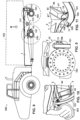
Fig. 1 is a top view of a chassis in accordance with a first embodiment; -
Fig. 2 is a side view of the chassis showing the left-hand beam; -
Figs. 3 and 4 are enlarged views of one suspension mount provided on the left-hand beam of the chassis as shown inFig. 2 , seen respectively from the inwardly and outwardly facing sides of the beam; -
Fig. 5 and 6 are partial sections through the suspension mount, taken just inwardly of the outer side plate at V - V ofFig. 1 ; -
Fig. 7 is another section taken through the suspension mount and the crossmember at VII - VII ofFigs. 1 and 2 ; -
Fig. 8 shows a vehicle equipped with the chassis; -
Fig. 9 is an enlarged view of the suspension mount as shown inFig. 8 ; and -
Figs. 10 and 11 are further views of the suspension mount as shown inFigs. 8 and 9 , seen respectively from the outwardly and inwardly facing sides of the beam. - Reference numerals and characters appearing in more than one of the figures indicate the same or corresponding parts in each of them.
- Referring to
Figs. 1 and 2 , achassis 1 for avehicle 100 may be fabricated for example from steel or other suitable metal, and has a major, length dimension Lc and minor, width Wc and height Hc dimensions (which is to say, the width and height dimensions are smaller than the length dimension). - The chassis includes a pair of first (left-hand) and second (right-hand)
beams 2, which is to say, the principal longitudinal elements of the chassis, often referred to as rails. The first andsecond beams 2 may be arranged in parallel relation or approximately parallel relation and are spaced apart in the width dimension Wc of the chassis, each beam extending in a length dimension Lb of the beam for at least most of the length dimension Lc of the chassis. Thebeams 2 may be connected together by a plurality ofcrossmembers beams 2 may be constant as illustrated, or may vary along the length dimension Lc to suit the configuration of the vehicle body and suspension as well known in the art. - Referring also to
Figs. 3-7 , eachbeam 2 includes a pair of first andsecond side plates 3 spaced apart in the width dimension Wc of the chassis. The side plates may be arranged in generally parallel relation. - Each side plate may consist of a single, shaped portion of a single piece of steel which was solidified from a molten condition to form said single piece of steel. That is to say, each
side plate 3 may be formed from a single piece of steel rather than fabricated from two or more pieces which are joined together, e.g. by welding. It will be understood that, irrespective of whether eachside plate 3 is formed from a single piece of steel, or fabricated from two or more pieces, each side plate may be locally reinforced by one or morestiffening plates 7 which may be welded to theside plate 3, e.g. as illustrated. - The first and
second side plates 3 are connected together by at least one web, which, as illustrated, may include anupper web 4 and alower web 5 spaced apart in the height dimension He of the chassis. - Each
side plate 3 has a length dimension Lp and extends in its length dimension Lp for the full length dimension Lb of thebeam 2. Thus, it will be understood that each side plate extends continuously between the opposite ends of thebeam 2. The at least oneweb 4, 5 (or either or each of the upper andlower webs 4, 5) may also extend for most or all of the length dimension Lb of thebeam 2. Thus, the length Lb of thebeam 2 may be defined by the length Lp of theside plates 3, or the length of theside plates 3 and the upper and/orlower web beam 2 in the height dimension He of the chassis; which is to say, the side plates and at least one web together are the principal loadbearing elements of the chassis. - In the illustrated example, the
side plates 3 are locally stiffened bystiffening plates 7 welded to the side plate on the outwardly facing side of each beam. - The upper and
lower webs plates 3 varies along their length dimension Lp, as best seen inFig. 6 . - Both the
upper web 4 and thelower web 5 may be welded to theside plates 3. Theupper web 4 may extend beyond theside plates 3 in the width dimension Wc of the chassis while thelower web 5 is contained between the side plates, as shown. - Each
beam 2 may define a hollow or box section between theparallel side plates 3 and upper andlower webs - The at least one web (or as illustrated, each of the upper and
lower webs 4, 5) has a minor, thickness dimension Tw in the height dimension He of the chassis, and extends between theside plates 3 in the length dimension Lc of the chassis, and in its width dimension Ww in the width dimension Wc of thechassis 1. - Each
side plate 3 has a major, length dimension Lp in the length dimension Lc of the chassis, a minor, height dimension Hp in the height dimension He of the chassis, and a thickness Tp in the width dimension Wc of the chassis. The thickness of course is much smaller than the length and width. - At least one of the
beams 2 further includes at least onesuspension mount 10 configured for connecting therespective beam 2 to asuspension member 101 of thevehicle 100 to transfer loads to the suspension member. - By suspension member is meant any member that transfers static or dynamic loads from the
chassis 1 directly or indirectly to a supporting or ground engaging (e.g. road wheel and axle)assembly 103 of the vehicle, which is movable relative to the chassis to absorb dynamic forces. In particular, thesuspension member 101 may be configured to transfer dynamic loads acting in the width dimension Wc of the chassis. In use, the at least onesuspension mount 10 may transfer loads from the chassis to the suspension member and from the suspension member to the chassis; for convenience, the action and reaction of the load transfer via the suspension mount is referred to herein simply as transferring loads to the suspension member. - Referring also to
Figs. 8 - 11 , typically the suspension system includesresilient elements 110 for absorbing dynamic forces and supporting the vertical load M applied by the mass of thevehicle body 102, as well as one or morePanhard rods 101 or other elements for transferring lateral loads acting generally in the width dimension Wc of the chassis between the chassis and theaxle assembly 103. In the illustrated example eachbeam 2 includes apivot 111 for transferring the load M via a walkingbeam suspension assembly 112 includingresilient elements 110 to a pair of centre andrear axle assemblies 103 which transfer the vertical load M via the wheels to the ground. - In the illustrated example, the
suspension member 101 comprises a rigid tie-bar or Panhard rod which is pivotably connected to thesuspension mount 10 and to thecentre axle assembly 103 to react lateral forces applied between the chassis and the centre axle assembly of the vehicle, as shown inFigs. 8 - 11 . One or more additional suspension mounts of the same construction as suspension mount 10 may be provided on one or bothbeams 2. In the illustrated example arear suspension mount 113 of different construction is also provided for connecting another Panhard rod to therear axle assembly 103. - As best seen in
Figs. 3 - 7 , thesuspension mount 10 is integrated into the primary structure of thebeam 2 so that it extends between theside plates 3 and connects theside plates 3 together, for example, being welded to theside plates 3 and/or thelower web 5. - The
suspension mount 10 includes, as illustrated, two (first and second)mount bodies 11', 11" spaced apart in the length dimension Lc of the chassis, wherein the or eachmount body 11', 11" extends between theside plates 3 in the height and width dimensions He, Wc of the chassis. Eachmount body 11', 11" may be welded to the side plates 3 (e.g. to the facing surfaces of the side plates 3), as shown. Eachmount body 11', 11" may also be welded to thelower web 5, as shown. Eachmount body 11', 11" may comprise a connection means such as a through-hole 12 to receivebolts 13 for connecting thesuspension member 101 to the mount. - Each
mount body 11', 11" may comprise an upper portion formed as a plate which is substantially contained between theside plates 3 as shown and connects the side plates together. The upper portion of the mount body may thus connect the mount body to the side plates and to thelower web 5, e.g. by welds. The connection means, e.g. through-hole 12, may be formed as shown in a lower portion of the respective mount body which may be welded to the upper portion and may extend in the width dimension Wc of the chassis somewhat beyond or through the thickness of the side plates. - The
suspension member 101 may be received between themount bodies 11', 11". Eachside plate 3 may define arecess 6 between themount bodies 11', 11" and opening at alower margin 32 of the side plate to accommodate an end region of thesuspension member 101, which may comprise a tie-bar 104 and a bushing orpivot assembly 105 which is arranged between themount bodies 11', 11" to provide a movement or shock-absorbing or pivotal connection between themount 10 and the tie-bar 104, as shown.Assembly 105 may comprise for example an elastomeric straddle bushing. - Optionally as shown, the
pivot assembly 105 may include a fixed connector orpivot axle 106 which is fixedly attached to themount bodies 11', 11" to extend between themount bodies 11', 11", wherein the tie-bar 104 is accommodated in therecess 6 and is movable or pivotable about thepivot axle 106. - As best seen in
Figs. 5 and 6 , alower portion 31 of eachside plate 3 of therespective beam 2 on which thesuspension mount 10 is arranged (or of each beam 2) may extend downwardly in the height dimension He of thechassis 1 below the at least one web (so, where upper andlower webs suspension mount 10 may be arranged below the at least one web orlower web 5 and between thelower portions 31 of theside plates 3 of therespective beam 2. - As shown in
Fig. 6 , a height dimension H31 of thelower portion 31 of eachside plate 3 of therespective beam 2 on which themount 10 is arranged, between the at least one web (so, thelower web 5 in the illustrated embodiment) and alower margin 32 of the side plate in the height dimension Hc of the chassis, may reduce progressively away from thesuspension mount 10 in the length dimension Lc of the chassis, in either or both of the forward and rearward directions of the chassis. Optionally, as can also be seen inFig. 6 , thelower margin 32 of eachside plate 3 proximate thesuspension mount 10 may be curved in the height dimension Hc of the chassis. For example, thelower margin 32 of the plate proximate themount 10 may be curved with constant radius or may have an elliptical curvature, either forward or rearward of themount 10 or (as shown) both forward and rearward of the mount with respect to the length direction of the chassis. - As shown, a
crossmember 40 is arranged to extend between thebeams 2 of the chassis and connected at a first one of its ends to a respective one of theside plates 3 of therespective beam 2 on which thesuspension mount 10 is arranged, proximate thesuspension mount 10. The crossmember may be connected at its other (second) end to the corresponding one of theside plates 3 of theopposite beam 2, so that it extends as shown inFig. 1 between theopposed side plates 3 of the twobeams 2. - If more than one
suspension mount 10 is provided, each may be supported by acrossmember 40 as shown. - As best seen in
Figs. 3, 4 and7 , thecrossmember 40 includes first andsecond crossmember plates - The first and
second crossmember plates lower crossmember webs plates webs webs crossmember plates - As illustrated, the
first crossmember plate 41' is connected to the respective one of theside plates 3 of therespective beam 2 on which the suspension mount is arranged, and proximate the first mount body 11' of thesuspension mount 10. Thesecond crossmember plate 41" is connected to that same respective one of theside plates 3 of that samerespective beam 2 on which the suspension mount is arranged, proximate thesecond mount body 11" of thesuspension mount 10. In this way the twocrossmember plates lower portion 31 of the samerespective side plate 3 of thebeam 2 on which the suspension mount is arranged, proximate the twomount bodies 11', 11". - As best seen in
Figs. 5 - 7 , a stiffening channel or insert 114 may be arranged within the box section formed between theside plates 3 and upper andlower webs aperture 115 may be formed in one of theside plates 3 to facilitate assembly. Thestiffening insert 114 may then be welded to one (e.g. the inward one, as shown) of theside plates 3 and to the upper and/orlower webs side plate 3 is added to close the box section. In a second operation, a face of thestiffening insert 114 can then be welded at the margin of the aperture to the remaining side plate 3 (in the illustrated example, the outer one of the side plates 3) to complete the assembly, as best seen inFig. 7 . - In summary, a
vehicle chassis 1 comprises a pair ofbeams 2, each beam having generallyparallel side plates 3 extending in height and length dimensions He, Lc of the chassis and joined by one ormore webs side plates 3 in the width dimension Wc, which together form its principal loadbearing elements. At least one of the beams includes at least onesuspension mount 10 which extends between theside plates 3 and connects theside plates 3 together. - The arrangement of the
suspension mount 10 between theside plates 3 of thechassis beam 2 may reduce stress concentrations by providing a more gradual change in stiffness along the length of thebeam 2. This can be enhanced by a progressive reduction in height H31 of thelower portion 31 of theside plate 3, particularly where thelower margin 32 of theside plate 3 is curved. The more gradual change in stiffness may reduce stress concentrations which in turn allows the overall weight of the beams to be reduced, with concomitant improvement in vehicle fuel efficiency, without reducing the durability of thechassis 1. - By forming each
side plate 3 as a unitary piece of steel rather than a fabricated assembly, the fatigue properties of the chassis in the region of thesuspension mount 10 are governed by the parent material of theside plate 3 rather than by the limitations of the welding or other fabrication technique used to attach the prior art mount, and so may be further improved. - The provision of a crossmember or
crossmembers 40 further enhances the strength-to-weight ratio of thebeam 2 in the region of themount 10, where the twoplates crossmember 40 are connected proximate the twomount bodies 11', 11" to provide stiffness out of the plane of theside plates 3 of thebeam 2. - The
novel chassis 1 may be used on vehicles including wheeled road vehicles 100 (which is to say, vehicles running on wheels that can be steered over a paved road or other ground surface). In particular, thenovel chassis 1 may provide improved lifespan or reduced costs in heavy vehicles, for example, trucks (including the tractor or trailer units of articulated trucks) or other road vehicles that have a gross weight, for example, of 10 tonnes or more. - Many further adaptations are possible as long as they fall under the scope of the claims.
- In the claims, reference numerals and characters are provided in parentheses, purely for ease of reference, and are not to be construed as limiting features.
-
- 1
- chassis
- 2
- beams
- 3
- side plate
- 4
- upper web
- 5
- lower web
- 6
- recess
- 7
- stiffening plates
- 10
- suspension mount
- 11'
- first mount body
- 11"
- second mount body
- 12
- through-hole
- 13
- bolt
- 31
- lower portion
- 32
- lower margin
- 40
- crossmember
- 41'
- first crossmember plate
- 41"
- second crossmember plate
- 42
- upper crossmember web
- 43
- lower crossmember web
- 50
- crossmember
- 100
- vehicle
- 101
- suspension member
- 102
- vehicle body
- 103
- axle assembly
- 104
- tie-bar
- 105
- pivot assembly
- 106
- fixed connector or pivot axle
- 110
- resilient elements
- 111
- pivot
- 112
- walking beam suspension assembly
- 113
- rear suspension mount
- 114
- stiffening insert
- 115
- aperture
- H31
- height dimension of lower portion
- He
- height dimension of chassis
- Hp
- height dimension of side plates
- Lc
- length dimension of chassis
- Lb
- length dimension of beam
- Lp
- length dimension of side plates
- M
- load
- Tp
- thickness dimension of side plates
- Tw
- thickness dimension of webs
- Wc
- width dimension of chassis
- Ww
- width dimension of webs
Claims (7)
- A chassis (1) for a vehicle (100), the chassis (1) having a major, length dimension (Lc) and minor, width (Wc) and height (Hc) dimensions, and includinga pair of beams (2) spaced apart in the width dimension (Wc) of the chassis (1), each beam (2) extending in a length dimension (Lb) of the beam (2) for at least most of the length dimension (Lc) of the chassis (1);each beam (2) including a pair of side plates (3) spaced apart in the width dimension (Wc) of the chassis (1) and connected together by at least one web (4, 5), the at least one web (4, 5) extending between the side plates (3) in the length and width dimensions (Lc, Wc) of the chassis (1);each side plate (3) having a major, length dimension (Lp) in the length dimension (Lc) of the chassis (1), a minor, height dimension (Hp) in the height dimension (Hc) of the chassis (1), and a thickness (Tp) in the width dimension (Wc) of the chassis (1), the length dimension (Lp) of each side plate (3) extending for the full length dimension (Lb) of the beam (2);the side plates (3) and the at least one web (4, 5) together being configured to transmit along the beam (2) in the length dimension (Lc) of the chassis (1) at least most of a bending moment applied by a load (M) to the beam (2) in the height dimension (Hc) of the chassis (1);at least one said beam (2) further including at least one suspension mount (10) configured for connecting the beam (2) to a suspension member (101) of the vehicle (100) to transfer loads to the suspension member (101);wherein the suspension mount (10) extends between the side plates (3) of the respective beam (2) and connects the side plates (3) together;the chassis further including a crossmember (40), wherein the crossmember (40) extends between the beams (2) of the chassis (1) and is connected to a respective one of the side plates (3) of said respective beam (2) proximate the suspension mount (10);characterised in thatthe crossmember (40) includes first and second crossmember plates (41', 41") extending in the width and height dimensions (Wc, Hc) of the chassis (1) and spaced apart in the length dimension (Lc) of the chassis (1);and the suspension mount (10) includes first and second mount bodies (11', 11") spaced apart in the length dimension (Lc) of the chassis (1), each mount body (11', 11") extending between the side plates (3) of said respective beam (2) in the height and width dimensions (Hc, Wc) of the chassis (1);and the first crossmember plate (41') is connected to said respective one of the side plates (3) of said respective beam (2) proximate the first mount body (11'),and the second crossmember plate (41") is connected to said respective one of the side plates (3) of said respective beam (2) proximate the second mount body (11").
- A chassis (1) according to claim 1, wherein a lower portion (31) of each side plate (3) of said respective beam (2) extends downwardly in the height dimension (Hc) of the chassis (1) below the at least one web (4, 5), and the suspension mount (10) is arranged below the at least one web (4, 5) and between the lower portions (31) of the side plates (3) of the respective beam (2).
- A chassis according to claim 2, wherein the at least one web (4,5) of each beam (2) includes an upper web (4) and a lower web (5) spaced apart in the height dimension (Hc) of the chassis (1).
- A chassis (1) according to claim 2, wherein a height dimension (H31) of the lower portion (31) of each side plate (3) of said respective beam (2) between the at least one web (5) and a lower margin (32) of the side plate (3) in the height dimension (Hc) of the chassis (1) reduces progressively away from the suspension mount (10) in the length dimension (Lc) of the chassis (1).
- A chassis (1) according to claim 4, wherein the lower margin (32) of each side plate (3) of said respective beam (2) proximate the suspension mount (10) is curved in the height dimension (Hc) of the chassis (1).
- A chassis according to claim 1, wherein each side plate (3) consists of a single, shaped portion of a single piece of steel which was solidified from a molten condition to form said single piece of steel.
- A vehicle (100) having a chassis (1) according to claim 1.
Applications Claiming Priority (2)
| Application Number | Priority Date | Filing Date | Title |
|---|---|---|---|
| GB1905875.9A GB2583381A (en) | 2019-04-26 | 2019-04-26 | Vehicle chassis having twin walled beams with suspension mounting structure |
| PCT/EP2020/050401 WO2020216478A1 (en) | 2019-04-26 | 2020-01-09 | Vehicle chassis having twin walled beams with suspension mounting structure |
Publications (2)
| Publication Number | Publication Date |
|---|---|
| EP3959116A1 EP3959116A1 (en) | 2022-03-02 |
| EP3959116B1 true EP3959116B1 (en) | 2023-08-23 |
Family
ID=66809104
Family Applications (1)
| Application Number | Title | Priority Date | Filing Date |
|---|---|---|---|
| EP20700663.6A Active EP3959116B1 (en) | 2019-04-26 | 2020-01-09 | Vehicle chassis having twin walled beams with suspension mounting structure |
Country Status (4)
| Country | Link |
|---|---|
| US (1) | US20220227421A1 (en) |
| EP (1) | EP3959116B1 (en) |
| GB (1) | GB2583381A (en) |
| WO (1) | WO2020216478A1 (en) |
Family Cites Families (13)
| Publication number | Priority date | Publication date | Assignee | Title |
|---|---|---|---|---|
| US2107382A (en) * | 1933-11-27 | 1938-02-08 | Midland Steel Prod Co | Vehicle frame |
| US6676160B2 (en) * | 2001-08-20 | 2004-01-13 | Ford Global Technologies, Llc | Rear frame rail that incorporates leaf spring clearance zone |
| US7207593B2 (en) * | 2004-03-22 | 2007-04-24 | Arvinmeritor Technology, Llc | Lightweight reinforced tractor-trailer slider |
| EP1957344B1 (en) * | 2005-11-18 | 2012-12-19 | Hendrickson International Corporation | Frame for heavy-duty vehicles |
| CN201300888Y (en) * | 2008-11-12 | 2009-09-02 | 中国第一汽车集团公司 | Bending longitudinal beam structure of mining self-dumping truck |
| JP5797517B2 (en) * | 2011-10-05 | 2015-10-21 | 日野自動車株式会社 | Body frame connecting member and body frame structure |
| CN104787119B (en) * | 2015-04-15 | 2017-01-25 | 吉林大学 | Design method of pure electric bus rear sub-frame |
| CN205768443U (en) * | 2015-11-30 | 2016-12-07 | 亨德里克森美国有限责任公司 | Frame hanging device bracket, frame hanging device assembly, suspension and foundry goods |
| US10215263B2 (en) * | 2016-06-28 | 2019-02-26 | Reyco Granning, Llc | Air spring actuated slider for semi-trailer |
| WO2018016051A1 (en) * | 2016-07-21 | 2018-01-25 | 日産ライトトラック株式会社 | Frame for vehicles |
| US10449817B2 (en) * | 2017-05-18 | 2019-10-22 | Hendrickson Usa, L.L.C. | Slider wear pad |
| US10507870B2 (en) * | 2017-11-07 | 2019-12-17 | Cnh Industrial America Llc | Calibrated frame stiffness gradient in an agricultural product sprayer |
| US10696114B2 (en) * | 2018-11-26 | 2020-06-30 | Kubota Corporation | Utility vehicle |
-
2019
- 2019-04-26 GB GB1905875.9A patent/GB2583381A/en not_active Withdrawn
-
2020
- 2020-01-09 WO PCT/EP2020/050401 patent/WO2020216478A1/en unknown
- 2020-01-09 EP EP20700663.6A patent/EP3959116B1/en active Active
- 2020-01-09 US US17/606,564 patent/US20220227421A1/en active Pending
Also Published As
| Publication number | Publication date |
|---|---|
| US20220227421A1 (en) | 2022-07-21 |
| GB2583381A (en) | 2020-10-28 |
| GB201905875D0 (en) | 2019-06-12 |
| WO2020216478A1 (en) | 2020-10-29 |
| EP3959116A1 (en) | 2022-03-02 |
Similar Documents
| Publication | Publication Date | Title |
|---|---|---|
| AU2006342140B2 (en) | Frame for heavy-duty vehicles | |
| US7455306B2 (en) | Integral arm axle/suspension system | |
| CA2538732C (en) | Movable subframe for semi-trailers | |
| US6428046B1 (en) | Front cradle for a vehicle | |
| EP2125495A1 (en) | A chassis frame especially for a heavy vehicle | |
| AU2004282200B2 (en) | Integral arm axle/suspension system | |
| US5971425A (en) | Suspension system for a load carrying machine | |
| CN213384446U (en) | Frame for truck | |
| EP3959116B1 (en) | Vehicle chassis having twin walled beams with suspension mounting structure | |
| EP2429839B1 (en) | Trailing arm mounting bracket | |
| CN101224757B (en) | Car front beam | |
| US9096273B2 (en) | Apparatus for reinforcing a supporting subframe | |
| CN201217449Y (en) | Front beam of automobile | |
| WO2004020268A1 (en) | Chassis frame for a truck | |
| JP4580532B2 (en) | Suspension mounting structure | |
| KR100373029B1 (en) | Front suspension cross member of vehicle | |
| CN220615948U (en) | Frame structure | |
| NL2031947B1 (en) | Bearing bracket | |
| EP3929065B1 (en) | Mounting chassis | |
| KR20150001824U (en) | Flat board trailer | |
| CN116902073A (en) | Frame structure | |
| MXPA06004209A (en) | Integral arm axle/suspension system | |
| MXPA06003994A (en) | Movable subframe for semi-trailers |
Legal Events
| Date | Code | Title | Description |
|---|---|---|---|
| STAA | Information on the status of an ep patent application or granted ep patent |
Free format text: STATUS: UNKNOWN |
|
| STAA | Information on the status of an ep patent application or granted ep patent |
Free format text: STATUS: THE INTERNATIONAL PUBLICATION HAS BEEN MADE |
|
| PUAI | Public reference made under article 153(3) epc to a published international application that has entered the european phase |
Free format text: ORIGINAL CODE: 0009012 |
|
| STAA | Information on the status of an ep patent application or granted ep patent |
Free format text: STATUS: REQUEST FOR EXAMINATION WAS MADE |
|
| 17P | Request for examination filed |
Effective date: 20210927 |
|
| AK | Designated contracting states |
Kind code of ref document: A1 Designated state(s): AL AT BE BG CH CY CZ DE DK EE ES FI FR GB GR HR HU IE IS IT LI LT LU LV MC MK MT NL NO PL PT RO RS SE SI SK SM TR |
|
| DAV | Request for validation of the european patent (deleted) | ||
| DAX | Request for extension of the european patent (deleted) | ||
| REG | Reference to a national code |
Ref country code: DE Ref legal event code: R079 Ref document number: 602020016215 Country of ref document: DE Free format text: PREVIOUS MAIN CLASS: B62D0021020000 Ipc: B62D0021110000 Ref country code: DE Ref legal event code: R079 Free format text: PREVIOUS MAIN CLASS: B62D0021020000 Ipc: B62D0021110000 |
|
| GRAP | Despatch of communication of intention to grant a patent |
Free format text: ORIGINAL CODE: EPIDOSNIGR1 |
|
| STAA | Information on the status of an ep patent application or granted ep patent |
Free format text: STATUS: GRANT OF PATENT IS INTENDED |
|
| RIC1 | Information provided on ipc code assigned before grant |
Ipc: B60G 7/02 20060101ALI20230222BHEP Ipc: B60G 7/00 20060101ALI20230222BHEP Ipc: B60G 5/02 20060101ALI20230222BHEP Ipc: B62D 21/02 20060101ALI20230222BHEP Ipc: B62D 21/11 20060101AFI20230222BHEP |
|
| INTG | Intention to grant announced |
Effective date: 20230316 |
|
| GRAS | Grant fee paid |
Free format text: ORIGINAL CODE: EPIDOSNIGR3 |
|
| GRAA | (expected) grant |
Free format text: ORIGINAL CODE: 0009210 |
|
| STAA | Information on the status of an ep patent application or granted ep patent |
Free format text: STATUS: THE PATENT HAS BEEN GRANTED |
|
| P01 | Opt-out of the competence of the unified patent court (upc) registered |
Effective date: 20230622 |
|
| AK | Designated contracting states |
Kind code of ref document: B1 Designated state(s): AL AT BE BG CH CY CZ DE DK EE ES FI FR GB GR HR HU IE IS IT LI LT LU LV MC MK MT NL NO PL PT RO RS SE SI SK SM TR |
|
| REG | Reference to a national code |
Ref country code: GB Ref legal event code: FG4D |
|
| REG | Reference to a national code |
Ref country code: CH Ref legal event code: EP |
|
| REG | Reference to a national code |
Ref country code: DE Ref legal event code: R096 Ref document number: 602020016215 Country of ref document: DE |
|
| REG | Reference to a national code |
Ref country code: IE Ref legal event code: FG4D |
|
| REG | Reference to a national code |
Ref country code: SE Ref legal event code: TRGR |
|
| REG | Reference to a national code |
Ref country code: LT Ref legal event code: MG9D |
|
| REG | Reference to a national code |
Ref country code: NL Ref legal event code: MP Effective date: 20230823 |
|
| REG | Reference to a national code |
Ref country code: AT Ref legal event code: MK05 Ref document number: 1602289 Country of ref document: AT Kind code of ref document: T Effective date: 20230823 |
|
| PG25 | Lapsed in a contracting state [announced via postgrant information from national office to epo] |
Ref country code: GR Free format text: LAPSE BECAUSE OF FAILURE TO SUBMIT A TRANSLATION OF THE DESCRIPTION OR TO PAY THE FEE WITHIN THE PRESCRIBED TIME-LIMIT Effective date: 20231124 |
|
| PGFP | Annual fee paid to national office [announced via postgrant information from national office to epo] |
Ref country code: GB Payment date: 20231219 Year of fee payment: 5 |
|
| PG25 | Lapsed in a contracting state [announced via postgrant information from national office to epo] |
Ref country code: IS Free format text: LAPSE BECAUSE OF FAILURE TO SUBMIT A TRANSLATION OF THE DESCRIPTION OR TO PAY THE FEE WITHIN THE PRESCRIBED TIME-LIMIT Effective date: 20231223 |
|
| PG25 | Lapsed in a contracting state [announced via postgrant information from national office to epo] |
Ref country code: RS Free format text: LAPSE BECAUSE OF FAILURE TO SUBMIT A TRANSLATION OF THE DESCRIPTION OR TO PAY THE FEE WITHIN THE PRESCRIBED TIME-LIMIT Effective date: 20230823 Ref country code: PT Free format text: LAPSE BECAUSE OF FAILURE TO SUBMIT A TRANSLATION OF THE DESCRIPTION OR TO PAY THE FEE WITHIN THE PRESCRIBED TIME-LIMIT Effective date: 20231226 Ref country code: NO Free format text: LAPSE BECAUSE OF FAILURE TO SUBMIT A TRANSLATION OF THE DESCRIPTION OR TO PAY THE FEE WITHIN THE PRESCRIBED TIME-LIMIT Effective date: 20231123 Ref country code: NL Free format text: LAPSE BECAUSE OF FAILURE TO SUBMIT A TRANSLATION OF THE DESCRIPTION OR TO PAY THE FEE WITHIN THE PRESCRIBED TIME-LIMIT Effective date: 20230823 Ref country code: LV Free format text: LAPSE BECAUSE OF FAILURE TO SUBMIT A TRANSLATION OF THE DESCRIPTION OR TO PAY THE FEE WITHIN THE PRESCRIBED TIME-LIMIT Effective date: 20230823 Ref country code: LT Free format text: LAPSE BECAUSE OF FAILURE TO SUBMIT A TRANSLATION OF THE DESCRIPTION OR TO PAY THE FEE WITHIN THE PRESCRIBED TIME-LIMIT Effective date: 20230823 Ref country code: IS Free format text: LAPSE BECAUSE OF FAILURE TO SUBMIT A TRANSLATION OF THE DESCRIPTION OR TO PAY THE FEE WITHIN THE PRESCRIBED TIME-LIMIT Effective date: 20231223 Ref country code: HR Free format text: LAPSE BECAUSE OF FAILURE TO SUBMIT A TRANSLATION OF THE DESCRIPTION OR TO PAY THE FEE WITHIN THE PRESCRIBED TIME-LIMIT Effective date: 20230823 Ref country code: GR Free format text: LAPSE BECAUSE OF FAILURE TO SUBMIT A TRANSLATION OF THE DESCRIPTION OR TO PAY THE FEE WITHIN THE PRESCRIBED TIME-LIMIT Effective date: 20231124 Ref country code: FI Free format text: LAPSE BECAUSE OF FAILURE TO SUBMIT A TRANSLATION OF THE DESCRIPTION OR TO PAY THE FEE WITHIN THE PRESCRIBED TIME-LIMIT Effective date: 20230823 Ref country code: AT Free format text: LAPSE BECAUSE OF FAILURE TO SUBMIT A TRANSLATION OF THE DESCRIPTION OR TO PAY THE FEE WITHIN THE PRESCRIBED TIME-LIMIT Effective date: 20230823 |
|
| PGFP | Annual fee paid to national office [announced via postgrant information from national office to epo] |
Ref country code: SE Payment date: 20231219 Year of fee payment: 5 |
|
| PG25 | Lapsed in a contracting state [announced via postgrant information from national office to epo] |
Ref country code: PL Free format text: LAPSE BECAUSE OF FAILURE TO SUBMIT A TRANSLATION OF THE DESCRIPTION OR TO PAY THE FEE WITHIN THE PRESCRIBED TIME-LIMIT Effective date: 20230823 |