EP3959090B1 - Electric traction vehicle - Google Patents
Electric traction vehicle Download PDFInfo
- Publication number
- EP3959090B1 EP3959090B1 EP21733537.1A EP21733537A EP3959090B1 EP 3959090 B1 EP3959090 B1 EP 3959090B1 EP 21733537 A EP21733537 A EP 21733537A EP 3959090 B1 EP3959090 B1 EP 3959090B1
- Authority
- EP
- European Patent Office
- Prior art keywords
- air
- chassis
- passenger compartment
- air conditioning
- electric vehicle
- Prior art date
- Legal status (The legal status is an assumption and is not a legal conclusion. Google has not performed a legal analysis and makes no representation as to the accuracy of the status listed.)
- Active
Links
Images


Classifications
-
- B—PERFORMING OPERATIONS; TRANSPORTING
- B60—VEHICLES IN GENERAL
- B60H—ARRANGEMENTS OF HEATING, COOLING, VENTILATING OR OTHER AIR-TREATING DEVICES SPECIALLY ADAPTED FOR PASSENGER OR GOODS SPACES OF VEHICLES
- B60H1/00—Heating, cooling or ventilating devices
- B60H1/00642—Control systems or circuits; Control members or indication devices for heating, cooling or ventilating devices
- B60H1/00735—Control systems or circuits characterised by their input, i.e. by the detection, measurement or calculation of particular conditions, e.g. signal treatment, dynamic models
- B60H1/00764—Control systems or circuits characterised by their input, i.e. by the detection, measurement or calculation of particular conditions, e.g. signal treatment, dynamic models the input being a vehicle driving condition, e.g. speed
- B60H1/00778—Control systems or circuits characterised by their input, i.e. by the detection, measurement or calculation of particular conditions, e.g. signal treatment, dynamic models the input being a vehicle driving condition, e.g. speed the input being a stationary vehicle position, e.g. parking or stopping
-
- B—PERFORMING OPERATIONS; TRANSPORTING
- B60—VEHICLES IN GENERAL
- B60H—ARRANGEMENTS OF HEATING, COOLING, VENTILATING OR OTHER AIR-TREATING DEVICES SPECIALLY ADAPTED FOR PASSENGER OR GOODS SPACES OF VEHICLES
- B60H1/00—Heating, cooling or ventilating devices
- B60H1/00357—Air-conditioning arrangements specially adapted for particular vehicles
- B60H1/00385—Air-conditioning arrangements specially adapted for particular vehicles for vehicles having an electrical drive, e.g. hybrid or fuel cell
- B60H1/00392—Air-conditioning arrangements specially adapted for particular vehicles for vehicles having an electrical drive, e.g. hybrid or fuel cell for electric vehicles having only electric drive means
-
- B—PERFORMING OPERATIONS; TRANSPORTING
- B60—VEHICLES IN GENERAL
- B60H—ARRANGEMENTS OF HEATING, COOLING, VENTILATING OR OTHER AIR-TREATING DEVICES SPECIALLY ADAPTED FOR PASSENGER OR GOODS SPACES OF VEHICLES
- B60H1/00—Heating, cooling or ventilating devices
- B60H1/22—Heating, cooling or ventilating devices the heat source being other than the propulsion plant
- B60H1/2215—Heating, cooling or ventilating devices the heat source being other than the propulsion plant the heat being derived from electric heaters
- B60H1/2218—Heating, cooling or ventilating devices the heat source being other than the propulsion plant the heat being derived from electric heaters controlling the operation of electric heaters
-
- B—PERFORMING OPERATIONS; TRANSPORTING
- B60—VEHICLES IN GENERAL
- B60L—PROPULSION OF ELECTRICALLY-PROPELLED VEHICLES; SUPPLYING ELECTRIC POWER FOR AUXILIARY EQUIPMENT OF ELECTRICALLY-PROPELLED VEHICLES; ELECTRODYNAMIC BRAKE SYSTEMS FOR VEHICLES IN GENERAL; MAGNETIC SUSPENSION OR LEVITATION FOR VEHICLES; MONITORING OPERATING VARIABLES OF ELECTRICALLY-PROPELLED VEHICLES; ELECTRIC SAFETY DEVICES FOR ELECTRICALLY-PROPELLED VEHICLES
- B60L1/00—Supplying electric power to auxiliary equipment of vehicles
- B60L1/02—Supplying electric power to auxiliary equipment of vehicles to electric heating circuits
-
- B—PERFORMING OPERATIONS; TRANSPORTING
- B60—VEHICLES IN GENERAL
- B60R—VEHICLES, VEHICLE FITTINGS, OR VEHICLE PARTS, NOT OTHERWISE PROVIDED FOR
- B60R13/00—Elements for body-finishing, identifying, or decorating; Arrangements or adaptations for advertising purposes
- B60R13/08—Insulating elements, e.g. for sound insulation
- B60R13/0876—Insulating elements, e.g. for sound insulation for mounting around heat sources, e.g. exhaust pipes
-
- B—PERFORMING OPERATIONS; TRANSPORTING
- B60—VEHICLES IN GENERAL
- B60H—ARRANGEMENTS OF HEATING, COOLING, VENTILATING OR OTHER AIR-TREATING DEVICES SPECIALLY ADAPTED FOR PASSENGER OR GOODS SPACES OF VEHICLES
- B60H1/00—Heating, cooling or ventilating devices
- B60H1/00271—HVAC devices specially adapted for particular vehicle parts or components and being connected to the vehicle HVAC unit
- B60H2001/003—Component temperature regulation using an air flow
-
- Y—GENERAL TAGGING OF NEW TECHNOLOGICAL DEVELOPMENTS; GENERAL TAGGING OF CROSS-SECTIONAL TECHNOLOGIES SPANNING OVER SEVERAL SECTIONS OF THE IPC; TECHNICAL SUBJECTS COVERED BY FORMER USPC CROSS-REFERENCE ART COLLECTIONS [XRACs] AND DIGESTS
- Y02—TECHNOLOGIES OR APPLICATIONS FOR MITIGATION OR ADAPTATION AGAINST CLIMATE CHANGE
- Y02T—CLIMATE CHANGE MITIGATION TECHNOLOGIES RELATED TO TRANSPORTATION
- Y02T10/00—Road transport of goods or passengers
- Y02T10/60—Other road transportation technologies with climate change mitigation effect
- Y02T10/70—Energy storage systems for electromobility, e.g. batteries
Definitions
- the invention relates to an electric vehicle comprising at least one electric motor connected to drive wheels and an air conditioning system that can also be activated when the vehicle is parked and to a control method of said electric vehicle.
- the invention finds advantageous application in an electric drive car, to which explicit reference will be made in the description below without because of this loosing in generality.
- the main problem affecting current electric drive cars is the range, since automotive batteries are capable of storing a relatively limited quantity of energy and have very long charging times (compared to petrol or Diesel refuelling times of cars provided with an internal combustion engine). Furthermore, the relatively small range of an electric drive car can further be reduced if, during the travel, the air conditioning system is used to heat or cool the passenger compartment because the temperature on the outside of the car is particularly hostile (namely, it is very cold or very hot).
- the heat produced by the combustion which constitutes a loss of energy for the purposes of powering the vehicle, can be used "for free” in order to heat the passenger compartment, whereas the same does not apply to an electric drive vehicle, for the efficiency of the powertrain is so high that it is not possible (convenient) to use the waste heat generated by the electric motors, by the electronic power converters and by the electric energy storage devices.
- the quantity of electric energy saved is significant (when the external temperature is particularly hostile), since, during the travel, the air conditioning system is used for the sole purpose of maintaining the desired temperature already present and does not need to be used to allow the passenger compartment to go from the environmental temperature to the desired temperature (with temperature differences than can amount to dozens of degrees Celsius in the middle of the winter or of the summer).
- the driver sets the travel beginning time and, hence, the air conditioning system is automatically activated (using the electric energy provided by the charging system) with a suitable advance so as to allow the passenger compartment to reach the desired temperature at the exact travel beginning time.
- Patent application DE102010043335A1 and patent application DE102018004839A1 disclose an electric drive vehicle, in which the passenger compartment air conditioning system is activated when the vehicle is parked and connected to an external energy source, so that the passenger compartment already has the desired temperature when the driver gets on board the vehicle to start a travel.
- Patent DE494879C describes an induction heating device for the chassis of a motor vehicle.
- Patent application JPH1142924 discloses a car in which the door sills (namely, the part of the chassis located under the doors) are internally hollow and are used as pneumatic channels to feed (hot or cold) conditioned air generated by an air conditioning system located in a front position towards the rear doors, so that said conditioned air can be diffused through the rear doors in the area of the rear seats.
- the object of the invention is to provide an electric vehicle comprising at least one electric motor connected to drive wheels and an air conditioning system that can also be activated when the vehicle is parked and a control method of said electric vehicle, said electric vehicle not being affected by the drawbacks described above and, at the same time, being easy and economic to be manufactured.
- an electric vehicle comprising at least one electric motor connected to drive wheels and an air conditioning system that can also be activated when the vehicle is parked and a control method of said electric vehicle, according to the appended independent claims.
- number 1 indicates, as a whole, a car with a rear (or central) motor comprising a chassis 2 (schematically shown in figures 2 and 3 ), which supports a pair of front wheels 3 and a pair of rear wheels 4).
- a passenger compartment 5 Between the front wheels 3 and the rear wheels 4 there is a passenger compartment 5, to which access is granted through a pair of doors 6; at the front the passenger compartment 5 is delimited by a windshield 7.
- a front compartment 8 In front of the passenger compartment 5 there is a front compartment 8 (for example, though not exclusively, for baggage), which is closed at the top by a front hinged hood 9.
- a rear motor compartment Behind the passenger compartment 5 there is a rear motor compartment, which is closed at the top by a rear hinged hood.
- the car 1 has an electric drive (powertrain) and comprises two electric motors 10, each connected to a corresponding rear drive wheel 3 by means of a mechanical drivetrain 11 (for example comprising an epicyclic gearing).
- a mechanical drivetrain 11 for example comprising an epicyclic gearing.
- Each electric motor 10 is controlled by a corresponding electronic power converter 12, which provides the corresponding stator winding with an AC voltage and exchanges electric energy with a storage device 13.
- a cable - to an external charging system 14, which supplies the storage device 13 with electric energy.
- the chassis 2 comprises a set of internally hollow boxed elements 15; said boxed elements 15 consist, for example, of internally hollow linear bars, which are made of a light metal alloy (generally speaking, an aluminium-based alloy), are manufactured through extrusion and are joined to one another by means of welding in the area of structural nodes preferably defined by joining bodies.
- a light metal alloy generally speaking, an aluminium-based alloy
- the car 1 comprises an air conditioning system 16, which is designed to air condition the passenger compartment 5 by heating or cooling the air present in the passenger compartment 5.
- the air conditioning system 16 comprises one or more fans 17, which are operated by respective electric motors and are designed to generated a forced air circulation, and an air treatment unit 18, which is designed to cool or heat the air that is caused to circulate by the fans 17; typically, the air treatment unit 18 comprises a heat pump, which is operated by an electric motor.
- the air conditioning system 16 comprises a thermal device 19, which is designed to directly exchange heat with the sole chassis 2; namely, the thermal device 19 is not capable of exchanging heat with the passenger compartment 5, since it is completely dedicated to operating with the sole chassis 2.
- the car 1 comprises a control unit 20, which is configured to activate the air conditioning system 16 also when the vehicle 1 is parked and connected to the external charging system 14 (so as not to use the electric energy stored in the storage device 13); in particular, when the vehicle 1 is parked and connected to the external charging system 14, the control unit 20 activates the air conditioning system 16 both to air condition the passenger compartment 5 and (using the thermal device 19) to heat the chassis 2 (when the air conditioning requires the heating of the passenger compartment 5) or to cool the chassis 2 (when the air conditioning requires the cooling of the passenger compartment 5).
- the control unit 20 activates the air conditioning system 16 both to air condition the passenger compartment 5 and (using the thermal device 19) to heat the chassis 2 (when the air conditioning requires the heating of the passenger compartment 5) or to cool the chassis 2 (when the air conditioning requires the cooling of the passenger compartment 5).
- the thermal device 19 comprises a feeding member 21, which is configured to feed at least part of the air treated by the treatment unit 18 into the chassis 2; namely, thanks to the feeding member 21, at least part of the air treated by the air treatment unit 18 is fed into the chassis 2 instead of reaching the passenger compartment 5.
- the chassis 2 comprises at least one inlet opening 22, through which the air treated by the air treatment unit 18 enters the chassis 2, and at least one outlet opening 23, through which the air exits the chassis 2.
- the treatment unit 18 is configured to completely recirculate the air flowing out of the chassis 2 from the outlet opening 23; namely, in order to heat or cool the chassis 2, the same air used without using (as much as possible) air coming from the outside.
- the inlet opening 22 and the outlet opening 23 are close to one another on the same side of the chassis 2 so that the air coming from the outlet opening 23 can be conditioned again and then re-introduced into the inlet opening 22 covering a relatively short path (namely, making the air recirculation simpler and more efficient).
- a first path for the circulation of the air treated by the air conditioning system 16 and intended for the air conditioning of the passenger compartment 5 is different and completely isolated from a second path for the circulation of the air treated by the air conditioning system 16 and intended for the heating or cooling of the chassis 2, so that the air circulating in the passenger compartment 2 never mixes with the air circulating through the chassis 2.
- the air treated by the air conditioning system 16 and intended for the air conditioning of the passenger compartment 5 is different and always separate from the air treated by the air conditioning system 16 and intended for the heating or cooling of the chassis 2.
- the two air paths only share the source of heat or cold (consisting of one single common heat or cold generator of the air conditioning system 16), but do not share the same air, so that the air circulating in the passenger compartment 5 is isolated from the air circulating through the chassis 2.
- the chassis 2 internally comprises at least one dividing wall 24, which separates the inlet opening 22 from the outlet opening 23 so as to create, inside the chassis 2, a longer obligatory path, which is as varied as possible, between the inlet opening 22 and the outlet opening 23 (in this way, the air fed into the chassis 2, by flowing through the inlet opening 22, reaches as much of the chassis 2 as possible before getting to the outlet opening 23).
- the air treatment unit 18 is configured to introduce air at the same temperature into the passenger compartment 5 and into the chassis 2; as a consequence, the air treatment unit 18 carries out the same heat exchange both for the air introduced into the passenger compartment 5 and for the air introduced into the chassis 2.
- the air treatment unit 18 is configured to introduce into the passenger compartment 5 colder air, when the air conditioning involves heating, or hotter air, when the air conditioning involves cooling, compared to the air introduced into the chassis 2; as a consequence, the air treatment unit 18 carries out different thermal treatments for the air introduced into the passenger compartment 5 and the air introduced into the chassis 2.
- This embodiment is more complex in that it requires a differentiated air treatment in the air treatment unit 18, though it offers the advantage of cooling or heating the chassis 2 to greater extent than the one to which the passenger compartment 5 is cooled or heated, so as to store in the chassis 2 a greater quantity of heat or cold; to this regard, it should be pointed out that the passenger compartment 5 should have a temperature of circa 18-20 degrees Celsius in the winter and circa 26-28 degrees Celsius in the summer, whereas the chassis 2 can easily reach temperatures ranging from -10°C (even in the summer) to +60°C (even in the winter).
- the thermal device 19 could further comprise at least one electric heater 25, which is mounted on the chassis 2 so as to heat the chassis 2 through conduction; typically, the electric heater 25 comprises a resistance, which generates heat through Joule effect when an electric current flows through it.
- a thermal insulation 26 (schematically shown in figure 2 ) is provided, which is arranged between the chassis 2 and the outside (especially, though not exclusively, between the chassis 2 and the road surface) and is not interposed between the chassis 2 and the passenger compartment 5.
- the function of the thermal insulation 26 is that of reducing the exchange of heat between the chassis 2 and the outside, though encouraging the exchange of heat between the chassis 2 and the passenger compartment 5.
- the invention is applied to a car 1, but it can obviously be applied to a different type of vehicle having a closed passenger compartment (for example a van, a truck, a bus).
- a closed passenger compartment for example a van, a truck, a bus.
- the car 1 described above has numerous advantages.
- the passenger compartment 5 preserves the desired temperature much longer, even without the activation of the air conditioning system 16, thanks to the fact that the passenger compartment 5 is not surrounded by the chassis 2 having the external temperature, but is surrounded by the chassis 2 having (at first) the same temperature as the passenger compartment 5 or even a lower temperature than the passenger compartment 5 (when the air conditioning involves cooling) or a higher temperature than the passenger compartment 5 (when the air conditioning involves heating).
- thermal energy hot in the winter, cold in the summer
- a significant part of the mass of the car 1 namely, the chassis 2 and also the parts exchanging heat with the chassis 2 through conduction
- thermal energy can then be used by the passenger compartment 5 in order to preserve, during the first travel phase, ideal temperatures without having to use a significant action of the air conditioning system 16, which, in order to operate, necessarily has to use the electric energy stored in the storage device 13 (hence, reducing the range of the vehicle).
Landscapes
- Engineering & Computer Science (AREA)
- Mechanical Engineering (AREA)
- Physics & Mathematics (AREA)
- Thermal Sciences (AREA)
- Life Sciences & Earth Sciences (AREA)
- Sustainable Development (AREA)
- Sustainable Energy (AREA)
- Power Engineering (AREA)
- Transportation (AREA)
- Acoustics & Sound (AREA)
- Air-Conditioning For Vehicles (AREA)
- Arrangement Or Mounting Of Propulsion Units For Vehicles (AREA)
Description
- The invention relates to an electric vehicle comprising at least one electric motor connected to drive wheels and an air conditioning system that can also be activated when the vehicle is parked and to a control method of said electric vehicle.
- The invention finds advantageous application in an electric drive car, to which explicit reference will be made in the description below without because of this loosing in generality.
- The main problem affecting current electric drive cars is the range, since automotive batteries are capable of storing a relatively limited quantity of energy and have very long charging times (compared to petrol or Diesel refuelling times of cars provided with an internal combustion engine). Furthermore, the relatively small range of an electric drive car can further be reduced if, during the travel, the air conditioning system is used to heat or cool the passenger compartment because the temperature on the outside of the car is particularly hostile (namely, it is very cold or very hot). Besides, during the coldest months of the year, in a heat vehicle (namely a vehicle provided with an internal combustion engine), the heat produced by the combustion, which constitutes a loss of energy for the purposes of powering the vehicle, can be used "for free" in order to heat the passenger compartment, whereas the same does not apply to an electric drive vehicle, for the efficiency of the powertrain is so high that it is not possible (convenient) to use the waste heat generated by the electric motors, by the electronic power converters and by the electric energy storage devices.
- In order to reduce the use of the air conditioning system during the travel (and, especially, along the first kilometres of the path), thus reducing the electric energy used by the air conditioning system, manufacturers suggested using the air conditioning system (shortly) before the beginning of the travel, when the electric drive car is still connected to a charging system; in this way, the passenger compartment can reach the desired temperature not by using the electric energy stored in the battery of the electric drive car, but by using the electric energy provided by the network. The quantity of electric energy saved is significant (when the external temperature is particularly hostile), since, during the travel, the air conditioning system is used for the sole purpose of maintaining the desired temperature already present and does not need to be used to allow the passenger compartment to go from the environmental temperature to the desired temperature (with temperature differences than can amount to dozens of degrees Celsius in the middle of the winter or of the summer).
- Basically, when the electric drive car is parked and connected to a charging system, the driver sets the travel beginning time and, hence, the air conditioning system is automatically activated (using the electric energy provided by the charging system) with a suitable advance so as to allow the passenger compartment to reach the desired temperature at the exact travel beginning time.
- However, when the external temperature is particularly hostile (namely, it is very cold or very hot), as soon as the travel starts, the passenger compartment tends to exchange a relatively large quantity of heat with the outside and, therefore, the air conditioning system almost immediately has significant energy consumptions.
- Patent application
DE102010043335A1 and patent applicationDE102018004839A1 disclose an electric drive vehicle, in which the passenger compartment air conditioning system is activated when the vehicle is parked and connected to an external energy source, so that the passenger compartment already has the desired temperature when the driver gets on board the vehicle to start a travel. - Patent
DE494879C describes an induction heating device for the chassis of a motor vehicle. - Patent application
JPH1142924 - The object of the invention is to provide an electric vehicle comprising at least one electric motor connected to drive wheels and an air conditioning system that can also be activated when the vehicle is parked and a control method of said electric vehicle, said electric vehicle not being affected by the drawbacks described above and, at the same time, being easy and economic to be manufactured.
- According to the invention, there are provided an electric vehicle comprising at least one electric motor connected to drive wheels and an air conditioning system that can also be activated when the vehicle is parked and a control method of said electric vehicle, according to the appended independent claims.
- The appended dependent claims describe preferred embodiments of the invention.
- The invention will now be described with reference to the accompanying drawings, showing a non-limiting embodiment thereof, wherein:
-
figure 1 is a perspective view of an electric vehicle according to the invention; -
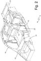
figure 2 is a schematic perspective view of a chassis of the vehicle offigure 1 ; and -
figure 3 is a schematic plan view of the vehicle offigure 1 . - In
figure 1 ,number 1 indicates, as a whole, a car with a rear (or central) motor comprising a chassis 2 (schematically shown infigures 2 and3 ), which supports a pair offront wheels 3 and a pair of rear wheels 4). - Between the
front wheels 3 and therear wheels 4 there is apassenger compartment 5, to which access is granted through a pair ofdoors 6; at the front thepassenger compartment 5 is delimited by awindshield 7. In front of thepassenger compartment 5 there is a front compartment 8 (for example, though not exclusively, for baggage), which is closed at the top by a front hingedhood 9. Behind thepassenger compartment 5 there is a rear motor compartment, which is closed at the top by a rear hinged hood. - According to
figure 3 , thecar 1 has an electric drive (powertrain) and comprises twoelectric motors 10, each connected to a correspondingrear drive wheel 3 by means of a mechanical drivetrain 11 (for example comprising an epicyclic gearing). Eachelectric motor 10 is controlled by a correspondingelectronic power converter 12, which provides the corresponding stator winding with an AC voltage and exchanges electric energy with astorage device 13. According tofigure 1 , when thecar 1 is parked, it can be connected - through a cable - to anexternal charging system 14, which supplies thestorage device 13 with electric energy. - According to
figures 2 and3 , thechassis 2 comprises a set of internally hollow boxedelements 15; said boxedelements 15 consist, for example, of internally hollow linear bars, which are made of a light metal alloy (generally speaking, an aluminium-based alloy), are manufactured through extrusion and are joined to one another by means of welding in the area of structural nodes preferably defined by joining bodies. - According to
figure 3 , thecar 1 comprises anair conditioning system 16, which is designed to air condition thepassenger compartment 5 by heating or cooling the air present in thepassenger compartment 5. In particular, theair conditioning system 16 comprises one ormore fans 17, which are operated by respective electric motors and are designed to generated a forced air circulation, and anair treatment unit 18, which is designed to cool or heat the air that is caused to circulate by thefans 17; typically, theair treatment unit 18 comprises a heat pump, which is operated by an electric motor. Furthermore, theair conditioning system 16 comprises athermal device 19, which is designed to directly exchange heat with thesole chassis 2; namely, thethermal device 19 is not capable of exchanging heat with thepassenger compartment 5, since it is completely dedicated to operating with thesole chassis 2. - Finally, the
car 1 comprises acontrol unit 20, which is configured to activate theair conditioning system 16 also when thevehicle 1 is parked and connected to the external charging system 14 (so as not to use the electric energy stored in the storage device 13); in particular, when thevehicle 1 is parked and connected to theexternal charging system 14, thecontrol unit 20 activates theair conditioning system 16 both to air condition thepassenger compartment 5 and (using the thermal device 19) to heat the chassis 2 (when the air conditioning requires the heating of the passenger compartment 5) or to cool the chassis 2 (when the air conditioning requires the cooling of the passenger compartment 5). - According to
figure 3 , thethermal device 19 comprises afeeding member 21, which is configured to feed at least part of the air treated by thetreatment unit 18 into thechassis 2; namely, thanks to thefeeding member 21, at least part of the air treated by theair treatment unit 18 is fed into thechassis 2 instead of reaching thepassenger compartment 5. In particular, thechassis 2 comprises at least one inlet opening 22, through which the air treated by theair treatment unit 18 enters thechassis 2, and at least one outlet opening 23, through which the air exits thechassis 2. - The
treatment unit 18 is configured to completely recirculate the air flowing out of thechassis 2 from the outlet opening 23; namely, in order to heat or cool thechassis 2, the same air used without using (as much as possible) air coming from the outside. In particular, the inlet opening 22 and the outlet opening 23 are close to one another on the same side of thechassis 2 so that the air coming from the outlet opening 23 can be conditioned again and then re-introduced into the inlet opening 22 covering a relatively short path (namely, making the air recirculation simpler and more efficient). - It should be pointed out that a first path for the circulation of the air treated by the
air conditioning system 16 and intended for the air conditioning of thepassenger compartment 5 is different and completely isolated from a second path for the circulation of the air treated by theair conditioning system 16 and intended for the heating or cooling of thechassis 2, so that the air circulating in thepassenger compartment 2 never mixes with the air circulating through thechassis 2. Namely, the air treated by theair conditioning system 16 and intended for the air conditioning of thepassenger compartment 5 is different and always separate from the air treated by theair conditioning system 16 and intended for the heating or cooling of thechassis 2. As a consequence, the two air paths only share the source of heat or cold (consisting of one single common heat or cold generator of the air conditioning system 16), but do not share the same air, so that the air circulating in thepassenger compartment 5 is isolated from the air circulating through thechassis 2. - According to a preferred embodiment, the
chassis 2 internally comprises at least one dividingwall 24, which separates the inlet opening 22 from the outlet opening 23 so as to create, inside thechassis 2, a longer obligatory path, which is as varied as possible, between the inlet opening 22 and the outlet opening 23 (in this way, the air fed into thechassis 2, by flowing through the inlet opening 22, reaches as much of thechassis 2 as possible before getting to the outlet opening 23). - According to a possible, simpler embodiment, the
air treatment unit 18 is configured to introduce air at the same temperature into thepassenger compartment 5 and into thechassis 2; as a consequence, theair treatment unit 18 carries out the same heat exchange both for the air introduced into thepassenger compartment 5 and for the air introduced into thechassis 2. According to an alternative, more complex embodiment, theair treatment unit 18 is configured to introduce into thepassenger compartment 5 colder air, when the air conditioning involves heating, or hotter air, when the air conditioning involves cooling, compared to the air introduced into thechassis 2; as a consequence, theair treatment unit 18 carries out different thermal treatments for the air introduced into thepassenger compartment 5 and the air introduced into thechassis 2. This embodiment is more complex in that it requires a differentiated air treatment in theair treatment unit 18, though it offers the advantage of cooling or heating thechassis 2 to greater extent than the one to which thepassenger compartment 5 is cooled or heated, so as to store in the chassis 2 a greater quantity of heat or cold; to this regard, it should be pointed out that thepassenger compartment 5 should have a temperature of circa 18-20 degrees Celsius in the winter and circa 26-28 degrees Celsius in the summer, whereas thechassis 2 can easily reach temperatures ranging from -10°C (even in the summer) to +60°C (even in the winter). - According a preferred embodiment, the
thermal device 19 could further comprise at least oneelectric heater 25, which is mounted on thechassis 2 so as to heat thechassis 2 through conduction; typically, theelectric heater 25 comprises a resistance, which generates heat through Joule effect when an electric current flows through it. - According to a preferred embodiment, a thermal insulation 26 (schematically shown in
figure 2 ) is provided, which is arranged between thechassis 2 and the outside (especially, though not exclusively, between thechassis 2 and the road surface) and is not interposed between thechassis 2 and thepassenger compartment 5. The function of thethermal insulation 26 is that of reducing the exchange of heat between thechassis 2 and the outside, though encouraging the exchange of heat between thechassis 2 and thepassenger compartment 5. - In the embodiment shown in the accompanying figures, the invention is applied to a
car 1, but it can obviously be applied to a different type of vehicle having a closed passenger compartment (for example a van, a truck, a bus...). - The embodiments described herein can be combined with one another.
- The
car 1 described above has numerous advantages. - First of all, when the
car 1 is used after having been conditioned during the previous parking phase and using the electric energy provided by thecharging system 14, thepassenger compartment 5 preserves the desired temperature much longer, even without the activation of theair conditioning system 16, thanks to the fact that thepassenger compartment 5 is not surrounded by thechassis 2 having the external temperature, but is surrounded by thechassis 2 having (at first) the same temperature as thepassenger compartment 5 or even a lower temperature than the passenger compartment 5 (when the air conditioning involves cooling) or a higher temperature than the passenger compartment 5 (when the air conditioning involves heating). - This result is obtained thanks to the fact of storing thermal energy (hot in the winter, cold in the summer) using a significant part of the mass of the car 1 (namely, the
chassis 2 and also the parts exchanging heat with thechassis 2 through conduction) as a thermal storage element. Since electric vehicles have a significant mass, by bringing a large part of the mass of the vehicle to a high temperature in the winter and to a low temperature in the summer, this thermal energy can then be used by thepassenger compartment 5 in order to preserve, during the first travel phase, ideal temperatures without having to use a significant action of theair conditioning system 16, which, in order to operate, necessarily has to use the electric energy stored in the storage device 13 (hence, reducing the range of the vehicle). -
- 1
- car
- 2
- chassis
- 3
- front wheels
- 4
- rear wheels
- 5
- passenger compartment
- 6
- doors
- 7
- windshield
- 8
- front compartment
- 9
- front hood
- 10
- electric motors
- 11
- mechanical drivetrain
- 12
- electronic power converter
- 13
- storage device
- 14
- charging system
- 15
- boxed elements
- 16
- air conditioning system
- 17
- fans
- 18
- air treatment unit
- 19
- thermal device
- 20
- control unit
- 21
- feeding member
- 22
- inlet opening
- 23
- outlet opening
- 24
- dividing wall
- 25
- electric heater
- 26
- thermal insulation
Claims (10)
- An electric vehicle (1) comprising:a chassis (2) which supports a pair of front wheels (3) and a pair of rear wheels (4) and comprises a plurality of internally empty boxed elements (15);a passenger compartment (5) which is arranged between the front wheels (3) and the rear wheels (4);at least one electric motor (10) connected to drive wheels (4);an electric energy storage device (13);an air conditioning system (16), which is designed to air condition the passenger compartment (5) by heating or cooling the air present in the passenger compartment (5) and comprises an air treatment unit (18) designed to cool or heat the air; anda control unit (20) which is configured to activate the air conditioning system (16) even when the vehicle (1) is parked and connected to an external charging system (14);the vehicle (1) is characterized in that:the air conditioning system (16) comprises at least one thermal device (19) suitable for exchanging heat directly and only with the chassis (2) by feeding at least part of the air treated by the air treatment unit (18) inside the chassis (2);the chassis (2) comprises: at least one inlet opening (22) through which the air treated by the air treatment unit (18) enters the chassis (2), and at least one outlet opening (23) through which the air exits the chassis (2);the control unit (20) is configured to activate the thermal device (19) which feeds at least part of the air treated by the air treatment unit (18) inside the chassis (2) only when the vehicle (1) is parked and connected to an external charging system (14); andthe air treatment unit (18) is configured to recirculate the air exiting the chassis (2).
- The electric vehicle (1) according to claim 1, wherein the inlet opening (22) and the outlet opening (23) are arranged on the same side of the chassis (2) so that the air coming from the outlet opening (23) can be conditioned again and then re-introduced into the inlet opening (22).
- The electric vehicle (1) according to claim 1 or 2, wherein a first path through which circulates the air treated by the air conditioning system (16) and intended for the air conditioning of the passenger compartment (5) is different and completely isolated from a second path through which circulates the air treated by the air conditioning system (16) and intended to heat or cool the chassis (2) so that the air circulating in the passenger compartment (5) does not never mix with the air circulating through the chassis (2).
- The electric vehicle (1) according to claim 2 or 3, wherein the chassis (2) internally comprises at least one dividing wall (24) which separates the inlet opening (22) from the outlet opening (23) so as to create inside the chassis (2) a longer obligatory path between the inlet opening (22) and the outlet opening (23).
- The electric vehicle (1) according to any one of the claims from 1 to 4, wherein the air treatment unit (18) is configured to introduce air at the same temperature into the passenger compartment (5) and into the chassis (2).
- The electric vehicle (1) according to any one of the claims from 1 to 4, wherein the air treatment unit (18) is configured to introduce colder air into the passenger compartment (5) when the air conditioning provides heating, or warmer air when the air conditioning provides cooling compared to the air that is introduced into the chassis (2).
- The electric vehicle (1) according to any one of the claims from 1 to 6, wherein the thermal device (19) further comprises at least one electric heater (25), which is mounted on the chassis (2) to heat the chassis by thermal conduction (2).
- The electric vehicle (1) according to any one of the claims from 1 to 7 and comprising a thermal insulation (26) which is arranged between the chassis (2) and the external environment and is not arranged between the chassis (2) and the passenger compartment (5).
- The electric vehicle (1) according to claim 8, wherein the thermal insulation (26) is arranged at least between the chassis (2) and the road surface.
- A control method of the electric vehicle (1) according to any one of the claims from 1 to 9 and comprising the step of activating, only when the vehicle (1) is parked and connected to an external charging system (14), the air conditioning system (16) both to air condition the passenger compartment (5) by heating or cooling the air present in the passenger compartment (5), and to heat or cool the chassis (2).
Applications Claiming Priority (2)
| Application Number | Priority Date | Filing Date | Title |
|---|---|---|---|
| IT102020000011677A IT202000011677A1 (en) | 2020-05-20 | 2020-05-20 | ELECTRIC TRACTION VEHICLE WITH AIR CONDITIONING SYSTEM THAT CAN ALSO BE ACTIVATED WHEN THE VEHICLE IS PARKED AND RELATIVE CONTROL METHOD |
| PCT/IB2021/054381 WO2021234628A1 (en) | 2020-05-20 | 2021-05-20 | Electric traction vehicle with an air conditioning system that can also be activated when the vehicle is parked and corresponding control method |
Publications (2)
| Publication Number | Publication Date |
|---|---|
| EP3959090A1 EP3959090A1 (en) | 2022-03-02 |
| EP3959090B1 true EP3959090B1 (en) | 2022-08-17 |
Family
ID=71994906
Family Applications (1)
| Application Number | Title | Priority Date | Filing Date |
|---|---|---|---|
| EP21733537.1A Active EP3959090B1 (en) | 2020-05-20 | 2021-05-20 | Electric traction vehicle |
Country Status (6)
| Country | Link |
|---|---|
| US (1) | US11993129B2 (en) |
| EP (1) | EP3959090B1 (en) |
| JP (1) | JP7689925B2 (en) |
| CN (1) | CN114245775B (en) |
| IT (1) | IT202000011677A1 (en) |
| WO (1) | WO2021234628A1 (en) |
Families Citing this family (1)
| Publication number | Priority date | Publication date | Assignee | Title |
|---|---|---|---|---|
| DE102022111068A1 (en) * | 2022-05-05 | 2023-11-09 | Dr. Ing. H.C. F. Porsche Aktiengesellschaft | Method for thermal preconditioning of a vehicle, system, computer program |
Family Cites Families (19)
| Publication number | Priority date | Publication date | Assignee | Title |
|---|---|---|---|---|
| DE494879C (en) * | 1928-12-11 | 1930-03-29 | Paul May | Heating device based on the induction principle for motor vehicles |
| GB1127714A (en) * | 1967-04-12 | 1968-09-18 | Ford Motor Co | Motor vehicles |
| JPS6299207A (en) * | 1985-10-26 | 1987-05-08 | Mazda Motor Corp | Air-conditioner for automobile |
| JPH01142924A (en) | 1987-11-30 | 1989-06-05 | Toshiba Corp | Printer device |
| JP3125198B2 (en) * | 1991-12-04 | 2001-01-15 | 本田技研工業株式会社 | Battery temperature control device for electric vehicle |
| JPH1142924A (en) * | 1997-07-29 | 1999-02-16 | Suzuki Motor Corp | Car side structure |
| JP2009056853A (en) | 2007-08-30 | 2009-03-19 | Toyota Motor Corp | Vehicle heating system |
| ATE526190T1 (en) | 2008-12-18 | 2011-10-15 | Ferrari Spa | METHOD OF MOUNTING AN ELECTRICAL BATTERY NEAR THE BOTTOM OF THE VEHICLE AND HYBRID POWER VEHICLE |
| DE102010043335A1 (en) * | 2010-11-03 | 2012-05-03 | Deutsches Zentrum für Luft- und Raumfahrt e.V. | Vehicle e.g. electric car has control device that activates air-conditioning apparatus, when charging device is coupled with energy storage unit |
| JP2015209051A (en) | 2014-04-25 | 2015-11-24 | 新明工業株式会社 | Cooling and heating system for short-distance travel electric vehicle |
| CN105196828A (en) | 2014-06-26 | 2015-12-30 | 宋旦 | Method for regulating temperature of electric car |
| US9944150B2 (en) | 2015-06-03 | 2018-04-17 | Borgwarner Inc. | HVAC systems for electrically-powered vehicles |
| DE202015104165U1 (en) * | 2015-08-10 | 2016-11-14 | Concorde Reisemobile Gmbh | camper |
| CN205239283U (en) * | 2015-11-26 | 2016-05-18 | 成都三壹八科技有限公司 | Car as a house is pulled in heat exchange formula campsite |
| JP7051351B2 (en) | 2017-09-28 | 2022-04-11 | 株式会社Subaru | Auxiliary heating device for vehicles |
| CN107972514A (en) * | 2017-11-30 | 2018-05-01 | 奇瑞汽车股份有限公司 | Water-cooled heat management system of electric vehicle and working method thereof |
| DE102018004839A1 (en) * | 2018-06-08 | 2019-12-12 | Daimler Ag | Method for conditioning at least one area in a vehicle |
| JP2020008271A (en) | 2018-06-29 | 2020-01-16 | 株式会社デンソー | Apparatus temperature conditioning device |
| CN109911021B (en) * | 2019-03-05 | 2024-06-11 | 中国第一汽车股份有限公司 | A pure electric car cabin layout structure |
-
2020
- 2020-05-20 IT IT102020000011677A patent/IT202000011677A1/en unknown
-
2021
- 2021-05-20 CN CN202180003694.2A patent/CN114245775B/en active Active
- 2021-05-20 WO PCT/IB2021/054381 patent/WO2021234628A1/en not_active Ceased
- 2021-05-20 JP JP2021570163A patent/JP7689925B2/en active Active
- 2021-05-20 US US17/614,587 patent/US11993129B2/en active Active
- 2021-05-20 EP EP21733537.1A patent/EP3959090B1/en active Active
Also Published As
| Publication number | Publication date |
|---|---|
| JP2023525603A (en) | 2023-06-19 |
| US20230079953A1 (en) | 2023-03-16 |
| IT202000011677A1 (en) | 2021-11-20 |
| JP7689925B2 (en) | 2025-06-09 |
| CN114245775B (en) | 2025-03-21 |
| WO2021234628A1 (en) | 2021-11-25 |
| EP3959090A1 (en) | 2022-03-02 |
| CN114245775A (en) | 2022-03-25 |
| US11993129B2 (en) | 2024-05-28 |
Similar Documents
| Publication | Publication Date | Title |
|---|---|---|
| US11059351B2 (en) | System and method for heating passenger cabin with combination of power electronics and electric machine waste heat | |
| US8769977B2 (en) | Heat exchanger arrangement | |
| US11731482B2 (en) | Integrated thermal management systems and associated thermal control methods for electrified vehicles | |
| US8039988B2 (en) | Solar powered ventilation system for vehicle and method of operating the same | |
| US7975757B2 (en) | Vehicle HVAC and RESS thermal management | |
| US7988543B2 (en) | Battery pack and HVAC air handling and controls | |
| US10302346B2 (en) | Maximizing defrost mode in electrified vehicle having dual evaporator and dual heater core climate control system | |
| CN101580005A (en) | System and method for reducing thermal energy in vehicle interior subjected to solar radiation | |
| US20100274396A1 (en) | Thermoelectric climate control | |
| JP2012020730A (en) | Electrical heating device | |
| US10124651B2 (en) | Systems and methods for controlling electrically powered heating devices within electrified vehicles | |
| US20110127025A1 (en) | Air conditioner for a motor vehicle | |
| CN113165470A (en) | Battery thermal management system for vehicle | |
| US20190248241A1 (en) | External power vehicle preconditioning without charging | |
| US11597252B2 (en) | Plug-in electric vehicle and method for heating a passenger cabin | |
| EP3959090B1 (en) | Electric traction vehicle | |
| WO2023137191A1 (en) | Thermal control system and method for electric vehicle | |
| CN109421470A (en) | System and method for heating electric vehicle | |
| CN107035848A (en) | The transmission fluid regulation of electric vehicle | |
| US20200079225A1 (en) | Battery thermal management assembly and method | |
| US10870369B2 (en) | Battery thermal management assembly and method | |
| JP6975567B2 (en) | Electric vehicle | |
| DE102023202083A1 (en) | Method for a hybrid or electric vehicle with heat pump arrangement for preconditioning | |
| WO2000066380A1 (en) | Method and apparatus for heating the interior of a motor vehicle | |
| US11590820B2 (en) | Hybrid motor vehicle |
Legal Events
| Date | Code | Title | Description |
|---|---|---|---|
| STAA | Information on the status of an ep patent application or granted ep patent |
Free format text: STATUS: UNKNOWN |
|
| STAA | Information on the status of an ep patent application or granted ep patent |
Free format text: STATUS: THE INTERNATIONAL PUBLICATION HAS BEEN MADE |
|
| PUAI | Public reference made under article 153(3) epc to a published international application that has entered the european phase |
Free format text: ORIGINAL CODE: 0009012 |
|
| STAA | Information on the status of an ep patent application or granted ep patent |
Free format text: STATUS: REQUEST FOR EXAMINATION WAS MADE |
|
| 17P | Request for examination filed |
Effective date: 20211126 |
|
| AK | Designated contracting states |
Kind code of ref document: A1 Designated state(s): AL AT BE BG CH CY CZ DE DK EE ES FI FR GB GR HR HU IE IS IT LI LT LU LV MC MK MT NL NO PL PT RO RS SE SI SK SM TR |
|
| GRAP | Despatch of communication of intention to grant a patent |
Free format text: ORIGINAL CODE: EPIDOSNIGR1 |
|
| STAA | Information on the status of an ep patent application or granted ep patent |
Free format text: STATUS: GRANT OF PATENT IS INTENDED |
|
| INTG | Intention to grant announced |
Effective date: 20220304 |
|
| GRAS | Grant fee paid |
Free format text: ORIGINAL CODE: EPIDOSNIGR3 |
|
| GRAA | (expected) grant |
Free format text: ORIGINAL CODE: 0009210 |
|
| STAA | Information on the status of an ep patent application or granted ep patent |
Free format text: STATUS: THE PATENT HAS BEEN GRANTED |
|
| DAV | Request for validation of the european patent (deleted) | ||
| DAX | Request for extension of the european patent (deleted) | ||
| AK | Designated contracting states |
Kind code of ref document: B1 Designated state(s): AL AT BE BG CH CY CZ DE DK EE ES FI FR GB GR HR HU IE IS IT LI LT LU LV MC MK MT NL NO PL PT RO RS SE SI SK SM TR |
|
| REG | Reference to a national code |
Ref country code: CH Ref legal event code: EP |
|
| REG | Reference to a national code |
Ref country code: DE Ref legal event code: R096 Ref document number: 602021000327 Country of ref document: DE |
|
| REG | Reference to a national code |
Ref country code: IE Ref legal event code: FG4D |
|
| REG | Reference to a national code |
Ref country code: AT Ref legal event code: REF Ref document number: 1511950 Country of ref document: AT Kind code of ref document: T Effective date: 20220915 |
|
| REG | Reference to a national code |
Ref country code: NL Ref legal event code: MP Effective date: 20220817 |
|
| REG | Reference to a national code |
Ref country code: LT Ref legal event code: MG9D |
|
| PG25 | Lapsed in a contracting state [announced via postgrant information from national office to epo] |
Ref country code: SE Free format text: LAPSE BECAUSE OF FAILURE TO SUBMIT A TRANSLATION OF THE DESCRIPTION OR TO PAY THE FEE WITHIN THE PRESCRIBED TIME-LIMIT Effective date: 20220817 Ref country code: RS Free format text: LAPSE BECAUSE OF FAILURE TO SUBMIT A TRANSLATION OF THE DESCRIPTION OR TO PAY THE FEE WITHIN THE PRESCRIBED TIME-LIMIT Effective date: 20220817 Ref country code: PT Free format text: LAPSE BECAUSE OF FAILURE TO SUBMIT A TRANSLATION OF THE DESCRIPTION OR TO PAY THE FEE WITHIN THE PRESCRIBED TIME-LIMIT Effective date: 20221219 Ref country code: NO Free format text: LAPSE BECAUSE OF FAILURE TO SUBMIT A TRANSLATION OF THE DESCRIPTION OR TO PAY THE FEE WITHIN THE PRESCRIBED TIME-LIMIT Effective date: 20221117 Ref country code: NL Free format text: LAPSE BECAUSE OF FAILURE TO SUBMIT A TRANSLATION OF THE DESCRIPTION OR TO PAY THE FEE WITHIN THE PRESCRIBED TIME-LIMIT Effective date: 20220817 Ref country code: LV Free format text: LAPSE BECAUSE OF FAILURE TO SUBMIT A TRANSLATION OF THE DESCRIPTION OR TO PAY THE FEE WITHIN THE PRESCRIBED TIME-LIMIT Effective date: 20220817 Ref country code: LT Free format text: LAPSE BECAUSE OF FAILURE TO SUBMIT A TRANSLATION OF THE DESCRIPTION OR TO PAY THE FEE WITHIN THE PRESCRIBED TIME-LIMIT Effective date: 20220817 Ref country code: FI Free format text: LAPSE BECAUSE OF FAILURE TO SUBMIT A TRANSLATION OF THE DESCRIPTION OR TO PAY THE FEE WITHIN THE PRESCRIBED TIME-LIMIT Effective date: 20220817 |
|
| REG | Reference to a national code |
Ref country code: AT Ref legal event code: MK05 Ref document number: 1511950 Country of ref document: AT Kind code of ref document: T Effective date: 20220817 |
|
| PG25 | Lapsed in a contracting state [announced via postgrant information from national office to epo] |
Ref country code: PL Free format text: LAPSE BECAUSE OF FAILURE TO SUBMIT A TRANSLATION OF THE DESCRIPTION OR TO PAY THE FEE WITHIN THE PRESCRIBED TIME-LIMIT Effective date: 20220817 Ref country code: IS Free format text: LAPSE BECAUSE OF FAILURE TO SUBMIT A TRANSLATION OF THE DESCRIPTION OR TO PAY THE FEE WITHIN THE PRESCRIBED TIME-LIMIT Effective date: 20221217 Ref country code: HR Free format text: LAPSE BECAUSE OF FAILURE TO SUBMIT A TRANSLATION OF THE DESCRIPTION OR TO PAY THE FEE WITHIN THE PRESCRIBED TIME-LIMIT Effective date: 20220817 Ref country code: GR Free format text: LAPSE BECAUSE OF FAILURE TO SUBMIT A TRANSLATION OF THE DESCRIPTION OR TO PAY THE FEE WITHIN THE PRESCRIBED TIME-LIMIT Effective date: 20221118 |
|
| PG25 | Lapsed in a contracting state [announced via postgrant information from national office to epo] |
Ref country code: SM Free format text: LAPSE BECAUSE OF FAILURE TO SUBMIT A TRANSLATION OF THE DESCRIPTION OR TO PAY THE FEE WITHIN THE PRESCRIBED TIME-LIMIT Effective date: 20220817 Ref country code: RO Free format text: LAPSE BECAUSE OF FAILURE TO SUBMIT A TRANSLATION OF THE DESCRIPTION OR TO PAY THE FEE WITHIN THE PRESCRIBED TIME-LIMIT Effective date: 20220817 Ref country code: ES Free format text: LAPSE BECAUSE OF FAILURE TO SUBMIT A TRANSLATION OF THE DESCRIPTION OR TO PAY THE FEE WITHIN THE PRESCRIBED TIME-LIMIT Effective date: 20220817 Ref country code: DK Free format text: LAPSE BECAUSE OF FAILURE TO SUBMIT A TRANSLATION OF THE DESCRIPTION OR TO PAY THE FEE WITHIN THE PRESCRIBED TIME-LIMIT Effective date: 20220817 Ref country code: CZ Free format text: LAPSE BECAUSE OF FAILURE TO SUBMIT A TRANSLATION OF THE DESCRIPTION OR TO PAY THE FEE WITHIN THE PRESCRIBED TIME-LIMIT Effective date: 20220817 Ref country code: AT Free format text: LAPSE BECAUSE OF FAILURE TO SUBMIT A TRANSLATION OF THE DESCRIPTION OR TO PAY THE FEE WITHIN THE PRESCRIBED TIME-LIMIT Effective date: 20220817 |
|
| REG | Reference to a national code |
Ref country code: DE Ref legal event code: R097 Ref document number: 602021000327 Country of ref document: DE |
|
| PG25 | Lapsed in a contracting state [announced via postgrant information from national office to epo] |
Ref country code: SK Free format text: LAPSE BECAUSE OF FAILURE TO SUBMIT A TRANSLATION OF THE DESCRIPTION OR TO PAY THE FEE WITHIN THE PRESCRIBED TIME-LIMIT Effective date: 20220817 Ref country code: EE Free format text: LAPSE BECAUSE OF FAILURE TO SUBMIT A TRANSLATION OF THE DESCRIPTION OR TO PAY THE FEE WITHIN THE PRESCRIBED TIME-LIMIT Effective date: 20220817 |
|
| PLBE | No opposition filed within time limit |
Free format text: ORIGINAL CODE: 0009261 |
|
| STAA | Information on the status of an ep patent application or granted ep patent |
Free format text: STATUS: NO OPPOSITION FILED WITHIN TIME LIMIT |
|
| PG25 | Lapsed in a contracting state [announced via postgrant information from national office to epo] |
Ref country code: AL Free format text: LAPSE BECAUSE OF FAILURE TO SUBMIT A TRANSLATION OF THE DESCRIPTION OR TO PAY THE FEE WITHIN THE PRESCRIBED TIME-LIMIT Effective date: 20220817 |
|
| P01 | Opt-out of the competence of the unified patent court (upc) registered |
Effective date: 20230525 |
|
| 26N | No opposition filed |
Effective date: 20230519 |
|
| PG25 | Lapsed in a contracting state [announced via postgrant information from national office to epo] |
Ref country code: MC Free format text: LAPSE BECAUSE OF FAILURE TO SUBMIT A TRANSLATION OF THE DESCRIPTION OR TO PAY THE FEE WITHIN THE PRESCRIBED TIME-LIMIT Effective date: 20220817 |
|
| REG | Reference to a national code |
Ref country code: BE Ref legal event code: MM Effective date: 20230531 |
|
| PG25 | Lapsed in a contracting state [announced via postgrant information from national office to epo] |
Ref country code: MC Free format text: LAPSE BECAUSE OF FAILURE TO SUBMIT A TRANSLATION OF THE DESCRIPTION OR TO PAY THE FEE WITHIN THE PRESCRIBED TIME-LIMIT Effective date: 20220817 Ref country code: LU Free format text: LAPSE BECAUSE OF NON-PAYMENT OF DUE FEES Effective date: 20230520 |
|
| REG | Reference to a national code |
Ref country code: IE Ref legal event code: MM4A |
|
| PG25 | Lapsed in a contracting state [announced via postgrant information from national office to epo] |
Ref country code: IE Free format text: LAPSE BECAUSE OF NON-PAYMENT OF DUE FEES Effective date: 20230520 |
|
| PG25 | Lapsed in a contracting state [announced via postgrant information from national office to epo] |
Ref country code: IE Free format text: LAPSE BECAUSE OF NON-PAYMENT OF DUE FEES Effective date: 20230520 |
|
| PG25 | Lapsed in a contracting state [announced via postgrant information from national office to epo] |
Ref country code: BE Free format text: LAPSE BECAUSE OF NON-PAYMENT OF DUE FEES Effective date: 20230531 |
|
| PG25 | Lapsed in a contracting state [announced via postgrant information from national office to epo] |
Ref country code: BG Free format text: LAPSE BECAUSE OF FAILURE TO SUBMIT A TRANSLATION OF THE DESCRIPTION OR TO PAY THE FEE WITHIN THE PRESCRIBED TIME-LIMIT Effective date: 20220817 |
|
| PG25 | Lapsed in a contracting state [announced via postgrant information from national office to epo] |
Ref country code: BG Free format text: LAPSE BECAUSE OF FAILURE TO SUBMIT A TRANSLATION OF THE DESCRIPTION OR TO PAY THE FEE WITHIN THE PRESCRIBED TIME-LIMIT Effective date: 20220817 |
|
| REG | Reference to a national code |
Ref country code: CH Ref legal event code: PL |
|
| PG25 | Lapsed in a contracting state [announced via postgrant information from national office to epo] |
Ref country code: CH Free format text: LAPSE BECAUSE OF NON-PAYMENT OF DUE FEES Effective date: 20240531 |
|
| PGFP | Annual fee paid to national office [announced via postgrant information from national office to epo] |
Ref country code: DE Payment date: 20250528 Year of fee payment: 5 |
|
| PGFP | Annual fee paid to national office [announced via postgrant information from national office to epo] |
Ref country code: IT Payment date: 20250509 Year of fee payment: 5 |
|
| PGFP | Annual fee paid to national office [announced via postgrant information from national office to epo] |
Ref country code: FR Payment date: 20250526 Year of fee payment: 5 |
|
| PG25 | Lapsed in a contracting state [announced via postgrant information from national office to epo] |
Ref country code: CY Free format text: LAPSE BECAUSE OF FAILURE TO SUBMIT A TRANSLATION OF THE DESCRIPTION OR TO PAY THE FEE WITHIN THE PRESCRIBED TIME-LIMIT; INVALID AB INITIO Effective date: 20210520 |
|
| PG25 | Lapsed in a contracting state [announced via postgrant information from national office to epo] |
Ref country code: HU Free format text: LAPSE BECAUSE OF FAILURE TO SUBMIT A TRANSLATION OF THE DESCRIPTION OR TO PAY THE FEE WITHIN THE PRESCRIBED TIME-LIMIT; INVALID AB INITIO Effective date: 20210520 |
|
| PG25 | Lapsed in a contracting state [announced via postgrant information from national office to epo] |
Ref country code: TR Free format text: LAPSE BECAUSE OF FAILURE TO SUBMIT A TRANSLATION OF THE DESCRIPTION OR TO PAY THE FEE WITHIN THE PRESCRIBED TIME-LIMIT Effective date: 20220817 |
|
| PG25 | Lapsed in a contracting state [announced via postgrant information from national office to epo] |
Ref country code: SI Free format text: LAPSE BECAUSE OF FAILURE TO SUBMIT A TRANSLATION OF THE DESCRIPTION OR TO PAY THE FEE WITHIN THE PRESCRIBED TIME-LIMIT Effective date: 20220817 |
|
| PGFP | Annual fee paid to national office [announced via postgrant information from national office to epo] |
Ref country code: GB Payment date: 20260304 Year of fee payment: 6 |