EP3959089B1 - High performance sports car - Google Patents
High performance sports car Download PDFInfo
- Publication number
- EP3959089B1 EP3959089B1 EP21733539.7A EP21733539A EP3959089B1 EP 3959089 B1 EP3959089 B1 EP 3959089B1 EP 21733539 A EP21733539 A EP 21733539A EP 3959089 B1 EP3959089 B1 EP 3959089B1
- Authority
- EP
- European Patent Office
- Prior art keywords
- chassis
- sports car
- wheels
- movable panel
- ground
- Prior art date
- Legal status (The legal status is an assumption and is not a legal conclusion. Google has not performed a legal analysis and makes no representation as to the accuracy of the status listed.)
- Active
Links
Images





Classifications
-
- B—PERFORMING OPERATIONS; TRANSPORTING
- B60—VEHICLES IN GENERAL
- B60G—VEHICLE SUSPENSION ARRANGEMENTS
- B60G17/00—Resilient suspensions having means for adjusting the spring or vibration-damper characteristics, for regulating the distance between a supporting surface and a sprung part of vehicle or for locking suspension during use to meet varying vehicular or surface conditions, e.g. due to speed or load
- B60G17/015—Resilient suspensions having means for adjusting the spring or vibration-damper characteristics, for regulating the distance between a supporting surface and a sprung part of vehicle or for locking suspension during use to meet varying vehicular or surface conditions, e.g. due to speed or load the regulating means comprising electric or electronic elements
- B60G17/017—Resilient suspensions having means for adjusting the spring or vibration-damper characteristics, for regulating the distance between a supporting surface and a sprung part of vehicle or for locking suspension during use to meet varying vehicular or surface conditions, e.g. due to speed or load the regulating means comprising electric or electronic elements characterised by their use when the vehicle is stationary, e.g. during loading, engine start-up or switch-off
-
- B—PERFORMING OPERATIONS; TRANSPORTING
- B60—VEHICLES IN GENERAL
- B60G—VEHICLE SUSPENSION ARRANGEMENTS
- B60G17/00—Resilient suspensions having means for adjusting the spring or vibration-damper characteristics, for regulating the distance between a supporting surface and a sprung part of vehicle or for locking suspension during use to meet varying vehicular or surface conditions, e.g. due to speed or load
- B60G17/02—Spring characteristics, e.g. mechanical springs and mechanical adjusting means
- B60G17/04—Spring characteristics, e.g. mechanical springs and mechanical adjusting means fluid spring characteristics
- B60G17/052—Pneumatic spring characteristics
-
- B—PERFORMING OPERATIONS; TRANSPORTING
- B60—VEHICLES IN GENERAL
- B60S—SERVICING, CLEANING, REPAIRING, SUPPORTING, LIFTING, OR MANOEUVRING OF VEHICLES, NOT OTHERWISE PROVIDED FOR
- B60S9/00—Ground-engaging vehicle fittings for supporting, lifting, or manoeuvring the vehicle, wholly or in part, e.g. built-in jacks
- B60S9/02—Ground-engaging vehicle fittings for supporting, lifting, or manoeuvring the vehicle, wholly or in part, e.g. built-in jacks for only lifting or supporting
- B60S9/10—Ground-engaging vehicle fittings for supporting, lifting, or manoeuvring the vehicle, wholly or in part, e.g. built-in jacks for only lifting or supporting by fluid pressure
- B60S9/12—Ground-engaging vehicle fittings for supporting, lifting, or manoeuvring the vehicle, wholly or in part, e.g. built-in jacks for only lifting or supporting by fluid pressure of telescopic type
-
- B—PERFORMING OPERATIONS; TRANSPORTING
- B60—VEHICLES IN GENERAL
- B60G—VEHICLE SUSPENSION ARRANGEMENTS
- B60G2204/00—Indexing codes related to suspensions per se or to auxiliary parts
- B60G2204/40—Auxiliary suspension parts; Adjustment of suspensions
- B60G2204/47—Means for retracting the suspension
-
- B—PERFORMING OPERATIONS; TRANSPORTING
- B60—VEHICLES IN GENERAL
- B60G—VEHICLE SUSPENSION ARRANGEMENTS
- B60G2800/00—Indexing codes relating to the type of movement or to the condition of the vehicle and to the end result to be achieved by the control action
- B60G2800/20—Stationary vehicle
- B60G2800/205—Stationary vehicle jacking-up for changing tyre or vehicle inspection
Definitions
- the present invention relates to a high-performance sports car.
- a high-performance sports car has a chassis which supports a pair of front wheels and a pair of rear wheels; between the front wheels and the rear wheels a passenger compartment is present which is accessed at least by means of a pair of doors, each of which is hinged to the chassis by means of a hinge for rotating about a rotation axis between an opening position and a closing position of the passenger compartment.
- the rotation axes of the hinges of the front doors are vertical and the hinges of the front doors are fixed to two respective vertical uprights of the chassis arranged in a rearward position with respect to the front wheels (i.e. at a certain distance from the wheel arches of the front wheels).
- the patent application US2017120712A1 describes a stabilization system of a trailerable road vehicle (for example a trailer) wherein the weight of the vehicle is transferred from the wheels to a series of support feet progressively reducing the height from the ground of the wheels by means of the shortening of the fluid springs which connect the wheels to the chassis.
- the patent application GB964964A describes a trailerable road vehicle (typically a semitrailer designed to be towed by a front tractor with which, by coupling, it forms a tractor trailer), wherein the weight of the vehicle is transferred from the wheels to a lower portion of the chassis progressively reducing the height from the ground of the wheels acting on the suspensions which connect the wheels to the chassis.
- a trailerable road vehicle typically a semitrailer designed to be towed by a front tractor with which, by coupling, it forms a tractor trailer
- the object of the present invention is to provide a high-performance sports car and a corresponding control method, said car being devoid of the drawbacks described above and, simultaneously, being also easy and cost-effective to manufacture.
- reference numeral 1 indicates, as a whole, a car having a rear (or central) engine, said car comprising a chassis 2 (schematically illustrated in Figure 2 ), which supports a pair of front steering wheels 3 and arranged in a front position and a pair of rear wheels 3 arranged in a rear position at a certain distance (called wheelbase or axle base) from the front wheels 3; i.e. the wheelbase, also called axle base, indicates the distance between the axis of a front wheel 3 and the axis of the rear wheel 3 placed on the same side and is a predominant (major) part of the entire length of the car 1.
- the engine (arranged in a rear or central position and schematically illustrated in Figure 2 ) transmits the motion to the rear wheels 3 which in this embodiment are steering.
- the chassis 2 is covered by a body 4 which constitutes the external case of the car 1 and centrally delimits a passenger compartment 5 present between the front wheels 3 and the rear wheels 3.
- the body 4 comprises a pair of doors 6 which allow the access to the passenger compartment 5 and comprises a windshield 7 which frontally delimits the passenger compartment 5.
- a driver's seat is present equipped with, among other things, a steering wheel (schematically illustrated in Figure 2 ) which allows varying a steering angle of the two front wheels 3.
- the body 4 is equipped with four wheel arches 8, each of which surrounds a corresponding wheel 3 at the top.
- a front compartment 9 is present (for example, but not exclusively, for the luggage) which is closed at the top by a hinged front hood 10 (which is part of the body 4).
- a rear engine compartment 11 is present (illustrated in Figure 2 ) which is closed at the top by a hinged rear hood 12 (which is part of the body 4 and is illustrated in Figure 3 ).
- each front wheel 3 is mechanically connected to the chassis 2 by means of a front suspension 13 of "multi-link” type (according to a different embodiment the front suspension 13 is of "articulated quadrilateral” type); analogously, each rear wheel 3 is mechanically connected to the chassis 2 by means of a rear suspension 13 of "multi-link” type.
- Each suspension 13 comprises at least one actuator device 14 which is controllable for varying the geometry of the suspension 13 and in particular for modifying the height from the ground of the car 1, i.e. for modifying the vertical elevation of the wheels 3 with respect to the chassis 2.
- the car 1 has a bottom 15 which inferiorly delimits the car 1, faces a ground 16 on which the car 1 moves, and is normally shaped for obtaining an aerodynamic effect (for example is flat and is provided in the rear with an extractor which exploits the Venturi effect).
- the chassis 2 is provided inferiorly with a plurality of support feet 17 (in particular four support feet 17 arranged between the wheels 3 and in proximity of the wheels 3) which are adapted to rest on the ground 16 for supporting the weight of the car 1.
- the support feet 17 are movable between a driving position (illustrated in Figure 3 ) in which the support feet 17 are flush with the bottom 15 (i.e. a lower surface of each support foot 17 is connected in a seamless manner to the lower surface of the bottom 15) and a parking position (illustrated in Figure 5 ) in which the support feet 17 protrude downwards from the bottom 15.
- four actuator devices 18 are provided, each of which is adapted to move, only when the car 1 is parked, a corresponding support foot 17 between the driving position (illustrated in Figure 3 ) and the parking position (illustrated in Figure 5 ).
- a recess 19 is present which is closed by a movable flap 20 and houses a sensor 21 which is adapted to detect a conformation of the ground 16 below the bottom 15 for checking the presence of raised parts in the ground 16 (which could damage the bottom 15 in the parking position).
- the sensor 21 is of optical type and comprises a video camera which frames the ground 16 below the bottom 15 and is oriented in a direction opposite to the travel direction V; i.e. the sensor 21 is arranged in a front position of the bottom 15 and faces backwards (i.e. towards the tail of the car 1) for framing from the front the ground 16 below the bottom 15.
- the function of the movable flap 20 is to protect the sensor 21 both from dust and water which are raised during the driving (which could dirty the optics preventing the sensor 21 from having a correct vision), and from possible debris which could be raised during the driving (which could damage the sensor 21) .
- the actuator devices 14 are configured to lift, only when the sports car 1 is parked, the wheels 3 upwards with respect to the chassis 2 changing the geometry of the suspensions 13 up to rest on the ground 16 the support feet 17 i.e. until the wheels 3 detach from the ground 16 (as illustrated in Figure 5 ).
- the suspensions 13 and the actuator devices 14 are designed to impress on the wheels 3 a sufficiently long vertical travel such to detach the wheels 3 from the ground 16 (obviously only when the car 1 is parked) resting the car 1 on the ground 16 on the support feet 17 (as illustrated in Figure 5 ).
- the car 1 comprises a control unit 22 (schematically illustrated in Figure 2 ) which is configured to control, only when the car 1 is parked, the actuator devices 14 so as to lift the wheels 3 upwards with respect to the chassis 2 up to rest on the ground 16 the support feet 17 i.e. until the wheels 3 detach from the ground 16.
- the control unit 22 makes the support feet 17 come out of the driving position (illustrated in Figure 3 ) to the parking position (illustrated in Figure 5 ).
- control unit 22 allows lifting the wheels 3 upwards with respect to the chassis 2 only when the ground 16 below the bottom 15 does not have raised parts (the presence of which is checked by the sensor 21). Obviously, before allowing the car 1 to drive off, the control unit 22 lowers the wheels 3 with respect to the chassis 2 so as to rest the wheels 3 again on the ground 16 and thus retracts the support feet 17 from the parking position (illustrated in Figure 5 ) to the driving position (illustrated in Figure 3 ).
- control unit 22 allows lifting the wheels 3 upwards with respect to the chassis 2 only when the doors 6 are closed and instantly locks any lifting/lowering of the wheels 3 with respect to the chassis 2 if a door 6 is opened.
- the support feet 17 which have a modest thickness quantifiable for example in 1-2 centimeters
- the passenger compartment 5 allows remarkably lowering (up to bringing the bottom 15 to come close to the ground 16) the passenger compartment 5 (of course only when the car 1 is parked); by exploiting a very low passenger compartment 5 when the car 1 is parked and consequently by suitably designing the conformation and the hinging of the doors 6, it is possible to obtain an excellent accessibility to the passenger compartment 5 both in getting in, and in getting out.
- the body 4 comprises, in correspondence with the wheels 3 or in correspondence with at least part of the wheels 3 (for example only for the front wheels 3 or only for the rear wheels 3), movable panels 23 (only one of which is illustrated in Figures 8 and 9 ).
- Each movable panel 23 (which is not structural and thus is not part of the chassis 2) is arranged in correspondence with a single and sole wheel 3 (i.e.
- an actuator device 24 is provided which is adapted to move the movable panel 23 between the lowered position (illustrated in Figure 8 ) and the raised position (illustrated in Figure 9 ).
- the body 4 comprises at least one elastically deformable portion 25 which connects each movable panel 23 to the rest of the body 4 and elastically deforms to allow the movable panel 23 moving between the lowered position (illustrated in Figure 8 ) and the raised position (illustrated in Figure 9 ).
- the deformable portion 25 could be composed of a waterproof fabric and having a suitable surface finishing in the external part (which is fully exposed in the raised position).
- each movable panel 23 could be partially or completely made of elastically deformable material (i.e. could be devoid of rigid parts).
- the wheel arches 8 or at least part of the wheel arches 8 comprise respective movable panels 26 (only one of which is illustrated in Figures 8 and 9 ).
- Each movable panel 26 (which is not structural and thus is not part of the chassis 2) is part of a wheel arch 8, is arranged below a corresponding movable panel 23 (if present), and is vertically movable with respect to the chassis 2 and synchronized with the corresponding movable panel 23 (if present) between a lowered position (illustrated in Figure 8 ) which is always assumed while driving and a raised position which is assumed only when the car 1 is parked (illustrated in Figure 8 ).
- each movable panel 26 (just as each movable panel 23) is arranged in correspondence with a single and sole wheel 3 (i.e. involves only one wheel 3) and is above the single and sole wheel 3.
- an actuator device 27 is provided which is adapted to move the movable panel 26 between the lowered position (illustrated in Figure 8 ) and the raised position (illustrated in Figure 9 ).
- the actuator device 27 could have parts in common with the actuator device 24: for example, the two actuator devices 24 and 27 could share a common source of motion which generates a movement which is transmitted to the two movable panels 23 and 26 by means of corresponding mechanical transmissions.
- the actuator devices 24 and 27 (which act on the movable panels 23 and 26) are completely separate from and independent of the actuator devices 14 (which act in the suspensions 13) are adapted to move the respective movable panels 23 and 26 with respect to the chassis 2 between the lowered position and the raised position with a movement totally autonomous from a movement of the wheels 3 with respect to the chassis 2 (i.e. from an internal movement of the suspensions 13).
- At least one elastically deformable portion 28 is provided which connects each movable panel 26 to the rest of the wheel arch 8 and elastically deforms to allow the movable panel 26 moving between the lowered position (illustrated in Figure 8 ) and the raised position (illustrated in Figure 9 ).
- the deformable portion 28 could be composed of a waterproof fabric.
- each movable panel 26 could be partially or completely made of elastically deformable material (i.e. could be devoid of rigid parts).
- four movable panels 23 and four movable panels 26 could be provided, or two movable panels 23 (in front position or in rear position) and two movable panels 26 (in front position or in rear position), only two or four movable panels 23 (i.e. no movable panel 26), only two or four movable panels 26 (i.e. no movable panel 23), two movable panels 23 (in front position or in rear position) and four movable panels 26, or two movable panels 26 (in front position or in rear position) and four movable panels 23.
- the movable panels 23 and 26 could be totally absent.
- the presence, the number and the position of the movable panels 23 and 26 depends on the conformation of the body 4 and of the wheel arches 8 and on the overall vertical travel of the wheels 3 with respect to the chassis 2, i.e. depends on the fact that, in the absence of the movable panels 23 and 26, the wheels 3 lifting vertically with respect to the chassis 2 beat or do not beat against the wheel arches 8 or against the body 4.
- the car 1 described above has numerous advantages.
- the car 1 described above is relatively simple and cost-effective to manufacture since the suspensions 13 having a variable geometry and the corresponding actuator devices 14 are already present in a high-performance sports car and thus it is necessary to add only the support feet 17 (if there is suitable space between the wheels 8 and the wheel arches 8).
Landscapes
- Engineering & Computer Science (AREA)
- Mechanical Engineering (AREA)
- Physics & Mathematics (AREA)
- Fluid Mechanics (AREA)
- Body Structure For Vehicles (AREA)
- Vehicle Cleaning, Maintenance, Repair, Refitting, And Outriggers (AREA)
- Vehicle Body Suspensions (AREA)
- Transition And Organic Metals Composition Catalysts For Addition Polymerization (AREA)
Description
- The present invention relates to a high-performance sports car.
- A high-performance sports car has a chassis which supports a pair of front wheels and a pair of rear wheels; between the front wheels and the rear wheels a passenger compartment is present which is accessed at least by means of a pair of doors, each of which is hinged to the chassis by means of a hinge for rotating about a rotation axis between an opening position and a closing position of the passenger compartment.
- In the large majority of cars, the rotation axes of the hinges of the front doors are vertical and the hinges of the front doors are fixed to two respective vertical uprights of the chassis arranged in a rearward position with respect to the front wheels (i.e. at a certain distance from the wheel arches of the front wheels).
- Such configuration of the hinges of the front doors ensures an excellent accessibility to the passenger compartment of the widely used cars present on the market.
- However, such configuration of the hinges of the front doors does not allow obtaining a good accessibility to the passenger compartment of a high-performance sports car, particularly when the engine is arranged in central position.
- In a high-performance sports car, it has been proposed to use for the front doors (actually the sole doors of the car) hinges having a horizontal rotation axis arranged longitudinally; in this case, the hinges are arranged in an upper position for forming the so-called "gull-wing" opening (such solution was used for example by Mercedes 300 SL produced in the years 1954 - 1957). In a high-performance sports car, it has also been proposed to use for the front doors (actually the sole doors of the car) hinges having a horizontal rotation axis arranged transversally; in this case, the hinges are arranged in a front position (such solution was used for example by Lamborghini Countach produced in the years 1973 - 1990).
- However, none of the solutions proposed to date allow obtaining a good accessibility to the passenger compartment of a high-performance sports car, particularly when the engine is arranged in central position.
- The patent application
US2017120712A1 describes a stabilization system of a trailerable road vehicle (for example a trailer) wherein the weight of the vehicle is transferred from the wheels to a series of support feet progressively reducing the height from the ground of the wheels by means of the shortening of the fluid springs which connect the wheels to the chassis. - The patent application
GB964964A - The object of the present invention is to provide a high-performance sports car and a corresponding control method, said car being devoid of the drawbacks described above and, simultaneously, being also easy and cost-effective to manufacture.
- According to the present invention, a high-performance sports car is provided and a corresponding control method, as claimed in the appended claims.
- The claims describe preferred embodiments of the present invention.
- The present invention will now be described with reference to the accompanying drawings, which illustrate a non-limiting embodiment example thereof, wherein:
-
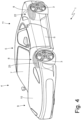
Figure 1 is a perspective view of a car manufactured in accordance with the present invention and in a driving configuration; -
Figure 2 is a schematic plan view of the car ofFigure 1 ; -
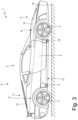
Figure 3 is a side view of the car ofFigure 1 in the driving configuration; -
Figures 4 and5 are respectively a perspective view and a side view of the car ofFigure 1 in a parking configuration; -
Figures 6 and 7 schematically illustrate a detail of the bottom of the car ofFigure 1 respectively in the driving configuration and in the parking configuration; and -
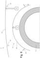
Figures 8 and9 schematically illustrate a detail of a wheel arch and of the body of the car ofFigure 1 respectively in the driving configuration and in the parking configuration. - In
Figure 1 ,reference numeral 1 indicates, as a whole, a car having a rear (or central) engine, said car comprising a chassis 2 (schematically illustrated inFigure 2 ), which supports a pair offront steering wheels 3 and arranged in a front position and a pair ofrear wheels 3 arranged in a rear position at a certain distance (called wheelbase or axle base) from thefront wheels 3; i.e. the wheelbase, also called axle base, indicates the distance between the axis of afront wheel 3 and the axis of therear wheel 3 placed on the same side and is a predominant (major) part of the entire length of thecar 1. The engine (arranged in a rear or central position and schematically illustrated inFigure 2 ) transmits the motion to therear wheels 3 which in this embodiment are steering. - The
chassis 2 is covered by abody 4 which constitutes the external case of thecar 1 and centrally delimits apassenger compartment 5 present between thefront wheels 3 and therear wheels 3. In particular, thebody 4 comprises a pair ofdoors 6 which allow the access to thepassenger compartment 5 and comprises awindshield 7 which frontally delimits thepassenger compartment 5. Inside thepassenger compartment 5, a driver's seat is present equipped with, among other things, a steering wheel (schematically illustrated inFigure 2 ) which allows varying a steering angle of the twofront wheels 3. - Furthermore, the
body 4 is equipped with fourwheel arches 8, each of which surrounds acorresponding wheel 3 at the top. - In front of the passenger compartment 5 a
front compartment 9 is present (for example, but not exclusively, for the luggage) which is closed at the top by a hinged front hood 10 (which is part of the body 4). Behind the passenger compartment 5 arear engine compartment 11 is present (illustrated inFigure 2 ) which is closed at the top by a hinged rear hood 12 (which is part of thebody 4 and is illustrated inFigure 3 ). - According to what illustrated in
Figure 2 , eachfront wheel 3 is mechanically connected to thechassis 2 by means of afront suspension 13 of "multi-link" type (according to a different embodiment thefront suspension 13 is of "articulated quadrilateral" type); analogously, eachrear wheel 3 is mechanically connected to thechassis 2 by means of arear suspension 13 of "multi-link" type. Eachsuspension 13 comprises at least oneactuator device 14 which is controllable for varying the geometry of thesuspension 13 and in particular for modifying the height from the ground of thecar 1, i.e. for modifying the vertical elevation of thewheels 3 with respect to thechassis 2. - According to what illustrated in
Figures 3 and5 , thecar 1 has abottom 15 which inferiorly delimits thecar 1, faces aground 16 on which thecar 1 moves, and is normally shaped for obtaining an aerodynamic effect (for example is flat and is provided in the rear with an extractor which exploits the Venturi effect). - According to what illustrated in
Figures 3 and5 , thechassis 2 is provided inferiorly with a plurality of support feet 17 (in particular foursupport feet 17 arranged between thewheels 3 and in proximity of the wheels 3) which are adapted to rest on theground 16 for supporting the weight of thecar 1. Thesupport feet 17 are movable between a driving position (illustrated inFigure 3 ) in which thesupport feet 17 are flush with the bottom 15 (i.e. a lower surface of eachsupport foot 17 is connected in a seamless manner to the lower surface of the bottom 15) and a parking position (illustrated inFigure 5 ) in which thesupport feet 17 protrude downwards from thebottom 15. In particular, fouractuator devices 18 are provided, each of which is adapted to move, only when thecar 1 is parked, acorresponding support foot 17 between the driving position (illustrated inFigure 3 ) and the parking position (illustrated inFigure 5 ). - According to a possible embodiment illustrated in
Figures 6 and 7 , through the bottom 15 arecess 19 is present which is closed by amovable flap 20 and houses asensor 21 which is adapted to detect a conformation of theground 16 below thebottom 15 for checking the presence of raised parts in the ground 16 (which could damage thebottom 15 in the parking position). Preferably, thesensor 21 is of optical type and comprises a video camera which frames theground 16 below thebottom 15 and is oriented in a direction opposite to the travel direction V; i.e. thesensor 21 is arranged in a front position of thebottom 15 and faces backwards (i.e. towards the tail of the car 1) for framing from the front theground 16 below thebottom 15. The function of themovable flap 20 is to protect thesensor 21 both from dust and water which are raised during the driving (which could dirty the optics preventing thesensor 21 from having a correct vision), and from possible debris which could be raised during the driving (which could damage the sensor 21) . - The
actuator devices 14 are configured to lift, only when thesports car 1 is parked, thewheels 3 upwards with respect to thechassis 2 changing the geometry of thesuspensions 13 up to rest on theground 16 thesupport feet 17 i.e. until thewheels 3 detach from the ground 16 (as illustrated inFigure 5 ). In other words, thesuspensions 13 and theactuator devices 14 are designed to impress on the wheels 3 a sufficiently long vertical travel such to detach thewheels 3 from the ground 16 (obviously only when thecar 1 is parked) resting thecar 1 on theground 16 on the support feet 17 (as illustrated inFigure 5 ). - The
car 1 comprises a control unit 22 (schematically illustrated inFigure 2 ) which is configured to control, only when thecar 1 is parked, theactuator devices 14 so as to lift thewheels 3 upwards with respect to thechassis 2 up to rest on theground 16 thesupport feet 17 i.e. until thewheels 3 detach from theground 16. Obviously, before starting the lifting of thewheels 3 with respect to thechassis 2, thecontrol unit 22 makes thesupport feet 17 come out of the driving position (illustrated inFigure 3 ) to the parking position (illustrated inFigure 5 ). - In particular, the
control unit 22 allows lifting thewheels 3 upwards with respect to thechassis 2 only when theground 16 below thebottom 15 does not have raised parts (the presence of which is checked by the sensor 21). Obviously, before allowing thecar 1 to drive off, thecontrol unit 22 lowers thewheels 3 with respect to thechassis 2 so as to rest thewheels 3 again on theground 16 and thus retracts thesupport feet 17 from the parking position (illustrated inFigure 5 ) to the driving position (illustrated inFigure 3 ). - According to a preferred embodiment, the
control unit 22 allows lifting thewheels 3 upwards with respect to thechassis 2 only when thedoors 6 are closed and instantly locks any lifting/lowering of thewheels 3 with respect to thechassis 2 if adoor 6 is opened. - Resting the
car 1 on the ground by means of the support feet 17 (which have a modest thickness quantifiable for example in 1-2 centimeters) allows remarkably lowering (up to bringing thebottom 15 to come close to the ground 16) the passenger compartment 5 (of course only when thecar 1 is parked); by exploiting a verylow passenger compartment 5 when thecar 1 is parked and consequently by suitably designing the conformation and the hinging of thedoors 6, it is possible to obtain an excellent accessibility to thepassenger compartment 5 both in getting in, and in getting out. - According to a possible embodiment illustrated in
Figures 8 and9 , thebody 4 comprises, in correspondence with thewheels 3 or in correspondence with at least part of the wheels 3 (for example only for thefront wheels 3 or only for the rear wheels 3), movable panels 23 (only one of which is illustrated inFigures 8 and9 ). Each movable panel 23 (which is not structural and thus is not part of the chassis 2) is arranged in correspondence with a single and sole wheel 3 (i.e. involves only one wheel 3), is above the single andsole wheel 3 and is vertically movable with respect to thechassis 2 between a lowered position (illustrated inFigure 8 ) which is always assumed while driving and a raised position (illustrated inFigure 9 ) which is assumed only when thecar 1 is parked for allowing the lifting of thewheel 3 with respect to the chassis 2 (i.e. for creating free space above thewheel 3 and which thewheel 3 occupies during its lifting). - For each
movable panel 23 anactuator device 24 is provided which is adapted to move themovable panel 23 between the lowered position (illustrated inFigure 8 ) and the raised position (illustrated inFigure 9 ). - Preferably, the
body 4 comprises at least one elasticallydeformable portion 25 which connects eachmovable panel 23 to the rest of thebody 4 and elastically deforms to allow themovable panel 23 moving between the lowered position (illustrated inFigure 8 ) and the raised position (illustrated inFigure 9 ). For example, thedeformable portion 25 could be composed of a waterproof fabric and having a suitable surface finishing in the external part (which is fully exposed in the raised position). According to a possible embodiment, eachmovable panel 23 could be partially or completely made of elastically deformable material (i.e. could be devoid of rigid parts). - According to a possible embodiment illustrated in
Figures 8 and9 , thewheel arches 8 or at least part of the wheel arches 8 (for example only thefront wheel arches 8 or only the rear wheel arches 8) comprise respective movable panels 26 (only one of which is illustrated inFigures 8 and9 ). Each movable panel 26 (which is not structural and thus is not part of the chassis 2) is part of awheel arch 8, is arranged below a corresponding movable panel 23 (if present), and is vertically movable with respect to thechassis 2 and synchronized with the corresponding movable panel 23 (if present) between a lowered position (illustrated inFigure 8 ) which is always assumed while driving and a raised position which is assumed only when thecar 1 is parked (illustrated inFigure 8 ). I.e. each movable panel 26 (just as each movable panel 23) is arranged in correspondence with a single and sole wheel 3 (i.e. involves only one wheel 3) and is above the single andsole wheel 3. - For each
movable panel 26 anactuator device 27 is provided which is adapted to move themovable panel 26 between the lowered position (illustrated inFigure 8 ) and the raised position (illustrated inFigure 9 ). In asame wheel 3, theactuator device 27 could have parts in common with the actuator device 24: for example, the twoactuator devices movable panels - The
actuator devices 24 and 27 (which act on themovable panels 23 and 26) are completely separate from and independent of the actuator devices 14 (which act in the suspensions 13) are adapted to move the respectivemovable panels chassis 2 between the lowered position and the raised position with a movement totally autonomous from a movement of thewheels 3 with respect to the chassis 2 (i.e. from an internal movement of the suspensions 13). - Preferably, at least one elastically
deformable portion 28 is provided which connects eachmovable panel 26 to the rest of thewheel arch 8 and elastically deforms to allow themovable panel 26 moving between the lowered position (illustrated inFigure 8 ) and the raised position (illustrated inFigure 9 ). For example, thedeformable portion 28 could be composed of a waterproof fabric. According to a possible embodiment, eachmovable panel 26 could be partially or completely made of elastically deformable material (i.e. could be devoid of rigid parts). - As said in the foregoing, four
movable panels 23 and fourmovable panels 26 could be provided, or two movable panels 23 (in front position or in rear position) and two movable panels 26 (in front position or in rear position), only two or four movable panels 23 (i.e. no movable panel 26), only two or four movable panels 26 (i.e. no movable panel 23), two movable panels 23 (in front position or in rear position) and fourmovable panels 26, or two movable panels 26 (in front position or in rear position) and fourmovable panels 23. Alternatively, themovable panels - The presence, the number and the position of the
movable panels body 4 and of thewheel arches 8 and on the overall vertical travel of thewheels 3 with respect to thechassis 2, i.e. depends on the fact that, in the absence of themovable panels wheels 3 lifting vertically with respect to thechassis 2 beat or do not beat against thewheel arches 8 or against thebody 4. - The embodiments described herein can be combined with each other.
- The
car 1 described above has numerous advantages. - Firstly and as said in the foregoing, by exploiting a very
low passenger compartment 5 when thecar 1 is parked and consequently by suitably designing the conformation and the hinging of thedoors 6, it is possible to obtain an excellent accessibility to thepassenger compartment 5 both in getting in, and in getting out. - Furthermore, when the
car 1 is parked thewheels 3 are lifted off theground 16 and thus are not deformed by the weight of thecar 1 and do not risk ovalizing in case of prolonged stop (in fact it is frequent that a high-performance sports car is relatively not much used and thus remains parked in the same position for a long time). - When the
car 1 is parked thewheels 3 are lifted off theground 16 and thus can be dismounted and remounted easily; a change of tires during the use on track (not infrequent for a high-performance sports car) is thus extremely facilitated not having to lift thecar 1 with external lifts. - Finally, the
car 1 described above is relatively simple and cost-effective to manufacture since thesuspensions 13 having a variable geometry and thecorresponding actuator devices 14 are already present in a high-performance sports car and thus it is necessary to add only the support feet 17 (if there is suitable space between thewheels 8 and the wheel arches 8). -
- 1
- car
- 2
- chassis
- 3
- wheels
- 4
- body
- 5
- passenger compartment
- 6
- doors
- 7
- windshield
- 8
- wheel arch
- 9
- front compartment
- 10
- front hood
- 11
- rear engine compartment
- 12
- rear hood
- 13
- suspension
- 14
- actuator device
- 15
- bottom
- 16
- ground
- 17
- support feet
- 18
- actuator device
- 19
- recess
- 20
- flap
- 21
- sensor
- 22
- control unit
- 23
- movable panel
- 24
- actuator device
- 25
- deformable portion
- 26
- movable panel
- 27
- actuator device
- 28
- deformable portion
- V
- travel direction
Claims (15)
- A high-performance sports car (1) comprising:a chassis (2);a bottom (15) facing a ground (16) on which the sports car (1) moves;two front steering wheels (3) supported by the chassis (2) and arranged in a front position;two rear wheels (3) supported by the chassis (2) and arranged in a rear position at a certain distance from the front wheels (3);an engine which transmits the motion to driving wheels (3) ;a passenger compartment (5) present between the front wheels (3) and the rear wheels (3);a steering wheel which is arranged in the passenger compartment (5) and adjusts a steering angle of the two front steering wheels (3);four suspensions (13), each of which connects a corresponding wheel (3) to the chassis (2), has a variable geometry, and is equipped with at least a first actuator device (14) adapted to modify the geometry of the suspensions (13); anda body (4) which covers the chassis (2) and is equipped with four wheel arches (8), each of which surrounds a corresponding wheel (3) at the top;the sports car (1) is characterized in that:the chassis (2) is provided inferiorly with a plurality of support feet (17) which are adapted to rest on the ground (16) to support the weight of the sports car (1);the first actuator devices (14) are configured to lift, only when the sports car (1) is parked, the wheels (3) upwards with respect to the chassis (2) changing the geometry of the suspensions (13) up to rest on the ground (16) the support feet (17) until the wheels (3) detach from the ground (16);a sensor (21) is provided which is adapted to detect a conformation of the ground (16) below the bottom (15) to check the presence of raised parts in the ground (16); anda control unit (22) is provided which is configured to lift, only when the sports car (1) is parked, the wheels (3) upwards with respect to the chassis (2) only when the ground (16) below the bottom (15) has no raised parts.
- The sports car (1) according to claim 1, wherein the support feet (17) are movable between a driving position in which the support feet (17) are flush with the bottom (15) and a parking position in which the support feet (17) protrude downwards from the bottom (15).
- The sports car (1) according to claim 2 and comprising a plurality of second actuator devices (18), each of which is capable of moving, only when the sports car (1) is parked, a corresponding support foot (17) between the driving position and the parking position.
- The sports car (1) according to claim 1, 2 or 3, wherein the sensor (21) is of the optical type and comprises a video camera which is arranged in a recess (19) present in the bottom (15) and is preferably oriented in a direction opposite to a travel direction (V).
- The sports car (1) according to claim 4, wherein the recess (19) is protected by a normally closed flap (20) which opens only when the sports car (1) is parked.
- The sports car (1) according to any one of the claims from 1 to 5 and comprising:at least a first movable panel (23) which is not structural and thus is not part of the chassis (2), is arranged in correspondence with a single and sole wheel (3), and is vertically movable with respect to the chassis (2) between a lowered position which is always assumed while driving and a raised position which is assumed only when the sports car (1) is parked; andat least a third actuator device which is completely separate from and independent of the first actuator devices (14) and is adapted to move the first movable panel (23) with respect to the chassis (2) between the lowered position and the raised position with a movement totally autonomous from a movement of the wheels (3) with respect to the chassis (2) .
- The sports car (1) according to claim 6, wherein the first movable panel (23) is part of the body (4).
- The sports car (1) according to claim 7 and comprising at least an elastically deformable portion (25) which connects the first movable panel (23) to the rest of the body (4) and elastically deforms to allow the first movable panel (23) moving between the lowered position and the raised position.
- The sports car (1) according to claim 6, wherein the first movable panel (26) is part of a wheel arch (8).
- The sports car (1) according to claim 6, 7 or 8 wherein:the first movable panel (23) is part of the body (4); andat least a second movable panel (26) is provided which is part of a wheel arch (8), is arranged below the first movable panel (23), and is movable vertically and synchronized with the first movable panel (23) between a lowered position which is always assumed while driving and a raised position which is only assumed when the sports car (1) is parked.
- A high-performance sports car (1) comprising:a chassis (2);a bottom (15) facing a ground (16) on which the sports car (1) moves;two front steering wheels (3) supported by the chassis (2) and arranged in a front position;two rear wheels (3) supported by the chassis (2) and arranged in a rear position at a certain distance from the front wheels (3);an engine that transmits the motion to driving wheels (3) ;a passenger compartment (5) present between the front wheels (3) and the rear wheels (3);a steering wheel which is arranged in the passenger compartment (5) and adjusts a steering angle of the two front steering wheels (3);four suspensions (13), each of which connects a corresponding wheel (3) to the chassis (2), has a variable geometry, and is equipped with at least a first actuator device (14) adapted to modify the geometry of the suspensions (13); anda body (4) which covers the chassis (2) and is equipped with four wheel arches (8), each of which surrounds a corresponding wheel (3) at the top;the sports car (1) is characterized in that:the chassis (2) is provided inferiorly with a plurality of support feet (17) which are adapted to rest on the ground (16) to support the weight of the sports car (1);the first actuator devices (14) are configured to lift, only when the sports car (1) is parked, the wheels (3) upwards with respect to the chassis (2) changing the geometry of the suspensions (13) up to rest on the ground (16) the support feet (17 until the wheels (3) detach from the ground (16);at least a first movable panel (23) is provided which is not structural and thus is not part of the chassis (2), is arranged in correspondence with a single and sole wheel (3) and is vertically movable with respect to the chassis (2) between a lowered position which is always assumed while driving and a raised position which is assumed only when the sports car (1) is parked; andat least a second actuator device is provided which is completely separate from and independent of the first actuator devices (14) and is adapted to move the first movable panel (23) with respect to the chassis (2) between the lowered position and the raised position with a movement totally autonomous from a movement of the wheels (3) with respect to the chassis (2).
- The sports car (1) according to claim 11, wherein the first movable panel (23) is part of the body (4).
- The sports car (1) according to claim 12 and comprising at least an elastically deformable portion (25) which connects the first movable panel (23) to the rest of the body (4) and elastically deforms to allow the first movable panel (23) moving between the lowered position and the raised position.
- The sports car (1) according to claim 11, wherein the first movable panel (26) is part of a wheel arch (8).
- The sports car (1) according to claim 11, 12 or 13 wherein:the first movable panel (23) is part of the body (4); andat least a second movable panel (26) is provided which is part of a wheel arch (8), is arranged below the first movable panel (23), and is movable vertically and synchronized with the first movable panel (23) between a lowered position which is always assumed while driving and a raised position which is only assumed when the sports car (1) is parked.
Applications Claiming Priority (2)
| Application Number | Priority Date | Filing Date | Title |
|---|---|---|---|
| IT102020000011707A IT202000011707A1 (en) | 2020-05-20 | 2020-05-20 | HIGH PERFORMANCE SPORTS CAR AND RELATED CONTROL METHOD |
| PCT/IB2021/054384 WO2021234630A1 (en) | 2020-05-20 | 2021-05-20 | High performance sports car and corresponding control method |
Publications (2)
| Publication Number | Publication Date |
|---|---|
| EP3959089A1 EP3959089A1 (en) | 2022-03-02 |
| EP3959089B1 true EP3959089B1 (en) | 2023-06-28 |
Family
ID=71994910
Family Applications (1)
| Application Number | Title | Priority Date | Filing Date |
|---|---|---|---|
| EP21733539.7A Active EP3959089B1 (en) | 2020-05-20 | 2021-05-20 | High performance sports car |
Country Status (6)
| Country | Link |
|---|---|
| US (1) | US11975586B2 (en) |
| EP (1) | EP3959089B1 (en) |
| JP (1) | JP7677907B2 (en) |
| CN (1) | CN114340921B (en) |
| IT (1) | IT202000011707A1 (en) |
| WO (1) | WO2021234630A1 (en) |
Families Citing this family (1)
| Publication number | Priority date | Publication date | Assignee | Title |
|---|---|---|---|---|
| US20230150331A1 (en) * | 2021-11-15 | 2023-05-18 | Sony Group Corporation | Vehicle with suspension-controlled motion resistance members |
Citations (1)
| Publication number | Priority date | Publication date | Assignee | Title |
|---|---|---|---|---|
| US20020100901A1 (en) * | 2001-01-26 | 2002-08-01 | Zac Topelberg | Vehicle lifting system |
Family Cites Families (24)
| Publication number | Priority date | Publication date | Assignee | Title |
|---|---|---|---|---|
| FR1216104A (en) * | 1958-02-26 | 1960-04-22 | Daimler Benz Ag | Automotive car with air elastic suspension |
| GB964964A (en) * | 1963-07-15 | 1964-07-29 | Charles Pitt Barton Stacey Ltd | Improvements in road vehicles |
| JPH0174956U (en) * | 1987-11-09 | 1989-05-22 | ||
| JPH0513885U (en) * | 1991-08-06 | 1993-02-23 | 三菱重工業株式会社 | Movable penders for wheeled vehicles |
| JP2004268902A (en) * | 2003-02-18 | 2004-09-30 | Nissan Motor Co Ltd | Vehicle height adjustment device |
| US6991221B1 (en) * | 2005-04-26 | 2006-01-31 | Rodriguez Daniel G | Automatic jacking system for an automotive vehicle |
| JP4626438B2 (en) * | 2005-08-04 | 2011-02-09 | トヨタ自動車株式会社 | Stack escape support device and stack escape support method |
| JP2009012696A (en) * | 2007-07-09 | 2009-01-22 | Fujitsu Ten Ltd | Vehicle control device, and vehicle control method |
| US8182193B2 (en) * | 2008-10-28 | 2012-05-22 | Max-Atlas | Trailer for transporting freight containers and method of use |
| US8439373B2 (en) * | 2008-11-03 | 2013-05-14 | The Boeing Company | Systems and methods for raising a section of a vehicle off the ground without a jack |
| US8256553B2 (en) * | 2010-02-17 | 2012-09-04 | Roberto De Paschoal | Electric vehicles |
| US20140353948A1 (en) * | 2013-05-31 | 2014-12-04 | Jeffrey J. Hermanson | Vehicle accessibility system |
| FR3014063B1 (en) * | 2013-12-03 | 2017-06-23 | Renault Sas | VEHICLE WITH DEVICE FOR PREVENTING THE SHOCK OF AN UNDERBODY, AND CORRESPONDING PREVENTION METHOD |
| US9126568B1 (en) * | 2014-12-01 | 2015-09-08 | J. Hugh Reid, Jr. | Integrated jacking system |
| US10160278B2 (en) * | 2014-12-16 | 2018-12-25 | Aktv8 LLC | System and method for vehicle stabilization |
| US20160251001A1 (en) * | 2015-02-26 | 2016-09-01 | William King | Vehicle lift system |
| CA3012289C (en) * | 2016-01-27 | 2022-01-25 | EM Solutions Incorporated | System for raising and lowering vehicle |
| DE102016005860B3 (en) * | 2016-05-12 | 2017-04-27 | Audi Ag | Method for operating an active chassis of a motor vehicle |
| US20190009831A1 (en) * | 2017-07-07 | 2019-01-10 | International Business Machines Corporation | Actively deployable and retractable fender skirts for increased fuel efficiency |
| CN107297998A (en) * | 2017-08-05 | 2017-10-27 | 杨家波 | Automotive wheel elevating mechanism, chassis dynamic stabilization system and dynamic stabilization methods |
| US10696115B2 (en) * | 2018-06-22 | 2020-06-30 | Southwest Research Institute | Movement system for an omnidirectional vehicle |
| US20200016951A1 (en) * | 2018-07-10 | 2020-01-16 | Continental Automotive Systems, Inc. | Air suspension leveling based on data available to the vehicle |
| EP3867132A1 (en) * | 2018-10-16 | 2021-08-25 | Michael Traut | Lifting device for the translational progressive movement of a motor vehicle |
| FR3105953B1 (en) * | 2020-01-08 | 2022-01-21 | Commissariat Energie Atomique | VEHICLE COMPRISING A CHASSIS WITH A CONTROLLED VERTICAL POSITION, TO BE LOWERED INTO A LOW POSITION OF SUPPORT ON THE GROUND |
-
2020
- 2020-05-20 IT IT102020000011707A patent/IT202000011707A1/en unknown
-
2021
- 2021-05-20 CN CN202180003722.0A patent/CN114340921B/en active Active
- 2021-05-20 JP JP2021570168A patent/JP7677907B2/en active Active
- 2021-05-20 WO PCT/IB2021/054384 patent/WO2021234630A1/en not_active Ceased
- 2021-05-20 US US17/614,589 patent/US11975586B2/en active Active
- 2021-05-20 EP EP21733539.7A patent/EP3959089B1/en active Active
Patent Citations (1)
| Publication number | Priority date | Publication date | Assignee | Title |
|---|---|---|---|---|
| US20020100901A1 (en) * | 2001-01-26 | 2002-08-01 | Zac Topelberg | Vehicle lifting system |
Also Published As
| Publication number | Publication date |
|---|---|
| CN114340921A (en) | 2022-04-12 |
| EP3959089A1 (en) | 2022-03-02 |
| US11975586B2 (en) | 2024-05-07 |
| JP2023525605A (en) | 2023-06-19 |
| CN114340921B (en) | 2025-03-25 |
| JP7677907B2 (en) | 2025-05-15 |
| WO2021234630A1 (en) | 2021-11-25 |
| US20230079016A1 (en) | 2023-03-16 |
| IT202000011707A1 (en) | 2021-11-20 |
Similar Documents
| Publication | Publication Date | Title |
|---|---|---|
| US6428026B1 (en) | Staggered independent suspension | |
| US4904015A (en) | Air deflection system | |
| US8864153B2 (en) | Automotive rear suspension subassembly | |
| AU2018308943B2 (en) | Towable vehicle | |
| US8556322B2 (en) | Vehicle with a panel that is moveable to provide increased head room above a rear row of seats | |
| US8419120B2 (en) | Vehicle with a panel that is moveable to provide increased head room above a rear row of seats | |
| US9975463B2 (en) | Lowering suspension | |
| EP3959089B1 (en) | High performance sports car | |
| US3820809A (en) | Body tilting mechanism | |
| CN106347460B (en) | A kind of flexible carriage frame | |
| RU2487029C2 (en) | Transport block with orientation device for automobile | |
| CN117698863A (en) | Method for coupling a tractor to a semi-trailer and semi-trailer comprising same | |
| US10384523B2 (en) | Convertible top having link arrangements for adjusting a convertible-top element | |
| EP1561674B1 (en) | Adjustable-wheelbase vehicle chassis | |
| US20240190520A1 (en) | Vehicle with a gap between the chassis and the cab closed by a sealing device | |
| CN203439193U (en) | Electric carrier tricycle | |
| CN109968929B (en) | Vehicle connecting bridges, trackless vehicles and trackless trains | |
| CN116691228B (en) | Follow-up steering lifting bridge assembly and vehicle chassis | |
| CN211195791U (en) | Windshield and vehicle comprising same | |
| US12195111B2 (en) | Robotized tractor unit | |
| KR102944150B1 (en) | Side mirrors for large vehicles | |
| JP2542662Y2 (en) | Vehicle carrier | |
| CN110525173A (en) | A kind of windscreen and the vehicle including the windscreen | |
| GB2640593A (en) | Vehicle door assembly with single A post | |
| CN116332084A (en) | A front and rear axle balance adjustment mechanism |
Legal Events
| Date | Code | Title | Description |
|---|---|---|---|
| STAA | Information on the status of an ep patent application or granted ep patent |
Free format text: STATUS: UNKNOWN |
|
| STAA | Information on the status of an ep patent application or granted ep patent |
Free format text: STATUS: THE INTERNATIONAL PUBLICATION HAS BEEN MADE |
|
| PUAI | Public reference made under article 153(3) epc to a published international application that has entered the european phase |
Free format text: ORIGINAL CODE: 0009012 |
|
| STAA | Information on the status of an ep patent application or granted ep patent |
Free format text: STATUS: REQUEST FOR EXAMINATION WAS MADE |
|
| 17P | Request for examination filed |
Effective date: 20211126 |
|
| AK | Designated contracting states |
Kind code of ref document: A1 Designated state(s): AL AT BE BG CH CY CZ DE DK EE ES FI FR GB GR HR HU IE IS IT LI LT LU LV MC MK MT NL NO PL PT RO RS SE SI SK SM TR |
|
| GRAP | Despatch of communication of intention to grant a patent |
Free format text: ORIGINAL CODE: EPIDOSNIGR1 |
|
| STAA | Information on the status of an ep patent application or granted ep patent |
Free format text: STATUS: GRANT OF PATENT IS INTENDED |
|
| INTG | Intention to grant announced |
Effective date: 20230116 |
|
| GRAS | Grant fee paid |
Free format text: ORIGINAL CODE: EPIDOSNIGR3 |
|
| GRAA | (expected) grant |
Free format text: ORIGINAL CODE: 0009210 |
|
| STAA | Information on the status of an ep patent application or granted ep patent |
Free format text: STATUS: THE PATENT HAS BEEN GRANTED |
|
| AK | Designated contracting states |
Kind code of ref document: B1 Designated state(s): AL AT BE BG CH CY CZ DE DK EE ES FI FR GB GR HR HU IE IS IT LI LT LU LV MC MK MT NL NO PL PT RO RS SE SI SK SM TR |
|
| DAV | Request for validation of the european patent (deleted) | ||
| DAX | Request for extension of the european patent (deleted) | ||
| REG | Reference to a national code |
Ref country code: CH Ref legal event code: EP |
|
| P01 | Opt-out of the competence of the unified patent court (upc) registered |
Effective date: 20230525 |
|
| REG | Reference to a national code |
Ref country code: AT Ref legal event code: REF Ref document number: 1582409 Country of ref document: AT Kind code of ref document: T Effective date: 20230715 |
|
| REG | Reference to a national code |
Ref country code: IE Ref legal event code: FG4D |
|
| REG | Reference to a national code |
Ref country code: DE Ref legal event code: R096 Ref document number: 602021003168 Country of ref document: DE |
|
| REG | Reference to a national code |
Ref country code: LT Ref legal event code: MG9D |
|
| PG25 | Lapsed in a contracting state [announced via postgrant information from national office to epo] |
Ref country code: SE Free format text: LAPSE BECAUSE OF FAILURE TO SUBMIT A TRANSLATION OF THE DESCRIPTION OR TO PAY THE FEE WITHIN THE PRESCRIBED TIME-LIMIT Effective date: 20230628 Ref country code: NO Free format text: LAPSE BECAUSE OF FAILURE TO SUBMIT A TRANSLATION OF THE DESCRIPTION OR TO PAY THE FEE WITHIN THE PRESCRIBED TIME-LIMIT Effective date: 20230928 |
|
| REG | Reference to a national code |
Ref country code: NL Ref legal event code: MP Effective date: 20230628 |
|
| REG | Reference to a national code |
Ref country code: AT Ref legal event code: MK05 Ref document number: 1582409 Country of ref document: AT Kind code of ref document: T Effective date: 20230628 |
|
| PG25 | Lapsed in a contracting state [announced via postgrant information from national office to epo] |
Ref country code: RS Free format text: LAPSE BECAUSE OF FAILURE TO SUBMIT A TRANSLATION OF THE DESCRIPTION OR TO PAY THE FEE WITHIN THE PRESCRIBED TIME-LIMIT Effective date: 20230628 Ref country code: NL Free format text: LAPSE BECAUSE OF FAILURE TO SUBMIT A TRANSLATION OF THE DESCRIPTION OR TO PAY THE FEE WITHIN THE PRESCRIBED TIME-LIMIT Effective date: 20230628 Ref country code: LV Free format text: LAPSE BECAUSE OF FAILURE TO SUBMIT A TRANSLATION OF THE DESCRIPTION OR TO PAY THE FEE WITHIN THE PRESCRIBED TIME-LIMIT Effective date: 20230628 Ref country code: LT Free format text: LAPSE BECAUSE OF FAILURE TO SUBMIT A TRANSLATION OF THE DESCRIPTION OR TO PAY THE FEE WITHIN THE PRESCRIBED TIME-LIMIT Effective date: 20230628 Ref country code: HR Free format text: LAPSE BECAUSE OF FAILURE TO SUBMIT A TRANSLATION OF THE DESCRIPTION OR TO PAY THE FEE WITHIN THE PRESCRIBED TIME-LIMIT Effective date: 20230628 Ref country code: GR Free format text: LAPSE BECAUSE OF FAILURE TO SUBMIT A TRANSLATION OF THE DESCRIPTION OR TO PAY THE FEE WITHIN THE PRESCRIBED TIME-LIMIT Effective date: 20230929 |
|
| PG25 | Lapsed in a contracting state [announced via postgrant information from national office to epo] |
Ref country code: FI Free format text: LAPSE BECAUSE OF FAILURE TO SUBMIT A TRANSLATION OF THE DESCRIPTION OR TO PAY THE FEE WITHIN THE PRESCRIBED TIME-LIMIT Effective date: 20230628 |
|
| PG25 | Lapsed in a contracting state [announced via postgrant information from national office to epo] |
Ref country code: SK Free format text: LAPSE BECAUSE OF FAILURE TO SUBMIT A TRANSLATION OF THE DESCRIPTION OR TO PAY THE FEE WITHIN THE PRESCRIBED TIME-LIMIT Effective date: 20230628 |
|
| PG25 | Lapsed in a contracting state [announced via postgrant information from national office to epo] |
Ref country code: ES Free format text: LAPSE BECAUSE OF FAILURE TO SUBMIT A TRANSLATION OF THE DESCRIPTION OR TO PAY THE FEE WITHIN THE PRESCRIBED TIME-LIMIT Effective date: 20230628 |
|
| PG25 | Lapsed in a contracting state [announced via postgrant information from national office to epo] |
Ref country code: IS Free format text: LAPSE BECAUSE OF FAILURE TO SUBMIT A TRANSLATION OF THE DESCRIPTION OR TO PAY THE FEE WITHIN THE PRESCRIBED TIME-LIMIT Effective date: 20231028 |
|
| PG25 | Lapsed in a contracting state [announced via postgrant information from national office to epo] |
Ref country code: SM Free format text: LAPSE BECAUSE OF FAILURE TO SUBMIT A TRANSLATION OF THE DESCRIPTION OR TO PAY THE FEE WITHIN THE PRESCRIBED TIME-LIMIT Effective date: 20230628 Ref country code: SK Free format text: LAPSE BECAUSE OF FAILURE TO SUBMIT A TRANSLATION OF THE DESCRIPTION OR TO PAY THE FEE WITHIN THE PRESCRIBED TIME-LIMIT Effective date: 20230628 Ref country code: RO Free format text: LAPSE BECAUSE OF FAILURE TO SUBMIT A TRANSLATION OF THE DESCRIPTION OR TO PAY THE FEE WITHIN THE PRESCRIBED TIME-LIMIT Effective date: 20230628 Ref country code: PT Free format text: LAPSE BECAUSE OF FAILURE TO SUBMIT A TRANSLATION OF THE DESCRIPTION OR TO PAY THE FEE WITHIN THE PRESCRIBED TIME-LIMIT Effective date: 20231030 Ref country code: IS Free format text: LAPSE BECAUSE OF FAILURE TO SUBMIT A TRANSLATION OF THE DESCRIPTION OR TO PAY THE FEE WITHIN THE PRESCRIBED TIME-LIMIT Effective date: 20231028 Ref country code: ES Free format text: LAPSE BECAUSE OF FAILURE TO SUBMIT A TRANSLATION OF THE DESCRIPTION OR TO PAY THE FEE WITHIN THE PRESCRIBED TIME-LIMIT Effective date: 20230628 Ref country code: EE Free format text: LAPSE BECAUSE OF FAILURE TO SUBMIT A TRANSLATION OF THE DESCRIPTION OR TO PAY THE FEE WITHIN THE PRESCRIBED TIME-LIMIT Effective date: 20230628 Ref country code: CZ Free format text: LAPSE BECAUSE OF FAILURE TO SUBMIT A TRANSLATION OF THE DESCRIPTION OR TO PAY THE FEE WITHIN THE PRESCRIBED TIME-LIMIT Effective date: 20230628 Ref country code: AT Free format text: LAPSE BECAUSE OF FAILURE TO SUBMIT A TRANSLATION OF THE DESCRIPTION OR TO PAY THE FEE WITHIN THE PRESCRIBED TIME-LIMIT Effective date: 20230628 |
|
| PG25 | Lapsed in a contracting state [announced via postgrant information from national office to epo] |
Ref country code: PL Free format text: LAPSE BECAUSE OF FAILURE TO SUBMIT A TRANSLATION OF THE DESCRIPTION OR TO PAY THE FEE WITHIN THE PRESCRIBED TIME-LIMIT Effective date: 20230628 |
|
| REG | Reference to a national code |
Ref country code: DE Ref legal event code: R097 Ref document number: 602021003168 Country of ref document: DE |
|
| PG25 | Lapsed in a contracting state [announced via postgrant information from national office to epo] |
Ref country code: DK Free format text: LAPSE BECAUSE OF FAILURE TO SUBMIT A TRANSLATION OF THE DESCRIPTION OR TO PAY THE FEE WITHIN THE PRESCRIBED TIME-LIMIT Effective date: 20230628 |
|
| PLBE | No opposition filed within time limit |
Free format text: ORIGINAL CODE: 0009261 |
|
| STAA | Information on the status of an ep patent application or granted ep patent |
Free format text: STATUS: NO OPPOSITION FILED WITHIN TIME LIMIT |
|
| 26N | No opposition filed |
Effective date: 20240402 |
|
| PG25 | Lapsed in a contracting state [announced via postgrant information from national office to epo] |
Ref country code: SI Free format text: LAPSE BECAUSE OF FAILURE TO SUBMIT A TRANSLATION OF THE DESCRIPTION OR TO PAY THE FEE WITHIN THE PRESCRIBED TIME-LIMIT Effective date: 20230628 |
|
| PG25 | Lapsed in a contracting state [announced via postgrant information from national office to epo] |
Ref country code: BG Free format text: LAPSE BECAUSE OF FAILURE TO SUBMIT A TRANSLATION OF THE DESCRIPTION OR TO PAY THE FEE WITHIN THE PRESCRIBED TIME-LIMIT Effective date: 20230628 |
|
| PG25 | Lapsed in a contracting state [announced via postgrant information from national office to epo] |
Ref country code: BG Free format text: LAPSE BECAUSE OF FAILURE TO SUBMIT A TRANSLATION OF THE DESCRIPTION OR TO PAY THE FEE WITHIN THE PRESCRIBED TIME-LIMIT Effective date: 20230628 |
|
| REG | Reference to a national code |
Ref country code: CH Ref legal event code: PL |
|
| PG25 | Lapsed in a contracting state [announced via postgrant information from national office to epo] |
Ref country code: MC Free format text: LAPSE BECAUSE OF FAILURE TO SUBMIT A TRANSLATION OF THE DESCRIPTION OR TO PAY THE FEE WITHIN THE PRESCRIBED TIME-LIMIT Effective date: 20230628 |
|
| PG25 | Lapsed in a contracting state [announced via postgrant information from national office to epo] |
Ref country code: LU Free format text: LAPSE BECAUSE OF NON-PAYMENT OF DUE FEES Effective date: 20240520 |
|
| PG25 | Lapsed in a contracting state [announced via postgrant information from national office to epo] |
Ref country code: MC Free format text: LAPSE BECAUSE OF FAILURE TO SUBMIT A TRANSLATION OF THE DESCRIPTION OR TO PAY THE FEE WITHIN THE PRESCRIBED TIME-LIMIT Effective date: 20230628 Ref country code: LU Free format text: LAPSE BECAUSE OF NON-PAYMENT OF DUE FEES Effective date: 20240520 Ref country code: CH Free format text: LAPSE BECAUSE OF NON-PAYMENT OF DUE FEES Effective date: 20240531 |
|
| REG | Reference to a national code |
Ref country code: BE Ref legal event code: MM Effective date: 20240531 |
|
| PG25 | Lapsed in a contracting state [announced via postgrant information from national office to epo] |
Ref country code: IE Free format text: LAPSE BECAUSE OF NON-PAYMENT OF DUE FEES Effective date: 20240520 |
|
| PG25 | Lapsed in a contracting state [announced via postgrant information from national office to epo] |
Ref country code: BE Free format text: LAPSE BECAUSE OF NON-PAYMENT OF DUE FEES Effective date: 20240531 |
|
| PGFP | Annual fee paid to national office [announced via postgrant information from national office to epo] |
Ref country code: DE Payment date: 20250528 Year of fee payment: 5 |
|
| PGFP | Annual fee paid to national office [announced via postgrant information from national office to epo] |
Ref country code: IT Payment date: 20250509 Year of fee payment: 5 |
|
| PGFP | Annual fee paid to national office [announced via postgrant information from national office to epo] |
Ref country code: FR Payment date: 20250526 Year of fee payment: 5 |
|
| PG25 | Lapsed in a contracting state [announced via postgrant information from national office to epo] |
Ref country code: CY Free format text: LAPSE BECAUSE OF FAILURE TO SUBMIT A TRANSLATION OF THE DESCRIPTION OR TO PAY THE FEE WITHIN THE PRESCRIBED TIME-LIMIT; INVALID AB INITIO Effective date: 20210520 |
|
| PG25 | Lapsed in a contracting state [announced via postgrant information from national office to epo] |
Ref country code: HU Free format text: LAPSE BECAUSE OF FAILURE TO SUBMIT A TRANSLATION OF THE DESCRIPTION OR TO PAY THE FEE WITHIN THE PRESCRIBED TIME-LIMIT; INVALID AB INITIO Effective date: 20210520 |
|
| PGFP | Annual fee paid to national office [announced via postgrant information from national office to epo] |
Ref country code: GB Payment date: 20260304 Year of fee payment: 6 |