EP3958770B1 - Chirurgisches instrument - Google Patents
Chirurgisches instrument Download PDFInfo
- Publication number
- EP3958770B1 EP3958770B1 EP20794016.4A EP20794016A EP3958770B1 EP 3958770 B1 EP3958770 B1 EP 3958770B1 EP 20794016 A EP20794016 A EP 20794016A EP 3958770 B1 EP3958770 B1 EP 3958770B1
- Authority
- EP
- European Patent Office
- Prior art keywords
- retention
- surgical instrument
- spinal implant
- drive
- surgical
- Prior art date
- Legal status (The legal status is an assumption and is not a legal conclusion. Google has not performed a legal analysis and makes no representation as to the accuracy of the status listed.)
- Active
Links
Images


Classifications
-
- A—HUMAN NECESSITIES
- A61—MEDICAL OR VETERINARY SCIENCE; HYGIENE
- A61B—DIAGNOSIS; SURGERY; IDENTIFICATION
- A61B17/00—Surgical instruments, devices or methods
- A61B17/56—Surgical instruments or methods for treatment of bones or joints; Devices specially adapted therefor
- A61B17/58—Surgical instruments or methods for treatment of bones or joints; Devices specially adapted therefor for osteosynthesis, e.g. bone plates, screws or setting implements
- A61B17/68—Internal fixation devices, including fasteners and spinal fixators, even if a part thereof projects from the skin
- A61B17/70—Spinal positioners or stabilisers, e.g. stabilisers comprising fluid filler in an implant
- A61B17/7074—Tools specially adapted for spinal fixation operations other than for bone removal or filler handling
- A61B17/7076—Tools specially adapted for spinal fixation operations other than for bone removal or filler handling for driving, positioning or assembling spinal clamps or bone anchors specially adapted for spinal fixation
- A61B17/7082—Tools specially adapted for spinal fixation operations other than for bone removal or filler handling for driving, positioning or assembling spinal clamps or bone anchors specially adapted for spinal fixation for driving, i.e. rotating, screws or screw parts specially adapted for spinal fixation, e.g. for driving polyaxial or tulip-headed screws
-
- A—HUMAN NECESSITIES
- A61—MEDICAL OR VETERINARY SCIENCE; HYGIENE
- A61B—DIAGNOSIS; SURGERY; IDENTIFICATION
- A61B17/00—Surgical instruments, devices or methods
- A61B17/56—Surgical instruments or methods for treatment of bones or joints; Devices specially adapted therefor
- A61B17/58—Surgical instruments or methods for treatment of bones or joints; Devices specially adapted therefor for osteosynthesis, e.g. bone plates, screws or setting implements
- A61B17/68—Internal fixation devices, including fasteners and spinal fixators, even if a part thereof projects from the skin
- A61B17/70—Spinal positioners or stabilisers, e.g. stabilisers comprising fluid filler in an implant
- A61B17/7001—Screws or hooks combined with longitudinal elements which do not contact vertebrae
-
- A—HUMAN NECESSITIES
- A61—MEDICAL OR VETERINARY SCIENCE; HYGIENE
- A61B—DIAGNOSIS; SURGERY; IDENTIFICATION
- A61B17/00—Surgical instruments, devices or methods
- A61B17/56—Surgical instruments or methods for treatment of bones or joints; Devices specially adapted therefor
- A61B17/58—Surgical instruments or methods for treatment of bones or joints; Devices specially adapted therefor for osteosynthesis, e.g. bone plates, screws or setting implements
- A61B17/68—Internal fixation devices, including fasteners and spinal fixators, even if a part thereof projects from the skin
- A61B17/84—Fasteners therefor or fasteners being internal fixation devices
- A61B17/86—Pins or screws or threaded wires; nuts therefor
- A61B17/8605—Heads, i.e. proximal ends projecting from bone
- A61B17/861—Heads, i.e. proximal ends projecting from bone specially shaped for gripping driver
- A61B17/8615—Heads, i.e. proximal ends projecting from bone specially shaped for gripping driver at the central region of the screw head
-
- A—HUMAN NECESSITIES
- A61—MEDICAL OR VETERINARY SCIENCE; HYGIENE
- A61B—DIAGNOSIS; SURGERY; IDENTIFICATION
- A61B17/00—Surgical instruments, devices or methods
- A61B17/56—Surgical instruments or methods for treatment of bones or joints; Devices specially adapted therefor
- A61B17/58—Surgical instruments or methods for treatment of bones or joints; Devices specially adapted therefor for osteosynthesis, e.g. bone plates, screws or setting implements
- A61B17/88—Osteosynthesis instruments; Methods or means for implanting or extracting internal or external fixation devices
- A61B17/8875—Screwdrivers, spanners or wrenches
- A61B17/8877—Screwdrivers, spanners or wrenches characterised by the cross-section of the driver bit
- A61B17/888—Screwdrivers, spanners or wrenches characterised by the cross-section of the driver bit the driver bit acting on the central region of the screw head
-
- A—HUMAN NECESSITIES
- A61—MEDICAL OR VETERINARY SCIENCE; HYGIENE
- A61B—DIAGNOSIS; SURGERY; IDENTIFICATION
- A61B17/00—Surgical instruments, devices or methods
- A61B17/56—Surgical instruments or methods for treatment of bones or joints; Devices specially adapted therefor
- A61B17/58—Surgical instruments or methods for treatment of bones or joints; Devices specially adapted therefor for osteosynthesis, e.g. bone plates, screws or setting implements
- A61B17/88—Osteosynthesis instruments; Methods or means for implanting or extracting internal or external fixation devices
- A61B17/8875—Screwdrivers, spanners or wrenches
- A61B17/8886—Screwdrivers, spanners or wrenches holding the screw head
- A61B17/8888—Screwdrivers, spanners or wrenches holding the screw head at its central region
-
- A—HUMAN NECESSITIES
- A61—MEDICAL OR VETERINARY SCIENCE; HYGIENE
- A61B—DIAGNOSIS; SURGERY; IDENTIFICATION
- A61B17/00—Surgical instruments, devices or methods
- A61B2017/0046—Surgical instruments, devices or methods with a releasable handle; with handle and operating part separable
- A61B2017/00464—Surgical instruments, devices or methods with a releasable handle; with handle and operating part separable for use with different instruments
Definitions
- the present disclosure generally relates to medical devices for the treatment of musculoskeletal disorders, and more particularly to a spinal implant and a surgical system for delivering and/or fastening implants with a surgical site.
- Spinal pathologies and disorders such as scoliosis and other curvature abnormalities, kyphosis, degenerative disc disease, disc herniation, osteoporosis, spondylolisthesis, stenosis, tumor, and fracture may result from factors including trauma, disease and degenerative conditions caused by injury and aging.
- Spinal disorders typically result in symptoms including deformity, pain, nerve damage, and partial or complete loss of mobility.
- Non-surgical treatments such as medication, rehabilitation and exercise can be effective, however, may fail to relieve the symptoms associated with these disorders.
- Surgical treatment of these spinal disorders includes correction, fusion, fixation, discectomy, laminectomy and implantable prosthetics.
- spinal constructs such as vertebral rods are often used to provide stability to a treated region. Rods redirect stresses away from a damaged or defective region while healing takes place to restore proper alignment and generally support the vertebral members.
- one or more rods and bone fasteners can be delivered to a surgical site. The rods may be attached via the fasteners to the exterior of two or more vertebral members.
- Surgical instruments are employed, for example, to engage the fasteners for attachment to the exterior of two or more vertebral members. This disclosure describes an improvement over these prior technologies.
- a spinal implant comprising: a distal portion configured for penetrating tissue and a proximal portion including a socket defining recesses each including a drive surface.
- the present invention provides a spinal implant with the features according to claim 1 and a surgical system with the features according to claim 8. Further preferred embodiments of the spinal implant are described in the dependent claims.
- the exemplary embodiments of a spinal implant and a surgical system are discussed in terms of medical devices for the treatment of musculoskeletal disorders and more particularly, in terms of a surgical system for delivering and/or fastening implants with a surgical site and a method for treating a spine.
- the surgical methods described in the following as well as the embodiment of Figs. 10-13 do not form part of the invention but are helpful in understanding the invention.
- the surgical system includes a surgical instrument, such as, for example, an implant driver and a spinal implant, such as, for example, a bone screw
- the surgical system includes a surgical instrument including a drive surface and a retention surface.
- the surgical system includes a spinal implant including a drive surface and a retention surface.
- the retention surfaces of the spinal implant is tapered, and the retention surfaces are engageable to define a retention interface.
- the retention surface of the surgical instrument is cylindrical, and the retention surfaces are engageable to define a retention interface. In some embodiments, rotational engagement is facilitated due to the retention surfaces holding the surgical instrument axially independently of the drive geometry.
- the spinal implant includes a distal portion configured for penetrating tissue.
- the spinal implant includes proximal portion having a drive surface, a guide surface and a retention surface. The surfaces are disposed in a serial configuration.
- the retention surface is engageable with a surface of a surgical instrument to define a retention interface.
- the surgical system may be employed to treat spinal disorders such as, for example, degenerative disc disease, disc herniation, osteoporosis, spondylolisthesis, stenosis, scoliosis and other curvature abnormalities, kyphosis, tumor and fractures.
- spinal disorders such as, for example, degenerative disc disease, disc herniation, osteoporosis, spondylolisthesis, stenosis, scoliosis and other curvature abnormalities, kyphosis, tumor and fractures.
- the surgical system may be employed with other osteal and bone related applications, including those associated with diagnostics and therapeutics.
- the surgical system may be alternatively employed in a surgical treatment with a patient in a prone or supine position, and/or employ various surgical approaches to the spine, including anterior, posterior, posterior mid-line, lateral, postero-lateral, and/or antero-lateral approaches, and in other body regions.
- the surgical system may also be alternatively employed with procedures for treating the lumbar, cervical, thoracic, sacral and pelvic regions of a spinal column.
- the surgical system of the present disclosure may also be used on animals, bone models and other non-living substrates, such as, for example, in training, testing and demonstration.
- Ranges may be expressed herein as from “about” or “approximately” one particular value and/or to “about” or “approximately” another particular value. When such a range is expressed, another embodiment includes from the one particular value and/or to the other particular value. Similarly, when values are expressed as approximations, by use of the antecedent "about,” it will be understood that the particular value forms another embodiment. It is also understood that all spatial references, such as, for example, horizontal, vertical, top, upper, lower, bottom, left and right, are for illustrative purposes only and can be varied within the scope of the disclosure. For example, the references “upper” and “lower” are relative and used only in the context to the other, and are not necessarily “superior” and “inferior”.
- treating or “treatment” of a disease or condition refers to performing a procedure that may include administering one or more drugs to a patient (human, normal or otherwise or other mammal), employing implantable devices, and/or employing instruments that treat the disease, such as, for example, microdiscectomy instruments used to remove portions bulging or herniated discs and/or bone spurs, in an effort to alleviate signs or symptoms of the disease or condition. Alleviation can occur prior to signs or symptoms of the disease or condition appearing, as well as after their appearance.
- treating or treatment includes preventing or prevention of disease or undesirable condition (e.g., preventing the disease from occurring in a patient, who may be predisposed to the disease but has not yet been diagnosed as having it).
- treating or treatment does not require complete alleviation of signs or symptoms, does not require a cure, and specifically includes procedures that have only a marginal effect on the patient.
- Treatment can include inhibiting the disease, e.g., arresting its development, or relieving the disease, e.g., causing regression of the disease.
- treatment can include reducing acute or chronic inflammation; alleviating pain and mitigating and inducing re-growth of new ligament, bone and other tissues; as an adjunct in surgery; and/or any repair procedure.
- tissue includes soft tissue, ligaments, tendons, cartilage and/or bone unless specifically referred to otherwise.
- FIGS. 1-7 there are illustrated components of a surgical system 10.
- the components of surgical system 10 can be fabricated from biologically acceptable materials suitable for medical applications, including metals, synthetic polymers, ceramics and bone material and/or their composites.
- the components of surgical system 10 individually or collectively, can be fabricated from materials such as stainless steel alloys, commercially pure titanium, titanium alloys, Grade 5 titanium, super-elastic titanium alloys, cobalt-chrome alloys, stainless steel alloys, superelastic metallic alloys (e.g., Nitinol, super elasto-plastic metals, such as GUM METAL ® ), ceramics and composites thereof such as calcium phosphate (e.g., SKELITE TM ), thermoplastics such as polyaryletherketone (PAEK) including polyetheretherketone (PEEK), polyetherketoneketone (PEKK) and polyetherketone (PEK), carbon-PEEK composites, PEEK-BaSO 4 polymeric rubbers, polyethylene terephthalate (PET), fabric, silicone, polyurethane,
- Various components of surgical system 10 may have material composites, including the above materials, to achieve various desired characteristics such as strength, rigidity, elasticity, compliance, biomechanical performance, durability and radiolucency or imaging preference.
- the components of surgical system 10, individually or collectively, may also be fabricated from a heterogeneous material such as a combination of two or more of the above-described materials.
- the components of surgical system 10 may be monolithically formed, integrally connected or include fastening elements and/or instruments, as described herein.
- Surgical system 10 includes a surgical instrument, such as, for example, a driver 12 engageable with a spinal implant, such as, for example, a bone screw 14, as shown in FIGS. 1-4 .
- driver 12 may be utilized with other devices, such as, for example, set screws and/or interbody cages.
- Driver 12 includes a member, such as, for example, an elongated shaft 16.
- Shaft 16 extends between an end, such as, for example, a proximal end 18 and an end, such as, for example, a distal end 20.
- Shaft 16 has a cylindrical cross sectional configuration between ends 18, 20 and includes a diameter D1.
- a portion of shaft 16 may have alternate cross section configurations, such as, for example, oval, oblong, triangular, square, polygonal, irregular, uniform, non-uniform, offset, staggered, and/or tapered.
- Shaft 16 defines a longitudinal axis X1.
- end 18 is configured for engagement and connection with a handle 21, which is configured to facilitate manipulation of driver 12.
- the handle may be disposed at alternate orientations relative to shaft 16, such as, for example, transverse, perpendicular and/or other angular orientations such as acute or obtuse.
- end 18 is configured for engagement and connection with an adaptor, extension and/or other connection to facilitate manipulation of driver 12.
- end 18 includes a tool engagement surface (not shown) configured to engage an actuator, such as, for example, a surgical instrument and/or hand drill to rotate end 20 in a first direction and/or an opposing second direction, such as, for example, clockwise and counter-clockwise directions.
- end 18 may include an interchangeable driving handle removably connected to end 18 such that torque applied manually or by a motorized actuator to the handle is transmitted to shaft 16.
- end 18 is configured to engage an actuator, such as, for example, a motorized actuator, such as, for example, a powered drill (not shown).
- the motorized actuator includes a mating connector, such as, for example, a chuck.
- the chuck includes a socket that is configured to mate with end 18.
- the motorized actuator includes an electric motor, such as, for example, an electric drill motor that is connected to a power source, such as, for example, a battery and/or AC source, for rotating end 20.
- the motorized actuator may be pneumatic or hydraulic.
- End 20 includes an engagement portion 22.
- Portion 22 is configured for engagement with bone screw 14, as described herein.
- Portion 22 includes a drive portion 24 and a retention portion 26.
- Portions 24, 26 are disposed in a serial configuration along axis X1, as shown in FIG. 2 .
- Portion 24 includes a plurality of spaced apart lobes 32 disposed circumferentially about portion 26, as shown in FIG. 1 .
- Lobes 32 includes a hexalobe configuration.
- Portion 24 may have alternate configurations, such as, for example, thread form, triangular, square, polygonal, star, torx, irregular, uniform, non-uniform, offset, staggered, and/or tapered.
- Each lobe 32 includes a drive surface 34 and a trailing surface 36 that is spaced apart from drive surface 34.
- all or a portion of lobe 32 may include various configurations and/or be disposed in various orientations, such as, for example, angular, arcuate, undulating, series, parallel, offset and/or staggered.
- Drive surface 34 is configured to contact a portion of a socket 66 of bone screw 14, as described herein, at a drive interface 38 to drive, torque, insert or otherwise rotate bone screw 14.
- Portion 24 includes a distal face 40.
- Distal face 40 includes a flat or even surface.
- distal face 40 may have various surface configurations, such as, for example, rough, threaded, arcuate, undulating, porous, semi-porous, dimpled, polished and/or textured.
- Portion 26 includes an extension 42 extending from distal face 40.
- extension 42 is monolithically formed with distal face 40.
- extension 42 is integrally connected with distal face 40.
- extension 42 is attachable with distal face 40 with fastening elements and/or instruments.
- Extension 42 includes a cylindrical cross-sectional configuration, as shown in FIG. 2 . some embodiments, all or only a portion of extension 42 may have alternate cross section configurations, such as, for example, oval, oblong, triangular, square, polygonal, irregular, uniform, non-uniform, offset, staggered, and/or tapered.
- Extension 42 includes a diameter D2. Diameter D2 is less than diameter D1. Extension 42 includes a surface 44 that facilitates engaging and retaining of driver 12 with bone screw 14. Surface 44 is configured to contact a portion of bone screw 14 at a retention interface 46, as described herein.
- Retention interface 46 provides for a connection between extension 42 and bone screw 14 that is independent of the geometry of driver 12 and socket 66. For example, as bone screw 14 is driven into the bone, slight distortions occur under a normal driving force, retention interface 46 resists and/or prevents driver 12 from disengaging from bone screw 14 unexpectedly. In some embodiments, retention interface 46 is configured to cause wear on a surface of bone screw 14 rather than driver 12 providing for a more durable connection. Retention interface 46 is configured to resist and/or prevent stripping of socket 66 by distributing the torque load across drive interface 38 and retention interface 46. In some embodiments, retention interface 46 provides a configuration that resists and/or prevents toggle between driver 12 and bone screw 14.
- Bone screw 14 extends along an axis X2, as shown in FIG. 4 .
- Bone screw 14 shown in Fig. 3 includes a distal portion 58 and a proximal portion 60.
- Distal portion 58 includes a shaft 62 configured to penetrate tissue, such as, for example, bone.
- Shaft 62 includes a thread form on an outer surface thereof. In some embodiments, the thread form may extend such that shaft 62 is threaded along the entire length thereof. In some embodiments, all or only a portion of shaft 62 may have various surface configurations, such as, for example, rough, threaded, arcuate, undulating, porous, semi-porous, dimpled, polished and/or textured.
- Proximal portion 60 includes a socket 66.
- Socket 66 defines recesses 76 configured for disposal of lobes 32.
- recesses 76 includes a hexalobe configuration.
- recesses 76 may have alternate configurations, such as, for example, thread form, triangular, square, polygonal, star, torx, irregular, uniform, non-uniform, offset, staggered, and/or tapered.
- Each recess 76 includes a drive surface 68 configured for engagement with drive surface 34 at drive interface 38, as shown in FIG. 5 , causing drive surface 34 to drive, torque, insert or otherwise rotate bone screw 14 by applying a force to drive surface 68.
- Cavity 80 defines a cavity 80 configured for disposal of extension 42.
- Cavity 80 includes a tapered configuration, as shown in FIG. 4 .
- Cavity 80 tapers from proximal portion 60 towards distal portion 58.
- Surface 44 of extension 42 is configured to contact surface 72 at retention interface 46, as described herein and shown in FIG. 5 .
- Retention interface 46 provides for a connection between driver 12 and bone screw 14 that is independent of the geometry of driver 12 and socket 66.
- Retention interface 46 is configured to facilitate engagement of driver 12 with bone screw 14 during a final tightening check before closing the surgical site.
- portion 24 is not wedged rotationally into socket 66, as shown in FIG. 7 . In some embodiments, this facilitates disengagement of driver 12 from bone screw 14 by requiring only a slight wiggle of driver 12 and rotating counter-clockwise to clockwise and back to disengage driver 12 from bone screw 14 without requiring any additional force.
- a surface 70 is disposed between socket 66 and cavity 80, as shown in FIG. 4 .
- Surface 70 defines a cavity 90.
- Surface 70 includes an undercut, such as, for example, a ramp 92.
- Ramp 92 defines a cone shaped cross section of cavity 90, as shown in FIG. 4 .
- Ramp 92 is oriented to decline from proximal portion 60 towards distal portion 58.
- Ramp 92 facilitates aligning and/or guiding extension 42 into cavity 80.
- surface 70 is configured to facilitate retaining driver 12 with bone screw 14.
- Surface 70 defines a gap 94 having an angled surface configured to direct extension 34 into cavity 90. Gap 94 facilitates manipulation and angling of extension 45 into cavity 80.
- extension 42 is guided into cavity 90.
- Extension 42 having the cylindrical shape, as described herein, is translated into cavity 90 causing surface 44 to contact surface 72 of tapered cavity 80.
- An interference fit and/or friction fit is formed between surface 44 and surface 72 at retention interface 46 retaining driver 12 with bone screw 14.
- surgical system 10 In assembly, operation and use, surgical system 10, similar to surgical systems is employed with a surgical procedure for treatment of a spinal disorder affecting a section of a spine of a patient, as discussed herein.
- surgical system 10 can be used with a surgical procedure for treatment of a condition or injury of an affected section of the spine including vertebrae (not shown).
- one or all of the components of surgical system 10 can be delivered or implanted as a pre-assembled device or can be assembled in situ.
- Surgical system 10 may be completely or partially revised, removed or replaced.
- surgical system 10 can be employed with a surgical treatment of an applicable condition or injury of an affected section of a spinal column and adjacent areas within a body, such as, for example, vertebrae.
- surgical system 10 may be employed with one or a plurality of vertebra
- a medical practitioner obtains access to a surgical site including the vertebrae in any appropriate manner, such as through incision and retraction of tissues.
- surgical system 10 can be used in any existing surgical method or technique including open surgery, mini-open surgery, minimally invasive surgery and percutaneous surgical implantation, whereby the vertebrae are accessed through a mini-incision, or sleeve that provides a protected passageway to the area. Once access to the surgical site is obtained, the particular surgical procedure can be performed for treating the spine disorder.
- a cutting instrument (not shown) creates a surgical pathway for implantation of components of surgical system 10.
- a preparation instrument (not shown) can be employed to prepare tissue surfaces of the vertebrae, as well as for aspiration and irrigation of a surgical region.
- Surgical system 10 is disposed adjacent the vertebrae at a surgical site and the components of surgical system 10 including driver 12, are manipulable to drive, torque, insert or otherwise connect bone screws 14 to the vertebrae.
- driver 12 is manipulated relative to bone screw 14 such that extension 42 is disposed with cavity 90.
- Extension 42 contacts surface 70 of ramp 92.
- Ramp 92 aligns and distally directs extension 42 to axially translate extension 42, in a direction shown by arrow A in FIG. 9 , into cavity 80.
- extension 42 translates into cavity 80 and an interference fit and/or friction fit is formed between surface 44 and surface 72 at retention interface 46 retaining driver 12 with bone screw 14.
- Portion 24 is disposed with socket 66 such that lobes 32 are disposed within recesses 74, as shown in FIG. 7 .
- Driver 12 is rotated, as shown by arrow B in FIG. 9 , causing drive surface 34 to contact drive surface 68 of socket 66, as shown in FIG. 6 , to provide a driving torque to fasten bone screw 14 with vertebrae.
- Interfaces 38, 46 of driver 12 with bone screw 14 resist and/or prevent toggle between driver 12 and bone screw 14. Disengagement of driver 12 is facilitated by requiring only a slight wiggle of driver 12 and rotating counter-clockwise to clockwise and back to disengage driver 12 from bone screw 14 without requiring any additional force.
- bone screw 14 may be inserted into bone or other tissue with driver 12, for example, via clockwise or counterclockwise rotation. Bone screw 14 may be delivered, introduced, inserted and/or removed from bone or other tissue with driver 12.
- Surgical system 10 can include one or a plurality of bone fasteners such as those described herein and/or fixation elements, which may be employed with a single vertebral level or a plurality of vertebral levels.
- the bone fasteners may be engaged with vertebrae in various orientations, such as, for example, series, parallel, offset, staggered and/or alternate vertebral levels.
- the bone fasteners and/or fixation elements may include one or a plurality of multi-axial screws, sagittal angulation screws, pedicle screws, mono-axial screws, uni-planar screws, fixed screws, tissue penetrating screws, conventional screws, expanding screws, wedges, anchors, buttons, clips, snaps, friction fittings, compressive fittings, expanding rivets, staples, nails, adhesives, posts, fixation plates and/or posts.
- surgical system 10 may comprise various instruments including the configuration of the present disclosure, such as, for example, inserters, extenders, reducers, spreaders, distractors, blades, retractors, clamps, forceps, elevators and drills, which may be alternately sized and dimensioned, and arranged as a kit.
- surgical system 10 includes an agent, which may be disposed, packed or layered within, on or about the components and/or surfaces of surgical system 10.
- the agent may include bone growth promoting material, such as, for example, bone graft to enhance fixation with vertebrae V.
- the components of surgical system 10 can be made of radiolucent materials such as polymers. Radiomarkers may be included for identification under x-ray, fluoroscopy, CT or other imaging techniques.
- the agent may include one or a plurality of therapeutic agents and/or pharmacological agents for release, including sustained release, to treat, for example, pain, inflammation and degeneration.
- surgical system 10 includes a driver 112 similar to driver 12 described herein.
- Driver 12 includes an elongated shaft 116, similar to shaft 16 described herein.
- Shaft 116 includes an engagement portion 122, similar to portion 22 as described herein.
- Portion 122 is configured for engagement with a bone screw 114, similar to bone screw 14 described herein.
- Portion 122 includes a drive portion 124 and a retention portion 126.
- Portion 124 includes a plurality of spaced apart lobes 132, similar to lobes 32 disposed circumferentially about portion 126.
- Each lobe 132 includes a drive surface 134, similar to drive surface 34 as described herein.
- Drive surface 134 is configured to contact a portion of a socket 166 of bone screw 114, as described herein, at a drive interface 138 to drive, torque, insert or otherwise rotate bone screw 114.
- Shaft 116 includes an extension 142, similar to extension 42 as described herein.
- Extension 142 includes a tapered cross-sectional configuration, as shown in FIG. 10 .
- Extension tapers from a proximal portion towards a distal portion.
- Extension 142 includes a surface 144 that facilitates engaging and retaining of driver 112 with bone screw 114.
- Surface 144 is configured to contact a portion of bone screw 114 at a retention interface 146, as described herein.
- Bone screw 114 includes a distal portion 158 and a proximal portion 160.
- Distal portion 158 includes a shaft 162 configured to penetrate tissue, such as, for example, bone, as described herein.
- Shaft 162 includes a thread form on an outer surface thereof.
- Proximal portion 160 includes a socket 166.
- Socket 166 defines recesses 176 configured for disposal of lobes 132, as described herein.
- Each recess 176 includes a drive surface 168 configured for engagement with drive surface 134 at drive interface 138, as described herein, causing drive surface 134 to drive, torque, insert or otherwise rotate bone screw 114 by applying a force to drive surface 168.
- Surface 172 defines a cavity 180 configured for disposal of extension 142, as described herein.
- Cavity 180 includes a cylindrical configuration, as shown in FIG. 11 .
- Surface 144 of extension 142 is configured to contact surface 172 at retention interface 146, as described herein and shown in FIG. 12 .
- a surface 170 defines a cavity 190.
- Surface 170 includes an undercut, such as, for example, a ramp 192.
- Ramp 192 defines a cone shaped cross section of cavity 190, as shown in FIG. 11 .
- Ramp 192 is oriented to decline from proximal portion 160 towards distal portion 158.
- Ramp 192 facilitates aligning and/or guiding extension 142 into cavity 180, as described herein.
- surgical system 10 similar to the systems and methods described above with regard to FIGS. 1-7 , includes a driver 212, similar to driver 12 described herein.
- Driver 212 includes an elongated shaft 216, similar to shaft 16 described herein.
- Shaft 216 includes an engagement portion 222, similar to portion 22 as described herein.
- Portion 222 is configured for engagement with a bone screw 214, similar to bone screw 14 described herein.
- Portion 222 includes a drive portion 224 and a retention portion 226.
- Portion 224 includes a plurality of spaced apart lobes 232, similar to lobes 32 disposed circumferentially about portion 226. Each lobe includes a drive surface 234, similar to drive surface 34 as described herein. Drive surface 234 is configured to contact a portion of a socket 266 of bone screw 214, as described herein, at a drive interface 238 to drive, torque, insert or otherwise rotate bone screw 214.
- Shaft 216 includes an extension 242, similar to extension 42 as described herein.
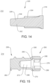
- Extension 242 includes a tapered cross-sectional configuration, as shown in FIG. 14 .
- Extension tapers from a proximal portion towards a distal portion.
- Extension 242 includes a surface 244 that facilitates engaging and retaining of driver 212 with bone screw 214.
- Surface 244 is configured to contact a portion of bone screw 214 at a retention interface 246, as described herein.
- Bone screw 214 includes a distal portion 258 and a proximal portion 260.
- Distal portion 258 includes a shaft 262 configured to penetrate tissue, such as, for example, bone, as described herein.
- Shaft 262 includes a thread form on an outer surface thereof.
- Proximal portion 260 includes socket 266.
- Socket 266 defines recesses 276 configured for disposal of lobes 232, as described herein.
- Each recess 276 includes a drive surface 268 configured for engagement with drive surface 234 at drive interface 238, as described herein, causing drive surface 234 to drive, torque, insert or otherwise rotate bone screw 214 by applying a force to drive surface 268.
- Cavity 280 defines a cavity 280 configured for disposal of extension 242, as described herein.
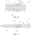
- Cavity 280 includes a tapered configuration, as shown in FIG. 15 .
- Cavity 280 tapers from proximal end 260 to distal end 258.
- Surface 244 of extension 242 is configured to contact surface 272 at retention interface 246, as described herein and shown in FIG. 16 .
- a surface 270 defines a cavity 290.
- Surface 270 includes an undercut, such as, for example, a ramp 292.
- Ramp 292 defines a cone shaped cross section of cavity 190, as shown in FIG. 14 .
- Ramp 292 is oriented to decline from proximal portion 260 towards distal portion 258. Ramp 292 facilitates aligning and/or guiding extension 242 into cavity 280, as described herein.
Landscapes
- Health & Medical Sciences (AREA)
- Orthopedic Medicine & Surgery (AREA)
- Neurology (AREA)
- Surgery (AREA)
- Life Sciences & Earth Sciences (AREA)
- Medical Informatics (AREA)
- Biomedical Technology (AREA)
- Heart & Thoracic Surgery (AREA)
- Engineering & Computer Science (AREA)
- Molecular Biology (AREA)
- Animal Behavior & Ethology (AREA)
- General Health & Medical Sciences (AREA)
- Public Health (AREA)
- Veterinary Medicine (AREA)
- Nuclear Medicine, Radiotherapy & Molecular Imaging (AREA)
- Surgical Instruments (AREA)
- Prostheses (AREA)
Claims (8)
- Wirbelsäulenimplantat (14; 214), umfassend:einen distalen Abschnitt (58; 258), der zum Durchdringen von Gewebe konfiguriert ist; undeinen proximalen Abschnitt (60, 260), der einschließteine Buchse (66), die Aussparungen (76) definiert, die jeweils eine Antriebsoberfläche (68; 268) einschließen,eine Führungsoberfläche (70; 270) undeine Halteoberfläche (72; 272),wobei die Oberflächen von dem proximalen Abschnitt (60; 260) zu dem distalen Abschnitt (58; 258) in einer seriellen Konfiguration aus Antriebsoberfläche (68; 268), Führungsoberfläche (70; 270) und Halteoberfläche (72; 272) angeordnet sind, wobeidie Antriebsoberfläche (68; 268) konfiguriert ist, um mit einer Antriebsoberfläche (34; 234) eines chirurgischen Instruments (12; 212) in Eingriff zu stehen und dadurch eine Antriebsschnittstelle (38; 138; 238) definiert,die Führungsoberfläche (70; 270) einen Hohlraum (90; 290) definiert, der zwischen der Antriebsoberfläche (68; 268) und der Halteoberfläche (72; 272) angeordnet ist, wobei der Hohlraum (90; 290) einen kegelförmigen Querschnitt einschließt, der konfiguriert ist, um das chirurgische Instrument (12; 212) in Eingriff mit der Halteoberfläche (72; 272) auszurichten und zu leiten, unddie Halteoberfläche (72; 272) mit einer Oberfläche (44; 244) einer Verlängerung (42) des chirurgischen Instruments (12; 212) in Eingriff gebracht werden kann, um eine Halteschnittstelle (46; 246) durch ein Definieren eines Hohlraums (80; 280) zu definieren, der sich von dem proximalen Abschnitt (60; 260) in Richtung des distalen Abschnitts (58; 258) verjüngt und für eine Anordnung der Verlängerung (42) des chirurgischen Instruments (12; 212) konfiguriert ist.
- Wirbelsäulenimplantat (14; 214) nach Anspruch 1, wobei die Halteoberfläche (72; 272) und die Oberfläche (44; 244) des chirurgischen Instruments (12; 212) eine Reibungspassung ausbilden.
- Wirbelsäulenimplantat (14; 214) nach Anspruch 1, wobei die Führungsoberfläche (70; 270) einen Spalt (94) definiert, der eine abgewinkelte Oberfläche aufweist, die konfiguriert ist, um die Oberfläche (44; 244) des chirurgischen Instruments (12; 212) mit der Halteoberfläche (72; 272) in Eingriff zu leiten.
- Wirbelsäulenimplantat nach Anspruch 1, wobei die Führungsoberfläche (70; 270) einen Hinterschnitt (92) einschließt.
- Wirbelsäulenimplantat (14; 214) nach Anspruch 1, wobei die Antriebsoberfläche (68; 268) eine hexalobe Geometrie aufweist, die für den Eingriff mit der Antriebsoberfläche (34; 234) des chirurgischen Instruments (12; 212) konfiguriert ist.
- Chirurgisches System (10), umfassend:ein chirurgisches Instrument (12; 212), umfassend einen Treiber, der eine Antriebsoberfläche (34; 234) und eine Halteoberfläche (44; 244) einschließt; unddas Wirbelsäulenimplantat (14; 214) nach Anspruch 1, das Wirbelsäulenimplantat umfassend eine Knochenschraube, die einen Gewindeschaft einschließt;wobei mindestens eine der Halteoberflächen (44, 72; 244, 272) verjüngt ist und die Halteoberflächen (44, 72; 244, 272) in Eingriff gebracht werden können, um das Wirbelsäulenimplantat (14; 214) mit dem chirurgischen Instrument (12; 212) zu halten.
- Chirurgisches System nach Anspruch 6, wobei die Halteoberfläche (44; 244) des chirurgischen Instruments eine verjüngte Konfiguration einschließt.
- Chirurgisches System nach Anspruch 6, wobei die Halteoberfläche (44; 244) des chirurgischen Instruments eine zylindrische Konfiguration einschließt.
Applications Claiming Priority (2)
| Application Number | Priority Date | Filing Date | Title |
|---|---|---|---|
| US16/395,840 US11020154B2 (en) | 2019-04-26 | 2019-04-26 | Surgical instrument and methods of use |
| PCT/US2020/029680 WO2020219786A1 (en) | 2019-04-26 | 2020-04-24 | Surgical instrument and methods of use |
Publications (3)
| Publication Number | Publication Date |
|---|---|
| EP3958770A1 EP3958770A1 (de) | 2022-03-02 |
| EP3958770A4 EP3958770A4 (de) | 2023-01-18 |
| EP3958770B1 true EP3958770B1 (de) | 2024-11-20 |
Family
ID=72922599
Family Applications (1)
| Application Number | Title | Priority Date | Filing Date |
|---|---|---|---|
| EP20794016.4A Active EP3958770B1 (de) | 2019-04-26 | 2020-04-24 | Chirurgisches instrument |
Country Status (5)
| Country | Link |
|---|---|
| US (2) | US11020154B2 (de) |
| EP (1) | EP3958770B1 (de) |
| CN (1) | CN113825462A (de) |
| AU (1) | AU2020262298A1 (de) |
| WO (1) | WO2020219786A1 (de) |
Family Cites Families (38)
| Publication number | Priority date | Publication date | Assignee | Title |
|---|---|---|---|---|
| US2397216A (en) * | 1944-06-16 | 1946-03-26 | Domnic V Stellin | Socket head screw |
| US5139499A (en) | 1989-02-06 | 1992-08-18 | American Cyanamid Company | Screw and driver |
| US5964768A (en) * | 1993-01-21 | 1999-10-12 | Acumed, Inc. | Tapered bone screw with continuously varying pitch |
| FR2712481B1 (fr) * | 1993-11-18 | 1996-01-12 | Graf Henry | Perfectionnements aux stabilisateurs inter-vertébraux souples. |
| DE29520312U1 (de) | 1995-12-21 | 1996-02-08 | Leibinger Medizintech | Knochenschraube |
| US6423067B1 (en) | 1999-04-29 | 2002-07-23 | Theken Surgical Llc | Nonlinear lag screw with captive driving device |
| US6743233B1 (en) | 2000-08-02 | 2004-06-01 | Orthopaedic Biosystems, Ltd., Inc. | Medical screw and method of installation |
| US8828067B2 (en) | 2001-10-18 | 2014-09-09 | Orthoip, Llc | Bone screw system and method |
| US9055981B2 (en) * | 2004-10-25 | 2015-06-16 | Lanx, Inc. | Spinal implants and methods |
| US7819905B2 (en) | 2004-12-17 | 2010-10-26 | Zimmer Spine, Inc. | Self drilling bone screw |
| WO2006069089A2 (en) * | 2004-12-21 | 2006-06-29 | Packaging Service Corporation Of Kentucky | Cervical plate system |
| US7951198B2 (en) * | 2005-05-10 | 2011-05-31 | Acumed Llc | Bone connector with pivotable joint |
| US7967820B2 (en) * | 2006-02-07 | 2011-06-28 | P Tech, Llc. | Methods and devices for trauma welding |
| US8118849B2 (en) | 2006-03-17 | 2012-02-21 | Tornier, Inc. | Bone screw with selectively securable washer |
| GB2437537A (en) * | 2006-04-24 | 2007-10-31 | Jone Edland | Screw head with hexalobular recess and corresponding tool |
| US20090198291A1 (en) | 2006-10-26 | 2009-08-06 | Warsaw Orthopedic, Inc. | Bone screw |
| WO2008122446A1 (en) * | 2007-04-10 | 2008-10-16 | Stryker Trauma Gmbh | Bone screw holding device |
| US9545275B2 (en) | 2007-05-18 | 2017-01-17 | Us Spine, Inc. | Medical device locking mechanisms and related methods and systems |
| US8668725B2 (en) | 2007-07-13 | 2014-03-11 | Southern Spine, Llc | Bone screw |
| US20090326545A1 (en) | 2008-06-26 | 2009-12-31 | Amedica Corporation | Systems and methods for inserting a bone anchor without a pilot hole |
| EP2398413B1 (de) * | 2009-02-10 | 2014-05-21 | Synthes GmbH | Schraube mit kanülierung mit variablem durchmesser und treiber |
| US8529608B2 (en) | 2009-04-28 | 2013-09-10 | Osteomed Llc | Bone plate with a transfixation screw hole |
| US8747472B2 (en) * | 2009-08-14 | 2014-06-10 | Baxano Surgical, Inc. | Spinal therapy device with fixated distraction distance |
| US8500748B2 (en) * | 2009-09-25 | 2013-08-06 | Wasaw Orthopedic, Inc. | Tool and component engaging mechanism |
| US20110082506A1 (en) | 2009-10-02 | 2011-04-07 | Spinefrontier, Inc | Cervical plate assembly |
| EP2496146A1 (de) * | 2009-11-06 | 2012-09-12 | Zvi Laster | Anker und verfahren dafür |
| US8992544B2 (en) | 2010-06-14 | 2015-03-31 | Orthopaedic International, Inc. | Tool and set screw for use in spinal implant systems |
| US8500782B2 (en) * | 2010-07-22 | 2013-08-06 | Aesculap Implant Systems, Llc | Semi-dynamic fixation plate system |
| US8808307B2 (en) * | 2010-10-13 | 2014-08-19 | Pioneer Surgical Technology, Inc. | Driver for a surgical device |
| US10064707B2 (en) * | 2011-07-20 | 2018-09-04 | Parsa T. Zadeh | Self-osteotomizing bone implant and related method |
| ES2563758T3 (es) | 2012-06-18 | 2016-03-16 | Biedermann Technologies Gmbh & Co. Kg | Anclaje de hueso |
| US9724149B2 (en) * | 2013-03-07 | 2017-08-08 | Warsaw Orhtopedic, Inc. | Surgical implant system and method |
| EP2932929B1 (de) | 2014-04-15 | 2017-02-08 | Biedermann Technologies GmbH & Co. KG | Schraubelement zur Verwendung in der spinalen, orthopädischen oder traumatologischen Chirurgie und System mit solch einem Schraubelement und daran angepassten Schraubendreher |
| US9924972B2 (en) | 2015-02-04 | 2018-03-27 | James J. Yue | System and method for spinal fusion |
| GB201600263D0 (en) * | 2016-01-07 | 2016-02-24 | Innovate Orthopaedics Ltd | Fixation device and method of manufacture and use |
| EP3231391B1 (de) * | 2016-04-14 | 2018-12-26 | Neoss Limited | Schraubendreher und schraube für medizinische anwendungen, insbesondere für zahnärztliche anwendungen |
| WO2019102249A1 (en) * | 2017-11-21 | 2019-05-31 | Stryker European Holdings I, Llc | Screw driver, screw and a screw driver system |
| US11540867B2 (en) * | 2019-08-13 | 2023-01-03 | Pioneer Surgical Technology, Inc. | Driver for a bone screw |
-
2019
- 2019-04-26 US US16/395,840 patent/US11020154B2/en active Active
-
2020
- 2020-04-24 AU AU2020262298A patent/AU2020262298A1/en not_active Abandoned
- 2020-04-24 WO PCT/US2020/029680 patent/WO2020219786A1/en not_active Ceased
- 2020-04-24 CN CN202080031074.5A patent/CN113825462A/zh active Pending
- 2020-04-24 EP EP20794016.4A patent/EP3958770B1/de active Active
-
2021
- 2021-05-13 US US17/319,768 patent/US20210259747A1/en not_active Abandoned
Also Published As
| Publication number | Publication date |
|---|---|
| EP3958770A1 (de) | 2022-03-02 |
| WO2020219786A1 (en) | 2020-10-29 |
| US20200337742A1 (en) | 2020-10-29 |
| CN113825462A (zh) | 2021-12-21 |
| AU2020262298A1 (en) | 2021-12-16 |
| US11020154B2 (en) | 2021-06-01 |
| US20210259747A1 (en) | 2021-08-26 |
| EP3958770A4 (de) | 2023-01-18 |
Similar Documents
| Publication | Publication Date | Title |
|---|---|---|
| US11998243B2 (en) | Spinal implant system and method | |
| US20210153904A1 (en) | Spinal implant system and method | |
| US9572605B2 (en) | Surgical instrument and method | |
| US9119685B2 (en) | Surgical instrument and method | |
| US9451999B2 (en) | Surgical instrument adaptor | |
| US9949763B2 (en) | Bone fastener and methods of use | |
| US10492834B2 (en) | Surgical instrument system and method | |
| US11141287B2 (en) | Spinal implant system and method | |
| US20140066945A1 (en) | Surgical implant system and method | |
| US10945806B2 (en) | Surgical guide and methods of use | |
| US10271879B2 (en) | Surgical instrument and methods of use | |
| US20140236247A1 (en) | Surgical implant system and method | |
| US10136902B2 (en) | Surgical instrument and method | |
| WO2024121749A1 (en) | Spinal implant system and method | |
| EP4041110B1 (de) | Wirbelsäulenimplantatsystem | |
| EP3958770B1 (de) | Chirurgisches instrument |
Legal Events
| Date | Code | Title | Description |
|---|---|---|---|
| STAA | Information on the status of an ep patent application or granted ep patent |
Free format text: STATUS: THE INTERNATIONAL PUBLICATION HAS BEEN MADE |
|
| PUAI | Public reference made under article 153(3) epc to a published international application that has entered the european phase |
Free format text: ORIGINAL CODE: 0009012 |
|
| STAA | Information on the status of an ep patent application or granted ep patent |
Free format text: STATUS: REQUEST FOR EXAMINATION WAS MADE |
|
| 17P | Request for examination filed |
Effective date: 20211122 |
|
| AK | Designated contracting states |
Kind code of ref document: A1 Designated state(s): AL AT BE BG CH CY CZ DE DK EE ES FI FR GB GR HR HU IE IS IT LI LT LU LV MC MK MT NL NO PL PT RO RS SE SI SK SM TR |
|
| DAV | Request for validation of the european patent (deleted) | ||
| DAX | Request for extension of the european patent (deleted) | ||
| A4 | Supplementary search report drawn up and despatched |
Effective date: 20221216 |
|
| RIC1 | Information provided on ipc code assigned before grant |
Ipc: A61F 2/46 20060101ALI20221212BHEP Ipc: A61B 17/70 20060101ALI20221212BHEP Ipc: A61B 17/88 20060101ALI20221212BHEP Ipc: A61B 17/86 20060101AFI20221212BHEP |
|
| GRAP | Despatch of communication of intention to grant a patent |
Free format text: ORIGINAL CODE: EPIDOSNIGR1 |
|
| STAA | Information on the status of an ep patent application or granted ep patent |
Free format text: STATUS: GRANT OF PATENT IS INTENDED |
|
| INTG | Intention to grant announced |
Effective date: 20240620 |
|
| GRAS | Grant fee paid |
Free format text: ORIGINAL CODE: EPIDOSNIGR3 |
|
| GRAA | (expected) grant |
Free format text: ORIGINAL CODE: 0009210 |
|
| STAA | Information on the status of an ep patent application or granted ep patent |
Free format text: STATUS: THE PATENT HAS BEEN GRANTED |
|
| AK | Designated contracting states |
Kind code of ref document: B1 Designated state(s): AL AT BE BG CH CY CZ DE DK EE ES FI FR GB GR HR HU IE IS IT LI LT LU LV MC MK MT NL NO PL PT RO RS SE SI SK SM TR |
|
| REG | Reference to a national code |
Ref country code: GB Ref legal event code: FG4D |
|
| REG | Reference to a national code |
Ref country code: CH Ref legal event code: EP |
|
| REG | Reference to a national code |
Ref country code: DE Ref legal event code: R096 Ref document number: 602020041749 Country of ref document: DE |
|
| REG | Reference to a national code |
Ref country code: IE Ref legal event code: FG4D |
|
| REG | Reference to a national code |
Ref country code: LT Ref legal event code: MG9D |
|
| REG | Reference to a national code |
Ref country code: NL Ref legal event code: MP Effective date: 20241120 |
|
| PG25 | Lapsed in a contracting state [announced via postgrant information from national office to epo] |
Ref country code: HR Free format text: LAPSE BECAUSE OF FAILURE TO SUBMIT A TRANSLATION OF THE DESCRIPTION OR TO PAY THE FEE WITHIN THE PRESCRIBED TIME-LIMIT Effective date: 20241120 Ref country code: IS Free format text: LAPSE BECAUSE OF FAILURE TO SUBMIT A TRANSLATION OF THE DESCRIPTION OR TO PAY THE FEE WITHIN THE PRESCRIBED TIME-LIMIT Effective date: 20250320 Ref country code: PT Free format text: LAPSE BECAUSE OF FAILURE TO SUBMIT A TRANSLATION OF THE DESCRIPTION OR TO PAY THE FEE WITHIN THE PRESCRIBED TIME-LIMIT Effective date: 20250320 |
|
| PG25 | Lapsed in a contracting state [announced via postgrant information from national office to epo] |
Ref country code: FI Free format text: LAPSE BECAUSE OF FAILURE TO SUBMIT A TRANSLATION OF THE DESCRIPTION OR TO PAY THE FEE WITHIN THE PRESCRIBED TIME-LIMIT Effective date: 20241120 Ref country code: NL Free format text: LAPSE BECAUSE OF FAILURE TO SUBMIT A TRANSLATION OF THE DESCRIPTION OR TO PAY THE FEE WITHIN THE PRESCRIBED TIME-LIMIT Effective date: 20241120 |
|
| REG | Reference to a national code |
Ref country code: AT Ref legal event code: MK05 Ref document number: 1742863 Country of ref document: AT Kind code of ref document: T Effective date: 20241120 |
|
| PG25 | Lapsed in a contracting state [announced via postgrant information from national office to epo] |
Ref country code: BG Free format text: LAPSE BECAUSE OF FAILURE TO SUBMIT A TRANSLATION OF THE DESCRIPTION OR TO PAY THE FEE WITHIN THE PRESCRIBED TIME-LIMIT Effective date: 20241120 |
|
| PG25 | Lapsed in a contracting state [announced via postgrant information from national office to epo] |
Ref country code: ES Free format text: LAPSE BECAUSE OF FAILURE TO SUBMIT A TRANSLATION OF THE DESCRIPTION OR TO PAY THE FEE WITHIN THE PRESCRIBED TIME-LIMIT Effective date: 20241120 |
|
| PG25 | Lapsed in a contracting state [announced via postgrant information from national office to epo] |
Ref country code: NO Free format text: LAPSE BECAUSE OF FAILURE TO SUBMIT A TRANSLATION OF THE DESCRIPTION OR TO PAY THE FEE WITHIN THE PRESCRIBED TIME-LIMIT Effective date: 20250220 |
|
| PG25 | Lapsed in a contracting state [announced via postgrant information from national office to epo] |
Ref country code: AT Free format text: LAPSE BECAUSE OF FAILURE TO SUBMIT A TRANSLATION OF THE DESCRIPTION OR TO PAY THE FEE WITHIN THE PRESCRIBED TIME-LIMIT Effective date: 20241120 Ref country code: LV Free format text: LAPSE BECAUSE OF FAILURE TO SUBMIT A TRANSLATION OF THE DESCRIPTION OR TO PAY THE FEE WITHIN THE PRESCRIBED TIME-LIMIT Effective date: 20241120 Ref country code: GR Free format text: LAPSE BECAUSE OF FAILURE TO SUBMIT A TRANSLATION OF THE DESCRIPTION OR TO PAY THE FEE WITHIN THE PRESCRIBED TIME-LIMIT Effective date: 20250221 |
|
| PG25 | Lapsed in a contracting state [announced via postgrant information from national office to epo] |
Ref country code: PL Free format text: LAPSE BECAUSE OF FAILURE TO SUBMIT A TRANSLATION OF THE DESCRIPTION OR TO PAY THE FEE WITHIN THE PRESCRIBED TIME-LIMIT Effective date: 20241120 |
|
| PGFP | Annual fee paid to national office [announced via postgrant information from national office to epo] |
Ref country code: FR Payment date: 20250319 Year of fee payment: 6 |
|
| PG25 | Lapsed in a contracting state [announced via postgrant information from national office to epo] |
Ref country code: RS Free format text: LAPSE BECAUSE OF FAILURE TO SUBMIT A TRANSLATION OF THE DESCRIPTION OR TO PAY THE FEE WITHIN THE PRESCRIBED TIME-LIMIT Effective date: 20250220 |
|
| PG25 | Lapsed in a contracting state [announced via postgrant information from national office to epo] |
Ref country code: SM Free format text: LAPSE BECAUSE OF FAILURE TO SUBMIT A TRANSLATION OF THE DESCRIPTION OR TO PAY THE FEE WITHIN THE PRESCRIBED TIME-LIMIT Effective date: 20241120 |
|
| PGFP | Annual fee paid to national office [announced via postgrant information from national office to epo] |
Ref country code: DE Payment date: 20250319 Year of fee payment: 6 |
|
| PG25 | Lapsed in a contracting state [announced via postgrant information from national office to epo] |
Ref country code: DK Free format text: LAPSE BECAUSE OF FAILURE TO SUBMIT A TRANSLATION OF THE DESCRIPTION OR TO PAY THE FEE WITHIN THE PRESCRIBED TIME-LIMIT Effective date: 20241120 |
|
| PG25 | Lapsed in a contracting state [announced via postgrant information from national office to epo] |
Ref country code: EE Free format text: LAPSE BECAUSE OF FAILURE TO SUBMIT A TRANSLATION OF THE DESCRIPTION OR TO PAY THE FEE WITHIN THE PRESCRIBED TIME-LIMIT Effective date: 20241120 |
|
| PG25 | Lapsed in a contracting state [announced via postgrant information from national office to epo] |
Ref country code: RO Free format text: LAPSE BECAUSE OF FAILURE TO SUBMIT A TRANSLATION OF THE DESCRIPTION OR TO PAY THE FEE WITHIN THE PRESCRIBED TIME-LIMIT Effective date: 20241120 |
|
| PG25 | Lapsed in a contracting state [announced via postgrant information from national office to epo] |
Ref country code: SK Free format text: LAPSE BECAUSE OF FAILURE TO SUBMIT A TRANSLATION OF THE DESCRIPTION OR TO PAY THE FEE WITHIN THE PRESCRIBED TIME-LIMIT Effective date: 20241120 |
|
| PG25 | Lapsed in a contracting state [announced via postgrant information from national office to epo] |
Ref country code: CZ Free format text: LAPSE BECAUSE OF FAILURE TO SUBMIT A TRANSLATION OF THE DESCRIPTION OR TO PAY THE FEE WITHIN THE PRESCRIBED TIME-LIMIT Effective date: 20241120 |
|
| PG25 | Lapsed in a contracting state [announced via postgrant information from national office to epo] |
Ref country code: IT Free format text: LAPSE BECAUSE OF FAILURE TO SUBMIT A TRANSLATION OF THE DESCRIPTION OR TO PAY THE FEE WITHIN THE PRESCRIBED TIME-LIMIT Effective date: 20241120 |
|
| REG | Reference to a national code |
Ref country code: DE Ref legal event code: R097 Ref document number: 602020041749 Country of ref document: DE |
|
| PG25 | Lapsed in a contracting state [announced via postgrant information from national office to epo] |
Ref country code: SE Free format text: LAPSE BECAUSE OF FAILURE TO SUBMIT A TRANSLATION OF THE DESCRIPTION OR TO PAY THE FEE WITHIN THE PRESCRIBED TIME-LIMIT Effective date: 20241120 |
|
| PLBE | No opposition filed within time limit |
Free format text: ORIGINAL CODE: 0009261 |
|
| STAA | Information on the status of an ep patent application or granted ep patent |
Free format text: STATUS: NO OPPOSITION FILED WITHIN TIME LIMIT |
|
| 26N | No opposition filed |
Effective date: 20250821 |
|
| REG | Reference to a national code |
Ref country code: CH Ref legal event code: H13 Free format text: ST27 STATUS EVENT CODE: U-0-0-H10-H13 (AS PROVIDED BY THE NATIONAL OFFICE) Effective date: 20251125 |
|
| PG25 | Lapsed in a contracting state [announced via postgrant information from national office to epo] |
Ref country code: LU Free format text: LAPSE BECAUSE OF NON-PAYMENT OF DUE FEES Effective date: 20250424 |
|
| PG25 | Lapsed in a contracting state [announced via postgrant information from national office to epo] |
Ref country code: MC Free format text: LAPSE BECAUSE OF FAILURE TO SUBMIT A TRANSLATION OF THE DESCRIPTION OR TO PAY THE FEE WITHIN THE PRESCRIBED TIME-LIMIT Effective date: 20241120 |
|
| GBPC | Gb: european patent ceased through non-payment of renewal fee |
Effective date: 20250424 |
|
| REG | Reference to a national code |
Ref country code: BE Ref legal event code: MM Effective date: 20250430 |
|
| PG25 | Lapsed in a contracting state [announced via postgrant information from national office to epo] |
Ref country code: GB Free format text: LAPSE BECAUSE OF NON-PAYMENT OF DUE FEES Effective date: 20250424 |
|
| PG25 | Lapsed in a contracting state [announced via postgrant information from national office to epo] |
Ref country code: BE Free format text: LAPSE BECAUSE OF NON-PAYMENT OF DUE FEES Effective date: 20250430 |
|
| PG25 | Lapsed in a contracting state [announced via postgrant information from national office to epo] |
Ref country code: CH Free format text: LAPSE BECAUSE OF NON-PAYMENT OF DUE FEES Effective date: 20250430 |