EP3958386A1 - Battery pack and electric vehicle - Google Patents
Battery pack and electric vehicle Download PDFInfo
- Publication number
- EP3958386A1 EP3958386A1 EP20866937.4A EP20866937A EP3958386A1 EP 3958386 A1 EP3958386 A1 EP 3958386A1 EP 20866937 A EP20866937 A EP 20866937A EP 3958386 A1 EP3958386 A1 EP 3958386A1
- Authority
- EP
- European Patent Office
- Prior art keywords
- battery cell
- battery pack
- separator
- housing
- cell assembly
- Prior art date
- Legal status (The legal status is an assumption and is not a legal conclusion. Google has not performed a legal analysis and makes no representation as to the accuracy of the status listed.)
- Pending
Links
Images



Classifications
-
- H—ELECTRICITY
- H01—ELECTRIC ELEMENTS
- H01M—PROCESSES OR MEANS, e.g. BATTERIES, FOR THE DIRECT CONVERSION OF CHEMICAL ENERGY INTO ELECTRICAL ENERGY
- H01M50/00—Constructional details or processes of manufacture of the non-active parts of electrochemical cells other than fuel cells, e.g. hybrid cells
- H01M50/20—Mountings; Secondary casings or frames; Racks, modules or packs; Suspension devices; Shock absorbers; Transport or carrying devices; Holders
- H01M50/249—Mountings; Secondary casings or frames; Racks, modules or packs; Suspension devices; Shock absorbers; Transport or carrying devices; Holders specially adapted for aircraft or vehicles, e.g. cars or trains
-
- H—ELECTRICITY
- H01—ELECTRIC ELEMENTS
- H01M—PROCESSES OR MEANS, e.g. BATTERIES, FOR THE DIRECT CONVERSION OF CHEMICAL ENERGY INTO ELECTRICAL ENERGY
- H01M50/00—Constructional details or processes of manufacture of the non-active parts of electrochemical cells other than fuel cells, e.g. hybrid cells
- H01M50/30—Arrangements for facilitating escape of gases
-
- H—ELECTRICITY
- H01—ELECTRIC ELEMENTS
- H01M—PROCESSES OR MEANS, e.g. BATTERIES, FOR THE DIRECT CONVERSION OF CHEMICAL ENERGY INTO ELECTRICAL ENERGY
- H01M50/00—Constructional details or processes of manufacture of the non-active parts of electrochemical cells other than fuel cells, e.g. hybrid cells
- H01M50/20—Mountings; Secondary casings or frames; Racks, modules or packs; Suspension devices; Shock absorbers; Transport or carrying devices; Holders
- H01M50/258—Modular batteries; Casings provided with means for assembling
-
- B—PERFORMING OPERATIONS; TRANSPORTING
- B60—VEHICLES IN GENERAL
- B60L—PROPULSION OF ELECTRICALLY-PROPELLED VEHICLES; SUPPLYING ELECTRIC POWER FOR AUXILIARY EQUIPMENT OF ELECTRICALLY-PROPELLED VEHICLES; ELECTRODYNAMIC BRAKE SYSTEMS FOR VEHICLES IN GENERAL; MAGNETIC SUSPENSION OR LEVITATION FOR VEHICLES; MONITORING OPERATING VARIABLES OF ELECTRICALLY-PROPELLED VEHICLES; ELECTRIC SAFETY DEVICES FOR ELECTRICALLY-PROPELLED VEHICLES
- B60L50/00—Electric propulsion with power supplied within the vehicle
- B60L50/50—Electric propulsion with power supplied within the vehicle using propulsion power supplied by batteries or fuel cells
- B60L50/60—Electric propulsion with power supplied within the vehicle using propulsion power supplied by batteries or fuel cells using power supplied by batteries
- B60L50/64—Constructional details of batteries specially adapted for electric vehicles
-
- H—ELECTRICITY
- H01—ELECTRIC ELEMENTS
- H01M—PROCESSES OR MEANS, e.g. BATTERIES, FOR THE DIRECT CONVERSION OF CHEMICAL ENERGY INTO ELECTRICAL ENERGY
- H01M10/00—Secondary cells; Manufacture thereof
- H01M10/42—Methods or arrangements for servicing or maintenance of secondary cells or secondary half-cells
- H01M10/425—Structural combination with electronic components, e.g. electronic circuits integrated to the outside of the casing
-
- H—ELECTRICITY
- H01—ELECTRIC ELEMENTS
- H01M—PROCESSES OR MEANS, e.g. BATTERIES, FOR THE DIRECT CONVERSION OF CHEMICAL ENERGY INTO ELECTRICAL ENERGY
- H01M50/00—Constructional details or processes of manufacture of the non-active parts of electrochemical cells other than fuel cells, e.g. hybrid cells
- H01M50/10—Primary casings; Jackets or wrappings
- H01M50/183—Sealing members
- H01M50/186—Sealing members characterised by the disposition of the sealing members
-
- H—ELECTRICITY
- H01—ELECTRIC ELEMENTS
- H01M—PROCESSES OR MEANS, e.g. BATTERIES, FOR THE DIRECT CONVERSION OF CHEMICAL ENERGY INTO ELECTRICAL ENERGY
- H01M50/00—Constructional details or processes of manufacture of the non-active parts of electrochemical cells other than fuel cells, e.g. hybrid cells
- H01M50/20—Mountings; Secondary casings or frames; Racks, modules or packs; Suspension devices; Shock absorbers; Transport or carrying devices; Holders
- H01M50/204—Racks, modules or packs for multiple batteries or multiple cells
- H01M50/207—Racks, modules or packs for multiple batteries or multiple cells characterised by their shape
- H01M50/209—Racks, modules or packs for multiple batteries or multiple cells characterised by their shape adapted for prismatic or rectangular cells
-
- H—ELECTRICITY
- H01—ELECTRIC ELEMENTS
- H01M—PROCESSES OR MEANS, e.g. BATTERIES, FOR THE DIRECT CONVERSION OF CHEMICAL ENERGY INTO ELECTRICAL ENERGY
- H01M50/00—Constructional details or processes of manufacture of the non-active parts of electrochemical cells other than fuel cells, e.g. hybrid cells
- H01M50/20—Mountings; Secondary casings or frames; Racks, modules or packs; Suspension devices; Shock absorbers; Transport or carrying devices; Holders
- H01M50/204—Racks, modules or packs for multiple batteries or multiple cells
- H01M50/207—Racks, modules or packs for multiple batteries or multiple cells characterised by their shape
- H01M50/211—Racks, modules or packs for multiple batteries or multiple cells characterised by their shape adapted for pouch cells
-
- H—ELECTRICITY
- H01—ELECTRIC ELEMENTS
- H01M—PROCESSES OR MEANS, e.g. BATTERIES, FOR THE DIRECT CONVERSION OF CHEMICAL ENERGY INTO ELECTRICAL ENERGY
- H01M50/00—Constructional details or processes of manufacture of the non-active parts of electrochemical cells other than fuel cells, e.g. hybrid cells
- H01M50/20—Mountings; Secondary casings or frames; Racks, modules or packs; Suspension devices; Shock absorbers; Transport or carrying devices; Holders
- H01M50/233—Mountings; Secondary casings or frames; Racks, modules or packs; Suspension devices; Shock absorbers; Transport or carrying devices; Holders characterised by physical properties of casings or racks, e.g. dimensions
- H01M50/242—Mountings; Secondary casings or frames; Racks, modules or packs; Suspension devices; Shock absorbers; Transport or carrying devices; Holders characterised by physical properties of casings or racks, e.g. dimensions adapted for protecting batteries against vibrations, collision impact or swelling
-
- H—ELECTRICITY
- H01—ELECTRIC ELEMENTS
- H01M—PROCESSES OR MEANS, e.g. BATTERIES, FOR THE DIRECT CONVERSION OF CHEMICAL ENERGY INTO ELECTRICAL ENERGY
- H01M50/00—Constructional details or processes of manufacture of the non-active parts of electrochemical cells other than fuel cells, e.g. hybrid cells
- H01M50/20—Mountings; Secondary casings or frames; Racks, modules or packs; Suspension devices; Shock absorbers; Transport or carrying devices; Holders
- H01M50/289—Mountings; Secondary casings or frames; Racks, modules or packs; Suspension devices; Shock absorbers; Transport or carrying devices; Holders characterised by spacing elements or positioning means within frames, racks or packs
-
- H—ELECTRICITY
- H01—ELECTRIC ELEMENTS
- H01M—PROCESSES OR MEANS, e.g. BATTERIES, FOR THE DIRECT CONVERSION OF CHEMICAL ENERGY INTO ELECTRICAL ENERGY
- H01M50/00—Constructional details or processes of manufacture of the non-active parts of electrochemical cells other than fuel cells, e.g. hybrid cells
- H01M50/20—Mountings; Secondary casings or frames; Racks, modules or packs; Suspension devices; Shock absorbers; Transport or carrying devices; Holders
- H01M50/289—Mountings; Secondary casings or frames; Racks, modules or packs; Suspension devices; Shock absorbers; Transport or carrying devices; Holders characterised by spacing elements or positioning means within frames, racks or packs
- H01M50/293—Mountings; Secondary casings or frames; Racks, modules or packs; Suspension devices; Shock absorbers; Transport or carrying devices; Holders characterised by spacing elements or positioning means within frames, racks or packs characterised by the material
-
- H—ELECTRICITY
- H01—ELECTRIC ELEMENTS
- H01M—PROCESSES OR MEANS, e.g. BATTERIES, FOR THE DIRECT CONVERSION OF CHEMICAL ENERGY INTO ELECTRICAL ENERGY
- H01M50/00—Constructional details or processes of manufacture of the non-active parts of electrochemical cells other than fuel cells, e.g. hybrid cells
- H01M50/30—Arrangements for facilitating escape of gases
- H01M50/342—Non-re-sealable arrangements
- H01M50/3425—Non-re-sealable arrangements in the form of rupturable membranes or weakened parts, e.g. pierced with the aid of a sharp member
-
- H—ELECTRICITY
- H01—ELECTRIC ELEMENTS
- H01M—PROCESSES OR MEANS, e.g. BATTERIES, FOR THE DIRECT CONVERSION OF CHEMICAL ENERGY INTO ELECTRICAL ENERGY
- H01M50/00—Constructional details or processes of manufacture of the non-active parts of electrochemical cells other than fuel cells, e.g. hybrid cells
- H01M50/30—Arrangements for facilitating escape of gases
- H01M50/394—Gas-pervious parts or elements
-
- H—ELECTRICITY
- H01—ELECTRIC ELEMENTS
- H01M—PROCESSES OR MEANS, e.g. BATTERIES, FOR THE DIRECT CONVERSION OF CHEMICAL ENERGY INTO ELECTRICAL ENERGY
- H01M10/00—Secondary cells; Manufacture thereof
- H01M10/42—Methods or arrangements for servicing or maintenance of secondary cells or secondary half-cells
- H01M10/425—Structural combination with electronic components, e.g. electronic circuits integrated to the outside of the casing
- H01M2010/4271—Battery management systems including electronic circuits, e.g. control of current or voltage to keep battery in healthy state, cell balancing
-
- H—ELECTRICITY
- H01—ELECTRIC ELEMENTS
- H01M—PROCESSES OR MEANS, e.g. BATTERIES, FOR THE DIRECT CONVERSION OF CHEMICAL ENERGY INTO ELECTRICAL ENERGY
- H01M2220/00—Batteries for particular applications
- H01M2220/20—Batteries in motive systems, e.g. vehicle, ship, plane
-
- Y—GENERAL TAGGING OF NEW TECHNOLOGICAL DEVELOPMENTS; GENERAL TAGGING OF CROSS-SECTIONAL TECHNOLOGIES SPANNING OVER SEVERAL SECTIONS OF THE IPC; TECHNICAL SUBJECTS COVERED BY FORMER USPC CROSS-REFERENCE ART COLLECTIONS [XRACs] AND DIGESTS
- Y02—TECHNOLOGIES OR APPLICATIONS FOR MITIGATION OR ADAPTATION AGAINST CLIMATE CHANGE
- Y02E—REDUCTION OF GREENHOUSE GAS [GHG] EMISSIONS, RELATED TO ENERGY GENERATION, TRANSMISSION OR DISTRIBUTION
- Y02E60/00—Enabling technologies; Technologies with a potential or indirect contribution to GHG emissions mitigation
- Y02E60/10—Energy storage using batteries
Definitions
- Embodiments of this application relate to the field of battery technologies, and in particular, to a battery pack and an electric vehicle.
- a battery pack is an apparatus that converts external energy into electric energy and stores the electric energy in the battery pack, to supply power to an external device when needed.
- the battery pack includes a battery cell assembly, a battery management assembly, and a housing used for accommodating the two assemblies.
- the battery cell assembly typically includes a plurality of battery cells that are disposed adjacently and connected in series (or in parallel), and the plurality of battery cells can work together to output expected power.
- some manufacturers use glue such as potting glue and silicone to pot the battery pack, so that the glue fills in between an outer surface of the battery cell assembly and an inner wall of the housing, and the entire battery cell assembly is fixed inside the housing, thereby overcoming a defect of displacement of the battery cell assembly in the housing.
- glue such as potting glue and silicone
- thermal runaway may occur in the battery cell assembly to generate high-temperature gas, and the high-temperature gas is difficult to escape in a timely manner because the battery cell assembly is in a sealed state after potting processing. Therefore, thermal runaway of the potted battery pack possibly leads to an accident such as explosion of the battery pack.
- Embodiments of this application are intended to provide a battery pack and an electric vehicle, to resolve the existing technical problem that high-temperature gas cannot be released in a timely manner when thermal runaway occurs in a battery cell assembly of a potted battery pack.
- a battery pack includes a housing, a battery cell assembly, a first separator, a pressure relief portion, and glue.
- the housing is provided with an accommodating cavity.
- the battery cell assembly includes a plurality of stacked battery cells and accommodated in the accommodating cavity.
- the first separator is disposed between the housing and a first side of the battery cell assembly, and is deformed when a temperature is higher than a first threshold.
- the pressure relief portion is disposed in the housing, and the pressure relief portion comes in contact with the first separator or an air channel is provided between the pressure relief portion and the first separator.
- the glue fills a clearance between the housing and at least a partial area outside a first side of the battery cell assembly and is configured to fasten the battery cell assembly to the housing.
- the battery cell includes an electrode assembly, a packaging bag, and a first tab
- the electrode assembly is disposed inside the packaging bag
- the first tab extends from the packaging bag
- the packaging bag is provided with a weakness portion
- the weakness portion is disposed between the first separator and the electrode assembly.
- the packaging bag is provided with a sealing portion, the sealing portion includes a first sealing portion, the first tab extends out of the packaging bag from the first sealing portion, and the weakness portion includes a first weakness portion disposed at the first sealing portion.
- the housing includes a bottom wall and a plurality of side walls, the bottom wall and the plurality of side walls form the accommodating cavity, and the first separator is disposed between the battery cell assembly and the side wall.
- the first separator shrinks when the temperature of the first separator is higher than the first threshold.
- the battery pack includes a circuit board and a mounting bracket that are accommodated in the accommodating cavity, the circuit board is fixed to the mounting bracket, and the air channel includes a first air channel disposed on the mounting bracket.
- the mounting bracket includes a first bracket and a second bracket, both the circuit board and the second bracket are fixed to the first bracket, a clearance is provided between the first bracket and the second bracket, the battery pack includes a flexible circuit board that is connected to the battery cell, the flexible circuit board passes through the clearance and is fixed to the circuit board, and the first air channel is disposed on the first bracket and/or the second bracket.
- the battery cell assembly includes a separator disposed between the battery cells, and the separator is capable of preventing passage of the glue.
- the pressure relief portion is a pressure relief hole provided in or an explosion-proof structure disposed in the housing, and the explosion-proof structure includes an explosion-proof piece.
- the pressure relief hole includes a display light hole and/or a key hole that is provided in the housing and communicates with the accommodating cavity.
- an electric vehicle including the foregoing battery pack.
- the battery pack according to the embodiments of this application includes the housing, the battery cell assembly, the first separator, the pressure relief portion, and the glue.
- the housing is provided with an accommodating cavity.
- the battery cell assembly is disposed in the accommodating cavity and includes a plurality of battery cells.
- the first separator is disposed between the housing and the first side of the battery cell assembly, and is deformed when the temperature is higher than the first threshold.
- the glue fills the clearance between the housing and at least the partial area outside the first side of the battery cell assembly and is configured to fasten the battery cell assembly to the housing.
- the first separator is thermally deformed to form a first pressure relief channel between the housing and the first side of the battery cell assembly. Then, high-temperature gas can escape from the battery pack through the first pressure relief channel and the pressure relief portion. This avoids a drawback that the high-temperature gas cannot escape in a timely manner when thermal runaway occurs in the battery cell assembly, and eliminates a hidden danger of explosion of the battery pack.
- installing includes fixing or limiting an element or apparatus to a specific location or place by means of welding, screwing, clamping, bonding, or the like.
- the element or apparatus may stay still at the specific position or place, or may move within a limited range. After being fixed or limited to the specific position or place, the element or apparatus can be disassembled or cannot be disassembled. This is not limited in the embodiments of this application.
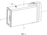
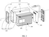
- FIG. 1 and FIG. 2 respectively show a three-dimensional diagram and a schematic exploded view of a battery pack according to this application.
- the battery pack includes a housing 100, a battery cell assembly 200, a first separator 300, a pressure relief portion (not shown), glue (not shown), and a battery management assembly 400.
- the housing 100 is provided with an accommodating cavity 111.
- the battery cell assembly 200 is accommodated in the accommodating cavity 111 and includes a plurality of battery cells 210.
- the first separator 300 is disposed between a first side of the battery cell assembly 200 and the housing 100, and is deformed when a temperature is higher than a first threshold. In this embodiment, the first threshold is lower than a thermal runaway temperature of the battery cell assembly 200.
- the pressure relief portion is disposed in the housing 100, and the pressure relief portion comes in contact with the first separator 300 or an air channel is provided between the pressure relief portion and the first separator 300.
- the glue fills a clearance between the housing 100 and at least a partial area outside the first side of the battery cell assembly 200 and is configured to fasten the battery cell assembly 200 to the housing 100. It should be noted that "a plurality of" described in this application means more than two.
- the housing 100 includes a bottom wall 110, a plurality of side walls 120, and a top wall 130.
- the entire bottom wall 110 presents a plate structure.
- the plurality of side walls 120 form a hollow cuboid enclosure that extends along a first direction X.
- One end of the plurality of side walls 120 is fixed to the bottom wall 110 and forms an enclosure with the bottom wall 110 to from the accommodating cavity 111.
- the plurality of side walls 120 are specifically a first side wall 121, a second side wall 122, a third side wall 123, and a fourth side wall 124. These four side walls are sequentially connected and form the cuboid enclosure.
- the top wall 130 is disposed at one end of the plurality of side walls 120 that faces away from the bottom wall 110, and basically closes an opening of the accommodating cavity 111.
- the battery cell assembly 200 includes a plurality of battery cells 210 that are sequentially stacked along the first direction X.
- the first side of the battery cell assembly 200 faces the first side wall 121 of the housing 100, and the first separator 300 is disposed between the battery cell assembly 200 and the first side wall 121.
- the battery cell 210 includes an electrode assembly 211, a packaging bag 212, and two first tabs 213.
- the electrode assembly 211 is disposed inside the packaging bag 212.
- the packaging bag 212 is formed by bending an entire material to wrap the electrode assembly 211 and sealing peripheral areas of the electrode assembly 211 by means of bonding, hot melting, or the like. The sealed area forms the sealing portion (not shown) of the packaging bag 212.
- a weakness portion (not shown) is provided at the sealing portion of the packaging bag 212. Strength of the weakness portion is less than strength of other portions, so that the high-temperature gas generated by the battery cell 210 can quickly break the weakness portion to escape.
- the weakness portion is disposed between the first separator 300 and the electrode assembly 211. That is, the weakness portion is disposed between the electrode assembly 211 and the first side wall 121.
- first tab 213 is connected to the electrode assembly 211 and the other end extends from the packaging bag 212.
- This pair of first tabs 213 includes a positive tab and a negative tab.
- the sealing portion includes a first sealing portion disposed between the electrode assembly 211 and the first separator 300.
- the first tabs 213 extend out of the packaging bag 212 from the first sealing portion, and the weakness portion includes a first weakness portion disposed at the first sealing portion.
- a side of the battery cell assembly 200 on which the first tabs 213 are disposed is the first side of the battery cell assembly 200 in this embodiment, and both the first weakness portion and the first tabs 213 are disposed on the first side.
- a side of the battery cell assembly 200 that faces away from the first tabs 213 is a second side of the battery cell assembly 200.
- Each of the first tabs 213 includes a connection portion and a bending portion.
- One end of the connection portion is connected to the electrode assembly 211 and the other end passes through the packaging bag 211 and extends away from the packaging bag 212 along a second direction Y.
- One end of the bending portion is connected to an end of the connection portion that faces away from a body and the other end extends along the first direction X.
- bending portions of two mutually opposite first tabs extend towards opposite directions. A pair of bending portions of two adjacent battery cells 210 that are mutually close overlap and are secured by welding.
- the battery cells 210 are connected in series and the first tabs 213 that are opposite between the battery cells 210 are of opposite polarity. It can be understood that in another embodiment of this application, the battery cells 210 may alternatively be connected in parallel. In this case, it is merely necessary to set the mutually connected first tabs to the same polarity on the foregoing basis, connect positive first tabs by using a copper bar, and connect negative first tabs by using another copper bar.
- the battery cell assembly 200 further includes a first support 220.
- the first support 220 is disposed on an end of the packaging bag 212 that is close to the first separator 300 and abuts against the packaging bag 212.
- the first direction X one first support 220 abuts against the packaging bags 212 of two battery cells 210 at the same time.
- the bending portion of the first tab 213 is borne on an end of the first support 220 that faces away from the packaging bag 212.
- the first support 220 is foam and the foam is an air-permeable structure.
- the first support 220 can be used to bear the bending portion of the first tab 213, and can also allow passage of high-temperature gas generated by the battery cells 210.
- the entire first separator 300 presents a flat plate or sheet structure, is accommodated in the accommodating cavity 111 and disposed between the first side and the first side wall 121, and basically covers the first side of the battery cell assembly 200.
- two ends of the first separator 300 respectively abut against the first side of the battery cell assembly 200 and the side wall 120 of the housing along the second direction Y, to ensure that the first separator 300 is compactly mounted between the housing 100 and the battery cell assembly 200 and prevent the first separator 300 from freely moving.
- the first separator 300 may be bonded to the battery cell assembly or the side wall.
- a temperature at which the first separator 300 is deformed is a first threshold.
- the first separator 300 is thermally deformed at a temperature higher than the first threshold, so that a first pressure relief channel is formed between the first side of the battery cell assembly 200 and the housing 100.
- the first threshold is lower than a thermal runaway temperature of the battery cell assembly 200.
- a specific representation form of "deformation" of the first separator 300 may be volume shrinking, melting, or gasification of the first separator 300.
- the first separator 300 shrinks when heated.
- the first separator 300 is made of a fusible material.
- the first separator 300 is made of foam with a relatively low melting point and the foam has elasticity.
- the first separator 300 can implement a gas release and explosion resistance function when thermal runaway occurs in the battery cell assembly, and can also implement a buffer and shock resistance function when the battery pack operates normally, avoiding a strong impact on the battery cell assembly 200.
- the first separator 300 can be deformed under the action of the high-temperature gas and the first pressure relief channel is formed between the first side and the housing.
- the first separator is a bubble bag.
- a limiting groove 310 is disposed at an end of the first separator 300 that faces away from the battery cell assembly 200.
- a limiting protrusion 112 that fits the limiting groove 310 is disposed at a corresponding position on the first side wall.
- the limiting protrusion fits the limiting groove, to facilitate installation, positioning, and securing of the first separator 300.
- the limiting groove 310 extends along the first direction. It can be understood that in another embodiment of this application, the limiting groove may alternatively be disposed on an inner wall of the housing.
- the limiting protrusion is disposed on the first separator.
- the pressure relief portion is disposed in the housing 100 and is thinner than other portions of the housing 100.
- An air channel is provided between the pressure relief portion and the first separator 300.
- the pressure relief portion is configured to allow passage of high-temperature gas when the high-temperature gas is generated due to a factor such as thermal runaway in the battery cell assembly 200, so that the high-temperature gas can escape from the housing 100.
- the pressure relief portion is a pressure relief hole structure.
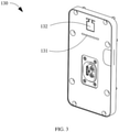
- FIG. 3 shows a three-dimensional diagram of the top wall 130.
- a through-hole structure such as a display light hole 131 and a key hole 132 that communicate with the accommodating cavity 111 is disposed on an outer surface of the top wall 130.
- the pressure relief hole includes the display light hole 131 and/or the key hole 132.
- the high-temperature gas that escapes from the battery cell assembly 200 sequentially passes through the first pressure relief channel, the air channel, and the pressure relief hole, and escapes out of the housing 100.
- the pressure relief portion may alternatively be another structure, provided that the pressure relief portion can allow passage of the high-temperature gas generated by the battery cell assembly.
- the pressure relief portion may alternatively be an explosion-proof structure.
- the explosion-proof structure includes an explosion-proof piece. The high-temperature gas pushes open the explosion-proof piece and flows out of the housing 100.
- the explosion-proof piece may be a low-strength thin area in the housing 100.
- the explosion-proof piece may alternatively be a film structure that is opened in the housing 100 and then covered again.
- the explosion-proof piece may further alternatively be an explosion-proof film structure in an explosion-proof valve installed in the housing 100.
- the pressure relief portion may directly come in contact with the first separator. In this case, gas escaping from the battery cell assembly 200 directly passes through the first pressure relief channel and the pressure relief portion and escapes the housing 100.
- the pressure relief portion may directly come in contact with the first side wall on which the protrusion 112 is disposed in this embodiment.
- the glue fills a clearance between the housing 100 and at least a partial area outside the first side of the battery cell assembly 200, to fasten the battery cell assembly 200 to the housing 100.
- the glue is potting glue. It can be understood that in another embodiment of this application, the glue may alternatively be another curable fluid material such as foamed adhesive and silicone. This is not limited herein.
- the battery pack further includes a buffer assembly 500.
- the buffer assembly 500 has elasticity to some extent, is disposed between at least a partial area outside the first side of the battery cell assembly 200 and an inner wall of the housing 100, and works with the first separator 300 to maintain the battery cells 210 and the first support 220 at relatively fixed positions.
- the buffer assembly 500 can prevent passage of the glue, thereby reducing usage of the glue and decreasing costs.
- the buffer assembly 500 includes an end buffer 510 and a side buffer 520.
- the end buffer 510 is disposed between the second side of the battery cell assembly and the inner wall of the housing 100.
- the side buffer 242 is disposed between the housing 100 and a side between the first side and the second side of the battery cell assembly 200.
- the end buffer 510 and/or the side buffer 520 is foam.
- the battery cell assembly 200 further includes a separator 230 disposed between the battery cells 210.
- the entire separator 230 presents a flat sheet structure and can prevent passage of the glue. Disposition of the separator 230 leaves a safe clearance between two adjacent battery cells 210, and the safe clearance provides some allowance for swelling of the battery cells 210.
- the separator 230 is an elastic piece. When thermal runaway occurs in the battery cell, the separator 230 can effectively absorbing swelling of the battery cell 210 through elastic deformation, thereby avoiding a hidden danger of explosion resulting from a deformation failure and excessive air pressure inside the body of the battery cell 210. Further optionally, the separator 230 is an air-permeable structure.
- the separator 230 is foam.
- the foam can allow passage of the high-temperature gas generated by the battery cell assembly, and also prevent passage of potting glue.
- a hole structure that passes along the first direction X is disposed at a central position of the separator 230. In other words, the entire separator 230 presents a hollow-square shape.
- the hole structure can reduce resistance of the separator 230 on the high-temperature gas during escaping, thereby implementing better gas release and explosion-proof effects.
- the first separator 300 can prevent passage of the glue to prevent permeating of the glue into the weakness portion from the first separator 300.
- the battery management assembly 400 is disposed in the accommodating cavity 111 and includes a circuit board 410, a mounting bracket 420, two copper bars 430 ( FIG. 4 ), and a flexible circuit board 440 ( FIG. 4 ).
- the circuit board 410 is fixed to the mounting bracket 420 and is electrically connected to the battery cell assembly 200.
- the circuit board 410 is configured to control the battery cell assembly 200 to complete the expected work in due time.
- the mounting bracket 420 includes a first bracket 421 and a second bracket 422.
- the first bracket 421 is box-shaped and disposed facing away from the battery cell assembly 200.
- the first bracket 421 limits an accommodating cavity (not shown) that accommodates the circuit board 410 and the second bracket 422.
- the first bracket 421 is disposed on one side of the battery cell assembly 200 and is located on a path along which the high-temperature gas flows from the first separator 300 to the pressure relief portion.
- the circuit board 410 is specifically fixed to the first bracket 421.
- the second bracket 422 is accommodated in the accommodating cavity and fixed to the first bracket 411.
- a clearance 423 is provided between the second bracket 422 and an end of the first bracket 421 that is close to the first side wall.
- the second bracket 422 is configured to mount the two copper bars 430.
- One end of the copper bars 430 located away from the second bracket 422 are connected to a positive electrode or a negative electrode of the battery cell assembly 200.
- One end of the flexible circuit board 440 are electrically connected to the tab of each battery cell 210, and the other end first passes through an end of the first bracket 421 that is close to the battery cell assembly 200 and then passes through the clearance 423, and is fixed and electrically connected to the circuit board 410.
- the air channel includes a first air channel 450 disposed on the mounting bracket 420.
- the first air channel 450 is disposed on both the first bracket 421 and the second bracket 422, and passes through the first bracket 421 and the second bracket 422 in entirety.
- the first air channel 450 includes a square through-hole disposed on the first bracket 421 and a circular through-hole disposed on the second bracket 422.
- the circular through-hole communicates with the square through-hole.
- the high-temperature air escaping from the battery cell assembly 200 sequentially passes through the first pressure relief channel, a partial air channel inside the housing 100, the first air channel, a partial air channel inside the housing 100, and the pressure relief portion, and escapes out of the housing 100.
- the first air channel may alternatively be disposed only on the first bracket.
- the first air channel may alternatively be disposed only on the second bracket.
- the battery pack includes the housing 100, the battery cell assembly 200, the first separator 300, the pressure relief portion, the glue, and the battery management assembly 400.
- the housing 100 is provided with the accommodating cavity 111 used to accommodate the battery cell assembly 200.
- the first separator 300 is disposed between the first side of the battery cell assembly 200 and the inner wall of the housing 100, and is deformed when the temperature is higher than the first preset threshold, so that the first pressure relief channel is formed between the first side of the battery cell assembly 200 and the housing 100.
- the first preset threshold is lower than the thermal runaway temperature of the battery cell assembly 200.
- the pressure relief portion is disposed in the housing 100.
- the glue is provided between the battery cell assembly 200 and the housing 100, and is configured to fill in between the battery cell assembly 200 and the housing 100 and fasten the battery cell assembly 200 to the housing 100.
- the generated high-temperature gas can smoothly escape through the first pressure relief channel and the pressure relief portion. This avoids a drawback that the high-temperature gas cannot escape in a timely manner when thermal runaway occurs in the battery cell assembly, and eliminates the hidden danger of explosion of the battery pack.
- the first side in the foregoing embodiment is an end of the battery cell assembly 200 on which the first tab 213 is disposed, the first side faces the first side wall 121, which is not limited in this application.
- the first side of the battery cell assembly 200 may alternatively face the second side wall 122 rather than the first side wall 121. Accordingly, the first tab 213 still faces the first side wall 121.
- the first separator 300 is disposed between the second side wall 122 and the battery cell assembly 200.
- the first sealing portion and the first weakness portion are still located between the first separator 300 and the electrode assembly 211, except that the first sealing portion and the first weakness portion no longer face the first tab 2123.
- a specific arrangement manner of the first separator 300, the first sealing portion, and the first weakness portion may further have other variations, which are not described herein.
- this application further provides another battery pack.
- the another battery pack is referred to as a second battery pack
- the battery pack in the first embodiment is referred to as a first battery pack.
- the second battery pack differs from the first battery pack mainly in that:
- the first battery pack merely includes one first separator 300, a battery cell 210 includes two first tabs 213, and the two first tabs 213 are both disposed at a pressure relief portion on a first side of a battery cell assembly 200.
- the second battery pack further includes another first separator, and the battery cell 210 includes one first tab and one second tab.
- the another first separator is disposed between a second side of the battery cell assembly and a third side wall.
- a sealing portion further includes a second sealing portion disposed between the battery cell assembly and the third side wall
- a packaging bag further includes a second weakness portion disposed at the second sealing portion.
- the first tab is disposed between the battery cell assembly and a first side wall and is of the same structure as the first tab 213 in the first battery pack.
- the second tab is disposed between the battery cell assembly and the third side wall and is also of the same structure as the first tab 213 in the first battery pack.
- One end of the second tab is connected to the battery cell assembly and the other end extends out of the packaging bag from the second sealing portion.
- a first pressure relief channel and a second pressure relief channel are formed when thermal runaway occurs. High-temperature gas can flow to the pressure relief portion through the first pressure relief channel and the second pressure relief channel, making the gas be exhausted more efficiently. Therefore, the second battery pack has a better explosion-proof effect.
- the pressure relief portion may alternatively be disposed on the third side wall.
- the first weakness portion and/or the second weakness portion may alternatively be disposed not opposite to the tabs. That is, the first weakness portion and/or the second weakness portion are/or disposed between the electrode assembly and a second side wall 122 (or a fourth side wall 124).
- this application further provides an energy storage apparatus, including the battery pack in any one of the foregoing embodiments. Because the energy storage apparatus includes the battery pack, the energy storage apparatus can release high-temperature gas in a timely manner when thermal runaway occurs in the battery pack, eliminating a hidden danger of explosion of the battery pack.
- this application further provides an electric vehicle, including the foregoing energy storage apparatus. That is, the electric vehicle also includes the foregoing battery pack.
- the electric vehicle can release high-temperature gas in a timely manner when thermal runaway occurs in the battery pack, eliminating a hidden danger of explosion of the battery pack.
Landscapes
- Chemical & Material Sciences (AREA)
- Chemical Kinetics & Catalysis (AREA)
- Electrochemistry (AREA)
- General Chemical & Material Sciences (AREA)
- Engineering & Computer Science (AREA)
- Microelectronics & Electronic Packaging (AREA)
- Manufacturing & Machinery (AREA)
- Aviation & Aerospace Engineering (AREA)
- Sustainable Development (AREA)
- Sustainable Energy (AREA)
- Power Engineering (AREA)
- Transportation (AREA)
- Mechanical Engineering (AREA)
- Life Sciences & Earth Sciences (AREA)
- Battery Mounting, Suspending (AREA)
- Gas Exhaust Devices For Batteries (AREA)
Abstract
Description
- Embodiments of this application relate to the field of battery technologies, and in particular, to a battery pack and an electric vehicle.
- A battery pack is an apparatus that converts external energy into electric energy and stores the electric energy in the battery pack, to supply power to an external device when needed. Typically, the battery pack includes a battery cell assembly, a battery management assembly, and a housing used for accommodating the two assemblies. As a core component, the battery cell assembly typically includes a plurality of battery cells that are disposed adjacently and connected in series (or in parallel), and the plurality of battery cells can work together to output expected power.
- To ensure that the battery cell assembly can be stably mounted in the housing without displacement, some manufacturers use glue such as potting glue and silicone to pot the battery pack, so that the glue fills in between an outer surface of the battery cell assembly and an inner wall of the housing, and the entire battery cell assembly is fixed inside the housing, thereby overcoming a defect of displacement of the battery cell assembly in the housing.
- However, the inventor of this application found during implementation of this application that when an exception incident such as a short circuit or overcharging occurs in the internal battery cell assembly of the potted battery pack, thermal runaway may occur in the battery cell assembly to generate high-temperature gas, and the high-temperature gas is difficult to escape in a timely manner because the battery cell assembly is in a sealed state after potting processing. Therefore, thermal runaway of the potted battery pack possibly leads to an accident such as explosion of the battery pack.
- Embodiments of this application are intended to provide a battery pack and an electric vehicle, to resolve the existing technical problem that high-temperature gas cannot be released in a timely manner when thermal runaway occurs in a battery cell assembly of a potted battery pack.
- An embodiment of this application uses the following technical solution to resolve the technical problem:
- A battery pack includes a housing, a battery cell assembly, a first separator, a pressure relief portion, and glue. The housing is provided with an accommodating cavity. The battery cell assembly includes a plurality of stacked battery cells and accommodated in the accommodating cavity. The first separator is disposed between the housing and a first side of the battery cell assembly, and is deformed when a temperature is higher than a first threshold. The pressure relief portion is disposed in the housing, and the pressure relief portion comes in contact with the first separator or an air channel is provided between the pressure relief portion and the first separator. The glue fills a clearance between the housing and at least a partial area outside a first side of the battery cell assembly and is configured to fasten the battery cell assembly to the housing.
- In a further improvement solution of the foregoing technical solution, the battery cell includes an electrode assembly, a packaging bag, and a first tab, the electrode assembly is disposed inside the packaging bag, the first tab extends from the packaging bag, the packaging bag is provided with a weakness portion, and the weakness portion is disposed between the first separator and the electrode assembly.
- In a further improvement solution of the foregoing technical solution, the packaging bag is provided with a sealing portion, the sealing portion includes a first sealing portion, the first tab extends out of the packaging bag from the first sealing portion, and the weakness portion includes a first weakness portion disposed at the first sealing portion.
- In a further improvement solution of the foregoing technical solution, the housing includes a bottom wall and a plurality of side walls, the bottom wall and the plurality of side walls form the accommodating cavity, and the first separator is disposed between the battery cell assembly and the side wall.
- In a further improvement solution of the foregoing technical solution, the first separator shrinks when the temperature of the first separator is higher than the first threshold.
- In a further improvement solution of the foregoing technical solution, the battery pack includes a circuit board and a mounting bracket that are accommodated in the accommodating cavity, the circuit board is fixed to the mounting bracket, and the air channel includes a first air channel disposed on the mounting bracket.
- In a further improvement solution of the foregoing technical solution, the mounting bracket includes a first bracket and a second bracket, both the circuit board and the second bracket are fixed to the first bracket, a clearance is provided between the first bracket and the second bracket, the battery pack includes a flexible circuit board that is connected to the battery cell, the flexible circuit board passes through the clearance and is fixed to the circuit board, and the first air channel is disposed on the first bracket and/or the second bracket.
- In a further improvement solution of the foregoing technical solution, the battery cell assembly includes a separator disposed between the battery cells, and the separator is capable of preventing passage of the glue.
- In a further improvement solution of the foregoing technical solution, the pressure relief portion is a pressure relief hole provided in or an explosion-proof structure disposed in the housing, and the explosion-proof structure includes an explosion-proof piece.
- In a further improvement solution of the foregoing technical solution, the pressure relief hole includes a display light hole and/or a key hole that is provided in the housing and communicates with the accommodating cavity.
- The embodiments of this application further use the following technical solution to resolve the technical problem:
an electric vehicle, including the foregoing battery pack. - Beneficial effects of this application are:
The battery pack according to the embodiments of this application includes the housing, the battery cell assembly, the first separator, the pressure relief portion, and the glue. The housing is provided with an accommodating cavity. The battery cell assembly is disposed in the accommodating cavity and includes a plurality of battery cells. The first separator is disposed between the housing and the first side of the battery cell assembly, and is deformed when the temperature is higher than the first threshold. The glue fills the clearance between the housing and at least the partial area outside the first side of the battery cell assembly and is configured to fasten the battery cell assembly to the housing. Compared with existing battery packets on the market, when thermal runaway occurs in the battery pack according to the embodiments of this application, the first separator is thermally deformed to form a first pressure relief channel between the housing and the first side of the battery cell assembly. Then, high-temperature gas can escape from the battery pack through the first pressure relief channel and the pressure relief portion. This avoids a drawback that the high-temperature gas cannot escape in a timely manner when thermal runaway occurs in the battery cell assembly, and eliminates a hidden danger of explosion of the battery pack. - To describe the technical solutions in the embodiments of this application more clearly, the following briefly describes the accompanying drawings required for describing the embodiments of this application. Apparently, the accompanying drawings in the following description show merely some embodiments of this application, and persons of ordinary skill in the art may still derive other drawings from the structures shown in these accompanying drawings without creative efforts.
-
FIG. 1 is a three-dimensional diagram of a battery pack according to an embodiment of this application; -
FIG. 2 is a schematic exploded view of the battery pack inFIG. 1 ; -
FIG. 3 is a three-dimensional diagram of a top wall inFIG. 2 ; -
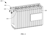
FIG. 4 is a three-dimensional diagram of a battery cell assembly inFIG. 2 ; -
FIG. 5 is an exploded diagram of the battery cell assembly inFIG. 2 ; -
FIG. 6 is a three-dimensional diagram of a battery cell inFIG. 2 ; -
FIG. 7 is a stretch-out view of the battery cell inFIG. 2 ; -
FIG. 8 is a three-dimensional diagram of a first separator inFIG. 2 ; -
FIG. 9 is a three-dimensional diagram of a battery management assembly inFIG. 2 ; and -
FIG. 10 is a projection diagram of the battery management assembly inFIG. 2 in one direction. - For ease of understanding this application, the following describes this application in detail with reference to accompanying drawings and specific embodiments. It should be noted that when an element is expressed as being "fastened/fixed" to another element, it may be directly fastened/fixed to the another element or one or more intermediate elements may be present. When an element is expressed as being "connected" to another element, it may be directly connected to the another element or one or more intermediate elements may be present. The terms "vertical", "horizontal", "left", "right", "inside", "outside", and similar expressions used in this specification are merely for description purposes.
- Unless otherwise defined, all technical and scientific terms used in this specification shall have the same meanings as commonly understood by those skilled in the art to which this application belongs. The terms used in this specification of this application are merely intended to describe specific embodiments but not intended to constitute any limitation on this application. The term "and/or" used in this specification includes any and all combinations of one or more relevant listed items.
- In addition, technical features in different embodiments of this application described below can be combined with each other as long as they do not conflict with each other.
- In this specification, "installing" includes fixing or limiting an element or apparatus to a specific location or place by means of welding, screwing, clamping, bonding, or the like. The element or apparatus may stay still at the specific position or place, or may move within a limited range. After being fixed or limited to the specific position or place, the element or apparatus can be disassembled or cannot be disassembled. This is not limited in the embodiments of this application.
-
FIG. 1 andFIG. 2 respectively show a three-dimensional diagram and a schematic exploded view of a battery pack according to this application. The battery pack includes ahousing 100, abattery cell assembly 200, afirst separator 300, a pressure relief portion (not shown), glue (not shown), and abattery management assembly 400. Thehousing 100 is provided with anaccommodating cavity 111. Thebattery cell assembly 200 is accommodated in theaccommodating cavity 111 and includes a plurality ofbattery cells 210. Thefirst separator 300 is disposed between a first side of thebattery cell assembly 200 and thehousing 100, and is deformed when a temperature is higher than a first threshold. In this embodiment, the first threshold is lower than a thermal runaway temperature of thebattery cell assembly 200. The pressure relief portion is disposed in thehousing 100, and the pressure relief portion comes in contact with thefirst separator 300 or an air channel is provided between the pressure relief portion and thefirst separator 300. The glue fills a clearance between thehousing 100 and at least a partial area outside the first side of thebattery cell assembly 200 and is configured to fasten thebattery cell assembly 200 to thehousing 100. It should be noted that "a plurality of" described in this application means more than two. - For the
housing 100, specifically refer toFIG. 2 . Thehousing 100 includes abottom wall 110, a plurality ofside walls 120, and atop wall 130. The entirebottom wall 110 presents a plate structure. The plurality ofside walls 120 form a hollow cuboid enclosure that extends along a first direction X. One end of the plurality ofside walls 120 is fixed to thebottom wall 110 and forms an enclosure with thebottom wall 110 to from theaccommodating cavity 111. In this embodiment, the plurality ofside walls 120 are specifically afirst side wall 121, asecond side wall 122, athird side wall 123, and afourth side wall 124. These four side walls are sequentially connected and form the cuboid enclosure. Thetop wall 130 is disposed at one end of the plurality ofside walls 120 that faces away from thebottom wall 110, and basically closes an opening of theaccommodating cavity 111. - For the
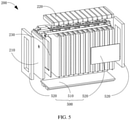
battery cell assembly 200, specifically refer toFIG. 4 andFIG. 5 that respectively show a three-dimensional diagram and a schematic exploded view of thebattery cell assembly 200. Also with reference toFIG. 1 to FIG. 3 , thebattery cell assembly 200 includes a plurality ofbattery cells 210 that are sequentially stacked along the first direction X. The first side of thebattery cell assembly 200 faces thefirst side wall 121 of thehousing 100, and thefirst separator 300 is disposed between thebattery cell assembly 200 and thefirst side wall 121. - For the
battery cell 210, specifically refer toFIG. 6 andFIG. 7 that respectively show a three-dimensional diagram and a stretch-out view of asingle battery cell 210. Also with reference toFIG. 4 andFIG. 5 , thebattery cell 210 includes anelectrode assembly 211, apackaging bag 212, and twofirst tabs 213. Theelectrode assembly 211 is disposed inside thepackaging bag 212. Thepackaging bag 212 is formed by bending an entire material to wrap theelectrode assembly 211 and sealing peripheral areas of theelectrode assembly 211 by means of bonding, hot melting, or the like. The sealed area forms the sealing portion (not shown) of thepackaging bag 212. To facilitate escaping of high-temperature gas inside thebattery cell 210 from a specific position in a timely, targeted, and orderly manner when thermal runaway occurs in thebattery cell 210, a weakness portion (not shown) is provided at the sealing portion of thepackaging bag 212. Strength of the weakness portion is less than strength of other portions, so that the high-temperature gas generated by thebattery cell 210 can quickly break the weakness portion to escape. In this embodiment, the weakness portion is disposed between thefirst separator 300 and theelectrode assembly 211. That is, the weakness portion is disposed between theelectrode assembly 211 and thefirst side wall 121. - One end of the
first tab 213 is connected to theelectrode assembly 211 and the other end extends from thepackaging bag 212. This pair offirst tabs 213 includes a positive tab and a negative tab. Optionally, the sealing portion includes a first sealing portion disposed between theelectrode assembly 211 and thefirst separator 300. Thefirst tabs 213 extend out of thepackaging bag 212 from the first sealing portion, and the weakness portion includes a first weakness portion disposed at the first sealing portion. In this embodiment, a side of thebattery cell assembly 200 on which thefirst tabs 213 are disposed is the first side of thebattery cell assembly 200 in this embodiment, and both the first weakness portion and thefirst tabs 213 are disposed on the first side. For ease of description, a side of thebattery cell assembly 200 that faces away from thefirst tabs 213 is a second side of thebattery cell assembly 200. Each of thefirst tabs 213 includes a connection portion and a bending portion. One end of the connection portion is connected to theelectrode assembly 211 and the other end passes through thepackaging bag 211 and extends away from thepackaging bag 212 along a second direction Y. One end of the bending portion is connected to an end of the connection portion that faces away from a body and the other end extends along the first direction X. Between any twoadjacent battery cells 210, bending portions of two mutually opposite first tabs extend towards opposite directions. A pair of bending portions of twoadjacent battery cells 210 that are mutually close overlap and are secured by welding. - In this embodiment, the
battery cells 210 are connected in series and thefirst tabs 213 that are opposite between thebattery cells 210 are of opposite polarity. It can be understood that in another embodiment of this application, thebattery cells 210 may alternatively be connected in parallel. In this case, it is merely necessary to set the mutually connected first tabs to the same polarity on the foregoing basis, connect positive first tabs by using a copper bar, and connect negative first tabs by using another copper bar. - Further, to prevent deformation of the bending portion due to proneness to damages during dangling, the
battery cell assembly 200 further includes afirst support 220. For details, refer back toFIG. 4 andFIG. 5 . Also with reference to other accompanying drawings, thefirst support 220 is disposed on an end of thepackaging bag 212 that is close to thefirst separator 300 and abuts against thepackaging bag 212. Along the first direction X, onefirst support 220 abuts against thepackaging bags 212 of twobattery cells 210 at the same time. The bending portion of thefirst tab 213 is borne on an end of thefirst support 220 that faces away from thepackaging bag 212. Optionally, thefirst support 220 is foam and the foam is an air-permeable structure. Thefirst support 220 can be used to bear the bending portion of thefirst tab 213, and can also allow passage of high-temperature gas generated by thebattery cells 210. - For the
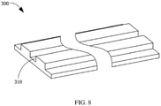
first separator 300, specifically refer toFIG. 8 that shows a three-dimensional diagram of thefirst separator 300. Also with reference to other accompanying drawings, the entirefirst separator 300 presents a flat plate or sheet structure, is accommodated in theaccommodating cavity 111 and disposed between the first side and thefirst side wall 121, and basically covers the first side of thebattery cell assembly 200. In this embodiment, two ends of thefirst separator 300 respectively abut against the first side of thebattery cell assembly 200 and theside wall 120 of the housing along the second direction Y, to ensure that thefirst separator 300 is compactly mounted between thehousing 100 and thebattery cell assembly 200 and prevent thefirst separator 300 from freely moving. In another embodiment, thefirst separator 300 may be bonded to the battery cell assembly or the side wall. A temperature at which thefirst separator 300 is deformed is a first threshold. Thefirst separator 300 is thermally deformed at a temperature higher than the first threshold, so that a first pressure relief channel is formed between the first side of thebattery cell assembly 200 and thehousing 100. The first threshold is lower than a thermal runaway temperature of thebattery cell assembly 200. It should be noted that a specific representation form of "deformation" of thefirst separator 300 may be volume shrinking, melting, or gasification of thefirst separator 300. In this embodiment, thefirst separator 300 shrinks when heated. Optionally, thefirst separator 300 is made of a fusible material. Further optionally, thefirst separator 300 is made of foam with a relatively low melting point and the foam has elasticity. Therefore, thefirst separator 300 can implement a gas release and explosion resistance function when thermal runaway occurs in the battery cell assembly, and can also implement a buffer and shock resistance function when the battery pack operates normally, avoiding a strong impact on thebattery cell assembly 200. Certainly, persons skilled in the art may also make adaptive changes to thefirst separator 300 on the basis of the foregoing embodiment, provided that thefirst separator 300 can be deformed under the action of the high-temperature gas and the first pressure relief channel is formed between the first side and the housing. For example, in other embodiments of this application, the first separator is a bubble bag. - A limiting
groove 310 is disposed at an end of thefirst separator 300 that faces away from thebattery cell assembly 200. Correspondingly, a limitingprotrusion 112 that fits the limitinggroove 310 is disposed at a corresponding position on the first side wall. The limiting protrusion fits the limiting groove, to facilitate installation, positioning, and securing of thefirst separator 300. Optionally, the limitinggroove 310 extends along the first direction. It can be understood that in another embodiment of this application, the limiting groove may alternatively be disposed on an inner wall of the housing. Correspondingly, the limiting protrusion is disposed on the first separator. - The pressure relief portion is disposed in the
housing 100 and is thinner than other portions of thehousing 100. An air channel is provided between the pressure relief portion and thefirst separator 300. The pressure relief portion is configured to allow passage of high-temperature gas when the high-temperature gas is generated due to a factor such as thermal runaway in thebattery cell assembly 200, so that the high-temperature gas can escape from thehousing 100. In this embodiment, the pressure relief portion is a pressure relief hole structure. For details, refer toFIG. 3 that shows a three-dimensional diagram of thetop wall 130. A through-hole structure such as a displaylight hole 131 and akey hole 132 that communicate with theaccommodating cavity 111 is disposed on an outer surface of thetop wall 130. The pressure relief hole includes the displaylight hole 131 and/or thekey hole 132. The high-temperature gas that escapes from thebattery cell assembly 200 sequentially passes through the first pressure relief channel, the air channel, and the pressure relief hole, and escapes out of thehousing 100. It can be understood that in another embodiment of this application, the pressure relief portion may alternatively be another structure, provided that the pressure relief portion can allow passage of the high-temperature gas generated by the battery cell assembly. For example, in another embodiment of this application, the pressure relief portion may alternatively be an explosion-proof structure. The explosion-proof structure includes an explosion-proof piece. The high-temperature gas pushes open the explosion-proof piece and flows out of thehousing 100. The explosion-proof piece may be a low-strength thin area in thehousing 100. The explosion-proof piece may alternatively be a film structure that is opened in thehousing 100 and then covered again. The explosion-proof piece may further alternatively be an explosion-proof film structure in an explosion-proof valve installed in thehousing 100. In addition, the pressure relief portion may directly come in contact with the first separator. In this case, gas escaping from thebattery cell assembly 200 directly passes through the first pressure relief channel and the pressure relief portion and escapes thehousing 100. For example, the pressure relief portion may directly come in contact with the first side wall on which theprotrusion 112 is disposed in this embodiment. - The glue fills a clearance between the
housing 100 and at least a partial area outside the first side of thebattery cell assembly 200, to fasten thebattery cell assembly 200 to thehousing 100. In this embodiment, the glue is potting glue. It can be understood that in another embodiment of this application, the glue may alternatively be another curable fluid material such as foamed adhesive and silicone. This is not limited herein. - In this embodiment, the battery pack further includes a
buffer assembly 500. For details, refer toFIG. 5 and other accompanying drawings. Thebuffer assembly 500 has elasticity to some extent, is disposed between at least a partial area outside the first side of thebattery cell assembly 200 and an inner wall of thehousing 100, and works with thefirst separator 300 to maintain thebattery cells 210 and thefirst support 220 at relatively fixed positions. In this embodiment, thebuffer assembly 500 can prevent passage of the glue, thereby reducing usage of the glue and decreasing costs. Thebuffer assembly 500 includes anend buffer 510 and aside buffer 520. Theend buffer 510 is disposed between the second side of the battery cell assembly and the inner wall of thehousing 100. The side buffer 242 is disposed between thehousing 100 and a side between the first side and the second side of thebattery cell assembly 200. Optionally, theend buffer 510 and/or theside buffer 520 is foam. - Further, the
battery cell assembly 200 further includes aseparator 230 disposed between thebattery cells 210. Specifically, referring toFIG. 5 , theentire separator 230 presents a flat sheet structure and can prevent passage of the glue. Disposition of theseparator 230 leaves a safe clearance between twoadjacent battery cells 210, and the safe clearance provides some allowance for swelling of thebattery cells 210. Optionally, theseparator 230 is an elastic piece. When thermal runaway occurs in the battery cell, theseparator 230 can effectively absorbing swelling of thebattery cell 210 through elastic deformation, thereby avoiding a hidden danger of explosion resulting from a deformation failure and excessive air pressure inside the body of thebattery cell 210. Further optionally, theseparator 230 is an air-permeable structure. After escaping from a center of thebattery cell 210, some high-temperature gas passes through theseparator 230 to thefirst support 220, then sequentially passes through thefirst support 220, the first pressure relief channel, the air channel, and the pressure relief portion, and escapes out of thehousing 100. Further optionally, theseparator 230 is foam. The foam can allow passage of the high-temperature gas generated by the battery cell assembly, and also prevent passage of potting glue. Further optionally, a hole structure that passes along the first direction X is disposed at a central position of theseparator 230. In other words, theentire separator 230 presents a hollow-square shape. The hole structure can reduce resistance of theseparator 230 on the high-temperature gas during escaping, thereby implementing better gas release and explosion-proof effects. Similarly, thefirst separator 300 can prevent passage of the glue to prevent permeating of the glue into the weakness portion from thefirst separator 300. - For the
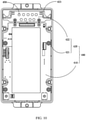
battery management assembly 400, refer toFIG. 9 andFIG. 10 that respectively show a three-dimensional diagram and a projection diagram of thebattery management assembly 400 in one direction. Also with reference to other accompanying drawings, thebattery management assembly 400 is disposed in theaccommodating cavity 111 and includes acircuit board 410, a mountingbracket 420, two copper bars 430 (FIG. 4 ), and a flexible circuit board 440 (FIG. 4 ). Thecircuit board 410 is fixed to the mountingbracket 420 and is electrically connected to thebattery cell assembly 200. Thecircuit board 410 is configured to control thebattery cell assembly 200 to complete the expected work in due time. The mountingbracket 420 includes afirst bracket 421 and asecond bracket 422. Thefirst bracket 421 is box-shaped and disposed facing away from thebattery cell assembly 200. Thefirst bracket 421 limits an accommodating cavity (not shown) that accommodates thecircuit board 410 and thesecond bracket 422. Along the first direction X, thefirst bracket 421 is disposed on one side of thebattery cell assembly 200 and is located on a path along which the high-temperature gas flows from thefirst separator 300 to the pressure relief portion. Thecircuit board 410 is specifically fixed to thefirst bracket 421. Thesecond bracket 422 is accommodated in the accommodating cavity and fixed to the first bracket 411. Aclearance 423 is provided between thesecond bracket 422 and an end of thefirst bracket 421 that is close to the first side wall. Thesecond bracket 422 is configured to mount the two copper bars 430. One end of the copper bars 430 located away from thesecond bracket 422 are connected to a positive electrode or a negative electrode of thebattery cell assembly 200. One end of theflexible circuit board 440 are electrically connected to the tab of eachbattery cell 210, and the other end first passes through an end of thefirst bracket 421 that is close to thebattery cell assembly 200 and then passes through theclearance 423, and is fixed and electrically connected to thecircuit board 410. - To facilitate release of the high-temperature gas, the air channel includes a
first air channel 450 disposed on the mountingbracket 420. In this embodiment, thefirst air channel 450 is disposed on both thefirst bracket 421 and thesecond bracket 422, and passes through thefirst bracket 421 and thesecond bracket 422 in entirety. Specifically, thefirst air channel 450 includes a square through-hole disposed on thefirst bracket 421 and a circular through-hole disposed on thesecond bracket 422. The circular through-hole communicates with the square through-hole. The high-temperature air escaping from thebattery cell assembly 200 sequentially passes through the first pressure relief channel, a partial air channel inside thehousing 100, the first air channel, a partial air channel inside thehousing 100, and the pressure relief portion, and escapes out of thehousing 100. It can be understood that in another embodiment of this application, the first air channel may alternatively be disposed only on the first bracket. When the second bracket is not accommodated in the accommodating cavity of the first bracket, the first air channel may alternatively be disposed only on the second bracket. - The battery pack according to this embodiment of this application includes the
housing 100, thebattery cell assembly 200, thefirst separator 300, the pressure relief portion, the glue, and thebattery management assembly 400. Thehousing 100 is provided with theaccommodating cavity 111 used to accommodate thebattery cell assembly 200. Thefirst separator 300 is disposed between the first side of thebattery cell assembly 200 and the inner wall of thehousing 100, and is deformed when the temperature is higher than the first preset threshold, so that the first pressure relief channel is formed between the first side of thebattery cell assembly 200 and thehousing 100. The first preset threshold is lower than the thermal runaway temperature of thebattery cell assembly 200. The pressure relief portion is disposed in thehousing 100. The glue is provided between thebattery cell assembly 200 and thehousing 100, and is configured to fill in between thebattery cell assembly 200 and thehousing 100 and fasten thebattery cell assembly 200 to thehousing 100. Compared with existing battery packets on the market, when thermal runaway occurs in the battery pack according to this embodiment of this application, the generated high-temperature gas can smoothly escape through the first pressure relief channel and the pressure relief portion. This avoids a drawback that the high-temperature gas cannot escape in a timely manner when thermal runaway occurs in the battery cell assembly, and eliminates the hidden danger of explosion of the battery pack. - It should be understood that even though the first side in the foregoing embodiment is an end of the
battery cell assembly 200 on which thefirst tab 213 is disposed, the first side faces thefirst side wall 121, which is not limited in this application. In another embodiment, the first side of thebattery cell assembly 200 may alternatively face thesecond side wall 122 rather than thefirst side wall 121. Accordingly, thefirst tab 213 still faces thefirst side wall 121. Thefirst separator 300 is disposed between thesecond side wall 122 and thebattery cell assembly 200. In this case, the first sealing portion and the first weakness portion are still located between thefirst separator 300 and theelectrode assembly 211, except that the first sealing portion and the first weakness portion no longer face the first tab 2123. Certainly, a specific arrangement manner of thefirst separator 300, the first sealing portion, and the first weakness portion may further have other variations, which are not described herein. - Based on the same inventive concept, this application further provides another battery pack. For ease of distinguishing it from the battery pack in the first embodiment, the another battery pack is referred to as a second battery pack, and the battery pack in the first embodiment is referred to as a first battery pack. The second battery pack differs from the first battery pack mainly in that:
- The first battery pack merely includes one
first separator 300, abattery cell 210 includes twofirst tabs 213, and the twofirst tabs 213 are both disposed at a pressure relief portion on a first side of abattery cell assembly 200. - However, the second battery pack further includes another first separator, and the
battery cell 210 includes one first tab and one second tab. - Specifically, the another first separator is disposed between a second side of the battery cell assembly and a third side wall. Optionally, a sealing portion further includes a second sealing portion disposed between the battery cell assembly and the third side wall, and a packaging bag further includes a second weakness portion disposed at the second sealing portion. In other words, at least some of high-temperature gas generated by a single battery cell can escape through the second weakness portion and make the first separator disposed between the battery cell assembly and the third side wall shrink, thereby forming a second pressure relief channel between the battery cell assembly and the third side wall, and make the at least some high-temperature gas escape from the housing sequentially through the air channel and the pressure relief portion.
- The first tab is disposed between the battery cell assembly and a first side wall and is of the same structure as the
first tab 213 in the first battery pack. The second tab is disposed between the battery cell assembly and the third side wall and is also of the same structure as thefirst tab 213 in the first battery pack. One end of the second tab is connected to the battery cell assembly and the other end extends out of the packaging bag from the second sealing portion. - Compared with the first battery pack in the first embodiment, in the second battery pack according to this embodiment, a first pressure relief channel and a second pressure relief channel are formed when thermal runaway occurs. High-temperature gas can flow to the pressure relief portion through the first pressure relief channel and the second pressure relief channel, making the gas be exhausted more efficiently. Therefore, the second battery pack has a better explosion-proof effect.
- It can be understood that in another embodiment of the second battery pack, the pressure relief portion may alternatively be disposed on the third side wall. Alternatively, there are a plurality of pressure relief portions. At least one pressure relief portion is disposed on a top wall and at least one pressure relief portion is disposed on the third side wall. In addition, in the second battery pack, the first weakness portion and/or the second weakness portion may alternatively be disposed not opposite to the tabs. That is, the first weakness portion and/or the second weakness portion are/or disposed between the electrode assembly and a second side wall 122 (or a fourth side wall 124).
- Based on the same inventive concept, this application further provides an energy storage apparatus, including the battery pack in any one of the foregoing embodiments. Because the energy storage apparatus includes the battery pack, the energy storage apparatus can release high-temperature gas in a timely manner when thermal runaway occurs in the battery pack, eliminating a hidden danger of explosion of the battery pack.
- Based on the same inventive concept, this application further provides an electric vehicle, including the foregoing energy storage apparatus. That is, the electric vehicle also includes the foregoing battery pack. The electric vehicle can release high-temperature gas in a timely manner when thermal runaway occurs in the battery pack, eliminating a hidden danger of explosion of the battery pack.
- Finally, it should be noted that the foregoing embodiments are merely intended to describe the technical solutions of this application, but not intended to constitute any limitation. Under the idea of this application, the foregoing embodiments or technical features in different embodiments can also be combined, steps can be implemented in any order, and there are many other changes in different aspects of the application as described above, which, for the sake of brevity, are not provided in the detail. Although this application is described in detail with reference to the foregoing embodiments, persons of ordinary skill in the art should understand that modifications can be made to the technical solutions of the foregoing embodiments or equivalent replacements can be made to some technical features therein, and these modifications or replacements do not make an essence of the corresponding technical solutions depart from the scope of the technical solutions of the embodiments of this application.
Claims (11)
- A battery pack, characterized by comprising:a housing, provided with an accommodating cavity;a battery cell assembly, comprising a plurality of stacked battery cells and accommodated in the accommodating cavity;a first separator, disposed between the housing and a first side of the battery cell assembly, and deformed when a temperature is higher than a first threshold;a pressure relief portion, disposed in the housing, wherein the pressure relief portion comes in contact with the first separator or an air channel is provided between the pressure relief portion and the first separator; andglue, filling a clearance between the housing and at least a partial area outside the first side of the battery cell assembly and configured to fasten the battery cell assembly to the housing.
- The battery pack according to claim 1, characterized in that the battery cell comprises an electrode assembly, a packaging bag, and a first tab, the electrode assembly is disposed inside the packaging bag, the first tab extends from the packaging bag, the packaging bag is provided with a weakness portion, and the weakness portion is disposed between the first separator and the electrode assembly.
- The battery pack according to claim 2, characterized in that the packaging bag is provided with a sealing portion, the sealing portion comprises a first sealing portion, the first tab extends out of the packaging bag from the first sealing portion, and the weakness portion comprises a first weakness portion disposed at the first sealing portion.
- The battery pack according to claim 2, characterized in that the housing comprises a bottom wall and a plurality of side walls, the bottom wall and the plurality of side walls form the accommodating cavity, and the first separator is disposed between the battery cell assembly and the side wall.
- The battery pack according to any one of claims 1 to 4, characterized in that the first separator shrinks when the temperature of the first separator is higher than the first threshold.
- The battery pack according to claim 5, characterized in that the battery pack comprises a circuit board and a mounting bracket that are accommodated in the accommodating cavity, the circuit board is fixed to the mounting bracket, and the air channel comprises a first air channel disposed on the mounting bracket.
- The battery pack according to claim 6, characterized in that the mounting bracket comprises a first bracket and a second bracket, both the circuit board and the second bracket are fixed to the first bracket, a clearance is provided between the first bracket and the second bracket, the battery pack comprises a flexible circuit board that is connected to the battery cell, the flexible circuit board passes through the clearance and is fixed to the circuit board, and the first air channel is disposed on the first bracket and/or the second bracket.
- The battery pack according to claim 5, characterized in that the battery cell assembly comprises a separator disposed between the battery cells, and the separator is capable of preventing passage of the glue.
- The battery pack according to claim 1, characterized in that the pressure relief portion is a pressure relief hole provided in or an explosion-proof structure disposed in the housing, and the explosion-proof structure comprises an explosion-proof piece.
- The battery pack according to claim 9, characterized in that the pressure relief hole comprises a display light hole and/or a key hole that is provided in the housing and communicates with the accommodating cavity.
- An electric vehicle, characterized by comprising the battery pack according to any one of claims 1 to 10.
Applications Claiming Priority (1)
| Application Number | Priority Date | Filing Date | Title |
|---|---|---|---|
| PCT/CN2020/096840 WO2021253330A1 (en) | 2020-06-18 | 2020-06-18 | Battery pack and electric vehicle |
Publications (2)
| Publication Number | Publication Date |
|---|---|
| EP3958386A1 true EP3958386A1 (en) | 2022-02-23 |
| EP3958386A4 EP3958386A4 (en) | 2023-05-03 |
Family
ID=78415662
Family Applications (1)
| Application Number | Title | Priority Date | Filing Date |
|---|---|---|---|
| EP20866937.4A Pending EP3958386A4 (en) | 2020-06-18 | 2020-06-18 | BATTERY PACK AND ELECTRIC VEHICLE |
Country Status (4)
| Country | Link |
|---|---|
| US (2) | US12009542B2 (en) |
| EP (1) | EP3958386A4 (en) |
| CN (1) | CN113646960B (en) |
| WO (1) | WO2021253330A1 (en) |
Families Citing this family (14)
| Publication number | Priority date | Publication date | Assignee | Title |
|---|---|---|---|---|
| CN114914641B (en) * | 2021-02-07 | 2023-06-23 | 宁德时代新能源科技股份有限公司 | Battery, power utilization device, method for manufacturing battery, and apparatus therefor |
| US20240421413A1 (en) * | 2021-12-20 | 2024-12-19 | Lg Energy Solution, Ltd. | Battery module and battery pack and vehicle comprising the same |
| CN114937843A (en) * | 2022-03-31 | 2022-08-23 | 东莞新能安科技有限公司 | Group battery, foaming adhesive and consumer |
| DE102022108462A1 (en) * | 2022-04-07 | 2023-10-12 | Man Truck & Bus Se | Energy storage device with at least one seal |
| CN115954562A (en) * | 2022-12-30 | 2023-04-11 | 厦门新能达科技有限公司 | Battery Packs and Consumers |
| CN116053697B (en) * | 2022-12-31 | 2025-04-08 | 宁德新能源科技有限公司 | Battery core and electricity utilization device |
| CN219717163U (en) * | 2023-02-23 | 2023-09-19 | 蜂巢能源科技股份有限公司 | Battery cell |
| CN220569847U (en) * | 2023-05-26 | 2024-03-08 | 阳光电源股份有限公司 | An energy storage module and its sealing structure |
| WO2025045051A1 (en) * | 2023-08-30 | 2025-03-06 | 双澳储能科技(西安)有限公司 | High-capacity battery and cartridge |
| WO2025097278A1 (en) * | 2023-11-06 | 2025-05-15 | 宁德时代新能源科技股份有限公司 | Battery cell, battery, and electric device |
| CN222072062U (en) * | 2024-04-01 | 2024-11-26 | 株式会社Aesc日本 | Battery Pack |
| CN118589008B (en) * | 2024-05-23 | 2025-01-14 | 苏州市纬迪精密控胶系统有限公司 | A glue filling tool for a lithium-ion battery single-chip cell |
| CN118572298B (en) * | 2024-08-01 | 2024-12-03 | 江苏正力新能电池技术股份有限公司 | Battery pack and power device |
| CN121642404A (en) * | 2024-08-28 | 2026-03-10 | 小米汽车科技有限公司 | Battery pack and its assembly method, vehicle |
Family Cites Families (11)
| Publication number | Priority date | Publication date | Assignee | Title |
|---|---|---|---|---|
| WO2008130148A1 (en) | 2007-04-20 | 2008-10-30 | Lg Chem, Ltd. | Battery cell of improved safety |
| WO2013011748A1 (en) * | 2011-07-15 | 2013-01-24 | Necエナジーデバイス株式会社 | Battery module |
| JP6261449B2 (en) * | 2014-05-30 | 2018-01-17 | ダイキョーニシカワ株式会社 | Battery module |
| EP3410512B1 (en) | 2016-01-26 | 2022-02-16 | Sanyo Electric Co., Ltd. | Battery pack |
| CN206490119U (en) * | 2017-02-28 | 2017-09-12 | 宁德时代新能源科技股份有限公司 | Battery modules |
| CN108232064A (en) * | 2017-12-22 | 2018-06-29 | 天津力神特种电源科技股份公司 | A kind of temperature control safeguard structure of lithium battery system |
| CN207818695U (en) * | 2018-01-25 | 2018-09-04 | 宁德时代新能源科技股份有限公司 | Battery Unit and Battery Module |
| CN108565363B (en) * | 2018-06-22 | 2026-02-24 | 深圳市比克动力电池有限公司 | Secondary battery top cover and secondary battery |
| CN209401662U (en) * | 2019-03-28 | 2019-09-17 | 宁德时代新能源科技股份有限公司 | battery pack |
| CN110148692A (en) * | 2019-05-10 | 2019-08-20 | 北京新能源汽车股份有限公司 | Battery module and have its vehicle |
| CN209981287U (en) * | 2019-08-15 | 2020-01-21 | 宁德时代新能源科技股份有限公司 | Lid assembly for secondary battery and secondary battery |
-
2020
- 2020-06-18 WO PCT/CN2020/096840 patent/WO2021253330A1/en not_active Ceased
- 2020-06-18 US US17/281,358 patent/US12009542B2/en active Active
- 2020-06-18 CN CN202080025136.1A patent/CN113646960B/en active Active
- 2020-06-18 EP EP20866937.4A patent/EP3958386A4/en active Pending
-
2024
- 2024-05-01 US US18/651,823 patent/US20240283080A1/en active Pending
Also Published As
| Publication number | Publication date |
|---|---|
| US12009542B2 (en) | 2024-06-11 |
| EP3958386A4 (en) | 2023-05-03 |
| CN113646960A (en) | 2021-11-12 |
| US20220200092A1 (en) | 2022-06-23 |
| CN113646960B (en) | 2023-06-27 |
| US20240283080A1 (en) | 2024-08-22 |
| WO2021253330A1 (en) | 2021-12-23 |
Similar Documents
| Publication | Publication Date | Title |
|---|---|---|
| US20240283080A1 (en) | Battery pack and electric vehicle | |
| EP3716392B1 (en) | Battery module having improved cooling structure | |
| CN212323146U (en) | Battery packs and electric vehicles | |
| JP6847864B2 (en) | Battery pack | |
| KR102665192B1 (en) | Battery pack and device including the same | |
| KR102922130B1 (en) | Battery pack and device including the same | |
| CN116759726A (en) | Battery module and battery pack including the battery module | |
| WO2021253329A1 (en) | Battery pack and electric vehicle | |
| JP5398673B2 (en) | battery | |
| WO2014027783A1 (en) | Battery module comprising venting guidance portion | |
| KR101261729B1 (en) | Battery Pack | |
| CN212434750U (en) | Battery case and battery pack with same | |
| CN212751049U (en) | Battery packs and electric vehicles | |
| KR20230020894A (en) | Battery pack and vehicle including the same | |
| CN212323145U (en) | Battery packs and electric vehicles | |
| KR20240012290A (en) | Battery module and, battery pack and vehicle including same | |
| CN112259795A (en) | Battery cell assembling method and battery cell | |
| KR20230021607A (en) | Battery pack and vehicle including the same | |
| KR20250007973A (en) | Battery Module | |
| KR20180101103A (en) | Catridge and battery module including the same | |
| KR101080130B1 (en) | Battery Pack Guaranteeing Safety at Electrolyte Leakage | |
| KR102772824B1 (en) | Battery pack with improved safety | |
| KR102054413B1 (en) | Battery Pack | |
| JP7789914B2 (en) | Battery module, battery pack including the same, and automobile including the same | |
| EP4376155A1 (en) | Battery pack with improved safety |
Legal Events
| Date | Code | Title | Description |
|---|---|---|---|
| STAA | Information on the status of an ep patent application or granted ep patent |
Free format text: STATUS: UNKNOWN |
|
| STAA | Information on the status of an ep patent application or granted ep patent |
Free format text: STATUS: THE INTERNATIONAL PUBLICATION HAS BEEN MADE |
|
| PUAI | Public reference made under article 153(3) epc to a published international application that has entered the european phase |
Free format text: ORIGINAL CODE: 0009012 |
|
| STAA | Information on the status of an ep patent application or granted ep patent |
Free format text: STATUS: REQUEST FOR EXAMINATION WAS MADE |
|
| 17P | Request for examination filed |
Effective date: 20210330 |
|
| AK | Designated contracting states |
Kind code of ref document: A1 Designated state(s): AL AT BE BG CH CY CZ DE DK EE ES FI FR GB GR HR HU IE IS IT LI LT LU LV MC MK MT NL NO PL PT RO RS SE SI SK SM TR |
|
| A4 | Supplementary search report drawn up and despatched |
Effective date: 20230403 |
|
| RIC1 | Information provided on ipc code assigned before grant |
Ipc: H01M 50/342 20210101ALI20230328BHEP Ipc: H01M 50/258 20210101AFI20230328BHEP |
|
| DAV | Request for validation of the european patent (deleted) | ||
| DAX | Request for extension of the european patent (deleted) | ||
| RAP1 | Party data changed (applicant data changed or rights of an application transferred) |
Owner name: NINGDE AMPEREX TECHNOLOGY LIMITED |
|
| RAP3 | Party data changed (applicant data changed or rights of an application transferred) |
Owner name: NINGDE AMPEREX TECHNOLOGY LIMITED |