EP3958084A1 - Method of controlling motion of a mobile warning triangle and mobile warning triangle - Google Patents
Method of controlling motion of a mobile warning triangle and mobile warning triangle Download PDFInfo
- Publication number
- EP3958084A1 EP3958084A1 EP21176908.8A EP21176908A EP3958084A1 EP 3958084 A1 EP3958084 A1 EP 3958084A1 EP 21176908 A EP21176908 A EP 21176908A EP 3958084 A1 EP3958084 A1 EP 3958084A1
- Authority
- EP
- European Patent Office
- Prior art keywords
- warning triangle
- mobile warning
- sensor
- color
- central axis
- Prior art date
- Legal status (The legal status is an assumption and is not a legal conclusion. Google has not performed a legal analysis and makes no representation as to the accuracy of the status listed.)
- Granted
Links
- 238000000034 method Methods 0.000 title claims abstract description 30
- 238000013500 data storage Methods 0.000 claims description 8
- 239000003086 colorant Substances 0.000 abstract description 5
- 238000010586 diagram Methods 0.000 description 3
- 230000006870 function Effects 0.000 description 3
- 230000001154 acute effect Effects 0.000 description 2
Images


Classifications
-
- G—PHYSICS
- G05—CONTROLLING; REGULATING
- G05D—SYSTEMS FOR CONTROLLING OR REGULATING NON-ELECTRIC VARIABLES
- G05D1/00—Control of position, course or altitude of land, water, air, or space vehicles, e.g. automatic pilot
- G05D1/02—Control of position or course in two dimensions
- G05D1/021—Control of position or course in two dimensions specially adapted to land vehicles
- G05D1/0231—Control of position or course in two dimensions specially adapted to land vehicles using optical position detecting means
- G05D1/0244—Control of position or course in two dimensions specially adapted to land vehicles using optical position detecting means using reflecting strips
-
- G—PHYSICS
- G05—CONTROLLING; REGULATING
- G05D—SYSTEMS FOR CONTROLLING OR REGULATING NON-ELECTRIC VARIABLES
- G05D1/00—Control of position, course or altitude of land, water, air, or space vehicles, e.g. automatic pilot
- G05D1/02—Control of position or course in two dimensions
- G05D1/021—Control of position or course in two dimensions specially adapted to land vehicles
- G05D1/0212—Control of position or course in two dimensions specially adapted to land vehicles with means for defining a desired trajectory
- G05D1/0214—Control of position or course in two dimensions specially adapted to land vehicles with means for defining a desired trajectory in accordance with safety or protection criteria, e.g. avoiding hazardous areas
-
- B—PERFORMING OPERATIONS; TRANSPORTING
- B60—VEHICLES IN GENERAL
- B60Q—ARRANGEMENT OF SIGNALLING OR LIGHTING DEVICES, THE MOUNTING OR SUPPORTING THEREOF OR CIRCUITS THEREFOR, FOR VEHICLES IN GENERAL
- B60Q7/00—Arrangement or adaptation of portable emergency signal devices on vehicles
-
- E—FIXED CONSTRUCTIONS
- E01—CONSTRUCTION OF ROADS, RAILWAYS, OR BRIDGES
- E01F—ADDITIONAL WORK, SUCH AS EQUIPPING ROADS OR THE CONSTRUCTION OF PLATFORMS, HELICOPTER LANDING STAGES, SIGNS, SNOW FENCES, OR THE LIKE
- E01F9/00—Arrangement of road signs or traffic signals; Arrangements for enforcing caution
- E01F9/60—Upright bodies, e.g. marker posts or bollards; Supports for road signs
- E01F9/623—Upright bodies, e.g. marker posts or bollards; Supports for road signs characterised by form or by structural features, e.g. for enabling displacement or deflection
- E01F9/627—Upright bodies, e.g. marker posts or bollards; Supports for road signs characterised by form or by structural features, e.g. for enabling displacement or deflection self-righting after deflection or displacement
- E01F9/629—Traffic guidance, warning or control posts, bollards, pillars or like upstanding bodies or structures
-
- G—PHYSICS
- G05—CONTROLLING; REGULATING
- G05D—SYSTEMS FOR CONTROLLING OR REGULATING NON-ELECTRIC VARIABLES
- G05D1/00—Control of position, course or altitude of land, water, air, or space vehicles, e.g. automatic pilot
- G05D1/02—Control of position or course in two dimensions
- G05D1/021—Control of position or course in two dimensions specially adapted to land vehicles
- G05D1/0231—Control of position or course in two dimensions specially adapted to land vehicles using optical position detecting means
-
- G—PHYSICS
- G05—CONTROLLING; REGULATING
- G05D—SYSTEMS FOR CONTROLLING OR REGULATING NON-ELECTRIC VARIABLES
- G05D1/00—Control of position, course or altitude of land, water, air, or space vehicles, e.g. automatic pilot
- G05D1/02—Control of position or course in two dimensions
- G05D1/021—Control of position or course in two dimensions specially adapted to land vehicles
- G05D1/0276—Control of position or course in two dimensions specially adapted to land vehicles using signals provided by a source external to the vehicle
-
- G—PHYSICS
- G06—COMPUTING; CALCULATING OR COUNTING
- G06V—IMAGE OR VIDEO RECOGNITION OR UNDERSTANDING
- G06V10/00—Arrangements for image or video recognition or understanding
- G06V10/40—Extraction of image or video features
- G06V10/56—Extraction of image or video features relating to colour
-
- G—PHYSICS
- G06—COMPUTING; CALCULATING OR COUNTING
- G06V—IMAGE OR VIDEO RECOGNITION OR UNDERSTANDING
- G06V20/00—Scenes; Scene-specific elements
- G06V20/50—Context or environment of the image
- G06V20/56—Context or environment of the image exterior to a vehicle by using sensors mounted on the vehicle
- G06V20/588—Recognition of the road, e.g. of lane markings; Recognition of the vehicle driving pattern in relation to the road
-
- G—PHYSICS
- G09—EDUCATION; CRYPTOGRAPHY; DISPLAY; ADVERTISING; SEALS
- G09F—DISPLAYING; ADVERTISING; SIGNS; LABELS OR NAME-PLATES; SEALS
- G09F13/00—Illuminated signs; Luminous advertising
- G09F13/16—Signs formed of or incorporating reflecting elements or surfaces, e.g. warning signs having triangular or other geometrical shape
-
- G—PHYSICS
- G09—EDUCATION; CRYPTOGRAPHY; DISPLAY; ADVERTISING; SEALS
- G09F—DISPLAYING; ADVERTISING; SIGNS; LABELS OR NAME-PLATES; SEALS
- G09F7/00—Signs, name or number plates, letters, numerals, or symbols; Panels or boards
-
- G—PHYSICS
- G09—EDUCATION; CRYPTOGRAPHY; DISPLAY; ADVERTISING; SEALS
- G09F—DISPLAYING; ADVERTISING; SIGNS; LABELS OR NAME-PLATES; SEALS
- G09F7/00—Signs, name or number plates, letters, numerals, or symbols; Panels or boards
- G09F2007/005—Signs associated with a sensor
Abstract
If no deviation is recognized in the colors, the mobile warning triangle continues moving forward.
If a deviation in colors is recognized, the mobile warning triangle is controlled to hunt to the left and right through one or more predetermined angles to try to detect or redetect the lane marking.
Description
- The subject matter herein generally relates to road safety.
- A warning triangle raised at a distance from a stationary vehicle or other obstruction warns other vehicles of an obstruction or other dangers ahead. A mobile warning triangle sent out towards a point of placement and in motion may deviate from a correct path.
- Implementations of the present technology will now be described, by way of example only, with reference to the attached figures.
-
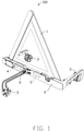
FIG. 1 is a schematic diagram of an embodiment of a mobile warning triangle. -
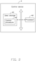
FIG. 2 is a block diagram of an embodiment of a control device of the mobile warning triangle ofFIG. 1 . -
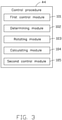
FIG. 3 is a block diagram of an embodiment of a control procedure of the control device ofFIG. 2 . -
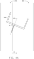
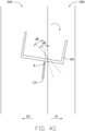
FIGS. 4A ,4B ,4C ,4D ,4E ,4F , and4G show the mobile warning triangle ofFIG. 1 in motion along a lane marking with a sensor in a working state. -
FIG. 5 is a flowchart of a method in an embodiment for controlling the motion of the mobile warning triangle ofFIG. 1 . - It will be appreciated that for simplicity and clarity of illustration, where appropriate, reference numerals have been repeated among the different figures to indicate corresponding or analogous elements. In addition, numerous specific details are set forth in order to provide a thorough understanding of the embodiments described herein. However, it will be understood by those of ordinary skill in the art that the embodiments described herein can be practiced without these specific details. In other instances, methods, procedures, and components have not been described in detail so as not to obscure the related relevant feature being described. Also, the description is not to be considered as limiting the scope of the embodiments described herein. The drawings are not necessarily to scale and the proportions of certain parts may be exaggerated to better illustrate details and features of the present disclosure. It should be noted that references to "an" or "one" embodiment in this disclosure are not necessarily to the same embodiment, and such references mean "at least one".
- Several definitions that apply throughout this disclosure will now be presented.
- The term "coupled" is defined as connected, whether directly or indirectly through intervening components, and is not necessarily limited to physical connections. The connection can be such that the objects are permanently connected or releasably connected. The term "comprising," when utilized, means "including, but not necessarily limited to"; it specifically indicates open-ended inclusion or membership in the so-described combination, group, series, and the like.
-
FIG. 1 illustrates amobile warning triangle 100 in accordance with an exemplary embodiment. - The
mobile warning triangle 100 comprises awarning triangle 1, abase 2, threewheels 3, acontrol device 4, amotor 5, and asensor 6. Thecontrol device 4 can control themobile warning triangle 100 to move. Thecontrol device 4 can further cause and correct a moving direction of themobile warning triangle 100. - The
mobile warning triangle 100 can be raised and placed at a first predetermined distance from a stationary object. The first predetermined distance can be 100 meters or 150 meters for example. - In one embodiment, the
sensor 6 can be a color-sensitive sensor. For example, thesensor 6 is TCS3200 color sensor. In the TCS3200 color sensor, if a color filter is selected, only a desired color is allowed to pass, and other primary colors are blocked. If a red filter is selected, the incident red light can be passed, but blue light and green light are blocked, and intensity of the red light can be obtained. Similarly, by selecting other filters, blue light can be passed, obtained, and measured for intensity, and similarly for green light. Then, the colors and intensities of the light incident on the TCS3200 color sensor can be recognized. - In one embodiment, the
sensor 6 can be installed at the bottom of themobile warning triangle 100, such as the bottom of thewarning triangle 1 or the bottom of thebase 2, to better detect a lane marking. For example, when themobile warning triangle 100 is moving, thesensor 6 can be directed downward to detect any lane marking. - In one embodiment, the
sensor 6 can acquire color information of any scene or object or marking towards which the sensor may be directed. - In one embodiment, two or more sensors can be installed at the bottom of the
mobile warning triangle 100, the number of sensors can be according to an actual application. - Referring to
FIG. 2 , thecontrol device 4 can comprise at least onedata storage 40, at least oneprocessor 42, and acontrol procedure 44. - In one embodiment, the
data storage 40 can be in themobile warning triangle 100, or can be a separate external memory card, such as an SM card (Smart Media Card), an SD card (Secure Digital Card), or the like. Thedata storage 40 can include various types of non-transitory computer-readable storage mediums. For example, thedata storage 40 can be an internal storage system, such as a flash memory, a random access memory (RAM) for the temporary storage of information, and/or a read-only memory (ROM) for permanent storage of information. Thedata storage 40 can also be an external storage system, such as a hard disk, a storage card, or a data storage medium. Theprocessor 42 can be a central processing unit (CPU), a microprocessor, or other data processor chip that achieves functions of themobile warning triangle 100. -
FIG. 3 illustrates thecontrol procedure 44 as comprising a plurality of modules, such as afirst control module 101, a determiningmodule 102, arotating module 103, a calculatingmodule 104, and asecond control module 105. The modules 101-105 can comprise one or more software programs in the form of computerized codes stored in thedata storage 40. The computerized codes can include instructions that can be executed by theprocessor 42 to provide functions for the modules 101-105. - The
mobile warning triangle 100 is placed on a road, and thesensor 6 can detect a lane marking of the road as an example. - The
first control module 101 can control themobile warning triangle 100 to move forward or backward and acquire color information detected by thesensor 6 when themobile warning triangle 100 is placed on the road and thesensor 6 detects the lane markings of the road. - The
first control module 101 can control themobile warning triangle 100 to move forward or backward when themobile warning triangle 100 is placed on the lane 300 (as shown inFIG. 4A ) of a road or other traversable surface. Thesensor 6 can detect the lane marking 200 (as shown inFIG. 4A ). Thesensor 6 can acquire the color information when themobile warning triangle 100 is moving forward or backward. - In one embodiment, the
lane markings 200 of the road are white and yellow. Along an expressway or a provincial highway, thelane markings 200 are white markings and yellow markings, the road itself is black. There is a significant difference in color between the road and thelane markings 200. Thesensor 6 can easily detect and identify thelane markings 200. When there is an obstacle on the road, themobile warning triangle 100 is raised at the first predetermined distance from the obstacle to warn other vehicles. A user can place themobile warning triangle 100 on thelane 300 in which the obstacle, a vehicle for example, is stationary, and aim thesensor 6 at the lane marking 200 of the lane 300 (for example a white marking). Thesensors 6 can detect the lane marking 200 to control themobile warning triangle 100 to move forward along the lane marking 200. When themobile warning triangle 100 is placed on thelane 300 and thesensor 6 detects the lane marking 200 of thelane 300, thefirst control module 101 controls themobile warning triangle 100 to move forward. When themobile warning triangle 100 is moving, thefirst control module 101 can obtain the color information detected by thesensors 6 in real time to determine correct tracking or a lane departure by themobile warning triangle 100. - The determining
module 102 determines whether the color information detected by thesensor 6 is the color of the lane marking 200. - In one embodiment, when the
first control module 101 obtains information as to color detected by thesensor 6, the determiningmodule 102 can determine whether the color information detected by thesensor 6 is the one color of the lane marking 200. - In one embodiment, when the determining
module 102 determines that the color information detected by thesensor 6 is the color of the lane marking 200, themobile warning triangle 100 is deemed to be still moving forward along the lane marking 200. A deviation of themobile warning triangle 100 from the required path is absent, and thefirst control module 101 controls themobile warning triangle 100 to continue moving forward. - If the color information detected by the
sensor 6 is other than the color of the lane marking 200, therotating module 103 obtains first orientation information of a central axis of themobile warning triangle 100 and rotates a central axis of themobile warning triangle 100 to a first direction by a first predetermined angle. - In one embodiment, the central axis of the
mobile warning triangle 100 parallels to the current forward direction of themobile warning triangle 100. - In one embodiment, as shown in
FIG. 4A , the first direction Z1 can be a right side of themobile warning triangle 100, and a second direction Z2 can be a left side of themobile warning triangle 100. Thecontrol device 4 may determine that a deviation has occurred in a moving direction of themobile warning triangle 100 when the determiningmodule 102 determines that the color information detected by thesensor 6 is not the color of the lane marking 200 (seeFIG. 4a and FIB. 4B). When themobile warning triangle 100 is not moving forward along the lane marking 200 (that is, it is deviating to the left or to the right), thecontrol device 4 determines that a deviation has occurred in a moving direction of themobile warning triangle 100. In order to determine whether themobile warning triangle 100 is deviating to the left of the lane marking 200 or to the right of the lane marking 200, therotating module 103 can obtain the current orientation information (for example, first orientation information a1) of thecentral axis 110 of themobile warning triangle 100, and rotate thecentral axis 110 of themobile warning triangle 100 towards the first direction by the first predetermined angle. For example, therotating module 103 can rotate thecentral axis 110 of themobile warning triangle 100 towards the right side of the lane marking 200 by the first predetermined angle. - In one embodiment, the first predetermined angle can be defined according to the actual requirement, for example, the first predetermined angle can be 15 degrees.
- Coercion mode herein means that the
mobile warning triangle 100 has been moved away from the correct course by an external object or event such as a roadside curb, or pothole, or other characteristic of the road. When the color information detected by thesensor 6 is not the color of the lane marking 200, therotating module 103 needs to determine whether themobile warning triangle 100 is in coercion mode. If themobile warning triangle 100 is not in the coercion mode, therotating module 103 obtains the first orientation information of thecentral axis 110 of themobile warning triangle 100 and rotates thecentral axis 110 of themobile warning triangle 100 to the first direction Z1 by the first predetermined angle. If themobile warning triangle 100 is in the coercion mode, therotating module 103 determines whether thesensor 6 is detecting the color of the lane marking 200. - In one embodiment, the
mobile warning triangle 100 may comprise four modes, for example, a swing mode, a self-propelled mode, the coercion mode, and a manual mode. When themobile warning triangle 100 is in the swing mode, themobile warning triangle 100 deflects to the first direction Z1 or to thesecond direction 2 by a predetermined angle to try to detect or redetect the lane marking 200. When themobile warning triangle 100 is in the self-propelled mode, themobile warning triangle 100 moves forward. When themobile warning triangle 100 is in the coercion mode, themobile warning triangle 100 performs a correction opposite to the last angle of deflection, and moves forward for a first predetermined distance. - In one embodiment, the first predetermined distance can be defined according to the actual requirement, such as the first predetermined distance being 1 meter, 2 meters, and so on. When the
mobile warning triangle 100 is in the manual mode, themobile warning triangle 100 stops moving, and themobile warning triangle 100 needs external force to be moved. - In one embodiment, the rotating by the
rotating module 103 of thecentral axis 110 of themobile warning triangle 100 to the first direction Z1 by the first predetermined angle may comprise: performing a direction rotating on themobile warning triangle 100 to the first direction Z1 by the first predetermined angle and determining whether the color information detected by thesensor 6 is the color of the lane marking 200 during the rotating of themobile warning triangle 100. The direction rotating on themobile warning triangle 100 when the color information detected by thesensor 6 is the color of the lane marking 200 is then stopped. That is, when the color information detected by thesensor 6 is the color of the lane marking 200 during the rotating on themobile warning triangle 100, the direction rotating on themobile warning triangle 100 can be stopped, even though the actual and resulting rotating angle of themobile warning triangle 100 may be less than the first predetermined angle. - In one embodiment, when the
sensor 6 detects the color of the lane marking 200 during the rotating to the first direction Z1 by the first predetermined angle, therotating module 103 may determine that themobile warning triangle 100 was previously deviating to the right of the lane marking 200, and therotating module 103 can control themobile warning triangle 100 to stop the direction rotating and obtain the current orientation information (for example, second orientation information a2) of thecentral axis 110 of themobile warning triangle 100, as shown inFIG. 4C . - The calculating
module 104 can calculate a first deflection angle β1 based on the first orientation information a1 and the second orientation information a2 of thecentral axis 110 of themobile warning triangle 100. - In one embodiment, as shown in
FIG. 4C , the acute angle formed between the first orientation information a1 and the second orientation information a2 is the first deflection angle β1. - In one embodiment, when the first deflection angle β1 is calculated, the
rotating module 103 can rotate again thecentral axis 110 of themobile warning triangle 100 to the second direction Z2 by twice the first deflection angle β1, and control themobile warning triangle 100 to continue moving forward. Thewarning triangle 100 can be rotated back to the lane marking 200, as shown inFIG. 4D . - When the
sensor 6 does not detect the color of the lane marking 200 during the rotating to the first direction Z1 by the first predetermined angle, it indicates that themobile warning triangle 100 may not be deviating to the right of the lane marking 200, and therotating module 103 can rotate thecentral axis 110 of themobile warning triangle 100 to the second direction Z2 by a second predetermined angle. The second predetermined angle can be greater than the first predetermined angle. For example, the second predetermined angle is twice the first predetermined angle. That is, when themobile warning triangle 100 has deviated, therotating module 103 can rotate the central axis 110of themobile warning triangle 100 towards the first direction Z1 by the first predetermined angle, to try to detect the lane marking 200. If the lane marking 200 is not detected, themobile warning triangle 100 is restored to the state of the previous deviation, and therotating module 103 further rotates thecentral axis 110 of themobile warning triangle 100 to the second direction Z2 by the first predetermined angle to try to detect or redetect the lane marking 200. That is, when themobile warning triangle 100 has deviated, therotating module 103 controls themobile warning triangle 100, in swing mode, to swing left and right at the first predetermined angle to try to detect or redetect the lane marking 200. - In one embodiment, when the
sensor 6 detects the color of the lane marking 200 during the rotating to the second direction Z2 by the second predetermined angle, therotating module 103 may determine that themobile warning triangle 100 was previously deviating to the left of the lane marking 200, and therotating module 103 can control themobile warning triangle 100 to stop the direction rotating and obtain the current orientation information (for example, third orientation information a3) of thecentral axis 110 of themobile warning triangle 100. - In one embodiment, as shown in
FIG. 4B , if themobile warning triangle 100 was previously deviating to the left, therotating module 103 rotates thecentral axis 110 of themobile warning triangle 100 to the first direction Z1 by the first predetermined angle, the state of themobile warning triangle 100 is shown inFIG. 4E . At this time, thesensor 6 cannot detect the color of the lane marking 200 during the rotating to the first direction Z1 by the first predetermined angle. Therotating module 103 can further rotate thecentral axis 110 of themobile warning triangle 100 to the second direction Z2 by the second predetermined angle, the state of themobile warning triangle 100 at that time being shown inFIG. 4F . At that time, thesensor 6 can detect or redetect the color of the lane marking 200. - The calculating
module 104 can calculate a second deflection angle β2 based on the first orientation information a1 and the third orientation information a3 of thecentral axis 110 of themobile warning triangle 100. - In one embodiment, as shown in
FIG. 4F , the acute angle formed between the first orientation information a1 and the third orientation information a3 is the second deflection angle β2. - In one embodiment, when the second deflection angle β2 is calculated, the
rotating module 103 can rotate thecentral axis 110 of themobile warning triangle 100 to the first direction Z1 by two times (twice) the second deflection angle β2 and control themobile warning triangle 100 to continue moving forward. Thewarning triangle 100 can be rotated back to the lane marking 200, as shown inFIG. 4G . - When the
sensor 6 does not detect the color of the lane marking 200 during the rotating to the second direction Z2 by the second predetermined angle, it may indicate that themobile warning triangle 100 is deviating far from the lane marking 200, or that the color of the lane marking 200 is unclear. Thesecond control module 105 can control themobile warning triangle 100 to enter or to assume the coercion mode, to determine whether thesensor 6 can detect the color of the lane marking 200 in the coercion mode. - When the
sensor 6 does not detect the color of the lane marking 200 during coercion mode or assumed coercion mode, it may indicate that themobile warning triangle 100 is deviating far away from the lane marking 200, and a manual intervention is required for themobile warning triangle 100. Thereupon, thesecond control module 105 can control themobile warning triangle 100 to stop moving. - In one embodiment, when the
second control module 105 controls themobile warning triangle 100 to stop moving, a prompt can be outputted to remind a user for manual intervention. For example, the user can manually rotate the position of themobile warning triangle 100, to cause thesensor 6 can detect the lane marking 200 again. - In one embodiment, the prompt can be outputted by the
mobile warning triangle 100, or by an application program (APP) of themobile warning triangle 100. - For example, if the
rotating module 103 rotates thecentral axis 110 of themobile warning triangle 100 to the second direction Z2 by the second predetermined angle to try to detect the lane marking 20, themobile warning triangle 100 will not enter the coercion mode. If themobile warning triangle 100 does enter the coercion mode, thesecond control module 105 can control themobile warning triangle 100 to rotate thecentral axis 110 of themobile warning triangle 100 to the first direction Z1 by the second predetermined angle, and move the triangle forward for the first predetermined distance. - In one embodiment, when a moving distance of the
mobile warning triangle 100 is equal to the predetermined moving distance, this may be taken as an in-place or placement event. This means that themobile warning triangle 100 has moved to a suitable distance behind the vehicle, and thesecond control module 105 can control themobile warning triangle 100 to stop moving. The predetermined moving distance can be set according to the actual application, for example, the predetermined moving distance is defined as 150 meters. Themobile warning triangle 100 can also support a manual mode or an APP mode to define the predetermined moving distance. - In one embodiment, when the moving distance of the
mobile warning triangle 100 is equal to the predetermined moving distance, themobile warning triangle 100 can be taken as suitably placed, and thesecond control module 104 can control themobile warning triangle 100 to move a second distance. Such second distance is a lateral distance, to one side or another. Thereby, themobile warning triangle 100 can be actually placed or parked in a middle area of thelane 300 to render a warning more effective. For example, themobile warning triangle 100 can move a second distance toward a left side or toward a right side by receiving a control instruction outputted by the APP, and then stop moving. The second distance can be defined according to the actual requirement, for example, the second distance is 1.5 meters. - In one embodiment, the
first control module 101 can control themobile warning triangle 100 to move forward or backward and acquire color information detected by thesensor 6 when themobile warning triangle 100 is placed on the lane and thesensor 6 detects the lane marking of the lane. - The
first control module 101 can control themobile warning triangle 100 to move forward or backward when themobile warning triangle 100 is placed on the lane 300 (as shown inFIG. 4A ). Thesensor 6 can detect the lane marking 200 (as shown inFIG. 4A ). Thesensor 6 can acquire the color information when themobile warning triangle 100 is moving forward or backward. - In one embodiment, the
lane markings 200 of the road are white and yellow. Along an expressway or a provincial highway, thelane markings 200 are white markings and yellow markings, the road itself is black. There is a significant difference in color between the road and thelane markings 200. Thesensor 6 can easily detect and identify thelane markings 200. When a vehicle is considered to be an obstacle on the road, themobile warning triangle 100 is raised at the first predetermined distance from the stationary vehicle to warn other vehicles. A user can place themobile warning triangle 100 on thelane 300 in which the vehicle is stationary, and aim thesensor 6 at the lane marking 200 of thelane 300. Thesensors 6 can detect the lane marking 200 to control themobile warning triangle 100 to move forward along the lane marking 200. When themobile warning triangle 100 is placed on thelane 300 and thesensor 6 detects the lane marking 200 of thelane 300, thefirst control module 101 controls themobile warning triangle 100 to move forward. When themobile warning triangle 100 is moving, thefirst control module 101 can obtain the color information detected by thesensors 6 in real time to determine a lane departure by themobile warning triangle 100. - The determining
module 102 determines whether the color information detected by thesensor 6 is the color of the lane marking 200. - In one embodiment, when the
first control module 101 obtains the color information detected by thesensor 6, the determiningmodule 102 can determine whether the color information detected by thesensor 6 is the one color of the lane marking 200. - In one embodiment, when the determining
module 102 determines that the color information detected by thesensor 6 is the color of the lane marking 200, themobile warning triangle 100 is deemed to be still moving forward along the lane marking 200. There is an absence of deviation of themobile warning triangle 100 noted, and thefirst control module 101 controls themobile warning triangle 100 to continue moving forward. - The
rotating module 103 obtains a first orientation information a1 of acentral axis 110 of themobile warning triangle 100 and rotates thecentral axis 110 of themobile warning triangle 100 to a second direction by a first predetermined angle when the color information detected by thesensor 6 is not the color of the lane marking 200. - In one embodiment, as shown in
FIG. 4A , a first direction Z1 can be a right side of themobile warning triangle 100, and the second direction Z2 can be a left side of themobile warning triangle 100. When the determiningmodule 102 determines that the color information detected by thesensor 6 is not the color of the lane marking 200. As shown inFIG. 4a and FIB. 4B, themobile warning triangle 100 is not moving forward along the lane marking 200 (that is, it is deviating to the left or to the right), thecontrol device 4 may determine that a deviation has occurred in a moving direction of themobile warning triangle 100. In order to determine whether themobile warning triangle 100 is deviating to the left of the lane marking 200 or to the right of the lane marking 200, therotating module 103 can obtain the current orientation information (for example, first orientation information a1) of thecentral axis 110 of themobile warning triangle 100 and rotate the moving direction of themobile warning triangle 100 to the second direction by the first predetermined angle. For example, therotating module 103 can rotate thecentral axis 110 of themobile warning triangle 100 towards the left side of the lane marking 200, by the first predetermined angle. - In one embodiment, the first predetermined angle can be defined according to the actual requirement, for example, the first predetermined angle is 15 degrees.
- When the color information detected by the
sensor 6 is not the color of the lane marking 200, therotating module 103 needs to determine whether themobile warning triangle 100 is in a coercion mode. If themobile warning triangle 100 is not in the coercion mode, therotating module 103 obtains the first orientation information a1 of thecentral axis 110 of themobile warning triangle 100 and rotates thecentral axis 110 of themobile warning triangle 100 to the second direction Z2 by the first predetermined angle. If themobile warning triangle 100 is in the coercion mode, therotating module 103 determines whether thesensor 6 detects the color of the lane marking 200 in the coercion mode again. - In one embodiment, when the
sensor 6 detects the color of the lane marking 200 during the rotating to the second direction Z2 by the first predetermined angle, therotating module 103 may determine that themobile warning triangle 100 has previously deviated to the left of the lane marking 200, and therotating module 103 can control themobile warning triangle 100 to stop the direction rotating and obtain the current orientation information (for example, second orientation information a2) of thecentral axis 110 of themobile warning triangle 100. - The calculating
module 104 can calculate a first deflection angle β1 based on the first orientation information a1 and the second orientation information a2 of thecentral axis 110 of themobile warning triangle 100. - In one embodiment, when the first deflection angle β1 is calculated, the
rotating module 103 can rotate thecentral axis 110 of themobile warning triangle 100 to the first direction Z1 by twice the first deflection angle β1 and control themobile warning triangle 100 to continue moving forward. The path of thewarning triangle 100 can be rotated back to the lane marking 200. - In one embodiment, when the
sensor 6 does not detect the color of the lane marking 200 during the rotating to the second direction Z2 by the first predetermined angle, therotating module 103 further controls themobile warning triangle 100 to rotate thecentral axis 110 of themobile warning triangle 100 to the first direction Z1 by the second predetermined angle. - When the
sensor 6 does not detect the color of the lane marking 200 during the rotating to the second direction Z2 by the first predetermined angle, it indicates that themobile warning triangle 100 may not be deviating to the left of the lane marking 200, and therotating module 103 can rotate thecentral axis 110 of themobile warning triangle 100 to the first direction Z1 by a second predetermined angle. The second predetermined angle can be greater than the first predetermined angle. For example, the second predetermined angle is twice the first predetermined angle. That is, when themobile warning triangle 100 is deviating, therotating module 103 can rotate thecentral axis 110 of themobile warning triangle 100 to the second direction Z2 by the first predetermined angle, to try to detect or redetect the lane marking 200. If the lane marking 200 is not detected, themobile warning triangle 100 is recover to the previous state of deviation, and therotating module 103 further rotates thecentral axis 110 of themobile warning triangle 100 to the first direction Z1 by the first predetermined angle, to try to detect or redetect the lane marking 200. That is, when themobile warning triangle 100 is deviating, therotating module 103 controls themobile warning triangle 100 to deflect or swing left and right at the first predetermined angle to try to detect the lane marking 200. - In one embodiment, when the
sensor 6 detects the color of the lane marking 200 during the rotating to the first direction Z1 by the second predetermined angle, therotating module 103 may determine that themobile warning triangle 100 has previously deviated to the right of the lane marking 200. Therotating module 103 can control themobile warning triangle 100 to stop the direction rotating and obtain the current orientation information (for example, third orientation information a3) of thecentral axis 110 of themobile warning triangle 100. - The calculating
module 104 can calculate a second deflection angle β2 based on the first orientation information a1 and the third orientation information a3 of thecentral axis 110 of themobile warning triangle 100. - In one embodiment, when the second deflection angle β2 is calculated, the
rotating module 103 can rotate thecentral axis 110 of themobile warning triangle 100 to the second direction Z2 by twice the second deflection angle β2 and control themobile warning triangle 100 to continue moving forward. The path of thewarning triangle 100 can be rotated back to the lane marking 200. - When the
sensor 6 does not detect the color of the lane marking 200 during the rotating to the first direction Z1 by the second predetermined angle, it may indicate that themobile warning triangle 100 has deviated far from the lane marking 200, or that the color of the lane marking 200 is unclear. Thesecond control module 105 can control themobile warning triangle 100 to enter the coercion mode, to determine whether thesensor 6 can detect the color of the lane marking 200 in the coercion mode. - When the
sensor 6 does not detect the color of the lane marking 200 when in the coercion mode, it may indicate that themobile warning triangle 100 has deviated far away from the lane marking 200, and a manual intervention is required for themobile warning triangle 100. Thesecond control module 105 can control themobile warning triangle 100 to stop moving. -
FIG. 5 illustrates one exemplary embodiment of a method for controlling the motion of themobile warning triangle 100. The flowchart presents an exemplary embodiment of the method. The exemplary method is provided by way of example, as there are a variety of ways to carry out the method. The method described below can be carried out using the configurations illustrated inFIG. 3 , for example, and various elements of these figures are referenced in explaining the example method. Each step shown inFIG. 5 may represent one or more processes, methods, or subroutines, carried out in the example method. Furthermore, the illustrated order of steps is illustrative only and the order of the steps can change. Additional steps can be added or fewer steps may be utilized, without departing from this disclosure. The example method can begin atblock 500. - In
block 500, themobile warning triangle 100 is controlled to move forward and acquire color information detected by thesensor 6 when themobile warning triangle 100 is placed on a road and thesensor 6 detects a lane marking 200 of the road. - In block 502, the color information detected by the
sensor 6 is determined to meet a color of the lane marking 200 or not. - In block 504, the
mobile warning triangle 100 is controlled to continue moving forward when the color information detected by thesensor 6 is the color of the lane marking 200. - In block 506, first orientation information of a
central axis 110 of themobile warning triangle 100 is obtained and thecentral axis 110 of themobile warning triangle 100 is rotated to a first direction by a first predetermined angle when the color information detected by thesensor 6 is other than the color of the lane marking 200. - In block 508, the
mobile warning triangle 100 is controlled to stop rotating thecentral axis 110 to the first direction Z1 and second orientation information of thecentral axis 110 of themobile warning triangle 100 is obtained when thesensor 6 detects the color of the lane marking 200 during the rotating of themobile warning triangle 100 to the first direction Z1 by the first predetermined angle. - In block 510, a first deflection angle is calculated based on the first orientation information and the second orientation information of the
central axis 110 of themobile warning triangle 100. - In block 512, the
central axis 110 of themobile warning triangle 100 is rotated to the second direction Z2 by twice the first deflection angle and the mobile warning triangle is controlled to continue moving forward. - In block 514, the
central axis 110 of themobile warning triangle 100 is rotated to the second direction Z2 by the second predetermined angle when thesensor 6 does not detect the color of the lane marking 200 during the rotating of the mobile warning triangle to the first direction by the first predetermined angle. - In block 516, the
mobile warning triangle 100 is controlled to stop rotating thecentral axis 110 to the second direction Z2 and a third orientation information of thecentral axis 110 of themobile warning triangle 100 is obtained when thesensor 6 detects the color of the lane marking 200 during the rotating of themobile warning triangle 100 to the second direction Z2 by the second predetermined angle. - In block 518, a second deflection angle is calculated based on the first orientation information and the third orientation information of the
central axis 110 of themobile warning triangle 100. - In block 520, the
central axis 110 of themobile warning triangle 100 is rotated to the first direction Z1 by twice the second deflection angle and themobile warning triangle 100 is controlled to continue moving forward. - The exemplary embodiments shown and described above are only examples. Many such details are neither shown nor described. Even though numerous characteristics and advantages of the present technology have been set forth in the foregoing description, together with details of the structure and function of the present disclosure, the disclosure is illustrative only, and changes may be made in the detail, including in matters of shape, size, and arrangement of the parts within the principles of the present disclosure, up to and including the full extent established by the broad general meaning of the terms used in the claims. It will therefore be appreciated that the exemplary embodiments described above may be modified within the scope of the claims.
Claims (15)
- A method of controlling a mobile warning triangle (100), the mobile warning triangle (100) comprising a sensor (6), the method comprising:controlling the mobile warning triangle (100) to move forward and acquiring color information detected by the sensor (6) when the mobile warning triangle (100) is placed on a road and the sensor (6) detects a lane marking (200) of the road;determining whether the color information detected by the sensor (6) is a color of the lane marking (200);controlling the mobile warning triangle (100) to continue moving forward if the color information detected by the sensor (6) is the color of the lane marking (200);obtaining first orientation information of a central axis (110) of the mobile warning triangle (100) and rotating the central axis (110) of the mobile warning triangle (100) to a first direction (Z1) by a first predetermined angle if the color information detected by the sensor (6) is other than the color of the lane marking (200);rotating again the central axis (110) of the mobile warning triangle (100) to a second direction (Z2) by a second predetermined angle if the sensor (6) does not detect the color of the lane marking (200) during the rotating of the mobile warning triangle (100) to the first direction (Z1) by the first predetermined angle;controlling the mobile warning triangle (100) to stop rotating the central axis (110) and obtaining second orientation information of the central axis (110) of the mobile warning triangle (100) if the sensor (6) detects the color of the lane marking (200) during the rotating of the mobile warning triangle (100) to the second direction (Z2) by the second predetermined angle;calculating a first deflection angle (β1) based on the first orientation information and the second orientation information of the central axis (110) of the mobile warning triangle (100); androtating again the central axis (110) of the mobile warning triangle (100) to the first direction (Z1) by twice the first deflection angle (β1) and controlling the mobile warning triangle (100) to continue moving forward.
- The method of claim 1, further comprising:controlling the mobile warning triangle (100) to stop rotating the central axis (110) and obtaining third orientation information of the central axis (110) of the mobile warning triangle (100) if the sensor (6) detects the color of the lane marking (200) during the rotating of the mobile warning triangle (100) to the first direction (Z1) by the first predetermined angle;calculating a second deflection angle (β2) based on the first orientation information and the third orientation information of the central axis (110) of the mobile warning triangle (100); androtating again the central axis (110) of the mobile warning triangle (100) to the second direction (Z2) by twice the second deflection angle (β2) and controlling the mobile warning triangle (100) to continue moving forward.
- The method of claim 2, further comprising:
determining that the mobile warning triangle (100) is deviated to the first direction (Z1) when the sensor (6) detects the color of the lane marking (200) during the rotating of the mobile warning triangle (100) to the first direction (Z1) by the first predetermined angle. - The method of claim 1, further comprising:
determining that the mobile warning triangle (100) is deviated to the second direction (Z2) when the sensor (6) detects the color of the lane marking (200) during the rotating of the mobile warning triangle (100) to the second direction (Z2) by the second predetermined angle. - The method of claim 1, wherein the mobile warning triangle (100) further comprises a coercion mode, the method further comprises:controlling the mobile warning triangle (100) to enter the coercion mode to determine whether the sensor (6) detects the color of the lane marking (200) in the coercion mode if the sensor (6) does not detect the color of the lane marking (200) during the rotating of the mobile warning triangle (100) to the second direction (Z2) by the second predetermined angle;wherein in the coercion mode, the mobile warning triangle (100) performs a deflection correction opposite to a last correction angle, and moves forward for a first predetermined distance.
- The method of claim 5, further comprising:
controlling the mobile warning triangle (100) to stop moving when the sensor (6) does not detect the color of the lane marking (200) in the coercion mode. - The method of claim 1, wherein the mobile warning triangle (100) further comprises a coercion mode, the method of obtaining the first orientation information of the central axis (110) of the mobile warning triangle (100) and rotating the central axis (110) of the mobile warning triangle (100) to the first direction (Z1) by the first predetermined angle comprises:determining whether the mobile warning triangle (100) is in the coercion mode if the color information detected by the sensor (6) is other than the color of the lane marking (200);obtaining the first orientation information of the central axis (110) of the mobile warning triangle (100) and rotating the central axis (110) of the mobile warning triangle (100) to the first direction (Z1) by the first predetermined angle if the mobile warning triangle (100) is not in the coercion mode; anddetermining whether the sensor (6) detects the color of the lane marking (200) in the coercion mode if the mobile warning triangle (100) is in the coercion mode;wherein in the coercion mode, the mobile warning triangle (100) performs a deflection correction opposite to a last correction angle, and moves forward for a first predetermined distance.
- The method of claim 1, wherein the first direction (Z1) is the right of the central axis (110) of the mobile warning triangle (100), and the second direction (Z2) is the left of the central axis (110) of the mobile warning triangle (100).
- The method of claim 1, wherein the first direction (Z1) is the left of the central axis (110) of the mobile warning triangle (100), and the second direction (Z2) is the right of the central axis (110) of the mobile warning triangle (100).
- A mobile warning triangle (100) comprising:a warning triangle (1);at least two wheels (3);a sensor (6);at least one processor (42); anda data storage (40) storing one or more programs which when executed by the at least one processor (42), cause the at least one processor (42) to:control the mobile warning triangle (100) to move forward and acquire color information detected by the sensor (6) when the mobile warning triangle (100) is placed on a road and the sensor (6) detects a lane marking (200) of the road;determine whether the color information detected by the sensor (6) is a color of the lane marking (200);control the mobile warning triangle (100) to continue moving forward if the color information detected by the sensor (6) is the color of the lane marking (200);obtain first orientation information of a central axis (110) of the mobile warning triangle (100) and rotate the central axis (110) of the mobile warning triangle (100) to a first direction (Z1) by a first predetermined angle if the color information detected by the sensor (6) is other than the color of the lane marking (200);rotate again the central axis (110) of the mobile warning triangle (100) to a second direction (Z2) by a second predetermined angle if the sensor (6) does not detect the color of the lane marking (200) during the rotating of the mobile warning triangle (100) to the first direction (Z1) by the first predetermined angle;control the mobile warning triangle (100) to stop rotating the central axis (110) and obtain second orientation information of the central axis (110) of the mobile warning triangle (100) if the sensor (6) detects the color of the lane marking (200) during the rotating of the mobile warning triangle (100) to the second direction (Z2) by the second predetermined angle;calculate a first deflection angle (β1) based on the first orientation information and the second orientation information of the central axis (110) of the mobile warning triangle (100); androtate again the central axis (110) of the mobile warning triangle (100) to the first direction (Z1) by twice the first deflection angle (β1) and control the mobile warning triangle (100) to continue moving forward.
- The mobile warning triangle (100) of claim 10, wherein the at least one processor (42) is further configured to:control the mobile warning triangle (100) to stop rotating the central axis (110) and obtain third orientation information of the central axis (110) of the mobile warning triangle (100) if the sensor (6) detects the color of the lane marking (200) during the rotating of the mobile warning triangle (100) to the first direction (Z1) by the first predetermined angle;calculate a second deflection angle (β2) based on the first orientation information and the third orientation information of the central axis (110) of the mobile warning triangle (100); androtate again the central axis (110) of the mobile warning triangle (100) to the second direction (Z2) by twice the second deflection angle (β2) and control the mobile warning triangle (100) to continue moving forward.
- The mobile warning triangle (100) of claim 11, wherein the at least one processor (42) is further configured to:determine that the mobile warning triangle (100) is deviated to the first direction (Z1) if the sensor (6) detects the color of the lane marking (200) during the rotating of the mobile warning triangle (100) to the first direction (Z1) by the first predetermined angle; ordetermine that the mobile warning triangle (100) is deviated to the second direction (Z2) if the sensor (6) detects the color of the lane marking (200) during the rotating of the mobile warning triangle (100) to the second direction (Z2) by the second predetermined angle.
- The mobile warning triangle (100) of claim 10, wherein the mobile warning triangle (100) further comprises a coercion mode, the at least one processor (42) is further configured to:control the mobile warning triangle (100) to enter the coercion mode to determine whether the sensor (6) detects the color of the lane marking (200) in the coercion mode if the sensor (6) does not detect the color of the lane marking (200) during the rotating of the mobile warning triangle (100) to the second direction (Z2) by the second predetermined angle;wherein in the coercion mode, the mobile warning triangle (100) performs a deflection correction opposite to a last correction angle, and moves forward for a first predetermined distance.
- The mobile warning triangle (100) of claim 13, wherein the at least one processor (42) is further configured to:
control the mobile warning triangle (100) to stop moving when the sensor (6) does not detect the color of the lane marking (200) in the coercion mode. - The mobile warning triangle (100) of claim 10, wherein the mobile warning triangle (100) further comprises a coercion mode, the at least one processor (42) obtaining the first orientation information of the central axis (110) of the mobile warning triangle (100) and rotating the central axis (110) of the mobile warning triangle (100) to the first direction (Z1) by the first predetermined angle comprises:determine whether the mobile warning triangle (100) is in the coercion mode when the color information detected by the sensor (6) is other than the color of the lane marking (200);obtain the first orientation information of the central axis (110) of the mobile warning triangle (100) and rotate the central axis (110) of the mobile warning triangle (100) to the first direction (Z1) by the first predetermined angle if the mobile warning triangle (100) is not in the coercion mode;determine whether the sensor (6) detects the color of the lane marking (200) in the coercion mode if the mobile warning triangle (100) is in the coercion mode;wherein in the coercion mode, the mobile warning triangle (100) performs a deflection correction opposite to a last correction angle, and moves forward for a first predetermined distance.
Applications Claiming Priority (1)
| Application Number | Priority Date | Filing Date | Title |
|---|---|---|---|
| CN202010849138.4A CN114167850B (en) | 2020-08-21 | 2020-08-21 | Self-propelled triangular warning frame and travelling control method thereof |
Publications (2)
| Publication Number | Publication Date |
|---|---|
| EP3958084A1 true EP3958084A1 (en) | 2022-02-23 |
| EP3958084B1 EP3958084B1 (en) | 2023-10-04 |
Family
ID=76217666
Family Applications (1)
| Application Number | Title | Priority Date | Filing Date |
|---|---|---|---|
| EP21176908.8A Active EP3958084B1 (en) | 2020-08-21 | 2021-05-31 | Method of controlling motion of a mobile warning triangle and mobile warning triangle |
Country Status (3)
| Country | Link |
|---|---|
| US (1) | US11760260B2 (en) |
| EP (1) | EP3958084B1 (en) |
| CN (1) | CN114167850B (en) |
Families Citing this family (1)
| Publication number | Priority date | Publication date | Assignee | Title |
|---|---|---|---|---|
| US11661003B1 (en) * | 2022-06-10 | 2023-05-30 | Plusai, Inc. | Methods and apparatus for safety support with unmanned vehicles |
Citations (3)
| Publication number | Priority date | Publication date | Assignee | Title |
|---|---|---|---|---|
| JP2014120081A (en) * | 2012-12-18 | 2014-06-30 | Canon Precision Inc | Automatic traveling vehicle and automatic traveling system |
| US20160202077A1 (en) * | 2015-01-08 | 2016-07-14 | Wistron Corporation | Warning sign placing apparatus and control method thereof |
| CN207225208U (en) * | 2017-09-25 | 2018-04-13 | 周超 | It is a kind of can be along the intelligent triangular warning sign of road white line automatic deploying and retracting |
Family Cites Families (19)
| Publication number | Priority date | Publication date | Assignee | Title |
|---|---|---|---|---|
| JPH07122826B2 (en) * | 1986-07-30 | 1995-12-25 | 株式会社ダイフク | Optically guided vehicle guidance equipment |
| US5525883A (en) * | 1994-07-08 | 1996-06-11 | Sara Avitzour | Mobile robot location determination employing error-correcting distributed landmarks |
| US20020154947A1 (en) * | 2001-04-19 | 2002-10-24 | The Board Of Regents Of The University Of Nebraska | Road safety marker assembly |
| JP4962581B2 (en) * | 2010-03-03 | 2012-06-27 | 株式会社デンソー | Lane marking detector |
| US9098751B2 (en) * | 2011-07-27 | 2015-08-04 | Gentex Corporation | System and method for periodic lane marker identification and tracking |
| CN102785661B (en) * | 2012-08-20 | 2015-05-13 | 深圳先进技术研究院 | Lane departure control system and lane departure control method |
| JP5327822B1 (en) * | 2012-10-22 | 2013-10-30 | ニチユ三菱フォークリフト株式会社 | Automated transport system |
| CN103389733A (en) * | 2013-08-02 | 2013-11-13 | 重庆市科学技术研究院 | Vehicle line walking method and system based on machine vision |
| JP5729736B1 (en) * | 2014-01-28 | 2015-06-03 | ニチユ三菱フォークリフト株式会社 | Automated transport system |
| KR102398330B1 (en) * | 2015-06-12 | 2022-05-16 | 엘지전자 주식회사 | Moving robot and controlling method thereof |
| CN108693874B (en) * | 2017-04-12 | 2021-07-27 | 鸿富锦精密电子(天津)有限公司 | Control system and method for tripod self-propelled vehicle |
| CN108859946A (en) * | 2017-05-16 | 2018-11-23 | 南京理工大学 | Automatic Track Finding retracting automobile warning sign |
| CN109137781B (en) * | 2017-06-19 | 2021-02-26 | 鸿富锦精密电子(天津)有限公司 | Road warning device |
| TWI656421B (en) * | 2017-11-20 | 2019-04-11 | 所羅門股份有限公司 | Control method of self-propelled equipment |
| US11112780B2 (en) * | 2018-03-07 | 2021-09-07 | Skylla Technologies, Inc. | Collaborative determination of a load footprint of a robotic vehicle |
| EP3797339A1 (en) * | 2018-05-22 | 2021-03-31 | Starship Technologies OÜ | Method and system for automatic autonomous road crossing |
| CN110626259A (en) * | 2018-06-21 | 2019-12-31 | 鸿富锦精密电子(天津)有限公司 | Triangular warning frame and collision early warning method thereof |
| CN110196062B (en) * | 2019-06-27 | 2022-03-25 | 成都圭目机器人有限公司 | Navigation method for tracking lane line by single camera |
| CN112817303B (en) * | 2019-11-18 | 2024-04-30 | 富联精密电子(天津)有限公司 | Self-propelled triangular warning frame and travelling control method thereof |
-
2020
- 2020-08-21 CN CN202010849138.4A patent/CN114167850B/en active Active
-
2021
- 2021-05-25 US US17/329,896 patent/US11760260B2/en active Active
- 2021-05-31 EP EP21176908.8A patent/EP3958084B1/en active Active
Patent Citations (3)
| Publication number | Priority date | Publication date | Assignee | Title |
|---|---|---|---|---|
| JP2014120081A (en) * | 2012-12-18 | 2014-06-30 | Canon Precision Inc | Automatic traveling vehicle and automatic traveling system |
| US20160202077A1 (en) * | 2015-01-08 | 2016-07-14 | Wistron Corporation | Warning sign placing apparatus and control method thereof |
| CN207225208U (en) * | 2017-09-25 | 2018-04-13 | 周超 | It is a kind of can be along the intelligent triangular warning sign of road white line automatic deploying and retracting |
Also Published As
| Publication number | Publication date |
|---|---|
| US20220055535A1 (en) | 2022-02-24 |
| EP3958084B1 (en) | 2023-10-04 |
| CN114167850A (en) | 2022-03-11 |
| US11760260B2 (en) | 2023-09-19 |
| CN114167850B (en) | 2024-02-20 |
Similar Documents
| Publication | Publication Date | Title |
|---|---|---|
| CN110517521B (en) | Lane departure early warning method based on road-vehicle fusion perception | |
| EP3291138A1 (en) | Automated-vehicle 3d road-model and lane-marking definition system | |
| JP4638143B2 (en) | Vehicle driving support device | |
| US7551067B2 (en) | Obstacle detection system | |
| CN103874931B (en) | For the method and apparatus of the position of the object in the environment for asking for vehicle | |
| WO2010113672A1 (en) | Calibration indicator used for calibration of onboard camera, calibration method of onboard camera using calibration indicator, and program for calibration device of onboard camera using calibration indicator | |
| CN104520894A (en) | Roadside object detection device | |
| EP3822731B1 (en) | Method of controlling motion of mobile warning triangle and mobile warning triangle | |
| EP3958084A1 (en) | Method of controlling motion of a mobile warning triangle and mobile warning triangle | |
| LU502288B1 (en) | Method and system for detecting position relation between vehicle and lane line, and storage medium | |
| US11367349B2 (en) | Method of detecting speed using difference of distance between object and monitoring camera | |
| CN111028534A (en) | Parking space detection method and device | |
| CN112537294B (en) | Automatic parking control method and electronic equipment | |
| KR20180092765A (en) | Apparatus and method for identifying lanes by using top view image | |
| JP5971939B2 (en) | Image display device, imaging camera calibration method in image display device, and calibration program | |
| CN110705359A (en) | Parking space detection method | |
| CN113256739A (en) | Self-calibration method and device for vehicle-mounted BSD camera and storage medium | |
| EP3958083B1 (en) | Method of controlling motion of mobile warning triangle and mobile warning triangle employing method | |
| KR101281499B1 (en) | Automatic vehicle driving system | |
| US10769948B2 (en) | Parking spot detection system and method thereof | |
| CN112330980A (en) | Intelligent anti-collision system of learner-driven vehicle | |
| CN115565363A (en) | Signal recognition device | |
| TWI745041B (en) | Self-propelled warning triangle and driving control method thereof | |
| EP3651066A1 (en) | Camera-integrated laser detection device and operating method therefor | |
| TWI737038B (en) | Self-propelled warning triangle and driving control method thereof |
Legal Events
| Date | Code | Title | Description |
|---|---|---|---|
| PUAI | Public reference made under article 153(3) epc to a published international application that has entered the european phase |
Free format text: ORIGINAL CODE: 0009012 |
|
| STAA | Information on the status of an ep patent application or granted ep patent |
Free format text: STATUS: THE APPLICATION HAS BEEN PUBLISHED |
|
| AK | Designated contracting states |
Kind code of ref document: A1 Designated state(s): AL AT BE BG CH CY CZ DE DK EE ES FI FR GB GR HR HU IE IS IT LI LT LU LV MC MK MT NL NO PL PT RO RS SE SI SK SM TR |
|
| STAA | Information on the status of an ep patent application or granted ep patent |
Free format text: STATUS: REQUEST FOR EXAMINATION WAS MADE |
|
| 17P | Request for examination filed |
Effective date: 20220329 |
|
| RBV | Designated contracting states (corrected) |
Designated state(s): AL AT BE BG CH CY CZ DE DK EE ES FI FR GB GR HR HU IE IS IT LI LT LU LV MC MK MT NL NO PL PT RO RS SE SI SK SM TR |
|
| RAP3 | Party data changed (applicant data changed or rights of an application transferred) |
Owner name: FULIAN PRECISION ELECTRONICS (TIANJIN) CO., LTD. |
|
| STAA | Information on the status of an ep patent application or granted ep patent |
Free format text: STATUS: EXAMINATION IS IN PROGRESS |
|
| 17Q | First examination report despatched |
Effective date: 20221124 |
|
| RAP3 | Party data changed (applicant data changed or rights of an application transferred) |
Owner name: FULIAN PRECISION ELECTRONICS (TIANJIN) CO., LTD. |
|
| GRAP | Despatch of communication of intention to grant a patent |
Free format text: ORIGINAL CODE: EPIDOSNIGR1 |
|
| STAA | Information on the status of an ep patent application or granted ep patent |
Free format text: STATUS: GRANT OF PATENT IS INTENDED |
|
| INTG | Intention to grant announced |
Effective date: 20230713 |
|
| GRAS | Grant fee paid |
Free format text: ORIGINAL CODE: EPIDOSNIGR3 |
|
| GRAA | (expected) grant |
Free format text: ORIGINAL CODE: 0009210 |
|
| STAA | Information on the status of an ep patent application or granted ep patent |
Free format text: STATUS: THE PATENT HAS BEEN GRANTED |
|
| AK | Designated contracting states |
Kind code of ref document: B1 Designated state(s): AL AT BE BG CH CY CZ DE DK EE ES FI FR GB GR HR HU IE IS IT LI LT LU LV MC MK MT NL NO PL PT RO RS SE SI SK SM TR |
|
| REG | Reference to a national code |
Ref country code: GB Ref legal event code: FG4D |
|
| REG | Reference to a national code |
Ref country code: CH Ref legal event code: EP |
|
| REG | Reference to a national code |
Ref country code: DE Ref legal event code: R096 Ref document number: 602021005554 Country of ref document: DE |
|
| REG | Reference to a national code |
Ref country code: IE Ref legal event code: FG4D |
|
| REG | Reference to a national code |
Ref country code: DE Ref legal event code: R079 Ref document number: 602021005554 Country of ref document: DE Free format text: PREVIOUS MAIN CLASS: G05D0001020000 Ipc: G05D0001430000 |
|
| REG | Reference to a national code |
Ref country code: LT Ref legal event code: MG9D |
|
| REG | Reference to a national code |
Ref country code: NL Ref legal event code: MP Effective date: 20231004 |
|
| REG | Reference to a national code |
Ref country code: AT Ref legal event code: MK05 Ref document number: 1618374 Country of ref document: AT Kind code of ref document: T Effective date: 20231004 |
|
| PG25 | Lapsed in a contracting state [announced via postgrant information from national office to epo] |
Ref country code: NL Free format text: LAPSE BECAUSE OF FAILURE TO SUBMIT A TRANSLATION OF THE DESCRIPTION OR TO PAY THE FEE WITHIN THE PRESCRIBED TIME-LIMIT Effective date: 20231004 |
|
| PG25 | Lapsed in a contracting state [announced via postgrant information from national office to epo] |
Ref country code: GR Free format text: LAPSE BECAUSE OF FAILURE TO SUBMIT A TRANSLATION OF THE DESCRIPTION OR TO PAY THE FEE WITHIN THE PRESCRIBED TIME-LIMIT Effective date: 20240105 |
|
| PG25 | Lapsed in a contracting state [announced via postgrant information from national office to epo] |
Ref country code: IS Free format text: LAPSE BECAUSE OF FAILURE TO SUBMIT A TRANSLATION OF THE DESCRIPTION OR TO PAY THE FEE WITHIN THE PRESCRIBED TIME-LIMIT Effective date: 20240204 |
|
| PG25 | Lapsed in a contracting state [announced via postgrant information from national office to epo] |
Ref country code: LT Free format text: LAPSE BECAUSE OF FAILURE TO SUBMIT A TRANSLATION OF THE DESCRIPTION OR TO PAY THE FEE WITHIN THE PRESCRIBED TIME-LIMIT Effective date: 20231004 |
|
| PG25 | Lapsed in a contracting state [announced via postgrant information from national office to epo] |
Ref country code: AT Free format text: LAPSE BECAUSE OF FAILURE TO SUBMIT A TRANSLATION OF THE DESCRIPTION OR TO PAY THE FEE WITHIN THE PRESCRIBED TIME-LIMIT Effective date: 20231004 |
|
| PG25 | Lapsed in a contracting state [announced via postgrant information from national office to epo] |
Ref country code: ES Free format text: LAPSE BECAUSE OF FAILURE TO SUBMIT A TRANSLATION OF THE DESCRIPTION OR TO PAY THE FEE WITHIN THE PRESCRIBED TIME-LIMIT Effective date: 20231004 |
|
| PG25 | Lapsed in a contracting state [announced via postgrant information from national office to epo] |
Ref country code: LT Free format text: LAPSE BECAUSE OF FAILURE TO SUBMIT A TRANSLATION OF THE DESCRIPTION OR TO PAY THE FEE WITHIN THE PRESCRIBED TIME-LIMIT Effective date: 20231004 Ref country code: IS Free format text: LAPSE BECAUSE OF FAILURE TO SUBMIT A TRANSLATION OF THE DESCRIPTION OR TO PAY THE FEE WITHIN THE PRESCRIBED TIME-LIMIT Effective date: 20240204 Ref country code: GR Free format text: LAPSE BECAUSE OF FAILURE TO SUBMIT A TRANSLATION OF THE DESCRIPTION OR TO PAY THE FEE WITHIN THE PRESCRIBED TIME-LIMIT Effective date: 20240105 Ref country code: ES Free format text: LAPSE BECAUSE OF FAILURE TO SUBMIT A TRANSLATION OF THE DESCRIPTION OR TO PAY THE FEE WITHIN THE PRESCRIBED TIME-LIMIT Effective date: 20231004 Ref country code: BG Free format text: LAPSE BECAUSE OF FAILURE TO SUBMIT A TRANSLATION OF THE DESCRIPTION OR TO PAY THE FEE WITHIN THE PRESCRIBED TIME-LIMIT Effective date: 20240104 Ref country code: AT Free format text: LAPSE BECAUSE OF FAILURE TO SUBMIT A TRANSLATION OF THE DESCRIPTION OR TO PAY THE FEE WITHIN THE PRESCRIBED TIME-LIMIT Effective date: 20231004 Ref country code: PT Free format text: LAPSE BECAUSE OF FAILURE TO SUBMIT A TRANSLATION OF THE DESCRIPTION OR TO PAY THE FEE WITHIN THE PRESCRIBED TIME-LIMIT Effective date: 20240205 |