EP3957876A1 - Brake pad arrangement - Google Patents
Brake pad arrangement Download PDFInfo
- Publication number
- EP3957876A1 EP3957876A1 EP21201581.2A EP21201581A EP3957876A1 EP 3957876 A1 EP3957876 A1 EP 3957876A1 EP 21201581 A EP21201581 A EP 21201581A EP 3957876 A1 EP3957876 A1 EP 3957876A1
- Authority
- EP
- European Patent Office
- Prior art keywords
- arrangement
- brake
- wheel
- retainer bar
- brake pad
- Prior art date
- Legal status (The legal status is an assumption and is not a legal conclusion. Google has not performed a legal analysis and makes no representation as to the accuracy of the status listed.)
- Granted
Links
- 230000003247 decreasing effect Effects 0.000 claims description 2
- 238000006073 displacement reaction Methods 0.000 claims description 2
- 239000000446 fuel Substances 0.000 description 3
- 238000012423 maintenance Methods 0.000 description 2
- 230000006835 compression Effects 0.000 description 1
- 238000007906 compression Methods 0.000 description 1
- 230000007812 deficiency Effects 0.000 description 1
- 230000000694 effects Effects 0.000 description 1
- 238000012986 modification Methods 0.000 description 1
- 230000004048 modification Effects 0.000 description 1
Images


Classifications
-
- F—MECHANICAL ENGINEERING; LIGHTING; HEATING; WEAPONS; BLASTING
- F16—ENGINEERING ELEMENTS AND UNITS; GENERAL MEASURES FOR PRODUCING AND MAINTAINING EFFECTIVE FUNCTIONING OF MACHINES OR INSTALLATIONS; THERMAL INSULATION IN GENERAL
- F16D—COUPLINGS FOR TRANSMITTING ROTATION; CLUTCHES; BRAKES
- F16D65/00—Parts or details
- F16D65/02—Braking members; Mounting thereof
- F16D65/04—Bands, shoes or pads; Pivots or supporting members therefor
- F16D65/092—Bands, shoes or pads; Pivots or supporting members therefor for axially-engaging brakes, e.g. disc brakes
- F16D65/095—Pivots or supporting members therefor
- F16D65/097—Resilient means interposed between pads and supporting members or other brake parts
- F16D65/0973—Resilient means interposed between pads and supporting members or other brake parts not subjected to brake forces
- F16D65/0979—Resilient means interposed between pads and supporting members or other brake parts not subjected to brake forces acting on the rear side of the pad or an element affixed thereto, e.g. spring clips securing the pad to the brake piston or caliper
-
- B—PERFORMING OPERATIONS; TRANSPORTING
- B60—VEHICLES IN GENERAL
- B60T—VEHICLE BRAKE CONTROL SYSTEMS OR PARTS THEREOF; BRAKE CONTROL SYSTEMS OR PARTS THEREOF, IN GENERAL; ARRANGEMENT OF BRAKING ELEMENTS ON VEHICLES IN GENERAL; PORTABLE DEVICES FOR PREVENTING UNWANTED MOVEMENT OF VEHICLES; VEHICLE MODIFICATIONS TO FACILITATE COOLING OF BRAKES
- B60T1/00—Arrangements of braking elements, i.e. of those parts where braking effect occurs specially for vehicles
- B60T1/02—Arrangements of braking elements, i.e. of those parts where braking effect occurs specially for vehicles acting by retarding wheels
- B60T1/06—Arrangements of braking elements, i.e. of those parts where braking effect occurs specially for vehicles acting by retarding wheels acting otherwise than on tread, e.g. employing rim, drum, disc, or transmission or on double wheels
- B60T1/065—Arrangements of braking elements, i.e. of those parts where braking effect occurs specially for vehicles acting by retarding wheels acting otherwise than on tread, e.g. employing rim, drum, disc, or transmission or on double wheels employing disc
-
- F—MECHANICAL ENGINEERING; LIGHTING; HEATING; WEAPONS; BLASTING
- F16—ENGINEERING ELEMENTS AND UNITS; GENERAL MEASURES FOR PRODUCING AND MAINTAINING EFFECTIVE FUNCTIONING OF MACHINES OR INSTALLATIONS; THERMAL INSULATION IN GENERAL
- F16D—COUPLINGS FOR TRANSMITTING ROTATION; CLUTCHES; BRAKES
- F16D55/00—Brakes with substantially-radial braking surfaces pressed together in axial direction, e.g. disc brakes
- F16D55/02—Brakes with substantially-radial braking surfaces pressed together in axial direction, e.g. disc brakes with axially-movable discs or pads pressed against axially-located rotating members
- F16D55/22—Brakes with substantially-radial braking surfaces pressed together in axial direction, e.g. disc brakes with axially-movable discs or pads pressed against axially-located rotating members by clamping an axially-located rotating disc between movable braking members, e.g. movable brake discs or brake pads
- F16D55/224—Brakes with substantially-radial braking surfaces pressed together in axial direction, e.g. disc brakes with axially-movable discs or pads pressed against axially-located rotating members by clamping an axially-located rotating disc between movable braking members, e.g. movable brake discs or brake pads with a common actuating member for the braking members
- F16D55/225—Brakes with substantially-radial braking surfaces pressed together in axial direction, e.g. disc brakes with axially-movable discs or pads pressed against axially-located rotating members by clamping an axially-located rotating disc between movable braking members, e.g. movable brake discs or brake pads with a common actuating member for the braking members the braking members being brake pads
- F16D55/226—Brakes with substantially-radial braking surfaces pressed together in axial direction, e.g. disc brakes with axially-movable discs or pads pressed against axially-located rotating members by clamping an axially-located rotating disc between movable braking members, e.g. movable brake discs or brake pads with a common actuating member for the braking members the braking members being brake pads in which the common actuating member is moved axially, e.g. floating caliper disc brakes
-
- F—MECHANICAL ENGINEERING; LIGHTING; HEATING; WEAPONS; BLASTING
- F16—ENGINEERING ELEMENTS AND UNITS; GENERAL MEASURES FOR PRODUCING AND MAINTAINING EFFECTIVE FUNCTIONING OF MACHINES OR INSTALLATIONS; THERMAL INSULATION IN GENERAL
- F16D—COUPLINGS FOR TRANSMITTING ROTATION; CLUTCHES; BRAKES
- F16D65/00—Parts or details
- F16D65/02—Braking members; Mounting thereof
- F16D65/04—Bands, shoes or pads; Pivots or supporting members therefor
- F16D65/092—Bands, shoes or pads; Pivots or supporting members therefor for axially-engaging brakes, e.g. disc brakes
- F16D65/095—Pivots or supporting members therefor
- F16D65/097—Resilient means interposed between pads and supporting members or other brake parts
- F16D65/0973—Resilient means interposed between pads and supporting members or other brake parts not subjected to brake forces
- F16D65/0974—Resilient means interposed between pads and supporting members or other brake parts not subjected to brake forces acting on or in the vicinity of the pad rim in a direction substantially transverse to the brake disc axis
- F16D65/0977—Springs made from sheet metal
- F16D65/0978—Springs made from sheet metal acting on one pad only
-
- F—MECHANICAL ENGINEERING; LIGHTING; HEATING; WEAPONS; BLASTING
- F16—ENGINEERING ELEMENTS AND UNITS; GENERAL MEASURES FOR PRODUCING AND MAINTAINING EFFECTIVE FUNCTIONING OF MACHINES OR INSTALLATIONS; THERMAL INSULATION IN GENERAL
- F16D—COUPLINGS FOR TRANSMITTING ROTATION; CLUTCHES; BRAKES
- F16D55/00—Brakes with substantially-radial braking surfaces pressed together in axial direction, e.g. disc brakes
- F16D2055/0004—Parts or details of disc brakes
- F16D2055/0016—Brake calipers
- F16D2055/0029—Retraction devices
-
- F—MECHANICAL ENGINEERING; LIGHTING; HEATING; WEAPONS; BLASTING
- F16—ENGINEERING ELEMENTS AND UNITS; GENERAL MEASURES FOR PRODUCING AND MAINTAINING EFFECTIVE FUNCTIONING OF MACHINES OR INSTALLATIONS; THERMAL INSULATION IN GENERAL
- F16D—COUPLINGS FOR TRANSMITTING ROTATION; CLUTCHES; BRAKES
- F16D55/00—Brakes with substantially-radial braking surfaces pressed together in axial direction, e.g. disc brakes
- F16D2055/0004—Parts or details of disc brakes
- F16D2055/007—Pins holding the braking members
-
- F—MECHANICAL ENGINEERING; LIGHTING; HEATING; WEAPONS; BLASTING
- F16—ENGINEERING ELEMENTS AND UNITS; GENERAL MEASURES FOR PRODUCING AND MAINTAINING EFFECTIVE FUNCTIONING OF MACHINES OR INSTALLATIONS; THERMAL INSULATION IN GENERAL
- F16D—COUPLINGS FOR TRANSMITTING ROTATION; CLUTCHES; BRAKES
- F16D65/00—Parts or details
- F16D65/02—Braking members; Mounting thereof
- F16D2065/13—Parts or details of discs or drums
- F16D2065/134—Connection
- F16D2065/1392—Connection elements
- F16D2065/1396—Ancillary resilient elements, e.g. anti-rattle or retraction springs
Definitions
- the present disclosure relates to a wheel brake arrangement.
- the wheel brake arrangement is applicable on vehicles, in particularly low, medium and heavy duty vehicles commonly referred to as trucks.
- trucks in particularly low, medium and heavy duty vehicles commonly referred to as trucks.
- the wheel brake arrangement will mainly be described in relation to a truck, it may also be applicable for other types of vehicles comprising wheel brakes in the form of disc brakes.
- the wheel brake comprises a brake disc connected to a wheel hub, which in turn is connected to a wheel of the vehicle.
- the wheel brake further comprises brake pads which are arranged to provide a brake action against the brake disc, i.e. clamp against the brake disc, such that a rotation speed of the wheel is reduced.
- the brake disc will thus slip against the brake pads until the wheel has stopped its motion. This creates frictional heat in the brake disc which needs to be taken care of.
- the brake pads are in turn connected to a carrier arranged to support the brake pad and keep it in its correct position.
- US 2016/0160945 describes a brake disc arrangement comprising a brake disc and two brake pads arranged on opposite sides of the brake disc for providing a braking action thereof.
- US 2016/0160945 describes the use of a pad holding spring which is arranged to prevent the brake pad from being twisted during operation. The pad holding spring is thus arranged to prevent a radial movement of the brake pad, and is spanned centrally by a pad holding bracket, which pad holding bracket extends axially with respect to the axis of rotation of the brake disc.
- a wheel brake arrangement for a wheel of a vehicle, the wheel brake arrangement comprising a brake pad arrangement comprising a brake pad; a brake disc connectable to a wheel of the vehicle for reducing the speed of the vehicle when the brake pad is pressed against the brake disc; a caliper, at least partially housing the brake pad arrangement and the brake disc; and a retainer bar connected to the caliper, the retainer bar extending across the brake pad arrangement and the brake disc in an axial direction of the wheel brake arrangement, wherein the retainer bar is disconnectable from the caliper; wherein the wheel brake arrangement further comprises a resilient member connected to the brake pad arrangement and to the retainer bar, the resilient member being tensioned when the brake pad is pressed against the brake disc for urging the brake pad arrangement in a direction axially away from the brake disc when releasing the brake pad from the brake disc.
- the wording "caliper" should be understood to mean a structure of the braking arrangement that forms a housing for the components of the braking arrangement.
- the caliper comprises an opening at an upper portion for simplifying maintenance of e.g. the brake disc and brake pad arrangement, etc.
- the retainer bar may be arranged to extend across the opening at the upper portion.
- the retainer bar is thus preferably extending across the brake pad arrangement and the brake disc at a position radially outside the brake pad arrangement and the brake disc.
- the retainer bar may preferably be disconnectable from the caliper by means of e.g. a screw connection.
- the retainer bar may also be pivotably connected to the caliper, connected to the caliper via another attachments device, such as e.g.
- the retainer bar is preferably arranged as a radial support for a pad holding spring arranged on an opposite side of the brake disc in comparison to the position of the resilient member.
- a pad holding spring is arranged to prevent a second brake pad arrangement, to which the pad holding spring is connected, from being twisted out during operation.
- the second brake pad arrangement is thus arranged on the opposite side of the brake disc in comparison to the brake pad arrangement to which the resilient member is connected.
- An advantage of the resilient member of the present disclosure is that the brake pad arrangement can be quickly returned to its non-activated position when the braking action is finished, i.e. when a braking action is no longer needed.
- the risk of so-called drag losses i.e. when the brake pad slips against the brake disc after releasing the brake, is reduced.
- wear of the wheel brake arrangement is reduced.
- a reduction of drag losses will also reduce the fuel consumption as less inertia for rotating the wheel is achieved.
- the resilient member may also have the secondary function of preventing the brake pad arrangement from moving radially out of the wheel brake arrangement.
- a radial force component is present between the resilient member and the retainer bar.
- the resilient member fulfils also the function of a conventional pad holding spring.
- a still further advantage is that rattling noise from the brake is reduced.
- the brake pad arrangement may comprise a backing plate, the brake pad being connected to a first surface of the backing plate, wherein the resilient member is connected to a second surface of the backing plate, the second surface facing away from the brake pad.
- the backing plate also referred to as a back plate, serves the function of supporting the brake pad.
- the resilient member may be a resilient spring, the resilient spring comprising a first and a second spring leg arranged in a V-shaped configuration, wherein the first and second legs are connected to a first and second axially extending side surfaces of the retainer bar, respectively.
- the outer end portions of the respective leg are arranged in the vicinity of the retainer bar.
- the inner portion of the V-shaped resilient spring is connected to the brake pad arrangement.
- the axially extending side surfaces of the retainer bar should be understood to extend in a direction across the brake pad arrangement and brake disc.
- the first and second axially extending side surfaces may each comprise a surface normal being perpendicular to a surface normal of the retainer bar facing the brake pad arrangement and brake disc.
- the resilient spring is connected to side surfaces of the retainer bar.
- the resilient spring may be connected to the first and second axially extending side surfaces by a pre-tension for urging the first and second spring legs in a direction towards each other.
- the pre-tension of the resilient spring should be understood such that a distance between portions of the legs when not connected to the retainer bar is smaller than a width of the retainer bar.
- the resilient spring in order to attach the resilient spring to the retainer bar, the resilient spring needs to be exposed to an external force increasing the distance between the legs of the V-shape.
- the retainer bar may comprise a recess in each of the first and second axially extending side surfaces, wherein the first and second spring legs are positioned in the respective recess.
- axial displacement of the resilient spring is substantially prevented.
- the resilient member may comprise a loop portion arranged at a lower end portion of the resilient member, the resilient member being connected to the brake pad arrangement by means of a connecting member connected through the loop portion and into the brake pad arrangement.
- the connecting member may preferably be a screw or bolt which is connected through the loop portion and connected to the brake pad arrangement.
- the loop portion may comprise a radially extending oval shape. Using a radially extending loop portion will simplify the adjustment of the resilient member when connecting the resilient member to the brake pad arrangement and the retainer bar.
- a width of the retainer bar may be smaller at the position connecting with the resilient member compared to a width of the retainer bar at a position axially opposite the brake disc.
- the retainer bar is more or less arranged in a tapered shape or equivalent, where the width of the retainer bar is decreasing in a direction towards the position of the resilient member.
- the retainer bar may of course have a relatively uniform width at a first portion across the brake pad arrangement and brake disc, and thereafter, at a second portion decrease in width.
- the retainer bar may be arranged radially above, and at a circumferentially central position in relation to the brake pad arrangement.
- the resilient member is arranged at the circumferential central position which will enable for a uniform load distribution on the brake pad arrangement. Hence, the risk of twisting the brake pad arrangement when releasing the brake is reduced.
- the retainer bar may be connected to the caliper by means of at least one screw connection element.
- the brake pad arrangement may be a first brake pad arrangement, wherein the wheel brake arrangement further comprises a second brake pad arrangement arranged at an axially opposite positon of the brake disc compared to the first brake pad arrangement.
- the second brake pad arrangement may preferably be non-actuatable, i.e. there is no piston or the like forcing the second brake pad arrangement towards the brake disc during a braking action.
- the second brake pad arrangement naturally forms a counter part during braking, i.e. the first brake pad arrangement is pressed against the brake disc during braking, whereby the brake disc will be pressed against the second brake pad arrangement.
- the wheel brake arrangement is thus a so-called floating caliper type brake.
- the second brake pad arrangement may preferably comprise a pad holding spring as described above.
- the caliper may comprise a first caliper part and a second caliper part, the first and second caliper parts comprises a respective portion arranged on a respective axial side of the brake pad arrangement and the brake disc.
- the first and second caliper parts may thus form the above described opening.
- the caliper is thus a two-part caliper.
- the retainer bar may be connected between the first and second caliper parts.
- the retainer bar is thus arranged across the opening formed by the first and second caliper parts.
- a vehicle comprising a wheel and a wheel brake arrangement according to any one of the embodiments described in relation to the first aspect, wherein the wheel brake arrangement is connected to the wheel.
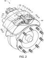
- a vehicle 10 in the form of a truck for which a wheel brake arrangement 100 according to the present disclosure is particularly suitable for.
- the vehicle 100 comprises a pair of front wheels 12 and a pair of rear wheels 14.
- the vehicle may also comprise further pair of wheels as well.
- the front pair of wheels 12 comprises a wheel brake arrangement 100 arranged for controllably reducing the vehicle speed of the vehicle 10.
- the wheel brake arrangement 100 is operated by means of a controlling a brake pedal arranged in the vehicle compartment, or by means of a suitable control system.
- the rear wheels 14 may comprise a similar wheel brake arrangement 100 as the front wheels 12.
- the wheel brake arrangement 100 comprises a first brake pad arrangement 102 and a second brake pad arrangement 150, each comprising a respective brake pad 104, 104' as well as a respective backing plate 116, 116' arranged as a support for the brake pad.
- a brake disc 106 is arranged between the first 102 and second 150 brake pad arrangements. The brake disc 106 is connected to a wheel (not shown) of the vehicle whereby the wheel brake arrangement 100 is arranged to controllably reduce the rotational speed of the wheel during operation of the vehicle 10.
- the wheel brake arrangement 100 further comprises a caliper 108 at least partially housing the brake pad arrangements 102, 150, as well as the brake disc 106.
- the caliper 108 comprises a first caliper part 108' and a second caliper part 108" which are connected to each other.
- the first 108' and second 108" caliper parts form an opening 111 of the caliper 108. By means of the opening 111, components of the brake pad arrangement are accessible whereby maintenance thereof is simplified.
- the wheel brake arrangement 100 comprises a retainer bar 110.
- the retainer bar 110 is connected between the first 108' and second 108" caliper parts.
- the retainer bar 110 is connected to the second caliper part 108" by means of a screw connection and extends axially across each of the first 102 and second 150 brake pad arrangements, as well as the brake disc 106, thus forming a bridge radially above the opening 111.
- the width, i.e. the extension perpendicular to the axial direction of the wheel brake arrangement, of the retainer bar 110 is smaller in the vicinity of the first brake pad arrangement 102 in comparison to the width in the vicinity of the second brake pad arrangement 150.
- the retainer bar 110 preferably comprises an increased thickness at the position above the backing plate 116 of the first brake pad arrangement 102.
- the increased thickness reduces the risk of assembling the wheel brake arrangement 100 incorrectly.
- the wheel brake arrangement 100 further comprises a resilient member 114, in the following referred to as a resilient spring 114.
- the resilient spring 114 is connected between the first brake pad arrangement 102 and the retainer bar 110.
- the resilient spring 114 comprises a loop portion 136 through which a connecting member 138, here in the form of a screw is connecting the resilient spring 114 to the backing plate 116 of the second brake pad arrangement 102.
- the resilient spring 114 is thus connected to a second surface 120 of the backing plate 116 which second surface 120 faces away from the first brake pad 104, as well as the brake disc 106.
- the resilient spring 114 comprises a first 122 and a second 124 spring leg, which are arranged in a V-shaped configuration.
- the loop portion 136 is thus arranged below the V-shape of the resilient spring 114.
- the first 122 and second 124 spring legs are connected to a first 126 and a second 128 axially extending side surface of the retainer bar, respectively.
- the first 126 and second 128 axially extending side surfaces of the retainer bar 110 each has a surface normal perpendicular to a surface normal facing the brake pad arrangement 102 and brake disc 106.
- the V-shaped resilient spring 114 is connected to the retainer bar 110 by means of a pre-tension urging the first 122 and second 124 legs in a direction towards each other.
- a compression force is generated between the first leg 122 and the first axially extending side surface 126 of the retainer bar 110, as well as between the second leg 124 and the second axially extending side surface 128 of the retainer bar 110.
- the first 126 and second 128 axially extending side surfaces comprise a respective recess 130, 132 at the interface connecting with the first 122 and second 124 legs.
- the wheel brake arrangement 100 comprises a pad holding spring 302 connected to the backing plate 116' of the second brake pad arrangement 150.
- the pad holding spring 302 is thus arranged on an opposite axial side of the brake disc 106 compared to the position of the resilient spring 114.
- the pad holding spring 302 is connected to the backing plate 116' of the second brake pad arrangement 150 by means of two radially extending protruding portions 304 on the upper surface of the backing plate 116'. These protruding portions 304 are arranged in a respective opening 306 of the pad holding spring 302.
- the pad holding spring 302 comprises a surface portion 306 having a surface normal facing away from the backing plate 116'.
- the surface portion 306 of the pad holding spring 302 is arranged in contact with the retainer bar 110.
- the retainer bar 110 and the pad holding spring 302 prevent a radially extending motion of the second brake pad arrangement 150.
- Fig. 4 illustrates the wheel brake arrangement 100 in a non-braking state where the wheel is free to rotate
- Fig. 5 illustrates the wheel brake arrangement 100 in a braking state where the wheel is substantially prevented from rotating.
- the brake pad arrangement 102 is not actuated and there is a gap 402 between the first brake pad 104 and the brake 106 such that the wheel is free to rotate.
- the resilient member 114 is, as described above, connected between the backing plate 116 of first brake pad arrangement 102 and the retainer bar 110. In detail, when the brake is not actuated as illustrated in Fig. 4 , there is no, or a small, axial tension in the resilient member 114.
- the brake pad 104 of the first brake pad arrangement 102 is arranged in connection with the brake disc 106 such that the brake pad 104 presses against the brake disc 106 for generating a braking torque.
- the resilient spring 114 has moved the axial distance 402 depicted in Fig. 4 .
- An increased axial tension F ax in the resilient spring 114 has hereby been generated.
- a tension F ax in the axial direction away from the brake disc 106 is generated in the resilient spring when applying the brake using e.g. a brake cylinder or other actuating means.
- the axial tension F ax will urge the first brake pad arrangement 102 in the axial direction away from the brake disc when releasing the brake.
- the resilient spring 114 is arranged in the above described V-shape, a force component in the radial direction is also generated when connecting the resilient spring between the first brake pad arrangement 102 and the retainer bar 110.
- the resilient spring 114 also serves the function of preventing a radial motion of the first brake pad arrangement 102 similar to the functionalities described for the above pad holding spring 302.
- the pad holding spring 302 connected to the second brake pad arrangement 150 may be replaced by a resilient spring 114 similar to the one connected between the first brake pad arrangement 102 and the retainer bar 110.
Landscapes
- Engineering & Computer Science (AREA)
- General Engineering & Computer Science (AREA)
- Mechanical Engineering (AREA)
- Transportation (AREA)
- Braking Arrangements (AREA)
Abstract
Description
- The present disclosure relates to a wheel brake arrangement. The wheel brake arrangement is applicable on vehicles, in particularly low, medium and heavy duty vehicles commonly referred to as trucks. Although the wheel brake arrangement will mainly be described in relation to a truck, it may also be applicable for other types of vehicles comprising wheel brakes in the form of disc brakes.
- In connection to vehicles in the form trucks, also known as low-, medium and heavy duty vehicles, there is always a high demand on the wheel brakes. These demands relate in particular to the braking capability of the wheel brake as they need to function properly in order to reduce vehicle speed properly.
- Typically, the wheel brake comprises a brake disc connected to a wheel hub, which in turn is connected to a wheel of the vehicle. The wheel brake further comprises brake pads which are arranged to provide a brake action against the brake disc, i.e. clamp against the brake disc, such that a rotation speed of the wheel is reduced. The brake disc will thus slip against the brake pads until the wheel has stopped its motion. This creates frictional heat in the brake disc which needs to be taken care of. The brake pads are in turn connected to a carrier arranged to support the brake pad and keep it in its correct position.
-
US 2016/0160945 describes a brake disc arrangement comprising a brake disc and two brake pads arranged on opposite sides of the brake disc for providing a braking action thereof. In particular,US 2016/0160945 describes the use of a pad holding spring which is arranged to prevent the brake pad from being twisted during operation. The pad holding spring is thus arranged to prevent a radial movement of the brake pad, and is spanned centrally by a pad holding bracket, which pad holding bracket extends axially with respect to the axis of rotation of the brake disc. - However, with the brake disc arrangement in
US 2016/0160945 , there is a risk that the brake pads are not sufficiently removed from the brake disc after a braking event, which may cause drag losses increasing the fuel consumption, and increased wear of the brake pads. There is thus a desire to improve the brake disc arrangement for e.g. increasing the operational life time of its components as well as reducing the fuel consumption generated by the drag losses. - It is an object of the present disclosure to provide a wheel brake arrangement which at least partially overcomes the above described deficiencies. This is achieved by a wheel brake arrangement according to claim 1.
- According to a first aspect, there is provided a wheel brake arrangement for a wheel of a vehicle, the wheel brake arrangement comprising a brake pad arrangement comprising a brake pad; a brake disc connectable to a wheel of the vehicle for reducing the speed of the vehicle when the brake pad is pressed against the brake disc; a caliper, at least partially housing the brake pad arrangement and the brake disc; and a retainer bar connected to the caliper, the retainer bar extending across the brake pad arrangement and the brake disc in an axial direction of the wheel brake arrangement, wherein the retainer bar is disconnectable from the caliper; wherein the wheel brake arrangement further comprises a resilient member connected to the brake pad arrangement and to the retainer bar, the resilient member being tensioned when the brake pad is pressed against the brake disc for urging the brake pad arrangement in a direction axially away from the brake disc when releasing the brake pad from the brake disc.
- The wording "caliper" should be understood to mean a structure of the braking arrangement that forms a housing for the components of the braking arrangement. Preferably, the caliper comprises an opening at an upper portion for simplifying maintenance of e.g. the brake disc and brake pad arrangement, etc. Also, the retainer bar may be arranged to extend across the opening at the upper portion. The retainer bar is thus preferably extending across the brake pad arrangement and the brake disc at a position radially outside the brake pad arrangement and the brake disc. The retainer bar may preferably be disconnectable from the caliper by means of e.g. a screw connection. The retainer bar may also be pivotably connected to the caliper, connected to the caliper via another attachments device, such as e.g. a bracket, etc. The retainer bar is preferably arranged as a radial support for a pad holding spring arranged on an opposite side of the brake disc in comparison to the position of the resilient member. Such pad holding spring is arranged to prevent a second brake pad arrangement, to which the pad holding spring is connected, from being twisted out during operation. The second brake pad arrangement is thus arranged on the opposite side of the brake disc in comparison to the brake pad arrangement to which the resilient member is connected.
- An advantage of the resilient member of the present disclosure is that the brake pad arrangement can be quickly returned to its non-activated position when the braking action is finished, i.e. when a braking action is no longer needed. Hereby, the risk of so-called drag losses, i.e. when the brake pad slips against the brake disc after releasing the brake, is reduced. As such, wear of the wheel brake arrangement is reduced. Also, a reduction of drag losses will also reduce the fuel consumption as less inertia for rotating the wheel is achieved.
- Moreover, the resilient member may also have the secondary function of preventing the brake pad arrangement from moving radially out of the wheel brake arrangement. Hence, a radial force component is present between the resilient member and the retainer bar. As such, the resilient member fulfils also the function of a conventional pad holding spring. A still further advantage is that rattling noise from the brake is reduced.
- According to an example embodiment, the brake pad arrangement may comprise a backing plate, the brake pad being connected to a first surface of the backing plate, wherein the resilient member is connected to a second surface of the backing plate, the second surface facing away from the brake pad.
- The backing plate, also referred to as a back plate, serves the function of supporting the brake pad.
- According to an example embodiment, the resilient member may be a resilient spring, the resilient spring comprising a first and a second spring leg arranged in a V-shaped configuration, wherein the first and second legs are connected to a first and second axially extending side surfaces of the retainer bar, respectively.
- Hence, the outer end portions of the respective leg are arranged in the vicinity of the retainer bar. Thus, the inner portion of the V-shaped resilient spring is connected to the brake pad arrangement. Furthermore, the axially extending side surfaces of the retainer bar should be understood to extend in a direction across the brake pad arrangement and brake disc.
- According to an example embodiment, the first and second axially extending side surfaces may each comprise a surface normal being perpendicular to a surface normal of the retainer bar facing the brake pad arrangement and brake disc. Thus, the resilient spring is connected to side surfaces of the retainer bar.
- According to an example embodiment, the resilient spring may be connected to the first and second axially extending side surfaces by a pre-tension for urging the first and second spring legs in a direction towards each other.
- The pre-tension of the resilient spring should be understood such that a distance between portions of the legs when not connected to the retainer bar is smaller than a width of the retainer bar. Thus, in order to attach the resilient spring to the retainer bar, the resilient spring needs to be exposed to an external force increasing the distance between the legs of the V-shape. An advantage of providing the resilient spring in a pre-tensioned state is that an improved connection to the retainer bar is achieved.
- According to an example embodiment, the retainer bar may comprise a recess in each of the first and second axially extending side surfaces, wherein the first and second spring legs are positioned in the respective recess. Hereby, axial displacement of the resilient spring is substantially prevented.
- According to an example embodiment, the resilient member may comprise a loop portion arranged at a lower end portion of the resilient member, the resilient member being connected to the brake pad arrangement by means of a connecting member connected through the loop portion and into the brake pad arrangement.
- The connecting member may preferably be a screw or bolt which is connected through the loop portion and connected to the brake pad arrangement.
- According to an example embodiment, the loop portion may comprise a radially extending oval shape. Using a radially extending loop portion will simplify the adjustment of the resilient member when connecting the resilient member to the brake pad arrangement and the retainer bar.
- According to an example embodiment, a width of the retainer bar may be smaller at the position connecting with the resilient member compared to a width of the retainer bar at a position axially opposite the brake disc.
- Hereby, at least a portion of the retainer bar is more or less arranged in a tapered shape or equivalent, where the width of the retainer bar is decreasing in a direction towards the position of the resilient member. The retainer bar may of course have a relatively uniform width at a first portion across the brake pad arrangement and brake disc, and thereafter, at a second portion decrease in width. An advantage is that there is a reduced risk of tensioning the resilient member in the "wrong" axial direction. Hence, it is further assured that the resilient member will urge the brake bad away from the brake disc when releasing the brake.
- According to an example embodiment, the retainer bar may be arranged radially above, and at a circumferentially central position in relation to the brake pad arrangement. Hereby, also the resilient member is arranged at the circumferential central position which will enable for a uniform load distribution on the brake pad arrangement. Hence, the risk of twisting the brake pad arrangement when releasing the brake is reduced.
- According to an example embodiment, the retainer bar may be connected to the caliper by means of at least one screw connection element.
- According to an example embodiment, the brake pad arrangement may be a first brake pad arrangement, wherein the wheel brake arrangement further comprises a second brake pad arrangement arranged at an axially opposite positon of the brake disc compared to the first brake pad arrangement. The second brake pad arrangement may preferably be non-actuatable, i.e. there is no piston or the like forcing the second brake pad arrangement towards the brake disc during a braking action. The second brake pad arrangement naturally forms a counter part during braking, i.e. the first brake pad arrangement is pressed against the brake disc during braking, whereby the brake disc will be pressed against the second brake pad arrangement. The wheel brake arrangement is thus a so-called floating caliper type brake.
- Moreover, the second brake pad arrangement may preferably comprise a pad holding spring as described above.
- According to an example embodiment, the caliper may comprise a first caliper part and a second caliper part, the first and second caliper parts comprises a respective portion arranged on a respective axial side of the brake pad arrangement and the brake disc. The first and second caliper parts may thus form the above described opening. The caliper is thus a two-part caliper.
- According to an example embodiment, the retainer bar may be connected between the first and second caliper parts. The retainer bar is thus arranged across the opening formed by the first and second caliper parts.
- According to a second aspect, there is provided a vehicle comprising a wheel and a wheel brake arrangement according to any one of the embodiments described in relation to the first aspect, wherein the wheel brake arrangement is connected to the wheel.
- Effects and features of the second aspect are largely analogous to those described above in relation to the first aspect.
- Further features of, and advantages with, the present invention will become apparent when studying the appended claims and the following description. The skilled person will realize that different features of the present invention may be combined to create embodiments other than those described in the following, without departing from the scope of the present invention.
- The above, as well as additional objects, features and advantages, will be better understood through the following illustrative and non-limiting detailed description of exemplary embodiments, wherein:
-
Fig. 1 is a lateral side view illustrating an example embodiment of a vehicle in the form of a truck; -
Fig. 2 is a perspective view of a wheel brake arrangement according to an example embodiment; -
Fig. 3 is an exploded view illustrating components of the wheel brake arrangement ofFig. 2 in further detail; -
Fig. 4 is a cross section illustrating the wheel brake arrangement according to an example embodiment when not exposing the wheel to a braking action; and -
Fig. 5 is a cross section illustrating the wheel brake arrangement according to an example embodiment when exposing the wheel to a braking action. - The present disclosure will now be described more fully hereinafter with reference to the accompanying drawings, in which exemplary embodiments of the disclosure are shown. The disclosure may, however, be embodied in many different forms and should not be construed as limited to the embodiments set forth herein; rather, these embodiments are provided for thoroughness and completeness. Like reference character refer to like elements throughout the description.
- With particular reference to
Fig. 1 , there is provided avehicle 10 in the form of a truck for which awheel brake arrangement 100 according to the present disclosure is particularly suitable for. Thevehicle 100 comprises a pair offront wheels 12 and a pair ofrear wheels 14. Although not depicted inFig. 1 , the vehicle may also comprise further pair of wheels as well. Moreover, as depicted, the front pair ofwheels 12 comprises awheel brake arrangement 100 arranged for controllably reducing the vehicle speed of thevehicle 10. Thewheel brake arrangement 100 is operated by means of a controlling a brake pedal arranged in the vehicle compartment, or by means of a suitable control system. Although not depicted, also therear wheels 14 may comprise a similarwheel brake arrangement 100 as thefront wheels 12. - In order to describe the wheel brake arrangement in further detail, reference is made to
Figs 2 ― 5 which illustrate the wheel brake arrangement according to various example embodiments thereof. Firstly, with particular reference toFig. 1 in combination withFig.2 , thewheel brake arrangement 100 comprises a firstbrake pad arrangement 102 and a secondbrake pad arrangement 150, each comprising arespective brake pad 104, 104' as well as arespective backing plate 116, 116' arranged as a support for the brake pad. Moreover, abrake disc 106 is arranged between the first 102 and second 150 brake pad arrangements. Thebrake disc 106 is connected to a wheel (not shown) of the vehicle whereby thewheel brake arrangement 100 is arranged to controllably reduce the rotational speed of the wheel during operation of thevehicle 10. - Moreover, the
wheel brake arrangement 100 further comprises acaliper 108 at least partially housing thebrake pad arrangements brake disc 106. As can be seen, thecaliper 108 comprises a first caliper part 108' and asecond caliper part 108" which are connected to each other. Also, the first 108' and second 108" caliper parts form an opening 111 of thecaliper 108. By means of the opening 111, components of the brake pad arrangement are accessible whereby maintenance thereof is simplified. - Furthermore, the
wheel brake arrangement 100 comprises aretainer bar 110. Theretainer bar 110 is connected between the first 108' and second 108" caliper parts. In detail, theretainer bar 110 is connected to thesecond caliper part 108" by means of a screw connection and extends axially across each of the first 102 and second 150 brake pad arrangements, as well as thebrake disc 106, thus forming a bridge radially above the opening 111. As is further depicted inFig. 2 , the width, i.e. the extension perpendicular to the axial direction of the wheel brake arrangement, of theretainer bar 110 is smaller in the vicinity of the firstbrake pad arrangement 102 in comparison to the width in the vicinity of the secondbrake pad arrangement 150. Moreover, as indicated inFig. 4 , theretainer bar 110 preferably comprises an increased thickness at the position above thebacking plate 116 of the firstbrake pad arrangement 102. Preferably, the increased thickness reduces the risk of assembling thewheel brake arrangement 100 incorrectly. - The
wheel brake arrangement 100 further comprises aresilient member 114, in the following referred to as aresilient spring 114. Theresilient spring 114 is connected between the firstbrake pad arrangement 102 and theretainer bar 110. In the example embodiment depicted inFigs. 2 and3 , theresilient spring 114 comprises aloop portion 136 through which a connectingmember 138, here in the form of a screw is connecting theresilient spring 114 to thebacking plate 116 of the secondbrake pad arrangement 102. Theresilient spring 114 is thus connected to a second surface 120 of thebacking plate 116 which second surface 120 faces away from thefirst brake pad 104, as well as thebrake disc 106. - Moreover, the
resilient spring 114 comprises a first 122 and a second 124 spring leg, which are arranged in a V-shaped configuration. Theloop portion 136 is thus arranged below the V-shape of theresilient spring 114. The first 122 and second 124 spring legs are connected to a first 126 and a second 128 axially extending side surface of the retainer bar, respectively. As can be seen inFig. 2 , the first 126 and second 128 axially extending side surfaces of theretainer bar 110 each has a surface normal perpendicular to a surface normal facing thebrake pad arrangement 102 andbrake disc 106. Furthermore, the V-shapedresilient spring 114 is connected to theretainer bar 110 by means of a pre-tension urging the first 122 and second 124 legs in a direction towards each other. Thus, when connecting theresilient spring 114 to theretainer bar 110, a compression force is generated between thefirst leg 122 and the first axially extendingside surface 126 of theretainer bar 110, as well as between thesecond leg 124 and the second axially extending side surface 128 of theretainer bar 110. Moreover, the first 126 and second 128 axially extending side surfaces comprise arespective recess - Furthermore, the
wheel brake arrangement 100 comprises apad holding spring 302 connected to the backing plate 116' of the secondbrake pad arrangement 150. Thepad holding spring 302 is thus arranged on an opposite axial side of thebrake disc 106 compared to the position of theresilient spring 114. Thepad holding spring 302 is connected to the backing plate 116' of the secondbrake pad arrangement 150 by means of two radially extending protrudingportions 304 on the upper surface of the backing plate 116'. These protrudingportions 304 are arranged in arespective opening 306 of thepad holding spring 302. Furthermore, thepad holding spring 302 comprises asurface portion 306 having a surface normal facing away from the backing plate 116'. Thesurface portion 306 of thepad holding spring 302 is arranged in contact with theretainer bar 110. Hereby, theretainer bar 110 and thepad holding spring 302 prevent a radially extending motion of the secondbrake pad arrangement 150. - In order to describe the functionalities of the
resilient spring 114 in further detail, reference is made toFigs. 4 and5 .Fig. 4 illustrates thewheel brake arrangement 100 in a non-braking state where the wheel is free to rotate, whileFig. 5 illustrates thewheel brake arrangement 100 in a braking state where the wheel is substantially prevented from rotating. - Starting with
Fig. 4 , thebrake pad arrangement 102 is not actuated and there is agap 402 between thefirst brake pad 104 and thebrake 106 such that the wheel is free to rotate. Theresilient member 114 is, as described above, connected between thebacking plate 116 of firstbrake pad arrangement 102 and theretainer bar 110. In detail, when the brake is not actuated as illustrated inFig. 4 , there is no, or a small, axial tension in theresilient member 114. - When the
wheel brake arrangement 100 thereafter is actuated as depicted inFig. 5 , thebrake pad 104 of the firstbrake pad arrangement 102 is arranged in connection with thebrake disc 106 such that thebrake pad 104 presses against thebrake disc 106 for generating a braking torque. Hereby, theresilient spring 114 has moved theaxial distance 402 depicted inFig. 4 . An increased axial tension Fax in theresilient spring 114 has hereby been generated. In detail, a tension Fax in the axial direction away from thebrake disc 106 is generated in the resilient spring when applying the brake using e.g. a brake cylinder or other actuating means. The axial tension Fax will urge the firstbrake pad arrangement 102 in the axial direction away from the brake disc when releasing the brake. - Moreover, since the
resilient spring 114 is arranged in the above described V-shape, a force component in the radial direction is also generated when connecting the resilient spring between the firstbrake pad arrangement 102 and theretainer bar 110. Hereby, theresilient spring 114 also serves the function of preventing a radial motion of the firstbrake pad arrangement 102 similar to the functionalities described for the abovepad holding spring 302. - It is to be understood that the present invention is not limited to the embodiments described above and illustrated in the drawings; rather, the skilled person will recognize that many changes and modifications may be made within the scope of the appended claims. For example, the
pad holding spring 302 connected to the secondbrake pad arrangement 150 may be replaced by aresilient spring 114 similar to the one connected between the firstbrake pad arrangement 102 and theretainer bar 110.
Claims (15)
- A wheel brake arrangement (100), comprising:- a first brake pad arrangement (102) and a second brake pad arrangement (150), wherein the first brake pad arrangement (102) comprises a first backing plate (116) having a first surface arranged to support a first brake pad (104), and wherein the second brake pad arrangement (150) comprises a second backing plate (116') arranged to support a second brake pad (104'),- a pad holding spring (302) connected to the second brake pad arrangement for preventing radial displacement of the second brake pad arrangement,- a retainer bar (110) extending across the first (102) and second (150) brake pad arrangements in an axial direction of the wheel brake arrangement (100), wherein the retainer bar (110) is radially supporting the pad holding spring (302), and- a resilient member (114) connected to a second surface (120) of the first backing plate (116), the second surface (120) facing away from the first brake pad (104), wherein the resilient member (114) engages with the retainer bar (110) such that a radial force component is present between the resilient member and the retainer bar.
- The wheel brake arrangement (100) according to claim 1, wherein the resilient member is extending radially from the second surface of the first backing plate (116) to engage with the resilient member (114).
- The wheel brake arrangement (100) according to any one of claims 1 or 2, wherein the resilient member is a resilient spring comprising a first (122) and a second (124) spring leg.
- The wheel brake arrangement (100) according to claim 3, wherein each spring leg extends radially from the second surface of the first backing plate (116) to engage with the retainer bar (110).
- The wheel brake arrangement (100) according to any one of claims 3 or 4, wherein the first (122) and second (124) spring legs are arranged in a V-shaped configuration.
- The wheel brake arrangement (100) according to any one of the preceding claims, wherein the pad holding spring (302) is tangentially connected to the second brake pad arrangement.
- The wheel brake arrangement (100) according to any one of the preceding claims, wherein the second backing plate (116') comprises two radially extending protruding portions (304) on an upper surface of the second backing plate (116') connecting the pad holding spring (302) to the second backing plate (116').
- The wheel brake arrangement (100) according to claim 7, wherein the two protruding portions (304) are arranged in a respective opening (306) of the pad holding spring (302).
- The wheel brake arrangement (100) according to any one of the preceding claims, wherein the retainer bar (110) is arranged in a tapered shape with a decreasing width in a direction towards the position of the resilient spring.
- The wheel brake arrangement (100) according to any one of the preceding claims, wherein the retainer bar (110) comprises a first (126) and a second (128) axially extending side surface.
- The wheel brake arrangement (100) according to claim 10, wherein the retainer bar (110) comprises a recess (130, 132) in each of the first (126) and second (128) axially extending side surfaces.
- The wheel brake arrangement (100) according to claim 11, wherein the resilient member (114) engages with the retainer bar (110) at the recesses (130, 132) in the first (126) and second (128) axially extending side surfaces.
- The wheel brake arrangement according to any one of the preceding claims, wherein the retainer bar (110) comprises an increased thickness at a position radially above the first backing plate (116).
- The wheel brake arrangement according to any one of the preceding claims, wherein the resilient member (114) is tensioned when the brake pad (104) is pressed against the brake disc (106) for urging the brake pad arrangement (102) in a direction axially away from the brake disc (106) when releasing the brake pad (104) from the brake disc (106).
- A vehicle comprising a wheel and a wheel brake arrangement according to any one of the preceding claims, wherein the wheel brake arrangement is connected to the wheel.
Priority Applications (1)
| Application Number | Priority Date | Filing Date | Title |
|---|---|---|---|
| EP21201581.2A EP3957876B1 (en) | 2018-12-18 | 2018-12-18 | Brake pad arrangement |
Applications Claiming Priority (3)
| Application Number | Priority Date | Filing Date | Title |
|---|---|---|---|
| EP18830234.3A EP3899304B1 (en) | 2018-12-18 | 2018-12-18 | Wheel brake arrangement |
| PCT/EP2018/085599 WO2020125954A1 (en) | 2018-12-18 | 2018-12-18 | Wheel brake arrangement |
| EP21201581.2A EP3957876B1 (en) | 2018-12-18 | 2018-12-18 | Brake pad arrangement |
Related Parent Applications (3)
| Application Number | Title | Priority Date | Filing Date |
|---|---|---|---|
| EP18830234.3A Division EP3899304B1 (en) | 2018-12-18 | 2018-12-18 | Wheel brake arrangement |
| EP18830234.3A Division-Into EP3899304B1 (en) | 2018-12-18 | 2018-12-18 | Wheel brake arrangement |
| PCT/EP2018/085599 Previously-Filed-Application WO2020125954A1 (en) | 2018-12-18 | 2018-12-18 | Wheel brake arrangement |
Publications (3)
| Publication Number | Publication Date |
|---|---|
| EP3957876A1 true EP3957876A1 (en) | 2022-02-23 |
| EP3957876C0 EP3957876C0 (en) | 2023-06-07 |
| EP3957876B1 EP3957876B1 (en) | 2023-06-07 |
Family
ID=64959321
Family Applications (3)
| Application Number | Title | Priority Date | Filing Date |
|---|---|---|---|
| EP21201581.2A Active EP3957876B1 (en) | 2018-12-18 | 2018-12-18 | Brake pad arrangement |
| EP18830234.3A Active EP3899304B1 (en) | 2018-12-18 | 2018-12-18 | Wheel brake arrangement |
| EP21198610.4A Active EP3951207B1 (en) | 2018-12-18 | 2018-12-18 | Brake pad arrangement |
Family Applications After (2)
| Application Number | Title | Priority Date | Filing Date |
|---|---|---|---|
| EP18830234.3A Active EP3899304B1 (en) | 2018-12-18 | 2018-12-18 | Wheel brake arrangement |
| EP21198610.4A Active EP3951207B1 (en) | 2018-12-18 | 2018-12-18 | Brake pad arrangement |
Country Status (4)
| Country | Link |
|---|---|
| US (1) | US11971077B2 (en) |
| EP (3) | EP3957876B1 (en) |
| CN (3) | CN117605774A (en) |
| WO (1) | WO2020125954A1 (en) |
Families Citing this family (1)
| Publication number | Priority date | Publication date | Assignee | Title |
|---|---|---|---|---|
| EP4163512A1 (en) | 2021-10-06 | 2023-04-12 | MAT Commercial Vehicle Products GmbH | Brake pad |
Citations (3)
| Publication number | Priority date | Publication date | Assignee | Title |
|---|---|---|---|---|
| US4527669A (en) * | 1981-01-09 | 1985-07-09 | Lucas Industries Limited | Friction pad assemblies for use in disc brakes |
| DE102016120481A1 (en) * | 2016-10-27 | 2018-05-03 | Knorr-Bremse Systeme für Nutzfahrzeuge GmbH | Disc brake for a commercial vehicle and brake pad set |
| DE102016124310A1 (en) * | 2016-12-14 | 2018-06-14 | Knorr-Bremse Systeme für Nutzfahrzeuge GmbH | Disc brake for a commercial vehicle and brake pad set |
Family Cites Families (36)
| Publication number | Priority date | Publication date | Assignee | Title |
|---|---|---|---|---|
| DE3023103A1 (en) | 1979-06-20 | 1981-01-08 | Tokico Ltd | DISC BRAKE |
| DE3220632A1 (en) * | 1982-06-02 | 1983-12-08 | Alfred Teves Gmbh, 6000 Frankfurt | BRAKE SHOE ASSEMBLY |
| IT1227985B (en) * | 1988-01-07 | 1991-05-20 | Alfred Teves Gmbh F | DIVIDED GASKET DISC BRAKE |
| DE10046981A1 (en) * | 2000-09-22 | 2002-04-25 | Bosch Gmbh Robert | wheel brake |
| US6920965B2 (en) | 2000-10-18 | 2005-07-26 | Continental Teves Ag & Co. Ohg | Spot-type disc brake with a spring assembly for a brake pad |
| US7467693B2 (en) * | 2002-04-10 | 2008-12-23 | Akebono Corporation (North America) | Disc brake pad return spring |
| DE10351477B4 (en) * | 2003-11-04 | 2016-11-10 | Continental Teves Ag & Co. Ohg | Brake shoe assembly for a disc brake in particular a disc brake with floating caliper |
| FR2876427B1 (en) * | 2004-10-08 | 2008-03-14 | Bosch Gmbh Robert | FRICTION ELEMENT PROVIDED WITH RECALL MEANS AND DISC BRAKE COMPRISING SUCH A FRICTION ELEMENT |
| DE102005046804A1 (en) | 2005-01-18 | 2006-08-17 | Continental Teves Ag & Co. Ohg | Spot-type disc brake |
| DE102006058174A1 (en) * | 2006-12-09 | 2008-06-12 | Dr.Ing.H.C. F. Porsche Ag | Spring for a composite brake disc and composite brake disc |
| JP5292425B2 (en) * | 2010-04-09 | 2013-09-18 | 曙ブレーキ工業株式会社 | Floating disc brake, its assembling method, and assembly of pad clip and return spring |
| CN102011816B (en) * | 2010-12-01 | 2012-08-29 | 东风汽车有限公司 | Disc brake with friction block return structure |
| DE102013008155A1 (en) * | 2013-05-13 | 2014-11-13 | Wabco Europe Bvba | Caliper disc brake of a vehicle, in particular a commercial vehicle, and hold-down device such a brake |
| DE102013013686A1 (en) | 2013-08-16 | 2015-02-19 | Knorr-Bremse Systeme für Nutzfahrzeuge GmbH | Pad retaining spring of a brake pad and brake pad holder for a disc brake of a motor vehicle |
| FR3027081B1 (en) | 2014-10-10 | 2016-12-23 | Chassis Brakes Int Bv | "SLIDING CALIPER DISC BRAKE COMPRISING A CENTRAL SPRING OF ELASTIC RECALL OF AN EXTERNAL BRAKE SKATE COMPRISING MEANS OF RETRACTING THE WEAR SET, SPRING AND REPLACEMENT KIT" |
| EP3023666B2 (en) * | 2014-11-20 | 2022-09-14 | Meritor Heavy Vehicle Braking Systems (UK) Limited | Disc brake assembly |
| DE102016104970A1 (en) * | 2015-06-15 | 2016-12-15 | Knorr-Bremse Systeme für Nutzfahrzeuge GmbH | Disc brake for a commercial vehicle and brake pad set |
| DE102016104967A1 (en) * | 2015-10-09 | 2017-04-13 | Knorr-Bremse Systeme für Nutzfahrzeuge GmbH | brake carrier |
| US20170138426A1 (en) * | 2015-11-12 | 2017-05-18 | Bendix Spicer Foundation Brake Llc | Disc Brake and Set of Brake Pads |
| DE102016004516A1 (en) * | 2016-04-13 | 2017-10-19 | Wabco Europe Bvba | Disc brake, in particular for commercial vehicles |
| DE102016120478A1 (en) * | 2016-10-27 | 2018-05-03 | Knorr-Bremse Systeme für Nutzfahrzeuge GmbH | Disc brake for a commercial vehicle and brake pad for a disc brake |
| DE102017222639A1 (en) * | 2017-01-31 | 2018-08-02 | Continental Teves Ag & Co. Ohg | Fixed caliper motor vehicle tamper disc brake with a steel sheet bowing clearance spring |
| CN107178568B (en) * | 2017-07-12 | 2019-05-28 | 湖北航特科技有限责任公司 | Brake caliper assemblies and brake apparatus |
| DE102017007288A1 (en) * | 2017-08-01 | 2019-02-07 | Lucas Automotive Gmbh | Brake caliper assembly with pad resetting function |
| DE102017129672A1 (en) * | 2017-12-12 | 2019-06-13 | Knorr-Bremse Systeme für Nutzfahrzeuge GmbH | Disc brake for a commercial vehicle and brake pad set |
| US10968967B2 (en) * | 2018-11-12 | 2021-04-06 | Akebono Brake Industry Co., Ltd. | Brake retraction spring assembly |
| IT201800020401A1 (en) * | 2018-12-20 | 2020-06-20 | Freni Brembo Spa | PAD RETURN SPRING FOR A DISC BRAKE CALIPER BODY |
| US11143255B2 (en) * | 2019-05-09 | 2021-10-12 | Arvinmeritor Technology, Llc | Brake assembly having a retraction spring and method of assembly |
| US20210246952A1 (en) * | 2020-02-12 | 2021-08-12 | Arvinmeritor Technology, Llc | Brake assembly having a retraction spring |
| US20230108312A1 (en) * | 2020-02-20 | 2023-04-06 | Volvo Truck Corporation | Brake pad retainer system, brake pad, and vehicle |
| DE102020106296A1 (en) * | 2020-03-09 | 2021-09-23 | Tmd Friction Services Gmbh | Lining carrier plate for a disc brake of a motor vehicle and a method for its production |
| EP3954919A1 (en) * | 2020-08-11 | 2022-02-16 | Meritor Heavy Vehicle Braking Systems (UK) Limited | Brake assembly |
| US11649864B2 (en) * | 2021-06-11 | 2023-05-16 | Arvinmeritor Technology, Llc | Disc brake assembly having a sensor assembly attached to a retraction spring |
| DE102021121995A1 (en) * | 2021-08-25 | 2023-03-02 | Zf Cv Systems Europe Bv | Disc brake for a motor vehicle |
| IT202100025361A1 (en) * | 2021-10-04 | 2023-04-04 | Brembo Spa | Spring, spring and brake pad assembly, caliper body assembly |
| US20230265902A1 (en) * | 2022-02-21 | 2023-08-24 | Arvinmeritor Technology, Llc | Brake assembly having a sensor unit |
-
2018
- 2018-12-18 EP EP21201581.2A patent/EP3957876B1/en active Active
- 2018-12-18 CN CN202311482668.XA patent/CN117605774A/en active Pending
- 2018-12-18 CN CN202311478580.0A patent/CN117605773A/en active Pending
- 2018-12-18 CN CN201880100226.5A patent/CN113195919B/en active Active
- 2018-12-18 EP EP18830234.3A patent/EP3899304B1/en active Active
- 2018-12-18 US US17/416,231 patent/US11971077B2/en active Active
- 2018-12-18 EP EP21198610.4A patent/EP3951207B1/en active Active
- 2018-12-18 WO PCT/EP2018/085599 patent/WO2020125954A1/en unknown
Patent Citations (3)
| Publication number | Priority date | Publication date | Assignee | Title |
|---|---|---|---|---|
| US4527669A (en) * | 1981-01-09 | 1985-07-09 | Lucas Industries Limited | Friction pad assemblies for use in disc brakes |
| DE102016120481A1 (en) * | 2016-10-27 | 2018-05-03 | Knorr-Bremse Systeme für Nutzfahrzeuge GmbH | Disc brake for a commercial vehicle and brake pad set |
| DE102016124310A1 (en) * | 2016-12-14 | 2018-06-14 | Knorr-Bremse Systeme für Nutzfahrzeuge GmbH | Disc brake for a commercial vehicle and brake pad set |
Also Published As
| Publication number | Publication date |
|---|---|
| CN117605774A (en) | 2024-02-27 |
| CN113195919B (en) | 2023-11-14 |
| EP3899304C0 (en) | 2023-06-07 |
| US11971077B2 (en) | 2024-04-30 |
| EP3899304A1 (en) | 2021-10-27 |
| CN117605773A (en) | 2024-02-27 |
| EP3951207A1 (en) | 2022-02-09 |
| US20220074456A1 (en) | 2022-03-10 |
| EP3951207B1 (en) | 2023-01-18 |
| WO2020125954A1 (en) | 2020-06-25 |
| EP3957876C0 (en) | 2023-06-07 |
| CN113195919A (en) | 2021-07-30 |
| EP3957876B1 (en) | 2023-06-07 |
| EP3899304B1 (en) | 2023-06-07 |
Similar Documents
| Publication | Publication Date | Title |
|---|---|---|
| US7320386B2 (en) | High friction brake shoe assembly | |
| US6296085B1 (en) | Disk brake | |
| KR101990170B1 (en) | Pad retention system of a disc brake of a motor vehicle | |
| EP3899304B1 (en) | Wheel brake arrangement | |
| US5829555A (en) | Disc brake caliper assembly | |
| JP4880250B2 (en) | Vehicle disc brake | |
| EP0143170B1 (en) | Disc brake friction pad support and biasing assembly | |
| EP3746671B1 (en) | Wheel brake arrangement | |
| JP6483567B2 (en) | Electric parking brake | |
| EP4107405B1 (en) | Brake pad retainer system, brake pad and vehicle | |
| JPH09296836A (en) | Disc brake caliper | |
| JP2002168274A (en) | Drum brake | |
| JPH11201199A (en) | Disk brake | |
| GB2361969A (en) | Resilient mounting for an axially moveable brake disc | |
| CN117795224A (en) | Disc brake for a commercial vehicle and brake lining for a disc brake | |
| JP2002235779A (en) | Disc brake with parking mechanism | |
| JPH0122498B2 (en) | ||
| JPH11257385A (en) | Disk brake | |
| JPH11117959A (en) | Disc brake | |
| JP2002070898A (en) | Pin-slide type disc brake device | |
| KR20080024574A (en) | Dih parking brake system | |
| JP2000088016A (en) | Drum brake device |
Legal Events
| Date | Code | Title | Description |
|---|---|---|---|
| PUAI | Public reference made under article 153(3) epc to a published international application that has entered the european phase |
Free format text: ORIGINAL CODE: 0009012 |
|
| STAA | Information on the status of an ep patent application or granted ep patent |
Free format text: STATUS: THE APPLICATION HAS BEEN PUBLISHED |
|
| AC | Divisional application: reference to earlier application |
Ref document number: 3899304 Country of ref document: EP Kind code of ref document: P |
|
| AK | Designated contracting states |
Kind code of ref document: A1 Designated state(s): AL AT BE BG CH CY CZ DE DK EE ES FI FR GB GR HR HU IE IS IT LI LT LU LV MC MK MT NL NO PL PT RO RS SE SI SK SM TR |
|
| STAA | Information on the status of an ep patent application or granted ep patent |
Free format text: STATUS: REQUEST FOR EXAMINATION WAS MADE |
|
| 17P | Request for examination filed |
Effective date: 20220726 |
|
| RBV | Designated contracting states (corrected) |
Designated state(s): AL AT BE BG CH CY CZ DE DK EE ES FI FR GB GR HR HU IE IS IT LI LT LU LV MC MK MT NL NO PL PT RO RS SE SI SK SM TR |
|
| GRAP | Despatch of communication of intention to grant a patent |
Free format text: ORIGINAL CODE: EPIDOSNIGR1 |
|
| STAA | Information on the status of an ep patent application or granted ep patent |
Free format text: STATUS: GRANT OF PATENT IS INTENDED |
|
| INTG | Intention to grant announced |
Effective date: 20221103 |
|
| GRAS | Grant fee paid |
Free format text: ORIGINAL CODE: EPIDOSNIGR3 |
|
| GRAA | (expected) grant |
Free format text: ORIGINAL CODE: 0009210 |
|
| STAA | Information on the status of an ep patent application or granted ep patent |
Free format text: STATUS: THE PATENT HAS BEEN GRANTED |
|
| AC | Divisional application: reference to earlier application |
Ref document number: 3899304 Country of ref document: EP Kind code of ref document: P |
|
| AK | Designated contracting states |
Kind code of ref document: B1 Designated state(s): AL AT BE BG CH CY CZ DE DK EE ES FI FR GB GR HR HU IE IS IT LI LT LU LV MC MK MT NL NO PL PT RO RS SE SI SK SM TR |
|
| REG | Reference to a national code |
Ref country code: GB Ref legal event code: FG4D |
|
| REG | Reference to a national code |
Ref country code: CH Ref legal event code: EP Ref country code: AT Ref legal event code: REF Ref document number: 1575938 Country of ref document: AT Kind code of ref document: T Effective date: 20230615 |
|
| REG | Reference to a national code |
Ref country code: DE Ref legal event code: R096 Ref document number: 602018051747 Country of ref document: DE |
|
| U01 | Request for unitary effect filed |
Effective date: 20230607 |
|
| U07 | Unitary effect registered |
Designated state(s): AT BE BG DE DK EE FI FR IT LT LU LV MT NL PT SE SI Effective date: 20230612 |
|
| U1B | Unitary effect: place of business changed | ||
| REG | Reference to a national code |
Ref country code: LT Ref legal event code: MG9D |
|
| PG25 | Lapsed in a contracting state [announced via postgrant information from national office to epo] |
Ref country code: NO Free format text: LAPSE BECAUSE OF FAILURE TO SUBMIT A TRANSLATION OF THE DESCRIPTION OR TO PAY THE FEE WITHIN THE PRESCRIBED TIME-LIMIT Effective date: 20230907 Ref country code: ES Free format text: LAPSE BECAUSE OF FAILURE TO SUBMIT A TRANSLATION OF THE DESCRIPTION OR TO PAY THE FEE WITHIN THE PRESCRIBED TIME-LIMIT Effective date: 20230607 |
|
| PG25 | Lapsed in a contracting state [announced via postgrant information from national office to epo] |
Ref country code: RS Free format text: LAPSE BECAUSE OF FAILURE TO SUBMIT A TRANSLATION OF THE DESCRIPTION OR TO PAY THE FEE WITHIN THE PRESCRIBED TIME-LIMIT Effective date: 20230607 Ref country code: HR Free format text: LAPSE BECAUSE OF FAILURE TO SUBMIT A TRANSLATION OF THE DESCRIPTION OR TO PAY THE FEE WITHIN THE PRESCRIBED TIME-LIMIT Effective date: 20230607 Ref country code: GR Free format text: LAPSE BECAUSE OF FAILURE TO SUBMIT A TRANSLATION OF THE DESCRIPTION OR TO PAY THE FEE WITHIN THE PRESCRIBED TIME-LIMIT Effective date: 20230908 |
|
| PG25 | Lapsed in a contracting state [announced via postgrant information from national office to epo] |
Ref country code: SK Free format text: LAPSE BECAUSE OF FAILURE TO SUBMIT A TRANSLATION OF THE DESCRIPTION OR TO PAY THE FEE WITHIN THE PRESCRIBED TIME-LIMIT Effective date: 20230607 |
|
| PG25 | Lapsed in a contracting state [announced via postgrant information from national office to epo] |
Ref country code: IS Free format text: LAPSE BECAUSE OF FAILURE TO SUBMIT A TRANSLATION OF THE DESCRIPTION OR TO PAY THE FEE WITHIN THE PRESCRIBED TIME-LIMIT Effective date: 20231007 |
|
| PG25 | Lapsed in a contracting state [announced via postgrant information from national office to epo] |
Ref country code: SM Free format text: LAPSE BECAUSE OF FAILURE TO SUBMIT A TRANSLATION OF THE DESCRIPTION OR TO PAY THE FEE WITHIN THE PRESCRIBED TIME-LIMIT Effective date: 20230607 Ref country code: SK Free format text: LAPSE BECAUSE OF FAILURE TO SUBMIT A TRANSLATION OF THE DESCRIPTION OR TO PAY THE FEE WITHIN THE PRESCRIBED TIME-LIMIT Effective date: 20230607 Ref country code: RO Free format text: LAPSE BECAUSE OF FAILURE TO SUBMIT A TRANSLATION OF THE DESCRIPTION OR TO PAY THE FEE WITHIN THE PRESCRIBED TIME-LIMIT Effective date: 20230607 Ref country code: IS Free format text: LAPSE BECAUSE OF FAILURE TO SUBMIT A TRANSLATION OF THE DESCRIPTION OR TO PAY THE FEE WITHIN THE PRESCRIBED TIME-LIMIT Effective date: 20231007 Ref country code: CZ Free format text: LAPSE BECAUSE OF FAILURE TO SUBMIT A TRANSLATION OF THE DESCRIPTION OR TO PAY THE FEE WITHIN THE PRESCRIBED TIME-LIMIT Effective date: 20230607 |
|
| U20 | Renewal fee paid [unitary effect] |
Year of fee payment: 6 Effective date: 20231226 |
|
| PG25 | Lapsed in a contracting state [announced via postgrant information from national office to epo] |
Ref country code: PL Free format text: LAPSE BECAUSE OF FAILURE TO SUBMIT A TRANSLATION OF THE DESCRIPTION OR TO PAY THE FEE WITHIN THE PRESCRIBED TIME-LIMIT Effective date: 20230607 |
|
| REG | Reference to a national code |
Ref country code: DE Ref legal event code: R097 Ref document number: 602018051747 Country of ref document: DE |
|
| PLBE | No opposition filed within time limit |
Free format text: ORIGINAL CODE: 0009261 |
|
| STAA | Information on the status of an ep patent application or granted ep patent |
Free format text: STATUS: NO OPPOSITION FILED WITHIN TIME LIMIT |
|
| 26N | No opposition filed |
Effective date: 20240308 |