EP3957518A2 - Method and device for determining the position of an overhead line contact wire - Google Patents
Method and device for determining the position of an overhead line contact wire Download PDFInfo
- Publication number
- EP3957518A2 EP3957518A2 EP21191827.1A EP21191827A EP3957518A2 EP 3957518 A2 EP3957518 A2 EP 3957518A2 EP 21191827 A EP21191827 A EP 21191827A EP 3957518 A2 EP3957518 A2 EP 3957518A2
- Authority
- EP
- European Patent Office
- Prior art keywords
- contact wire
- rail
- offset
- measuring
- measuring device
- Prior art date
- Legal status (The legal status is an assumption and is not a legal conclusion. Google has not performed a legal analysis and makes no representation as to the accuracy of the status listed.)
- Pending
Links
Images


Classifications
-
- G—PHYSICS
- G01—MEASURING; TESTING
- G01B—MEASURING LENGTH, THICKNESS OR SIMILAR LINEAR DIMENSIONS; MEASURING ANGLES; MEASURING AREAS; MEASURING IRREGULARITIES OF SURFACES OR CONTOURS
- G01B11/00—Measuring arrangements characterised by the use of optical techniques
- G01B11/24—Measuring arrangements characterised by the use of optical techniques for measuring contours or curvatures
-
- B—PERFORMING OPERATIONS; TRANSPORTING
- B60—VEHICLES IN GENERAL
- B60M—POWER SUPPLY LINES, AND DEVICES ALONG RAILS, FOR ELECTRICALLY- PROPELLED VEHICLES
- B60M1/00—Power supply lines for contact with collector on vehicle
- B60M1/12—Trolley lines; Accessories therefor
- B60M1/28—Manufacturing or repairing trolley lines
-
- G—PHYSICS
- G01—MEASURING; TESTING
- G01B—MEASURING LENGTH, THICKNESS OR SIMILAR LINEAR DIMENSIONS; MEASURING ANGLES; MEASURING AREAS; MEASURING IRREGULARITIES OF SURFACES OR CONTOURS
- G01B11/00—Measuring arrangements characterised by the use of optical techniques
- G01B11/002—Measuring arrangements characterised by the use of optical techniques for measuring two or more coordinates
-
- G—PHYSICS
- G01—MEASURING; TESTING
- G01B—MEASURING LENGTH, THICKNESS OR SIMILAR LINEAR DIMENSIONS; MEASURING ANGLES; MEASURING AREAS; MEASURING IRREGULARITIES OF SURFACES OR CONTOURS
- G01B11/00—Measuring arrangements characterised by the use of optical techniques
- G01B11/24—Measuring arrangements characterised by the use of optical techniques for measuring contours or curvatures
- G01B11/245—Measuring arrangements characterised by the use of optical techniques for measuring contours or curvatures using a plurality of fixed, simultaneously operating transducers
-
- G—PHYSICS
- G01—MEASURING; TESTING
- G01S—RADIO DIRECTION-FINDING; RADIO NAVIGATION; DETERMINING DISTANCE OR VELOCITY BY USE OF RADIO WAVES; LOCATING OR PRESENCE-DETECTING BY USE OF THE REFLECTION OR RERADIATION OF RADIO WAVES; ANALOGOUS ARRANGEMENTS USING OTHER WAVES
- G01S17/00—Systems using the reflection or reradiation of electromagnetic waves other than radio waves, e.g. lidar systems
- G01S17/02—Systems using the reflection of electromagnetic waves other than radio waves
- G01S17/06—Systems determining position data of a target
- G01S17/42—Simultaneous measurement of distance and other co-ordinates
-
- G—PHYSICS
- G01—MEASURING; TESTING
- G01S—RADIO DIRECTION-FINDING; RADIO NAVIGATION; DETERMINING DISTANCE OR VELOCITY BY USE OF RADIO WAVES; LOCATING OR PRESENCE-DETECTING BY USE OF THE REFLECTION OR RERADIATION OF RADIO WAVES; ANALOGOUS ARRANGEMENTS USING OTHER WAVES
- G01S17/00—Systems using the reflection or reradiation of electromagnetic waves other than radio waves, e.g. lidar systems
- G01S17/88—Lidar systems specially adapted for specific applications
Definitions
- the present invention relates to a method and a device for determining the position of a contact wire for rail vehicles according to the independent patent claims.
- measuring devices are used to measure a number of parameters, it is usually necessary to coordinate the individual devices in a complex manner. In addition, the use of several measuring devices results in different sources of errors and defects.
- Static laser sources for example, are known in the prior art for determining the position of contact wires. However, these require an initial manual alignment of the laser beam to the contact wire, which can impede the workflow and lead to further sources of error.
- the lateral offset of the measuring carriage or the point of emission of the laser beam is, in particular, the distance between the center of the rail and the point of intersection of the normal between the point of emission and the plane of the rail. If necessary, the lateral offset of the measuring carriage or the point of emission of the laser beam is the horizontal distance between the point of emission and the center of the rail.
- the height offset of the measuring carriage or the point of emission of the laser beam is in particular the normal distance of the point of emission to the rail plane. If necessary, the height offset of the measuring carriage or the point of emission of the laser beam is the vertical distance between the point of emission and the plane of the rail.
- horizontal and vertical relate in particular to the rail plane as the reference plane.
- Horizontal means “parallel to the plane of the rails” where appropriate, and “vertical” means “orthogonal to the plane of the rails” where appropriate.
- the rail plane is formed in particular by the touching ends of the rail heads of two opposite rails.
- the straight line that connects the rail measuring points is preferably arranged parallel to the rail plane or it lies on the rail plane. If necessary, the rail measurement points can be at different positions on opposite rails. In this case, the connecting end of the two rail measurement points is not parallel to the plane of the rail. However, by knowing the position of the rail measurement points, the data processing system can be used to back-calculate the position of the rail plane.
- the contact wire height is in particular the normal distance between rail level and contact wire.
- the contact wire offset is in particular the vertical distance between the contact wire position and the center of the rail. If applicable, the contact wire offset is the Distance between the center of the rail and the intersection of the normal between the contact wire and the plane of the rail.
- the rail center is in particular the geometric center point between two rails.
- a rail measuring point is in particular a specific point on the outer profile of a rail.
- the two rail measuring points are preferably arranged at the same positions on opposite rails. In this case, a straight line running through the rail measurement points is essentially parallel to the plane of the rail. If necessary, the rail measuring points can also be arranged at different positions on opposite rails.
- the contact wire can be a live catenary, a carrying cable or any other wire or cable-like device.
- the contact wire is arranged above the rails.
- the method according to the invention may include determining the distance between the emission point and the contact wire, between the emission point and a first rail measurement point on a first rail, and between the emission point and a second rail measurement point on a second rail, with the second rail being arranged opposite the first rail.
- the method includes determining the rail plane by calculating a straight line that runs through the two rail measurement points.
- the measuring device is moved over the rails at a feed rate, and that the method steps are carried out and repeated continuously, so that a course of the contact wire offset and/or the contact wire height along the feed direction is obtained. This enables a continuous profile to be recorded.
- the transmission device emits a laser beam which rotates about an axis running along the feed direction.
- the propagation direction of the laser beam runs in particular essentially orthogonally to the feed direction and/or to the axis of rotation.
- the surroundings of the measuring device are scanned essentially in a circular manner.
- the advancement of the device results in a spiral-shaped scanning profile, it being possible to assume for simplification that all scanned points are located on a flat plane during a rotation of the laser beam.
- the parameters of rotational speed, feed rate and sampling rate or the number of measuring points per revolution can be adjusted accordingly.
- a specific angular range can be scanned by the rotating laser beam, so that the position of the contact wire is automatically detected. This means that no manual pre-positioning of the laser is required.
- the structural element can optionally be a support device, for example a support mast for the contact wire.
- the structural element can optionally be a wall of a structure, for example a tunnel wall.
- the construction element can optionally be a rail foundation, for example the profile of a railway embankment.
- the distance between the structural element and the contact wire is determined by means of the data processing system.
- the distance between the structural element and the contact wire is the horizontal distance between the structural element and the contact wire.
- the horizontal distance is in particular the distance between the contact wire and the closest point on the construction element in the horizontal direction.
- the distance between the structural element and the contact wire is a distance between a support mast and the contact wire. If necessary, it is provided that the distance between the structural element and the contact wire is a distance between a tunnel wall and the contact wire.
- a rail spacing is in particular the distance between two opposite rails.
- the distance between the rails can be determined in particular on the basis of the ratio between the emission point of the laser beam and the rail measurement points.
- the rail spacing is compared, if necessary, with a target rail spacing using the data processing system.
- a warning can be issued if a limit value is exceeded or not reached.
- the method also includes determining the inclination ⁇ of the rail plane by measuring the inclination of the measuring device, in particular with respect to a horizontal plane.
- rails are usually elevated and therefore have an inclination compared to a horizontal plane. This means that the rail plane has an angle of inclination to the horizontal plane. If the rail plane is inclined, the distance from the contact wire to the ground is usually smaller than the measured contact wire height. This deviation can be corrected if necessary by measuring the inclination.
- the measured inclination ⁇ of the rail plane is used to calculate the horizontal distance between the contact wire and a construction element.
- the measured contact wire height, the contact wire offset and the inclination ⁇ are used for this calculation.
- the distance of the intersection of the normal between the contact wire and a rail plane and a rail center optionally corrected by the lateral offset of the measuring device.
- the contact wire offset, the height offset and the distance and/or the position of the contact wire are used to calculate the contact wire height.
- measuring points possibly between 2 and 20, lying next to one another are averaged. If necessary, an arithmetic mean can be formed. If necessary, between 2 and 10 adjacent measuring points can be averaged.
- a collision point between a detected structural element and a vehicle profile is determined by the data processing system from the lateral offset and possibly the inclination ⁇ . This makes it possible to determine whether a rail vehicle with a specific external geometry can safely pass a measured rail section.
- the device also includes an inclination sensor.
- the transmission device comprises a laser source which is designed to emit a rotating laser beam.
- the direction of propagation of the laser beam runs essentially orthogonally to the axis of rotation.
- the device is arranged on a measuring carriage that can be moved over the rails manually or by a motor, or that the device can be arranged on a rail vehicle.
- the measuring carriage can form an independent measuring device. If the measuring device can be arranged on a rail vehicle, it can be attached to an existing vehicle, for example a wagon or a railcar, and is moved over the rails by this vehicle.
- the measuring device is guided on two rails.
- the receiving device is designed in particular to detect the spatial position and the distance of a point reflecting the laser beam.
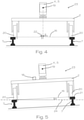
- a contact wire 1 shows a schematic front view of a measuring device 2 according to the invention on two opposite rails 7 according to a first embodiment.
- a contact wire 1 runs over the rails 7 or over the measuring device 2.
- the contact wire 1 is held by an element 13, which is designed as a support mast 14 in this example.
- FIG. 2 shows a detailed view of the measuring device 2 1 and 3 shows a side view of the measuring device 1 . Since the Figures 1-3 show the same embodiment, the elements shown are explained in a common description.
- the measuring device 2 is arranged on a measuring carriage 23 which comprises four wheels 20 which rest on the rails 7 or on the rail heads 21 .
- a transmitting device 4 and a receiving device 5 are carried by the measuring device 2 and are designed here as a common device.
- a data processing system (not shown) is also integrated into this facility Means for processing the measured data includes.
- the data processing system can be a computer, for example.
- the transmission device 4 is designed to emit a laser beam 3 .
- the laser beam 3 emerges from the transmission device 4 at an emission point 19 .
- the measuring device 2 is moved over the rails 7 along the feed direction 12 . This can be done manually or motor-driven.
- the laser beam 3 rotates about an axis that runs essentially parallel to the feed direction 12 . As a result, a spiral scanning surface is formed, which is continuously shifted by the movement of the measuring device 2 .
- the laser beam 3 If the laser beam 3 hits an opaque object, the light is reflected.
- the reflected laser beam 3 can be detected by the receiving device 5 . This makes it possible to determine the position and distance of points relative to the emission point 19 of the laser beam 3 .
- the positions of at least three points are recorded, namely the position of the contact wire, the position of a first rail measuring point 6' and the position of a second rail measuring point 6".
- the two rail measuring points 6', 6" are located on opposite rails 7 and correspond equivalent points on the two rails 7.
- the rail measuring points 6', 6" are the inner upper edges of the rail heads 21.
- the connecting end of the rail measuring points 6', 6" lies essentially on the rail level 16.
- connection between the two rail measurement points 6', 6" is on the rail plane 16. From the known distance between the rail measurement points 6', 6" and the measured distances between the emission point 19 and the rail measurement points 6', 6", both the lateral offset 8 and the Measuring device 2 and the height offset 9 of the measuring device 2 are determined.
- the lateral offset 8 is the distance between the center of the rail 22 and the intersection of the normal between rail plane 16 and the emission point 19 with the rail plane 16.
- the central axis 22 of the rails 7 is orthogonal to the rail plane 16.
- the lateral offset 8 is equal to zero and is therefore in 1 not shown.
- the side offset 8 is described below in connection with the second embodiment in 4 explained in detail.
- the height offset 9 is the normal distance between the emission point 19 and the rail level 16.
- the contact wire offset 10 can be determined.
- the contact wire offset 10 is the distance of the normal between the contact wire 1 and the rail plane 16 to the rail center 22. This value is usually corrected by the lateral offset 8, but this is not necessary in this case due to the missing lateral offset 8.
- the contact wire height 11 can be determined.
- the contact wire height 11 is the normal distance between the rail plane 16 and the contact wire 1 and can be calculated from the distance between the emission point 19 and the contact wire 1, the position of the contact wire 1 and the height offset 9 of the measuring device 2.
- the receiving device 5 can also be used to determine the position of other construction elements 13 along the rails 7 . For example, the position of the in 1 illustrated support mast 14 are determined.
- the contact wire 1 has a horizontal spacing 17 from the structural elements 13 .
- the rail spacing 27 is the distance between the two rails 7.
- FIG. 4 shows a detailed view of a measuring device 2 according to a second exemplary embodiment with lateral offset 8.
- the distance between the wheels 20 of the measuring carriage 23 is smaller than the distance between the two rails 7.
- the lateral offset 8 is the distance from the point of intersection of the normal between the rail plane 16 and the emission point 19 with the rail plane 16 to the middle of the rail 22.
- the lateral offset 8 can optionally vary along the course of the rails 7.
- FIG 5 shows a detailed view of a measuring device 2 according to a third exemplary embodiment with an inclination ⁇ of the rail plane 16.
- This rail section can be located, for example, in a curve in which the rails 7 are arranged at an elevated level.
- the measuring device 2 additionally includes an inclination sensor 18 which is designed to measure the inclination ⁇ of the measuring device 2 or of the measuring carriage 23 .
- the inclination ⁇ is determined relative to the horizontal plane 24 .
- the inclination ⁇ can be processed by the data processing system and used as a correction factor.
- the height of the contact wire above the ground can be determined from the contact wire height 11 and inclination ⁇ .
- FIG. 6 shows a detailed view of a measuring device 2 according to a fourth exemplary embodiment with additional detection of the profile 15 of a railway embankment.
- the measuring device 2 according to the invention is arranged on a measuring carriage 23 .
- the embodiments of the measuring device 2 described here can be arranged on an existing rail vehicle, for example a railcar.
- the data processing system can be arranged at a distance from the measuring device 2 .
- a data transmission device can be provided, which transmits the recorded data to the Data processing system transferred.
- the transmission can take place using conventional data transmission protocols, for example in wireless form.
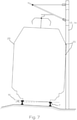
- FIG. 7 shows a schematic view of a rail section with a vehicle profile 26.
- collision points 25 with a structural element 13, in this example a support mast 14, are determined with a fixed vehicle profile 26 on the basis of the previously determined parameters inclination ⁇ and lateral offset.
- Different vehicle profiles 26 can be used as the vehicle profile 26, for example in the standard vehicle profile.
Abstract
Die Erfindung betrifft ein Verfahren zum Ermitteln der Lage eines Fahrdrahts (1) für Schienenfahrzeuge mit einer schienengeführten Messvorrichtung (2), umfassend:- Aussenden eines Laserstrahls (3) von einem Aussendepunkt (19) einer Sendeeinrichtung (4),- Messen der Reflexion des Laserstrahls (3) mit einer Empfangseinrichtung (5) und dadurch Erfassen einer Position des Fahrdrahts (1) sowie einer Position von wenigstens zwei Schienenmesspunkten (6', 6") auf gegenüberliegenden Schienen (7),- Einspeisen der erfassten Positionen in eine Datenverarbeitungsanlage und Ermitteln des Seitenversatzes (8) und/oder des Höhenversatzes (9) der Messvorrichtung (2) auf Basis der Position der Schienenmesspunkte (6', 6") und- Berechnen mittels der Datenverarbeitungsanlage des Fahrdrahtversatzes (10) und/oder der Fahrdrahthöhe (11) unter Verwendung des Seitenversatzes (8) und/oder des Höhenversatzes (9).Die Erfindung betrifft ferner eine Vorrichtung (2) zum Ermitteln der Lage eines Fahrdrahts (1).The invention relates to a method for determining the position of a contact wire (1) for rail vehicles using a rail-mounted measuring device (2), comprising: - emitting a laser beam (3) from an emitting point (19) of a transmitting device (4), - measuring the reflection of the laser beam (3) with a receiving device (5) and thereby detecting a position of the contact wire (1) and a position of at least two rail measuring points (6', 6") on opposite rails (7), - feeding the detected positions into a data processing system and Determining the lateral offset (8) and/or the vertical offset (9) of the measuring device (2) based on the position of the rail measuring points (6', 6") and calculating the contact wire offset (10) and/or the contact wire height (11 ) using the lateral offset (8) and/or the vertical offset (9). The invention also relates to a device (2) for determining the position of a contact wire (1).
Description
Die vorliegende Erfindung betrifft ein Verfahren und eine Vorrichtung zum Ermitteln der Lage eines Fahrdrahts für Schienenfahrzeuge gemäß den unabhängigen Patentansprüchen.The present invention relates to a method and a device for determining the position of a contact wire for rail vehicles according to the independent patent claims.
Im Stand der Technik sind unterschiedliche Verfahren zur Ermittlung der Lage eines Fahrdrahts bekannt. Derartige Verfahren und dazu geeignete Vorrichtungen werden eingesetzt, um die Höhe und die Seitenlage des Fahrdrahts von Schienenanlagen regelmäßig zu kontrollieren. Um eine möglichst genaue Bestimmung der relevanten Parameter des Fahrdrahts zu ermöglichen, müssen unterschiedliche Variablen in Betracht gezogen werden, zu deren Messung unterschiedliche Einrichtungen notwendig sind. Zu diesen Parametern zählen unter anderem der Seiten- und Höhenversatz der zur Messung eingesetzten Messvorrichtung.Various methods for determining the position of a contact wire are known in the prior art. Methods of this type and devices suitable for this purpose are used in order to regularly check the height and lateral position of the contact wire of rail systems. In order to enable the relevant parameters of the contact wire to be determined as accurately as possible, different variables must be taken into account, and different devices are required to measure them. These parameters include, among other things, the lateral and vertical offset of the measuring device used for the measurement.
Werden zur Messung mehrerer Parameter unterschiedliche Messeinrichtungen eingesetzt, ist üblicherweise eine aufwändige Abstimmung der einzelnen Einrichtungen aufeinander erforderlich. Überdies ergeben sich durch den Einsatz mehrerer Messeinrichtungen unterschiedliche Fehler- und Defektquellen.If different measuring devices are used to measure a number of parameters, it is usually necessary to coordinate the individual devices in a complex manner. In addition, the use of several measuring devices results in different sources of errors and defects.
Zur Bestimmung der Lage von Fahrdrähten sind im Stand der Technik beispielsweise statische Laserquellen bekannt. Diese machen jedoch eine anfängliche manuelle Ausrichtung des Laserstrahls auf den Fahrdraht erforderlich, was den Arbeitsfluss hemmen und zu weiteren Fehlerquellen führen kann.Static laser sources, for example, are known in the prior art for determining the position of contact wires. However, these require an initial manual alignment of the laser beam to the contact wire, which can impede the workflow and lead to further sources of error.
Es ist daher eine Aufgabe der vorliegenden Erfindung, die Nachteile des Standes der Technik zu überwinden und ein Verfahren und eine Vorrichtung zu schaffen, die in der Lage sind, mehrere zur Bestimmung von Fahrdrahtparametern erforderliche Parameter zu bestimmen und die bevorzugt keine manuelle Ausrichtung auf den Fahrdraht erfordert.It is therefore an object of the present invention to overcome the disadvantages of the prior art and to provide a method and apparatus which is capable of determining a plurality of parameters required for determining trolley wire parameters and which preferably does not require manual alignment with the trolley wire requires.
Diese Aufgabe wird durch ein Verfahren und eine Vorrichtung gemäß den unabhängigen Patentansprüchen gelöst.This object is achieved by a method and a device according to the independent patent claims.
Die vorliegende Erfindung betrifft ein Verfahren zum Ermitteln der Lage eines Fahrdrahts für Schienenfahrzeuge mit einer schienengeführten Messvorrichtung. Das Verfahren umfasst gegebenenfalls die folgenden Schritte:
- Aussenden eines Laserstrahls von einem Aussendepunkt einer Sendeeinrichtung,
- Messen der Reflexion des Laserstrahls mit einer Empfangseinrichtung und dadurch Erfassen einer Position des Fahrdrahts sowie einer Position von wenigstens zwei Schienenmesspunkten auf gegenüberliegenden Schienen,
- Einspeisen der erfassten Positionen in eine Datenverarbeitungsanlage und Ermitteln des Seitenversatzes und/oder des Höhenversatzes der Messvorrichtung auf Basis der Position der Schienenmesspunkte und
- Berechnen mittels der Datenverarbeitungsanlage des Fahrdrahtversatzes und/oder der Fahrdrahthöhe unter Verwendung des Seitenversatzes und/oder des Höhenversatzes.
- Emission of a laser beam from an emission point of a transmission device,
- Measuring the reflection of the laser beam with a receiving device and thereby detecting a position of the contact wire and a position of at least two rail measuring points on opposite rails,
- Feeding the recorded positions into a data processing system and determining the lateral offset and/or the vertical offset of the measuring device based on the position of the rail measuring points and
- Calculating the contact wire offset and/or the contact wire height using the lateral offset and/or the height offset using the data processing system.
Durch die Erfassung der Schienenmesspunkte und des Fahrdrahtes mit einer einzigen Sende- bzw. Empfangsvorrichtung wird die Anzahl der erforderlichen Messeinrichtungen reduziert. Die Berechnung der einzelnen Positionen zueinander ist insbesondere mit grundlegenden mathematischen Operationen über geometrische Zusammenhänge möglich.By capturing the rail measurement points and the contact wire with a single transmitting and receiving device, the number of measuring devices required is reduced. The calculation of the individual positions relative to one another is possible in particular with basic mathematical operations using geometric relationships.
Der Seitenversatz des Messwagens bzw. des Aussendepunkts des Laserstrahls ist insbesondere der Abstand zwischen der Schienenmitte und dem Schnittpunkt der Normalen zwischen dem Aussendepunkt und der Schienenebene. Gegebenenfalls ist der Seitenversatz des Messwagens bzw. des Aussendepunkts des Laserstrahls der horizontale Abstand zwischen Aussendepunkt und Schienenmitte.The lateral offset of the measuring carriage or the point of emission of the laser beam is, in particular, the distance between the center of the rail and the point of intersection of the normal between the point of emission and the plane of the rail. If necessary, the lateral offset of the measuring carriage or the point of emission of the laser beam is the horizontal distance between the point of emission and the center of the rail.
Der Höhenversatz des Messwagens bzw. des Aussendepunkts des Laserstrahls ist insbesondere der Normalabstand des Aussendepunkts zur Schienenebene. Gegebenenfalls ist der Höhenversatz des Messwagens bzw. des Aussendepunkts des Laserstrahls der vertikale Abstand zwischen Aussendepunkt und Schienenebene.The height offset of the measuring carriage or the point of emission of the laser beam is in particular the normal distance of the point of emission to the rail plane. If necessary, the height offset of the measuring carriage or the point of emission of the laser beam is the vertical distance between the point of emission and the plane of the rail.
Die Begriffe horizontal und vertikal beziehen sich in Zusammenhang mit dem Seiten- und Höhenversatz insbesondere auf die Schienenebene als Bezugsebene. "Horizontal" bedeutet gegebenenfalls "parallel zur Schienenebene" und "vertikal" bedeutet gegebenenfalls "orthogonal zur Schienenebene".In connection with the lateral and vertical offset, the terms horizontal and vertical relate in particular to the rail plane as the reference plane. "Horizontal" means "parallel to the plane of the rails" where appropriate, and "vertical" means "orthogonal to the plane of the rails" where appropriate.
Die Schienenebene ist insbesondere gebildet durch die Berührende der Schienenköpfe von zwei gegenüberliegenden Schienen.The rail plane is formed in particular by the touching ends of the rail heads of two opposite rails.
Bevorzugt ist die Gerade, die die Schienenmesspunkte verbindet parallel zur Schienenebene angeordnet oder sie liegt auf der Schienenebene. Gegebenenfalls können die Schienenmesspunkte an unterschiedlichen Positionen gegenüberliegender Schienen liegen. In diesem Fall ist die Verbindende der beiden Schienenmesspunkte nicht parallel zur Schienenebene. Durch Kenntnis der Position der Schienenmesspunkte kann jedoch mittels der Datenverarbeitungsanlage auf die Lage der Schienenebene rückgerechnet werden.The straight line that connects the rail measuring points is preferably arranged parallel to the rail plane or it lies on the rail plane. If necessary, the rail measurement points can be at different positions on opposite rails. In this case, the connecting end of the two rail measurement points is not parallel to the plane of the rail. However, by knowing the position of the rail measurement points, the data processing system can be used to back-calculate the position of the rail plane.
Die Fahrdrahthöhe ist insbesondere der Normalabstand zwischen Schienenebene und Fahrdraht.The contact wire height is in particular the normal distance between rail level and contact wire.
Der Fahrdrahtversatz ist insbesondere der vertikale Abstand zwischen der Fahrdrahtposition und der Schienenmitte. Gegebenenfalls ist der Fahrdrahtversatz der Abstand zwischen der Schienenmitte und dem Schnittpunkt der Normalen zwischen dem Fahrdraht und der Schienenebene.The contact wire offset is in particular the vertical distance between the contact wire position and the center of the rail. If applicable, the contact wire offset is the Distance between the center of the rail and the intersection of the normal between the contact wire and the plane of the rail.
Die Schienenmitte ist insbesondere der geometrische Mittelpunkt zwischen zwei Schienen.The rail center is in particular the geometric center point between two rails.
Ein Schienenmesspunkt ist insbesondere ein bestimmter Punkt am äußeren Profil einer Schiene. Bevorzugt sind die beiden Schienenmesspunkte an gleichen Positionen gegenüberliegender Schienen angeordnet. In diesem Fall ist eine durch die Schienenmesspunkte laufende Gerade im Wesentlichen parallel zur Schienenebene. Gegebenenfalls können die Schienenmesspunkte auch an unterschiedlichen Positionen gegenüberliegender Schienen angeordnet sein.A rail measuring point is in particular a specific point on the outer profile of a rail. The two rail measuring points are preferably arranged at the same positions on opposite rails. In this case, a straight line running through the rail measurement points is essentially parallel to the plane of the rail. If necessary, the rail measuring points can also be arranged at different positions on opposite rails.
Der Fahrdraht kann gegebenenfalls eine stromführende Oberleitung, ein Tragseil oder eine beliebige andere draht- oder seilförmige Einrichtung sein. Insbesondere ist der Fahrdraht über den Schienen angeordnet.Where appropriate, the contact wire can be a live catenary, a carrying cable or any other wire or cable-like device. In particular, the contact wire is arranged above the rails.
Gegebenenfalls umfasst das erfindungsgemäße Verfahren das Bestimmen des Abstands zwischen Aussendepunkt und Fahrdraht, zwischen Aussendepunkt und einem ersten Schienenmesspunkt auf einer ersten Schiene, und zwischen Aussendepunkt und einem zweiten Schienenmesspunkt auf einer zweiten Schiene, wobei die zweite Schiene der ersten Schiene gegenüberliegend angeordnet ist. Gegebenenfalls umfasst das Verfahren das Bestimmen der Schienenebene durch Berechnung einer Geraden, die durch die beiden Schienenmesspunkte verläuft.The method according to the invention may include determining the distance between the emission point and the contact wire, between the emission point and a first rail measurement point on a first rail, and between the emission point and a second rail measurement point on a second rail, with the second rail being arranged opposite the first rail. Optionally, the method includes determining the rail plane by calculating a straight line that runs through the two rail measurement points.
Gegebenenfalls ist vorgesehen, dass die Messvorrichtung mit einer Vorschubgeschwindigkeit über die Schienen bewegt wird, und dass die Verfahrensschritte kontinuierlich durchgeführt und wiederholt werden, sodass ein Verlauf des Fahrdrahtversatzes und/oder der Fahrdrahthöhe entlang der Vorschubrichtung erhalten wird. Dadurch wird die Aufzeichnung eines kontinuierlichen Profils möglich.If necessary, it is provided that the measuring device is moved over the rails at a feed rate, and that the method steps are carried out and repeated continuously, so that a course of the contact wire offset and/or the contact wire height along the feed direction is obtained. This enables a continuous profile to be recorded.
Gegebenenfalls ist vorgesehen, dass die Sendeeinrichtung einen Laserstrahl aussendet, der um eine entlang der Vorschubrichtung verlaufende Achse rotiert. Die Ausbreitungsrichtung des Laserstrahls verläuft dabei insbesondere im Wesentlichen orthogonal zur Vorschubrichtung und/oder zur Rotationsachse. Dadurch wird die Umgebung der Messvorrichtung im Wesentlichen kreisförmig abgetastet. Durch den Vorschub der Vorrichtung ergibt sich ein spiralförmiges Abtastprofil, wobei zur Vereinfachung angenommen werden kann, dass sich alle abgetasteten Punkte während einer Rotation des Laserstrahls auf einer planen Ebene befinden. Insbesondere können die Parameter Rotationsgeschwindigkeit, Vorschubgeschwindigkeit und Abtastrate bzw. Anzahl der Messpunkte pro Umdrehung entsprechend angepasst werden.If necessary, it is provided that the transmission device emits a laser beam which rotates about an axis running along the feed direction. the The propagation direction of the laser beam runs in particular essentially orthogonally to the feed direction and/or to the axis of rotation. As a result, the surroundings of the measuring device are scanned essentially in a circular manner. The advancement of the device results in a spiral-shaped scanning profile, it being possible to assume for simplification that all scanned points are located on a flat plane during a rotation of the laser beam. In particular, the parameters of rotational speed, feed rate and sampling rate or the number of measuring points per revolution can be adjusted accordingly.
Durch den rotierenden Laserstrahl kann ein bestimmter Winkelbereich abgerastert werden, sodass die Position des Fahrdrahts automatisch erkannt wird. Dadurch ist keine manuelle Vorpositionierung des Lasers erforderlich.A specific angular range can be scanned by the rotating laser beam, so that the position of the contact wire is automatically detected. This means that no manual pre-positioning of the laser is required.
Gegebenenfalls ist vorgesehen, dass durch das Messen der Reflexion des Laserstrahls mit der Empfangseinrichtung ferner eines oder mehrere Konstruktionselemente erfasst wird/werden. Das Konstruktionselement kann gegebenenfalls eine Stützeinrichtung, beispielsweise ein Tragmast des Fahrdrahts, sein. Das Konstruktionselement kann gegebenenfalls eine Wand einer baulichen Einrichtung, beispielsweise eine Tunnelwand, sein. Das Konstruktionselement kann gegebenenfalls ein Schienenfundament, beispielsweise das Profil eines Bahndamms, sein.If necessary, it is provided that by measuring the reflection of the laser beam with the receiving device, one or more construction elements is/are also detected. The structural element can optionally be a support device, for example a support mast for the contact wire. The structural element can optionally be a wall of a structure, for example a tunnel wall. The construction element can optionally be a rail foundation, for example the profile of a railway embankment.
Gegebenenfalls ist vorgesehen, dass mittels der Datenverarbeitungsanlage der Abstand zwischen dem Konstruktionselement und dem Fahrdraht bestimmt wird.If necessary, it is provided that the distance between the structural element and the contact wire is determined by means of the data processing system.
Gegebenenfalls ist vorgesehen, dass der Abstand zwischen dem Konstruktionselement und dem Fahrdraht der Horizontalabstand zwischen dem Konstruktionselement und dem Fahrdraht ist. Der Horizontalabstand ist insbesondere der Abstand zwischen dem Fahrdraht und dem nächstliegenden Punkt am Konstruktionselement in horizontaler Richtung.If necessary, it is provided that the distance between the structural element and the contact wire is the horizontal distance between the structural element and the contact wire. The horizontal distance is in particular the distance between the contact wire and the closest point on the construction element in the horizontal direction.
Gegebenenfalls ist vorgesehen, dass der Abstand zwischen dem Konstruktionselement und dem Fahrdraht ein Abstand zwischen einem Tragmast und dem Fahrdraht ist. Gegebenenfalls ist vorgesehen, dass der Abstand zwischen dem Konstruktionselement und dem Fahrdraht ein Abstand zwischen einer Tunnelwand und dem Fahrdraht ist.If necessary, it is provided that the distance between the structural element and the contact wire is a distance between a support mast and the contact wire. If necessary, it is provided that the distance between the structural element and the contact wire is a distance between a tunnel wall and the contact wire.
Gegebenenfalls ist vorgesehen, dass auf Basis der Position der zwei Schienenmesspunkte mittels der Datenverarbeitungsanlage ein Schienenabstand bestimmt wird. Der Schienenabstand ist insbesondere der Abstand zwischen zwei gegenüberliegenden Schienen. Der Schienenabstand kann insbesondere auf Basis des Verhältnisses zwischen Aussendepunkt des Laserstrahls und den Schienenmesspunkten bestimmt werden.If necessary, provision is made for a rail spacing to be determined using the data processing system on the basis of the position of the two rail measuring points. The rail spacing is in particular the distance between two opposite rails. The distance between the rails can be determined in particular on the basis of the ratio between the emission point of the laser beam and the rail measurement points.
Gegebenenfalls ist vorgesehen, dass der Schienenabstand mittels der Datenverarbeitungsanlage gegebenenfalls mit einem Soll-Schienenabstand verglichen wird. Bei Über- oder Unterschreiten eines Grenzwerts kann ein Warnhinweis ausgegeben werden.If necessary, provision is made for the rail spacing to be compared, if necessary, with a target rail spacing using the data processing system. A warning can be issued if a limit value is exceeded or not reached.
Gegebenenfalls ist vorgesehen, dass das Verfahren ferner das Bestimmen der Neigung α der Schienenebene durch Messen der Neigung der Messvorrichtung, insbesondere gegenüber einer Horizontalebene, umfasst. Besonders in Kurvenabschnitten sind Schienen üblicherweise überhöht und weisen dadurch eine Neigung im Vergleich zu einer Horizontalebene auf. Dies bedeutet, dass die Schienenebene einen Neigungswinkel zur Horizontalebene aufweist. Wenn die Schienenebene geneigt ist, ist der Abstand des Fahrdrahts zum Boden üblicherweise kleiner als die gemessene Fahrdrahthöhe. Durch Messung der Neigung kann diese Abweichung gegebenenfalls korrigiert werden.If necessary, it is provided that the method also includes determining the inclination α of the rail plane by measuring the inclination of the measuring device, in particular with respect to a horizontal plane. Especially in curved sections, rails are usually elevated and therefore have an inclination compared to a horizontal plane. This means that the rail plane has an angle of inclination to the horizontal plane. If the rail plane is inclined, the distance from the contact wire to the ground is usually smaller than the measured contact wire height. This deviation can be corrected if necessary by measuring the inclination.
Gegebenenfalls ist vorgesehen, dass die gemessene Neigung α der Schienenebene zum Berechnen des Horizontalabstands zwischen dem Fahrdraht und einem Konstruktionselement verwendet wird. Insbesondere werden für diese Berechnung die gemessene Fahrdrahthöhe, der Fahrdrahtversatz sowie die Neigung α verwendet.If necessary, it is provided that the measured inclination α of the rail plane is used to calculate the horizontal distance between the contact wire and a construction element. In particular, the measured contact wire height, the contact wire offset and the inclination α are used for this calculation.
Gegebenenfalls ist vorgesehen, dass zum Berechnen des Fahrdrahtversatzes der Abstand des Schnittpunkts der Normalen zwischen Fahrdraht und einer Schienenebene und einer Schienenmitte, gegebenenfalls korrigiert um den Seitenversatz der Messvorrichtung bestimmt wird.If necessary, it is provided that to calculate the contact wire offset, the distance of the intersection of the normal between the contact wire and a rail plane and a rail center, optionally corrected by the lateral offset of the measuring device.
Gegebenenfalls ist vorgesehen, dass zum Berechnen der Fahrdrahthöhe der Normalabstand zwischen dem Fahrdraht und einer Schienenebene, gegebenenfalls korrigiert um den Höhenversatz der Messvorrichtung, bestimmt wird. Gegebenenfalls wird zum Berechnen der Fahrdrahthöhe der Fahrdrahtversatz, der Höhenversatz und der Abstand und/oder die Position des Fahrdrahts verwendet.If necessary, provision is made for the normal distance between the contact wire and a rail plane, if necessary corrected by the height offset of the measuring device, to be determined in order to calculate the height of the contact wire. If necessary, the contact wire offset, the height offset and the distance and/or the position of the contact wire are used to calculate the contact wire height.
Gegebenenfalls ist vorgesehen, dass mehrere, gegebenenfalls zwischen 2 und 20, nebeneinander liegende Messpunkte gemittelt werden. Gegebenenfalls kann ein arithmetisches Mittel gebildet werden. Gegebenenfalls können zwischen 2 und 10 nebeneinander liegende Messpunkte gemittelt werden.If necessary, it is provided that several measuring points, possibly between 2 and 20, lying next to one another are averaged. If necessary, an arithmetic mean can be formed. If necessary, between 2 and 10 adjacent measuring points can be averaged.
Gegebenenfalls ist vorgesehen, dass durch die Datenverarbeitungsanlage aus dem Seitenversatz und gegebenenfalls der Neigung α ein Kollisionspunkt zwischen einem erfassten Konstruktionselement und einem Fahrzeugprofil ermittelt wird. Dadurch kann bestimmt werden, ob ein Schienenfahrzeug mit einer bestimmten Außengeometrie ungefährdet eine vermessene Schienenstrecke passieren kann.If necessary, it is provided that a collision point between a detected structural element and a vehicle profile is determined by the data processing system from the lateral offset and possibly the inclination α. This makes it possible to determine whether a rail vehicle with a specific external geometry can safely pass a measured rail section.
Gegebenenfalls betrifft die Erfindung eine Messvorrichtung zur Ausführung eines erfindungsgemäßen Verfahrens, wobei die Messvorrichtung eine Sendeeinrichtung, eine Empfangseinrichtung und eine Datenverarbeitungsanlage umfasst. Gegebenenfalls betrifft die Erfindung eine Messvorrichtung zum Ermitteln der Lage eines Fahrdrahts für Schienenfahrzeuge, wobei die Messvorrichtung schienengeführt ist und folgende Elemente umfasst:
- eine Sendeeinrichtung ausgebildet zum Aussenden eines Laserstrahls ausgehend von einem Aussendepunkt,
- eine Empfangseinrichtung ausgebildet zum Messen der Reflexion des Laserstrahls und zum Erfassen einer Position des Fahrdrahts sowie zum Erfassen einer Position von wenigstens zwei Schienenmesspunkten auf gegenüberliegenden Schienen,
- eine Datenverarbeitungsanlage ausgebildet zum Empfangen der erfassten Positionen sowie zum Ermitteln des Seitenversatzes und/oder des Höhenversatzes der Messvorrichtung auf Basis der Position der Schienenmesspunkte, und zum Berechnen des Fahrdrahtversatzes und/oder der Fahrdrahthöhe unter Verwendung des Seitenversatzes und/oder des Höhenversatzes.
- a transmission device designed to emit a laser beam starting from an emission point,
- a receiving device designed to measure the reflection of the laser beam and to detect a position of the contact wire and to detect a position of at least two rail measuring points on opposite rails,
- a data processing system designed to receive the detected positions and to determine the lateral offset and/or the vertical offset of the measuring device based on the position of the rail measuring points, and to calculate the contact wire offset and/or the contact wire height using the lateral offset and/or the vertical offset.
Gegebenenfalls ist vorgesehen, dass die Vorrichtung ferner einen Neigungssensor umfasst.If necessary, it is provided that the device also includes an inclination sensor.
Gegebenenfalls ist vorgesehen, dass die Sendeeinrichtung eine Laserquelle umfasst, die dazu ausgebildet ist, einen rotierenden Laserstrahl auszusenden. Insbesondere verläuft die Ausbreitungsrichtung des Laserstrahls im Wesentlichen orthogonal zur Rotationsachse.If necessary, it is provided that the transmission device comprises a laser source which is designed to emit a rotating laser beam. In particular, the direction of propagation of the laser beam runs essentially orthogonally to the axis of rotation.
Gegebenenfalls ist vorgesehen, dass die Vorrichtung an einem Messwagen angeordnet ist, der manuell oder motorgetrieben über die Schienen bewegbar ist, oder dass die Vorrichtung an einem Schienenfahrzeug anordenbar ist. Der Messwagen kann eine eigenständige Messvorrichtung bilden. Ist die Messvorrichtung an einem Schienenfahrzeug anordenbar, kann diese an einem bestehenden Fahrzeug, beispielsweise einem Waggon oder einem Triebwagen, angebracht werden und wird durch dieses Fahrzeug über die Schienen bewegt.If necessary, it is provided that the device is arranged on a measuring carriage that can be moved over the rails manually or by a motor, or that the device can be arranged on a rail vehicle. The measuring carriage can form an independent measuring device. If the measuring device can be arranged on a rail vehicle, it can be attached to an existing vehicle, for example a wagon or a railcar, and is moved over the rails by this vehicle.
Die Messvorrichtung ist insbesondere auf zwei Schienen geführt. Die Empfangseinrichtung ist insbesondere dazu ausgebildet, die räumliche Position und die Distanz eines den Laserstrahl reflektierenden Punktes zu erfassen.In particular, the measuring device is guided on two rails. The receiving device is designed in particular to detect the spatial position and the distance of a point reflecting the laser beam.
Weitere Merkmale der Erfindung ergeben sich aus der Beschreibung der Ausführungsbeispiele, den Figuren sowie aus den Patentansprüchen.Further features of the invention result from the description of the exemplary embodiments, the figures and the patent claims.
Nachfolgend wird die vorliegende Erfindung anhand von exemplarischen Ausführungsbeispielen im Detail erläutert. Diese Beispiele dienen lediglich der Veranschaulichung der Erfindung und sollen den Schutzbereich der Patentansprüche nicht einschränken.The present invention is explained in detail below using exemplary embodiments. These examples are only intended to illustrate the invention and are not intended to limit the scope of the claims.
-
Fig. 1 eine schematische Vorderansicht einer erfindungsgemäßen Messvorrichtung auf Schienen, angeordnet unter einem Fahrdraht gemäß einem ersten Ausführungsbeispiel,1 a schematic front view of a measuring device according to the invention on rails, arranged under a contact wire according to a first embodiment, -
Fig. 2 eine Detailansicht der Messvorrichtung ausFig. 1 ,2 a detailed view of the measuring device1 , -
Fig. 3 eine seitliche Ansicht der Messvorrichtung ausFig. 1 ,3 a side view of the measuring device1 , -
Fig. 4 eine Detailansicht einer Messvorrichtung gemäß einem zweiten Ausführungsbeispiel mit Seitenversatz,4 a detailed view of a measuring device according to a second embodiment with lateral offset, -
Fig. 5 eine Detailansicht einer Messvorrichtung gemäß einem dritten Ausführungsbeispiel mit Neigung,figure 5 a detailed view of a measuring device according to a third embodiment with inclination, -
Fig. 6 eine Detailansicht einer Messvorrichtung gemäß einem vierten Ausführungsbeispiel mit zusätzlicher Erfassung des Profils eines Bahndamms,6 a detailed view of a measuring device according to a fourth embodiment with additional detection of the profile of a railway embankment, -
Fig. 7 eine schematische Ansicht eines Schienenabschnitts mit einem Fahrzeugprofil gemäß einem fünften Ausführungsbeispiel.7 a schematic view of a rail section with a vehicle profile according to a fifth embodiment.
In allen Ausführungsbeispielen und Figuren bezeichnen gleiche Bezugszeichen gleiche Teile oder Elemente, sofern nicht anders angegeben.In all the exemplary embodiments and figures, the same reference symbols designate the same parts or elements, unless otherwise stated.
Die Messvorrichtung 2 ist auf einem Messwagen 23 angeordnet, der vier Räder 20 umfasst, die auf den Schienen 7 bzw. auf den Schienenköpfen 21 aufliegen. Von der Messvorrichtung 2 getragen werden eine Sendeeinrichtung 4 und eine Empfangseinrichtung 5, die hier als eine gemeinsame Einrichtung ausgeführt sind. In diese Einrichtung integriert ist ferner eine Datenverarbeitungsanlage (nicht gezeigt), die Mittel zur Verarbeitung der gemessenen Daten umfasst. Die Datenverarbeitungsanlage kann beispielsweise ein Computer sein.The measuring
Die Sendeeinrichtung 4 ist dazu ausgeführt einen Laserstrahl 3 auszusenden. Der Laserstrahl 3 tritt an einem Aussendepunkt 19 aus der Sendeeinrichtung 4 aus. Während der Messung wird die Messvorrichtung 2 entlang der Vorschubrichtung 12 über die Schienen 7 bewegt. Dies kann manuell oder motorgetrieben erfolgen. Der Laserstrahl 3 rotiert um eine Achse, die im Wesentlichen parallel zur Vorschubrichtung 12 verläuft. Dadurch wird eine spiralförmige Abtastfläche gebildet, die durch die Bewegung der Messvorrichtung 2 kontinuierlich verschoben wird.The transmission device 4 is designed to emit a
Trifft der Laserstrahl 3 auf einen lichtundurchlässigen Gegenstand, wird das Licht reflektiert. Der reflektierte Laserstahl 3 kann durch die Empfangseinrichtung 5 detektiert werden. Dadurch ist die Bestimmung der Lage und der Entfernung von Punkten relativ zum Aussendepunkt 19 des Laserstrahls 3 möglich.If the
In diesem Ausführungsbeispiel werden die Positionen von zumindest drei Punkten erfasst, nämlich der Position des Fahrdrahts, der Position eines ersten Schienenmesspunkts 6' und der Position eines zweiten Schienenmesspunkts 6". Die beiden Schienenmesspunkte 6', 6" befinden sich auf gegenüberliegenden Schienen 7 und entsprechen äquivalenten Punkten auf den beiden Schienen 7. In diesem Beispiel sind die Schienenmesspunkte 6', 6" jeweils die innenliegenden oberen Kanten der Schienenköpfe 21. Die Verbindende der Schienenmesspunkte 6', 6" liegt im Wesentlichen auf der Schienenebene 16.In this exemplary embodiment, the positions of at least three points are recorded, namely the position of the contact wire, the position of a first rail measuring point 6' and the position of a second
Die Verbindung der beiden Schienenmesspunkte 6', 6" liegt auf der Schienenebene 16. Aus dem bekannten Abstand zwischen den Schienenmesspunkten 6', 6" und den gemessenen Abständen zwischen dem Aussendepunkt 19 und den Schienenmesspunkten 6', 6" kann sowohl der Seitenversatz 8 der Messvorrichtung 2 als auch der Höhenversatz 9 der Messvorrichtung 2 bestimmt werden.The connection between the two
Der Seitenversatz 8 ist der Abstand zwischen der Schienenmitte 22 und dem Schnittpunkt der Normalen zwischen Schienenebene 16 und dem Aussendepunkt 19 mit der Schienenebene 16. Die Mittenachse 22 der Schienen 7 verläuft orthogonal zur Schienenebene 16. In diesem Ausführungsbeispiel ist der Seitenversatz 8 gleich null und ist daher in
Der Höhenversatz 9 ist der Normalabstand zwischen dem Aussendepunkt 19 und der Schienenebene 16.The height offset 9 is the normal distance between the
Nach Berechnung von Seitenversatz 8 und Höhenversatz 9 kann der Fahrdrahtversatz 10 bestimmt werden. Der Fahrdrahtversatz 10 ist der Abstand der Normalen zwischen dem Fahrdraht 1 und der Schienenebene 16 zur Schienenmitte 22. Üblicherweise wird dieser Wert um den Seitenversatz 8 korrigiert, was in diesem Fall jedoch aufgrund des fehlenden Seitenversatzes 8 nicht erforderlich ist.After calculating lateral offset 8 and vertical offset 9, the contact wire offset 10 can be determined. The contact wire offset 10 is the distance of the normal between the contact wire 1 and the
Ferner kann die Fahrdrahthöhe 11 bestimmt werden. Die Fahrdrahthöhe 11 ist der Normalabstand zwischen Schienenebene 16 und Fahrdraht 1 und kann aus dem Abstand zwischen Aussendepunkt 19 und dem Fahrdraht 1, der Position des Fahrdrahts 1 und dem Höhenversatz 9 der Messvorrichtung 2 berechnet werden.Furthermore, the
Wird die Messvorrichtung 2 kontinuierlich in einer Vorschubrichtung 12 über die Schienen 7 bewegt, kann ein Verlaufsprofil von Fahrdrahtversatz 10 und Fahrdrahthöhe 11 ermittelt werden.If the measuring
Die Empfangseinrichtung 5 kann ferner zur Ermittlung der Position weiterer Konstruktionselemente 13 entlang der Schienen 7 verwendet werden. Beispielsweise kann die Position des in
Der Fahrdraht 1 weist einen Horizontalabstand 17 zu den Konstruktionselementen 13 auf.The contact wire 1 has a
Der Schienenabstand 27 ist der Abstand zwischen den beiden Schienen 7.The
Die Neigung α kann von der Datenverarbeitungsanlage verarbeitet und als Korrekturfaktor verwendet werden. Beispielsweise kann aus Fahrdrahthöhe 11 und Neigung α die Höhe des Fahrdrahtes über dem Boden ermittelt werden.The inclination α can be processed by the data processing system and used as a correction factor. For example, the height of the contact wire above the ground can be determined from the
In allen hier beschriebenen Ausführungsbeispielen ist die erfindungsgemäße Messvorrichtung 2 auf einem Messwagen 23 angeordnet. In alternativen Ausführungsbeispielen können die hier beschriebenen Ausführungsformen der Messvorrichtung 2 auf einem bestehenden Schienenfahrzeug, beispielsweise einem Triebwagen, angeordnet sein.In all of the exemplary embodiments described here, the measuring
In einem nicht gezeigten Ausführungsbeispiel kann die Datenverarbeitungsanlage entfernt von der Messvorrichtung 2 angeordnet sein. In diesem Fall kann eine Datenübertragungseinrichtung vorgesehen sein, die die erfassten Daten an die Datenverarbeitungsanlage übertragt. Die Übertragung kann mit herkömmlichen Datenübertragungsprotokollen, beispielsweise in kabelloser Form, erfolgen.In an exemplary embodiment that is not shown, the data processing system can be arranged at a distance from the measuring
Als Fahrzeugprofil 26 können unterschiedliche Fahrzeugprofile 26 herangezogen werden, beispielsweise in Fahrzeug-Normprofil.Different vehicle profiles 26 can be used as the
- 11
- Fahrdrahtcontact wire
- 22
- Messvorrichtungmeasuring device
- 33
- Laserstrahllaser beam
- 44
- Sendeeinrichtungtransmission device
- 55
- Empfangseinrichtungreceiving device
- 6', 6"6', 6"
- Schienenmesspunktrail measuring point
- 77
- Schienerail
- 88th
- Seitenversatzlateral offset
- 99
- Höhenversatzheight offset
- 1010
- Fahrdrahtversatzcatenary offset
- 1111
- Fahrdrahthöhecontact wire height
- 1212
- Vorschubrichtungfeed direction
- 1313
- Konstruktionselementconstruction element
- 1414
- Tragmastsupport mast
- 1515
- Profilprofile
- 1616
- Schienenebenerail level
- 1717
- Horizontalabstandhorizontal distance
- 1818
- Neigungssensortilt sensor
- 1919
- Aussendepunktemission point
- 2020
- Radwheel
- 2121
- Schienenkopfrailhead
- 2222
- Schienenmitterail center
- 2323
- Messwagenmeasuring car
- 2424
- Horizontalebenehorizontal plane
- 2525
- Kollisionspunktcollision point
- 2626
- Fahrzeugprofilvehicle profile
- 2727
- Schienenabstandrail spacing
- αa
- Neigungswinkeltilt angle
Claims (15)
Applications Claiming Priority (1)
| Application Number | Priority Date | Filing Date | Title |
|---|---|---|---|
| ATA50705/2020A AT524175B1 (en) | 2020-08-21 | 2020-08-21 | Method and device for determining the contact wire position |
Publications (2)
| Publication Number | Publication Date |
|---|---|
| EP3957518A2 true EP3957518A2 (en) | 2022-02-23 |
| EP3957518A3 EP3957518A3 (en) | 2022-03-09 |
Family
ID=77398421
Family Applications (1)
| Application Number | Title | Priority Date | Filing Date |
|---|---|---|---|
| EP21191827.1A Pending EP3957518A3 (en) | 2020-08-21 | 2021-08-18 | Method and device for determining the position of an overhead line contact wire |
Country Status (2)
| Country | Link |
|---|---|
| EP (1) | EP3957518A3 (en) |
| AT (1) | AT524175B1 (en) |
Cited By (1)
| Publication number | Priority date | Publication date | Assignee | Title |
|---|---|---|---|---|
| CN116793216A (en) * | 2023-05-31 | 2023-09-22 | 中国铁建电气化局集团第五工程有限公司 | Trackless measurement method and system for circular shield curve section tunnel contact net |
Family Cites Families (6)
| Publication number | Priority date | Publication date | Assignee | Title |
|---|---|---|---|---|
| CN1050399C (en) * | 1991-04-24 | 2000-03-15 | 弗朗茨普拉瑟尔铁路机械工业有限公司 | Device for measuring distance between prack and fixed point |
| US5930904A (en) * | 1997-06-17 | 1999-08-03 | Mualem; Charles | Catenary system measurement apparatus and method |
| ITVE20000036A1 (en) * | 2000-07-18 | 2002-01-18 | Tecnogamma S A S Di Zanini E & | DETECTION EQUIPMENT OF THE CHARACTERISTIC PARAMETERS OF A RAILWAY AERIAL LINE. |
| FR2990389B1 (en) * | 2012-05-11 | 2015-01-09 | Edmond Briand | SYSTEM AND METHOD FOR MEASURING THE POSITION OF THE CONTACT WIRE OF A CATENARY WITH RESPECT TO A RAILWAY |
| AT516343B1 (en) * | 2014-09-22 | 2018-02-15 | European Trans Energy Gmbh | Method for determining the position of the overhead line or the busbar for vehicles |
| EP3392605B1 (en) * | 2015-12-15 | 2020-01-29 | Mitsubishi Electric Corporation | Trolley wire measuring apparatus and trolley wire measuring method |
-
2020
- 2020-08-21 AT ATA50705/2020A patent/AT524175B1/en active
-
2021
- 2021-08-18 EP EP21191827.1A patent/EP3957518A3/en active Pending
Cited By (2)
| Publication number | Priority date | Publication date | Assignee | Title |
|---|---|---|---|---|
| CN116793216A (en) * | 2023-05-31 | 2023-09-22 | 中国铁建电气化局集团第五工程有限公司 | Trackless measurement method and system for circular shield curve section tunnel contact net |
| CN116793216B (en) * | 2023-05-31 | 2024-02-09 | 中国铁建电气化局集团第五工程有限公司 | Trackless measurement method and system for circular shield curve section tunnel contact net |
Also Published As
| Publication number | Publication date |
|---|---|
| AT524175B1 (en) | 2024-02-15 |
| AT524175A1 (en) | 2022-03-15 |
| EP3957518A3 (en) | 2022-03-09 |
Similar Documents
| Publication | Publication Date | Title |
|---|---|---|
| EP3000762B1 (en) | Method for automatic, optical determination of a target position for a container lifting device | |
| EP1415885B1 (en) | Method for the contactless measurement of a transverse profile or the distance between the rails of a track | |
| AT516343B1 (en) | Method for determining the position of the overhead line or the busbar for vehicles | |
| EP3535456B1 (en) | Track-laying machine with track-layout-measuring system | |
| DE3137194A1 (en) | TRACKABLE DEVICE FOR DETERMINING THE LOCATION OF THE NEIGHBORHOOD TRACK | |
| WO2012110343A1 (en) | Method for the autonomous localization of a driverless, motorized vehicle | |
| DE2917021A1 (en) | DEVICE FOR MEASURING INTERIOR PROFILES IN A CLOSED SPACE | |
| AT520291B1 (en) | Method for determining an actual position of rails of a track | |
| DE2241366B2 (en) | Device for determining the deviation of the position of a track from its target position and procedure for determining the deviation | |
| DE102018203941A1 (en) | Automatic calibration of a vehicle radar sensor | |
| DE10217295B4 (en) | Determining the orientation of an optoelectronic sensor | |
| EP1270814B1 (en) | Track building machine and method for measuring a track | |
| WO2018166956A1 (en) | Determination of angles of tilt using a laser scanner | |
| WO2021001341A1 (en) | Calibrating an active optical sensor system with the aid of a calibration target | |
| EP3109086A1 (en) | Transport system | |
| EP3957518A2 (en) | Method and device for determining the position of an overhead line contact wire | |
| EP2378263B1 (en) | System and method for determining the centre of gravity of rail vehicles | |
| EP2839239B1 (en) | Method for determining the orientation of at least one rail of a measuring station and apparatus for carrying out the method | |
| DE102008035480A1 (en) | Surfaces i.e. flange surfaces, measuring method for pipe, involves determining shape and/or position relations between surfaces in computerized and automated manner by evaluation of position values, value differences and/or value curves | |
| EP3519857B1 (en) | Detection device for a motor vehicle, driver assistance system, motor vehicle, and method | |
| DE102018208189B4 (en) | Method and device for determining the torsional errors of a machine axis | |
| CH657881A5 (en) | METHOD AND DEVICE FOR MEASURING THE POSITION OF A RAILWAY TRACK. | |
| DE102019118477A1 (en) | Determination of a pitch angle position of an active optical sensor system by means of a time of flight measurement | |
| DE102019210129A1 (en) | Method for checking a calibration of several sensors and a motor vehicle with several sensors | |
| EP3788406B1 (en) | Method for determining the alignment of an optoelectronic sensor using scanning points of a sensor image, and optoelectronic sensor |
Legal Events
| Date | Code | Title | Description |
|---|---|---|---|
| PUAI | Public reference made under article 153(3) epc to a published international application that has entered the european phase |
Free format text: ORIGINAL CODE: 0009012 |
|
| STAA | Information on the status of an ep patent application or granted ep patent |
Free format text: STATUS: THE APPLICATION HAS BEEN PUBLISHED |
|
| PUAL | Search report despatched |
Free format text: ORIGINAL CODE: 0009013 |
|
| AK | Designated contracting states |
Kind code of ref document: A2 Designated state(s): AL AT BE BG CH CY CZ DE DK EE ES FI FR GB GR HR HU IE IS IT LI LT LU LV MC MK MT NL NO PL PT RO RS SE SI SK SM TR |
|
| AK | Designated contracting states |
Kind code of ref document: A3 Designated state(s): AL AT BE BG CH CY CZ DE DK EE ES FI FR GB GR HR HU IE IS IT LI LT LU LV MC MK MT NL NO PL PT RO RS SE SI SK SM TR |
|
| RIC1 | Information provided on ipc code assigned before grant |
Ipc: G01B 11/00 20060101ALI20220131BHEP Ipc: B60M 1/28 20060101AFI20220131BHEP |
|
| STAA | Information on the status of an ep patent application or granted ep patent |
Free format text: STATUS: REQUEST FOR EXAMINATION WAS MADE |
|
| 17P | Request for examination filed |
Effective date: 20220804 |
|
| RBV | Designated contracting states (corrected) |
Designated state(s): AL AT BE BG CH CY CZ DE DK EE ES FI FR GB GR HR HU IE IS IT LI LT LU LV MC MK MT NL NO PL PT RO RS SE SI SK SM TR |