EP3957508A1 - Disengagement system for a vehicle with a first shaft and a second shaft - Google Patents
Disengagement system for a vehicle with a first shaft and a second shaft Download PDFInfo
- Publication number
- EP3957508A1 EP3957508A1 EP20791925.9A EP20791925A EP3957508A1 EP 3957508 A1 EP3957508 A1 EP 3957508A1 EP 20791925 A EP20791925 A EP 20791925A EP 3957508 A1 EP3957508 A1 EP 3957508A1
- Authority
- EP
- European Patent Office
- Prior art keywords
- shaft
- actuator
- shift fork
- disengagement system
- coupler
- Prior art date
- Legal status (The legal status is an assumption and is not a legal conclusion. Google has not performed a legal analysis and makes no representation as to the accuracy of the status listed.)
- Pending
Links
Images


Classifications
-
- B—PERFORMING OPERATIONS; TRANSPORTING
- B60—VEHICLES IN GENERAL
- B60K—ARRANGEMENT OR MOUNTING OF PROPULSION UNITS OR OF TRANSMISSIONS IN VEHICLES; ARRANGEMENT OR MOUNTING OF PLURAL DIVERSE PRIME-MOVERS IN VEHICLES; AUXILIARY DRIVES FOR VEHICLES; INSTRUMENTATION OR DASHBOARDS FOR VEHICLES; ARRANGEMENTS IN CONNECTION WITH COOLING, AIR INTAKE, GAS EXHAUST OR FUEL SUPPLY OF PROPULSION UNITS IN VEHICLES
- B60K17/00—Arrangement or mounting of transmissions in vehicles
- B60K17/02—Arrangement or mounting of transmissions in vehicles characterised by arrangement, location, or kind of clutch
-
- B—PERFORMING OPERATIONS; TRANSPORTING
- B60—VEHICLES IN GENERAL
- B60K—ARRANGEMENT OR MOUNTING OF PROPULSION UNITS OR OF TRANSMISSIONS IN VEHICLES; ARRANGEMENT OR MOUNTING OF PLURAL DIVERSE PRIME-MOVERS IN VEHICLES; AUXILIARY DRIVES FOR VEHICLES; INSTRUMENTATION OR DASHBOARDS FOR VEHICLES; ARRANGEMENTS IN CONNECTION WITH COOLING, AIR INTAKE, GAS EXHAUST OR FUEL SUPPLY OF PROPULSION UNITS IN VEHICLES
- B60K17/00—Arrangement or mounting of transmissions in vehicles
- B60K17/34—Arrangement or mounting of transmissions in vehicles for driving both front and rear wheels, e.g. four wheel drive vehicles
- B60K17/344—Arrangement or mounting of transmissions in vehicles for driving both front and rear wheels, e.g. four wheel drive vehicles having a transfer gear
-
- B—PERFORMING OPERATIONS; TRANSPORTING
- B60—VEHICLES IN GENERAL
- B60K—ARRANGEMENT OR MOUNTING OF PROPULSION UNITS OR OF TRANSMISSIONS IN VEHICLES; ARRANGEMENT OR MOUNTING OF PLURAL DIVERSE PRIME-MOVERS IN VEHICLES; AUXILIARY DRIVES FOR VEHICLES; INSTRUMENTATION OR DASHBOARDS FOR VEHICLES; ARRANGEMENTS IN CONNECTION WITH COOLING, AIR INTAKE, GAS EXHAUST OR FUEL SUPPLY OF PROPULSION UNITS IN VEHICLES
- B60K17/00—Arrangement or mounting of transmissions in vehicles
- B60K17/36—Arrangement or mounting of transmissions in vehicles for driving tandem wheels
-
- B—PERFORMING OPERATIONS; TRANSPORTING
- B60—VEHICLES IN GENERAL
- B60B—VEHICLE WHEELS; CASTORS; AXLES FOR WHEELS OR CASTORS; INCREASING WHEEL ADHESION
- B60B35/00—Axle units; Parts thereof ; Arrangements for lubrication of axles
- B60B35/12—Torque-transmitting axles
-
- B—PERFORMING OPERATIONS; TRANSPORTING
- B60—VEHICLES IN GENERAL
- B60K—ARRANGEMENT OR MOUNTING OF PROPULSION UNITS OR OF TRANSMISSIONS IN VEHICLES; ARRANGEMENT OR MOUNTING OF PLURAL DIVERSE PRIME-MOVERS IN VEHICLES; AUXILIARY DRIVES FOR VEHICLES; INSTRUMENTATION OR DASHBOARDS FOR VEHICLES; ARRANGEMENTS IN CONNECTION WITH COOLING, AIR INTAKE, GAS EXHAUST OR FUEL SUPPLY OF PROPULSION UNITS IN VEHICLES
- B60K17/00—Arrangement or mounting of transmissions in vehicles
- B60K17/22—Arrangement or mounting of transmissions in vehicles characterised by arrangement, location, or type of main drive shafting, e.g. cardan shaft
-
- B—PERFORMING OPERATIONS; TRANSPORTING
- B60—VEHICLES IN GENERAL
- B60K—ARRANGEMENT OR MOUNTING OF PROPULSION UNITS OR OF TRANSMISSIONS IN VEHICLES; ARRANGEMENT OR MOUNTING OF PLURAL DIVERSE PRIME-MOVERS IN VEHICLES; AUXILIARY DRIVES FOR VEHICLES; INSTRUMENTATION OR DASHBOARDS FOR VEHICLES; ARRANGEMENTS IN CONNECTION WITH COOLING, AIR INTAKE, GAS EXHAUST OR FUEL SUPPLY OF PROPULSION UNITS IN VEHICLES
- B60K23/00—Arrangement or mounting of control devices for vehicle transmissions, or parts thereof, not otherwise provided for
- B60K23/08—Arrangement or mounting of control devices for vehicle transmissions, or parts thereof, not otherwise provided for for changing number of driven wheels, for switching from driving one axle to driving two or more axles
-
- F—MECHANICAL ENGINEERING; LIGHTING; HEATING; WEAPONS; BLASTING
- F16—ENGINEERING ELEMENTS AND UNITS; GENERAL MEASURES FOR PRODUCING AND MAINTAINING EFFECTIVE FUNCTIONING OF MACHINES OR INSTALLATIONS; THERMAL INSULATION IN GENERAL
- F16D—COUPLINGS FOR TRANSMITTING ROTATION; CLUTCHES; BRAKES
- F16D11/00—Clutches in which the members have interengaging parts
- F16D2011/002—Clutches in which the members have interengaging parts using an external and axially slidable sleeve for coupling the teeth of both coupling components together
-
- Y—GENERAL TAGGING OF NEW TECHNOLOGICAL DEVELOPMENTS; GENERAL TAGGING OF CROSS-SECTIONAL TECHNOLOGIES SPANNING OVER SEVERAL SECTIONS OF THE IPC; TECHNICAL SUBJECTS COVERED BY FORMER USPC CROSS-REFERENCE ART COLLECTIONS [XRACs] AND DIGESTS
- Y02—TECHNOLOGIES OR APPLICATIONS FOR MITIGATION OR ADAPTATION AGAINST CLIMATE CHANGE
- Y02T—CLIMATE CHANGE MITIGATION TECHNOLOGIES RELATED TO TRANSPORTATION
- Y02T10/00—Road transport of goods or passengers
- Y02T10/10—Internal combustion engine [ICE] based vehicles
- Y02T10/40—Engine management systems
Definitions
- the present invention relates to work vehicles, and more specifically to a device that disengages the driving force from a shaft of a work vehicle.
- a work vehicle such as a large truck or tractor, generally includes a chassis, an engine to provide motive power, a transmission, and a drive train, which includes at least three shafts to increase the rolling and towing capacity of the work vehicle.
- the work vehicle can include a front steering shaft and a pair of rear tandem shafts.
- the work vehicle can have multiple drive configurations, such as a 6x2, 6x4, 6x6, 8x4, 8x8, or 10x8, to selectively drive one or more rear shafts.
- a work vehicle with a 6x4 drive configuration may include a front non-drive steer shaft and a pair of rear shafts, both driven by the engine.
- one of the rear shafts can be disengaged from the driving force of the engine.
- the work vehicle may include a decoupling element to selectively disengage the rearmost shaft so that the work vehicle can be operated in a 6x4 drive configuration with both rear shafts driven by the engine, or a 6x2 drive configuration with only the foremost rear shaft driven by the engine.
- the rearmost disengaged shaft may be a lifting shaft that can be raised by a lifting element, e.g. an air bag, to raise the wheels of the lifting shaft, above the wheel. In this way, the operator can raise the lifting shaft when the work vehicle does not need additional load or towing capacity.
- the disengaged and/or raised shaft can thus increase fuel efficiency, decrease wear, and/or improve manoeuvrability.
- a typical decoupling element can include clutches, for example, a toothed clutch and/or a selectively engageable shaft positioned between the rear tandem shafts.
- a decoupling element can include multiple clutch plates and actuators controlled by an electronic control unit to disengage the shaft further back from the driving force.
- the decoupling element can be in the form of a two-piece drive shaft that includes a sliding sleeve to selectively couple each part of the shaft.
- prior art decoupling elements can be complex and expensive.
- a shaft disengagement system for a vehicle having a rear tandem shaft assembly.
- the disengagement position includes a housing, an input shaft, a pinion shaft, and a coupling device.
- the coupling device selectively couples the input and pinion shafts to selectively disengage the shaft further back from the traction force, thus positioning the working vehicle between a 6x4 and a 6x2 drive configuration.
- a disengagement system for a vehicle.
- the vehicle includes a first shaft and a second shaft.
- the disengagement system includes a housing, an input shaft configured to connect to the first shaft housed within the housing, a pinion shaft configured to operationally connect to the second shaft located inside the housing; the pinion shaft is coaxially aligned to the input shaft, and a coupling device selectively couples the input shaft to the pinion shaft.
- the coupling device includes a coupler and an actuator connected to the coupler.
- the actuator is configured to slide the coupler axially relative to the input shaft so that the coupler couples and transmits a driving force between the input shaft and pinion shaft when the coupling device is in an engaged position, and disengages the input shaft and pinion shaft when the coupling device is in a disengaged position.
- One possible advantage of the embodiment of the shaft disengagement system is that the pneumatically actuated shift fork selectively disengages the traction force from the rear shaft, which thus increases the efficiency of the work vehicle.
- forward when used in connection with the work vehicle and/or components thereof are normally determined with reference to the forward operating travel direction of the work vehicle, but are not to be construed as limiting.
- longitudinal and “transverse” are determined with reference to the forward and backward direction of the working vehicle, but they should not be interpreted as limiting.
- a work vehicle 10 which generally includes a chassis 12, a cab 14 for an operator, a prime mover 16, for example a diesel engine 16, a front shaft 18, a tandem shaft assembly 20 with at least two shafts 22, 24, wheels 26 attached to the shafts 18, 22, 24, and a drive train including a transmission, which includes a gearbox (or gearboxes), and a main drive shaft 28 for transferring the driving force, i.e. a driving torque, from the engine 16 to the tandem shaft assembly 20 to provide primary traction to the work vehicle 10.
- the front wheels 26 of the front shaft 18 are typically configured to be steered to provide directional control to the work vehicle 10.
- the engine 16, via the drive train, can drive the wheels 26 of any shaft 18, 22, 24.
- the work vehicle 10 may include more than three shafts.
- the work vehicle 10 may have any desired drive configuration, such as a 6x6, 6x4, 6x2, 8x8, 8x4, 10x8 or 10x6.
- the work vehicle 10 can be in the form of any desired vehicle 10, such as a truck or a bus.
- the tandem shaft assembly 20 may be liftable, such that one of the shafts 22, 24 is selectively foldable and can be lifted off the ground. In this way, the work vehicle 10 may be transformed from a 6x4 drive configuration to a 6x2 drive configuration by disengaging and/or lifting one of the rear shafts 22, 24.
- the tandem shaft assembly 20 may additionally include a lifting element 30, for example an air bag 30, for lifting the rearmost shaft 24.
- the work vehicle 10 may not include a lifting element 30, and thus the tandem shaft assembly 20 may not be liftable. It is worth noting that one or both of the rear shafts 22, 24 may, however, be disengaged from the driving force of the engine 16, regardless of whether one of the rear shafts 22, 24 can be lifted.
- tandem shaft assembly 20 may improve fuel economy, reduce wear on the rearmost shaft 24 and/or shorten the wheelbase of the work vehicle 10 to improve manoeuvrability. It is conceivable that the tandem shaft assembly 20 could be configured to lift the frontmost rear shaft 22 instead of the rearmost shaft 24.
- the tandem shaft assembly 20 may additionally include a disengagement system 32 for selectively disengaging one of the rear shafts 22, 24 from the driving force, i.e., the drive torque of the engine 16.
- the disengagement system 32 is connected between the frontmost rear shaft 22 and the rearmost shaft 24.
- the disengagement system 32 may generally include a housing 34, an input shaft 36, a pinion shaft 38 and a coupling device 40 configured to disengage the rearmost shaft 24 to cease transmission of the driving force from the engine 16 ( Figures 3 and 4 ).
- the coupling device 40 can couple the input shaft and pinion shafts 36, 38 in an engaged position to transmit motive power from the input shaft 36, through the pinion shaft 38, to the rearmost shaft 24 ( Figure 3 ).
- the coupling device 40 can decouple the input shaft and pinion shafts 36, 38 in a disengaged position to cease transmitting driving force to the rearmost shaft 24 ( Figure 4 ).
- the input shaft 36 is configured to connect with the rear shaft 22 and pinion shaft 38.
- the input shaft 36 may be in the form of a prop shaft 36 that is integrated within the disengagement system 32, so that the prop shaft 36 connects to the rear shaft differential 22.
- the input shaft 36 may operationally couple to a booster shaft, which in turn couples to the rear shaft differential 22.
- the front end of the input shaft 36 has teeth 42 that engage with the flange 44, which in turn is coupled to the rear shaft differential 22.
- the rear end of the input shaft 36 may include a mounting element 46, such as a flange 46, which selectively engages with the coupling device 40.
- the mounting element 46 may be integrally formed with the input shaft 36, or the mounting element 46 may be a separate component that is affixed to the input shaft 36.
- the mounting element 46 may have an outer diameter and/or a splined inner diameter. As shown, the rear end of the input shaft 36 has teeth 48 that engage with the mounting element 46.
- the input shaft 36 is housed within the housing 34 via bearings 50, 52.
- the input shaft 36 may comprise any desired material, such as metal.
- the pinion shaft 38 is configured to connect operationally to the rearmost shaft 24. Note that the pinion shaft 38 is not connected to the input shaft 36, except that it is connected to it operationally by means of the coupling device 40.
- the pinion shaft 38 is coaxially aligned to the input shaft 36.
- the front end of the pinion shaft 38 may include a mounting element 54, such as a flange 54, which selectively couples to the coupling device 40.
- the mounting element 54 may be integrally formed with the pinion shaft 38, or the mounting element 54 may be formed as a separate component that is affixed to the pinion shaft 38.
- the mounting element 54 may have an outside diameter and/or a splined inside diameter.
- the front end of the pinion shaft 38 has teeth 56 that engage the mounting element 54.
- the rear end of the pinion shaft 38 may be connected to a pinion gear 58, which, in turn, is configured to connect to the rear shaft 24, via a ring gear 60.
- the pinion shaft 38 can comprise any desired material, such as metal.
- the coupling device 40 generally includes a coupler 66 and an actuator 68, which axially slides the coupler 66 relative to the input and pinion shafts 36, 38 so that the coupler 66 couples and transmits a driving force between the input shaft 36 and pinion shaft 38 in the engaged position ( Figure 3 ), or disengages the input shaft 36 and pinion shaft 38 in the disengaged position ( Figure 4 ).
- the coupler 66 may selectively engage with each mounting element 46, 54 of the shafts 36, 38.
- the coupler 66 may be in the form of an annular sleeve 66. However, the coupler 66 may be in the form of any desired coupling element.
- the coupler 66 may have a splined inner diameter that engages with the splines of the mounting elements 46, 54.
- the coupler 66 may have a receiving portion, for example a notch (unnumbered), for engaging with the actuator 68.
- the actuator 68 may include a shift fork 70, a fluid device 72, and/or a tilting element 74.
- the shift fork 70 can be slid back and forth on an actuator shaft 76 by means of a pressurized fluid from the fluid device 72 and/or by the tilting force of the tilting element 74, which acts on the shift fork 70 to thereby axially slide the coupler 66.
- the fluid device 72 may not transmit force on the shift fork 70 and the tilting element 74 may hold or return the shift fork 70 to its initial position, which in turn slides the coupler 66 axially forward to contact and engage both the input shaft 36 and pinion shaft 38 ( Figure 3 ).
- the fluid device 72 applies pressure on the shift fork 70 to overcome the tilting force of the tilting element 74 and slide the shift fork 70, which then slides the coupler 66 axially backward so that the coupler 66 only contacts and engages with the pinion shaft 38. ( Figure 4 ).
- the coupler 66 disengages the pinion shaft 38 so that no driving force from the engine 16 is transmitted from the input shaft 36 to the pinion shaft 38.
- the actuator 68 may instead slide, axially, the coupler 66 over the input shaft 36, instead of the pinion shaft 38, to cease transmission of the driving force to the rearmost shaft 24.
- the actuator 68 may be in the form of any desired actuator, such as a hydraulic or electric engine that is operationally connected to the coupler 66.
- the shift fork 70 has one end that is slidably connected to the actuator shaft 76, and the other end that is fixed to the coupler 66.
- the actuator shaft 76 is parallel to the input shaft 36.
- the shift fork 70 has a front face and a rear face at its ends and its end is connected to the actuator shaft 76.
- the pressurized fluid acts on the front face and the tilting element 74 acts oppositely on the rear face, so that the shift fork 70 is moved by the fluid and the tilting element 74 in the opposite manner.
- the shift fork 70 may be in the form of any desired shift fork 70.
- the fluid device 72 fluidly drives the shift fork 70 such that the shift fork 70 can be slid by the pressurized fluid.
- the coupling device 40 may additionally include a sealed internal space 78 or cavity 78 and at least one fluid inlet 80 for fluidly coupling the internal space 78 to the fluid device 72. Thus, the fluid can remain within the internal space 78.
- the internal space 78 is bounded by the housing 34, a connection between the actuator shaft 76 and the housing 34, a connection between the shift fork 70 and the housing 34, and a connection between the shift fork 70 and the actuator shaft 76.
- the fluid device 72 may be in the form of any desired fluid. As shown, the fluid is in the form of compressed air and the fluid device 72 is in the form of an air compressor 72.
- the fluid may be in the form of any desired fluid, such as hydraulic fluid. It is conceivable that the shift fork 70 could only be moved by the fluid device 72 by applying or removing pressurized fluid on both faces of the shift fork 70.
- the coupling device 40 may include at least two fluid inlets, positioned, respectively, on each face of the shift fork 70 (not shown).
- the tilting element 74 is arranged around the actuator shaft 76 and connected between the housing 34 and the rear face of the shift fork 70.
- the tilting element 74 is configured to apply the tilting force on the rear end face of the shift fork 70.
- the tilting element 74 may be in the form of any tilting element, such as a serpentine spring 74.
Landscapes
- Engineering & Computer Science (AREA)
- Chemical & Material Sciences (AREA)
- Combustion & Propulsion (AREA)
- Transportation (AREA)
- Mechanical Engineering (AREA)
- Hydraulic Clutches, Magnetic Clutches, Fluid Clutches, And Fluid Joints (AREA)
- Arrangement And Driving Of Transmission Devices (AREA)
Abstract
Description
- The present invention relates to work vehicles, and more specifically to a device that disengages the driving force from a shaft of a work vehicle.
- A work vehicle, such as a large truck or tractor, generally includes a chassis, an engine to provide motive power, a transmission, and a drive train, which includes at least three shafts to increase the rolling and towing capacity of the work vehicle. For example, the work vehicle can include a front steering shaft and a pair of rear tandem shafts. The work vehicle can have multiple drive configurations, such as a 6x2, 6x4, 6x6, 8x4, 8x8, or 10x8, to selectively drive one or more rear shafts. For example, a work vehicle with a 6x4 drive configuration may include a front non-drive steer shaft and a pair of rear shafts, both driven by the engine. In some circumstances, for example when towing a heavy load uphill, it may be desirable to apply a driving force to all three shafts of the work vehicle in a 6x6 drive configuration to increase traction. In other circumstances, for example when operating the work vehicle without a trailer, it may be desirable to activate only one of the shafts in a 6x2 drive configuration to decrease traction and increase fuel efficiency.
- On some work vehicles, one of the rear shafts can be disengaged from the driving force of the engine. For example, the work vehicle may include a decoupling element to selectively disengage the rearmost shaft so that the work vehicle can be operated in a 6x4 drive configuration with both rear shafts driven by the engine, or a 6x2 drive configuration with only the foremost rear shaft driven by the engine. Additionally, the rearmost disengaged shaft may be a lifting shaft that can be raised by a lifting element, e.g. an air bag, to raise the wheels of the lifting shaft, above the wheel. In this way, the operator can raise the lifting shaft when the work vehicle does not need additional load or towing capacity. The disengaged and/or raised shaft can thus increase fuel efficiency, decrease wear, and/or improve manoeuvrability.
- A typical decoupling element can include clutches, for example, a toothed clutch and/or a selectively engageable shaft positioned between the rear tandem shafts. For example, a decoupling element can include multiple clutch plates and actuators controlled by an electronic control unit to disengage the shaft further back from the driving force. Additionally, for example, the decoupling element can be in the form of a two-piece drive shaft that includes a sliding sleeve to selectively couple each part of the shaft. However, such prior art decoupling elements can be complex and expensive.
- What is needed in the technique is a low-cost system to disengage a pinion shaft.
- In one embodiment formed in accordance with the present invention, a shaft disengagement system is provided for a vehicle having a rear tandem shaft assembly. The disengagement position includes a housing, an input shaft, a pinion shaft, and a coupling device. The coupling device selectively couples the input and pinion shafts to selectively disengage the shaft further back from the traction force, thus positioning the working vehicle between a 6x4 and a 6x2 drive configuration.
- In another embodiment formed in accordance with the present invention, a disengagement system is provided for a vehicle. The vehicle includes a first shaft and a second shaft. The disengagement system includes a housing, an input shaft configured to connect to the first shaft housed within the housing, a pinion shaft configured to operationally connect to the second shaft located inside the housing; the pinion shaft is coaxially aligned to the input shaft, and a coupling device selectively couples the input shaft to the pinion shaft. The coupling device includes a coupler and an actuator connected to the coupler. The actuator is configured to slide the coupler axially relative to the input shaft so that the coupler couples and transmits a driving force between the input shaft and pinion shaft when the coupling device is in an engaged position, and disengages the input shaft and pinion shaft when the coupling device is in a disengaged position.
- One possible advantage of the embodiment of the shaft disengagement system is that the pneumatically actuated shift fork selectively disengages the traction force from the rear shaft, which thus increases the efficiency of the work vehicle.
- For illustration purposes, certain operations of the present invention are shown in the figures. It should be understood, however, that the invention is not limited to the precise arrangements, dimensions, and instruments shown. Similar numbers indicate similar elements in the figures. In the pictures:
-
Figure 1 illustrates a side view of one embodiment of a work vehicle, the work vehicle comprising a rear tandem shaft assembly according to one embodiment of the present invention; -
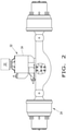
Figure 2 illustrates a top view of the rearmost shaft of the tandem shaft assembly inFigure 1 , with this assembly also including a disengagement system; -
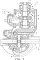
Figure 3 illustrates a cross-sectional view of the disengagement system inFigure 2 in an engaged position; and -
Figure 4 shows a cross-sectional view of the disengagement system inFigures 2 and3 in a disengaged position. - The terms "forward," "backward," "left," and "right" when used in connection with the work vehicle and/or components thereof are normally determined with reference to the forward operating travel direction of the work vehicle, but are not to be construed as limiting. The terms "longitudinal" and "transverse" are determined with reference to the forward and backward direction of the working vehicle, but they should not be interpreted as limiting.
- Now referring to the figures, more specifically to
Figure 1 , awork vehicle 10 is shown which generally includes achassis 12, acab 14 for an operator, aprime mover 16, for example adiesel engine 16, afront shaft 18, atandem shaft assembly 20 with at least twoshafts wheels 26 attached to theshafts main drive shaft 28 for transferring the driving force, i.e. a driving torque, from theengine 16 to thetandem shaft assembly 20 to provide primary traction to thework vehicle 10. Thefront wheels 26 of thefront shaft 18 are typically configured to be steered to provide directional control to thework vehicle 10. Theengine 16, via the drive train, can drive thewheels 26 of anyshaft work vehicle 10 may include more than three shafts. Thework vehicle 10 may have any desired drive configuration, such as a 6x6, 6x4, 6x2, 8x8, 8x4, 10x8 or 10x6. Thework vehicle 10 can be in the form of any desiredvehicle 10, such as a truck or a bus. - The
tandem shaft assembly 20 may be liftable, such that one of theshafts work vehicle 10 may be transformed from a 6x4 drive configuration to a 6x2 drive configuration by disengaging and/or lifting one of therear shafts tandem shaft assembly 20 may additionally include alifting element 30, for example anair bag 30, for lifting therearmost shaft 24. However, thework vehicle 10 may not include alifting element 30, and thus thetandem shaft assembly 20 may not be liftable. It is worth noting that one or both of therear shafts engine 16, regardless of whether one of therear shafts tandem shaft assembly 20 may improve fuel economy, reduce wear on therearmost shaft 24 and/or shorten the wheelbase of thework vehicle 10 to improve manoeuvrability. It is conceivable that thetandem shaft assembly 20 could be configured to lift the frontmostrear shaft 22 instead of therearmost shaft 24. - Now, referring collectively to
Figures 2 to 4 , thetandem shaft assembly 20 may additionally include adisengagement system 32 for selectively disengaging one of therear shafts engine 16. Thedisengagement system 32 is connected between the frontmostrear shaft 22 and therearmost shaft 24. Thedisengagement system 32 may generally include ahousing 34, aninput shaft 36, apinion shaft 38 and acoupling device 40 configured to disengage therearmost shaft 24 to cease transmission of the driving force from the engine 16 (Figures 3 and4 ). Thus, thecoupling device 40 can couple the input shaft andpinion shafts input shaft 36, through thepinion shaft 38, to the rearmost shaft 24 (Figure 3 ). Alternatively, thecoupling device 40 can decouple the input shaft andpinion shafts Figure 4 ). - The
input shaft 36 is configured to connect with therear shaft 22 andpinion shaft 38. Theinput shaft 36 may be in the form of aprop shaft 36 that is integrated within thedisengagement system 32, so that theprop shaft 36 connects to therear shaft differential 22. Alternatively, theinput shaft 36 may operationally couple to a booster shaft, which in turn couples to therear shaft differential 22. As shown, the front end of theinput shaft 36 hasteeth 42 that engage with theflange 44, which in turn is coupled to therear shaft differential 22. The rear end of theinput shaft 36 may include amounting element 46, such as aflange 46, which selectively engages with thecoupling device 40. Themounting element 46 may be integrally formed with theinput shaft 36, or themounting element 46 may be a separate component that is affixed to theinput shaft 36. The mountingelement 46 may have an outer diameter and/or a splined inner diameter. As shown, the rear end of theinput shaft 36 hasteeth 48 that engage with the mountingelement 46. Theinput shaft 36 is housed within thehousing 34 viabearings input shaft 36 may comprise any desired material, such as metal. - The
pinion shaft 38 is configured to connect operationally to therearmost shaft 24. Note that thepinion shaft 38 is not connected to theinput shaft 36, except that it is connected to it operationally by means of thecoupling device 40. Thepinion shaft 38 is coaxially aligned to theinput shaft 36. The front end of thepinion shaft 38 may include a mountingelement 54, such as aflange 54, which selectively couples to thecoupling device 40. The mountingelement 54 may be integrally formed with thepinion shaft 38, or the mountingelement 54 may be formed as a separate component that is affixed to thepinion shaft 38. The mountingelement 54 may have an outside diameter and/or a splined inside diameter. As shown, the front end of thepinion shaft 38 hasteeth 56 that engage the mountingelement 54. The rear end of thepinion shaft 38 may be connected to apinion gear 58, which, in turn, is configured to connect to therear shaft 24, via aring gear 60. Thepinion shaft 38 can comprise any desired material, such as metal. - The
coupling device 40 generally includes acoupler 66 and anactuator 68, which axially slides thecoupler 66 relative to the input andpinion shafts coupler 66 couples and transmits a driving force between theinput shaft 36 andpinion shaft 38 in the engaged position (Figure 3 ), or disengages theinput shaft 36 andpinion shaft 38 in the disengaged position (Figure 4 ). - The
coupler 66 may selectively engage with each mountingelement shafts coupler 66 may be in the form of anannular sleeve 66. However, thecoupler 66 may be in the form of any desired coupling element. Thecoupler 66 may have a splined inner diameter that engages with the splines of the mountingelements coupler 66 may have a receiving portion, for example a notch (unnumbered), for engaging with theactuator 68. - The
actuator 68 may include ashift fork 70, afluid device 72, and/or a tiltingelement 74. Theshift fork 70 can be slid back and forth on anactuator shaft 76 by means of a pressurized fluid from thefluid device 72 and/or by the tilting force of the tiltingelement 74, which acts on theshift fork 70 to thereby axially slide thecoupler 66. For example, in the engaged position, thefluid device 72 may not transmit force on theshift fork 70 and the tiltingelement 74 may hold or return theshift fork 70 to its initial position, which in turn slides thecoupler 66 axially forward to contact and engage both theinput shaft 36 and pinion shaft 38 (Figure 3 ). In the disengaged position, thefluid device 72 applies pressure on theshift fork 70 to overcome the tilting force of the tiltingelement 74 and slide theshift fork 70, which then slides thecoupler 66 axially backward so that thecoupler 66 only contacts and engages with thepinion shaft 38. (Figure 4 ). Thus, in the disengaged position, thecoupler 66 disengages thepinion shaft 38 so that no driving force from theengine 16 is transmitted from theinput shaft 36 to thepinion shaft 38. It is worth noting that in the disengaged position, theactuator 68 may instead slide, axially, thecoupler 66 over theinput shaft 36, instead of thepinion shaft 38, to cease transmission of the driving force to therearmost shaft 24. It is worth noting that theactuator 68 may be in the form of any desired actuator, such as a hydraulic or electric engine that is operationally connected to thecoupler 66. - The
shift fork 70 has one end that is slidably connected to theactuator shaft 76, and the other end that is fixed to thecoupler 66. Theactuator shaft 76 is parallel to theinput shaft 36. Theshift fork 70 has a front face and a rear face at its ends and its end is connected to theactuator shaft 76. As shown, the pressurized fluid acts on the front face and the tiltingelement 74 acts oppositely on the rear face, so that theshift fork 70 is moved by the fluid and the tiltingelement 74 in the opposite manner. Theshift fork 70 may be in the form of any desiredshift fork 70. - The
fluid device 72 fluidly drives theshift fork 70 such that theshift fork 70 can be slid by the pressurized fluid. Thecoupling device 40 may additionally include a sealedinternal space 78 orcavity 78 and at least onefluid inlet 80 for fluidly coupling theinternal space 78 to thefluid device 72. Thus, the fluid can remain within theinternal space 78. Theinternal space 78 is bounded by thehousing 34, a connection between theactuator shaft 76 and thehousing 34, a connection between theshift fork 70 and thehousing 34, and a connection between theshift fork 70 and theactuator shaft 76. Thefluid device 72 may be in the form of any desired fluid. As shown, the fluid is in the form of compressed air and thefluid device 72 is in the form of anair compressor 72. It is worth noting that the fluid may be in the form of any desired fluid, such as hydraulic fluid. It is conceivable that theshift fork 70 could only be moved by thefluid device 72 by applying or removing pressurized fluid on both faces of theshift fork 70. In this regard, thecoupling device 40 may include at least two fluid inlets, positioned, respectively, on each face of the shift fork 70 (not shown). - The tilting
element 74 is arranged around theactuator shaft 76 and connected between thehousing 34 and the rear face of theshift fork 70. The tiltingelement 74 is configured to apply the tilting force on the rear end face of theshift fork 70. The tiltingelement 74 may be in the form of any tilting element, such as aserpentine spring 74. - These and other advantages of the present invention will be apparent to those skilled in the art from the preceding specification. Consequently, it will be noted by those skilled in the art that modifications can be made to the embodiments described above without departing from their broad inventive concept. It should be understood that this invention is not limited to the specific disclosures described herein, but is intended to include all changes and modifications which are included in the scope and spirit of the invention.
Claims (13)
- A disengagement system (32) for a vehicle (10) with a first shaft (22) and a second shaft (24) comprising:a housing (34);an input shaft (36) configured to connect to the first shaft (22) and located within the housing (34);a pinion shaft (38) configured to connect operationally to the second shaft (24) and located within the housing (34), wherein the pinion shaft (38) is generally aligned coaxially with the input shaft (36); and(38),a coupling device (40) for selectively coupling the input shaft (36) to the pinion shaftcharacterised in that:
the coupling device (40) comprises a coupler (66) and an actuator (68) connected to the coupler (66), wherein the actuator (68) is configured to slide the coupler (66) in a direction, generally axial, with respect to the input shaft (36), so that the coupler (66) couples and transmits a driving force between the input shaft (36) and pinion shaft (38) in an engaged position of the coupling device (40), and disengages the input shaft (36) and pinion shaft (38) in a disengaged position of the coupling device (40). - The disengagement system (32) according to claim 1, characterised in that it additionally comprises an actuator shaft (76) located within the housing (34), wherein the actuator shaft (76) is parallel to the input shaft (36), and wherein the actuator (68) comprises a shift fork (70) comprising a first end slidably connected to the actuator shaft (76) and a second end fixed to the coupler (66).
- The disengagement system (32) according to claim 2, characterised in that the actuator (68) additionally comprises a fluid device (72) configured to fluidly actuate the shift fork (70) such that the shift fork (70) can slide by means of a fluid from the fluid device (72) acting on the shift fork (70).
- The disengagement system (32) according to claim 3, characterised in that the fluid remains within a sealed internal space (78), and the internal space (78) is connected by means of a connection between the actuator shaft (76) and the housing (34), a connection between the shift fork (70) and the housing (34) and a connection between the shift fork (70) and the actuator shaft (76).
- The disengagement system (32) according to claim 4, characterised in that the fluid device (72) is fluidly coupled to the internal space (78).
- The disengagement system (32), according to any one of claims 3 to 5, characterised in that the fluid device (72) is an air compressor (72), and the fluid is pressurised air, so that the shift fork (70) is pneumatically actuated.
- The disengagement system (32) according to any one of claims 3 to 6, characterised in that the actuator (68) additionally comprises a tilting element (74) arranged around the actuator shaft (76) and connected to the shift fork (70).
- The disengagement system (32) according to claim 7, characterised in that the shift fork (70) has a front face and a rear face, and the fluid acts on the front face, and the tilting element (74) acts in the opposite way on the rear face, so that the shift fork (70) can be moved by the fluid and the tilting element (74) in an opposing manner.
- The disengagement system (32) according to any one of the preceding claims, characterised in that the coupler (66) of the coupling device (40) comprises an annular sleeve (66).
- The disengagement system (32) according to claim 9, characterised in that, in the engaged position, the actuator (68) axially slides the annular sleeve (66) to contact and engage with the input shaft (36) and the pinion shaft (38), and, in the disengaged position, the actuator (68) slides the annular sleeve (66) axially to only contact the pinion shaft (38), so that the driving force is not transmitted from the input shaft (36) to the pinion shaft (38).
- The disengagement system (32) according to any one of the preceding claims, characterised in that it additionally comprises a pinion gear (58) connected to the pinion shaft (38) and configured to operationally connect operationally to the second shaft (24) of the vehicle (10).
- The disengagement system (32) according to any one of the preceding claims, characterised in that the vehicle (10) is a work vehicle (10) comprising an engine (16) providing the driving force, a front shaft (18), and a rear tandem shaft assembly (20) comprising first and second shafts (22, 24), such that the first shaft (22) is a frontmost rear shaft (22) and the second shaft (24) is a rearmost shaft (24) of the tandem shaft assembly (20).
- The disengagement system (32) according to claim 12, characterised in that the frontmost rear shaft (22) and the rearmost shaft (24) of the tandem shaft assembly (20) are selectively driven by the driving force of the engine (16), and, in the disengaging position of the coupling device (40), the actuator (68) disengages the coupler (66) to disengage the rearmost shaft (24) from the driving force of the engine (16).
Applications Claiming Priority (2)
| Application Number | Priority Date | Filing Date | Title |
|---|---|---|---|
| BR102019007822-7A BR102019007822B1 (en) | 2019-04-17 | DISCONNECTION SYSTEM FOR A VEHICLE WITH A FIRST AXLE AND A SECOND AXLE | |
| PCT/BR2020/050132 WO2020210888A1 (en) | 2019-04-17 | 2020-04-16 | Disengagement system for a vehicle with a first shaft and a second shaft |
Publications (2)
| Publication Number | Publication Date |
|---|---|
| EP3957508A1 true EP3957508A1 (en) | 2022-02-23 |
| EP3957508A4 EP3957508A4 (en) | 2023-01-18 |
Family
ID=72836736
Family Applications (1)
| Application Number | Title | Priority Date | Filing Date |
|---|---|---|---|
| EP20791925.9A Pending EP3957508A4 (en) | 2019-04-17 | 2020-04-16 | RELEASE SYSTEM FOR A VEHICLE WITH A FIRST SHAFT AND A SECOND SHAFT |
Country Status (3)
| Country | Link |
|---|---|
| EP (1) | EP3957508A4 (en) |
| CN (1) | CN113853321B (en) |
| WO (1) | WO2020210888A1 (en) |
Families Citing this family (1)
| Publication number | Priority date | Publication date | Assignee | Title |
|---|---|---|---|---|
| CN115041515B (en) * | 2022-06-02 | 2024-01-09 | 吉林建筑大学 | Automatic control device for pollution site treatment |
Family Cites Families (16)
| Publication number | Priority date | Publication date | Assignee | Title |
|---|---|---|---|---|
| GB604663A (en) * | 1944-05-04 | 1948-07-07 | Schweizerische Lokomotiv | Improvements in or relating to articulated couplings for individually driven axles of rail or other vehicles |
| US4645029A (en) * | 1985-11-05 | 1987-02-24 | Toyota Jidosha Kabushiki Kaisha | Four-wheel vehicle drive system |
| US5423235A (en) * | 1990-02-14 | 1995-06-13 | Gkn Automotive Ag | Device for switching on a drive train |
| US5370018A (en) * | 1993-03-03 | 1994-12-06 | Eaton Corporation | Internally vented interaxle differential assembly lockout shift unit |
| US20060272866A1 (en) * | 2005-06-07 | 2006-12-07 | Ziech James F | Tandem axle system |
| US7591355B2 (en) * | 2006-08-30 | 2009-09-22 | Team Industries, Inc. | Disconnect |
| BRPI0917813B8 (en) * | 2008-08-14 | 2022-07-12 | American Axle & Mfg Inc | AUTOMOTIVE VEHICLE WITH DISCONNECTABLE ALL WHEELS DRIVE SYSTEM |
| US8651994B2 (en) * | 2011-09-30 | 2014-02-18 | Arvinmeritor Technology, Llc | Drive axle assembly and disengagement system |
| EP2928718B1 (en) * | 2012-12-05 | 2020-08-19 | Mack Trucks, Inc. | Vehicle with multiple drive axle assembly with a raisable and lowerable rear drive axle, and method of neutralizing the rear drive axle and operating such a vehicle |
| WO2015080722A1 (en) * | 2013-11-27 | 2015-06-04 | Volvo Truck Corporation | Vehicle with rear drive axle assembly and the ability to neutralize |
| WO2016205480A1 (en) * | 2015-06-16 | 2016-12-22 | Dana Heavy Vehicle Systems Group, Llc | Disconnectable 6x4 tandem axle and method of operation |
| BR102015018592A2 (en) * | 2015-08-03 | 2017-02-07 | Cnh Ind Latin America Ltda | axle and vehicle coupling |
| SE540826C2 (en) * | 2016-04-29 | 2018-11-20 | Scania Cv Ab | An axle gear system, a driving axle system and a motor vehicle |
| CN113815393A (en) * | 2016-05-06 | 2021-12-21 | 艾里逊变速箱公司 | Axle assembly with electric motor |
| EP3554878B1 (en) * | 2016-12-14 | 2023-01-04 | IVECO S.p.A. | A power transmission assembly for tandem axles |
| US10591037B2 (en) * | 2018-08-09 | 2020-03-17 | Arvinmeritor Technology, Llc | Drive axle system having a planetary interaxle differential unit |
-
2020
- 2020-04-16 CN CN202080037804.2A patent/CN113853321B/en active Active
- 2020-04-16 EP EP20791925.9A patent/EP3957508A4/en active Pending
- 2020-04-16 WO PCT/BR2020/050132 patent/WO2020210888A1/en not_active Ceased
Also Published As
| Publication number | Publication date |
|---|---|
| WO2020210888A1 (en) | 2020-10-22 |
| CN113853321B (en) | 2024-01-05 |
| EP3957508A4 (en) | 2023-01-18 |
| BR102019007822A2 (en) | 2020-10-27 |
| CN113853321A (en) | 2021-12-28 |
Similar Documents
| Publication | Publication Date | Title |
|---|---|---|
| US10988193B2 (en) | Disconnectable work implement drive system | |
| JP6309956B2 (en) | Vehicle equipped with hydraulic assist by torque transmission from drive shaft to drive shaft | |
| EP2750911A1 (en) | A forward carrier assembly with a reversible inter-axle differential for a tadem axle vehicle, a powertrain for a tandem axle vehicle, and a tandem axle vehicle | |
| CN100475593C (en) | All-wheel drive torque vector control system | |
| EP2953809B1 (en) | Hydrostatic and direct drive transmission | |
| US11479116B2 (en) | Auxiliary power take-off assembly | |
| EP3957508A1 (en) | Disengagement system for a vehicle with a first shaft and a second shaft | |
| CN100558576C (en) | Drive system for vehicle powertrain and vehicle comprising same | |
| SE540826C2 (en) | An axle gear system, a driving axle system and a motor vehicle | |
| CN114096431B (en) | Drive axle for a vehicle having a first axle and a second axle as a lift axle | |
| BR102019007822B1 (en) | DISCONNECTION SYSTEM FOR A VEHICLE WITH A FIRST AXLE AND A SECOND AXLE | |
| RU2808306C2 (en) | Drive shaft for vehicle with first axle and second axle which can be lifted | |
| US11091030B2 (en) | Disconnect mechanism for a tandem axle system | |
| US20090138166A1 (en) | Multiplexed Hydraulic Control for a Two-Coupling All-Wheel Drive System | |
| EP4046818B1 (en) | Wheel hub for mounting a wheel on an axle of a work vehicle | |
| KR102582845B1 (en) | Work vehicle and driving extraction device of work vehicle | |
| CN223515338U (en) | Middle and small hydraulic drive four-wheel drive axle assembly for grain harvester | |
| EP0248005B1 (en) | Power transmission coupling | |
| KR102583451B1 (en) | Pto hydraulic control valve device | |
| US20250065714A1 (en) | Transmission | |
| US8220350B2 (en) | Gearbox for lift truck with telescopic jib, and machine equipped with same | |
| EP0945397B1 (en) | A vehicle with a lifting boom, having a power takeoff driven by a mechanical transmission | |
| JPS6319448A (en) | Normally claw gear transmission | |
| CN120251625A (en) | A transmission shaft with an electric clutch | |
| CN121336607A (en) | Harvester chassis and harvester |
Legal Events
| Date | Code | Title | Description |
|---|---|---|---|
| STAA | Information on the status of an ep patent application or granted ep patent |
Free format text: STATUS: THE INTERNATIONAL PUBLICATION HAS BEEN MADE |
|
| PUAI | Public reference made under article 153(3) epc to a published international application that has entered the european phase |
Free format text: ORIGINAL CODE: 0009012 |
|
| STAA | Information on the status of an ep patent application or granted ep patent |
Free format text: STATUS: REQUEST FOR EXAMINATION WAS MADE |
|
| 17P | Request for examination filed |
Effective date: 20211022 |
|
| AK | Designated contracting states |
Kind code of ref document: A1 Designated state(s): AL AT BE BG CH CY CZ DE DK EE ES FI FR GB GR HR HU IE IS IT LI LT LU LV MC MK MT NL NO PL PT RO RS SE SI SK SM TR |
|
| DAV | Request for validation of the european patent (deleted) | ||
| DAX | Request for extension of the european patent (deleted) | ||
| RIN1 | Information on inventor provided before grant (corrected) |
Inventor name: NICORA, FABIO Inventor name: PEREIRA DE LEMOS, JOSE FRANCIVALDO |
|
| A4 | Supplementary search report drawn up and despatched |
Effective date: 20221216 |
|
| RIC1 | Information provided on ipc code assigned before grant |
Ipc: B60K 17/36 20060101ALI20221212BHEP Ipc: B60K 17/344 20060101ALI20221212BHEP Ipc: B62D 61/12 20060101ALI20221212BHEP Ipc: F16H 29/18 20060101ALI20221212BHEP Ipc: F16H 29/12 20060101ALI20221212BHEP Ipc: B60B 35/12 20060101ALI20221212BHEP Ipc: B60K 23/08 20060101ALI20221212BHEP Ipc: B60K 17/34 20060101AFI20221212BHEP |
|
| STAA | Information on the status of an ep patent application or granted ep patent |
Free format text: STATUS: EXAMINATION IS IN PROGRESS |
|
| 17Q | First examination report despatched |
Effective date: 20250613 |