EP3957129B1 - Stromausfallerkennung und -meldung - Google Patents
Stromausfallerkennung und -meldung Download PDFInfo
- Publication number
- EP3957129B1 EP3957129B1 EP20746397.7A EP20746397A EP3957129B1 EP 3957129 B1 EP3957129 B1 EP 3957129B1 EP 20746397 A EP20746397 A EP 20746397A EP 3957129 B1 EP3957129 B1 EP 3957129B1
- Authority
- EP
- European Patent Office
- Prior art keywords
- node
- time
- outage
- packet
- mesh network
- Prior art date
- Legal status (The legal status is an assumption and is not a legal conclusion. Google has not performed a legal analysis and makes no representation as to the accuracy of the status listed.)
- Active
Links
Images


Classifications
-
- H—ELECTRICITY
- H04—ELECTRIC COMMUNICATION TECHNIQUE
- H04L—TRANSMISSION OF DIGITAL INFORMATION, e.g. TELEGRAPHIC COMMUNICATION
- H04L43/00—Arrangements for monitoring or testing data switching networks
- H04L43/10—Active monitoring, e.g. heartbeat, ping or trace-route
- H04L43/106—Active monitoring, e.g. heartbeat, ping or trace-route using time related information in packets, e.g. by adding timestamps
-
- G—PHYSICS
- G01—MEASURING; TESTING
- G01R—MEASURING ELECTRIC VARIABLES; MEASURING MAGNETIC VARIABLES
- G01R22/00—Arrangements for measuring time integral of electric power or current, e.g. electricity meters
- G01R22/06—Arrangements for measuring time integral of electric power or current, e.g. electricity meters by electronic methods
- G01R22/061—Details of electronic electricity meters
- G01R22/068—Arrangements for indicating or signaling faults
-
- H—ELECTRICITY
- H04—ELECTRIC COMMUNICATION TECHNIQUE
- H04W—WIRELESS COMMUNICATION NETWORKS
- H04W84/00—Network topologies
- H04W84/18—Self-organising networks, e.g. ad-hoc networks or sensor networks
-
- G—PHYSICS
- G01—MEASURING; TESTING
- G01R—MEASURING ELECTRIC VARIABLES; MEASURING MAGNETIC VARIABLES
- G01R31/00—Arrangements for testing electric properties; Arrangements for locating electric faults; Arrangements for electrical testing characterised by what is being tested not provided for elsewhere
- G01R31/08—Locating faults in cables, transmission lines, or networks
-
- H—ELECTRICITY
- H02—GENERATION; CONVERSION OR DISTRIBUTION OF ELECTRIC POWER
- H02H—EMERGENCY PROTECTIVE CIRCUIT ARRANGEMENTS
- H02H1/00—Details of emergency protective circuit arrangements
- H02H1/0007—Details of emergency protective circuit arrangements concerning the detecting means
-
- H—ELECTRICITY
- H02—GENERATION; CONVERSION OR DISTRIBUTION OF ELECTRIC POWER
- H02H—EMERGENCY PROTECTIVE CIRCUIT ARRANGEMENTS
- H02H3/00—Emergency protective circuit arrangements for automatic disconnection directly responsive to an undesired change from normal electric working condition with or without subsequent reconnection ; integrated protection
- H02H3/02—Details
- H02H3/04—Details with warning or supervision in addition to disconnection, e.g. for indicating that protective apparatus has functioned
-
- H—ELECTRICITY
- H04—ELECTRIC COMMUNICATION TECHNIQUE
- H04L—TRANSMISSION OF DIGITAL INFORMATION, e.g. TELEGRAPHIC COMMUNICATION
- H04L41/00—Arrangements for maintenance, administration or management of data switching networks, e.g. of packet switching networks
- H04L41/06—Management of faults, events, alarms or notifications
- H04L41/0604—Management of faults, events, alarms or notifications using filtering, e.g. reduction of information by using priority, element types, position or time
- H04L41/0622—Management of faults, events, alarms or notifications using filtering, e.g. reduction of information by using priority, element types, position or time based on time
-
- H—ELECTRICITY
- H04—ELECTRIC COMMUNICATION TECHNIQUE
- H04L—TRANSMISSION OF DIGITAL INFORMATION, e.g. TELEGRAPHIC COMMUNICATION
- H04L41/00—Arrangements for maintenance, administration or management of data switching networks, e.g. of packet switching networks
- H04L41/06—Management of faults, events, alarms or notifications
- H04L41/0686—Additional information in the notification, e.g. enhancement of specific meta-data
-
- H—ELECTRICITY
- H04—ELECTRIC COMMUNICATION TECHNIQUE
- H04L—TRANSMISSION OF DIGITAL INFORMATION, e.g. TELEGRAPHIC COMMUNICATION
- H04L69/00—Network arrangements, protocols or services independent of the application payload and not provided for in the other groups of this subclass
- H04L69/30—Definitions, standards or architectural aspects of layered protocol stacks
- H04L69/32—Architecture of open systems interconnection [OSI] 7-layer type protocol stacks, e.g. the interfaces between the data link level and the physical level
- H04L69/322—Intralayer communication protocols among peer entities or protocol data unit [PDU] definitions
- H04L69/324—Intralayer communication protocols among peer entities or protocol data unit [PDU] definitions in the data link layer [OSI layer 2], e.g. HDLC
-
- H—ELECTRICITY
- H04—ELECTRIC COMMUNICATION TECHNIQUE
- H04W—WIRELESS COMMUNICATION NETWORKS
- H04W24/00—Supervisory, monitoring or testing arrangements
- H04W24/04—Arrangements for maintaining operational condition
-
- H—ELECTRICITY
- H04—ELECTRIC COMMUNICATION TECHNIQUE
- H04W—WIRELESS COMMUNICATION NETWORKS
- H04W24/00—Supervisory, monitoring or testing arrangements
- H04W24/08—Testing, supervising or monitoring using real traffic
-
- H—ELECTRICITY
- H04—ELECTRIC COMMUNICATION TECHNIQUE
- H04B—TRANSMISSION
- H04B1/00—Details of transmission systems, not covered by a single one of groups H04B3/00 - H04B13/00; Details of transmission systems not characterised by the medium used for transmission
- H04B1/69—Spread spectrum techniques
- H04B2001/6908—Spread spectrum techniques using time hopping
-
- H—ELECTRICITY
- H04—ELECTRIC COMMUNICATION TECHNIQUE
- H04L—TRANSMISSION OF DIGITAL INFORMATION, e.g. TELEGRAPHIC COMMUNICATION
- H04L41/00—Arrangements for maintenance, administration or management of data switching networks, e.g. of packet switching networks
- H04L41/06—Management of faults, events, alarms or notifications
- H04L41/0654—Management of faults, events, alarms or notifications using network fault recovery
-
- H—ELECTRICITY
- H04—ELECTRIC COMMUNICATION TECHNIQUE
- H04L—TRANSMISSION OF DIGITAL INFORMATION, e.g. TELEGRAPHIC COMMUNICATION
- H04L45/00—Routing or path finding of packets in data switching networks
- H04L45/02—Topology update or discovery
- H04L45/026—Details of "hello" or keep-alive messages
-
- H—ELECTRICITY
- H04—ELECTRIC COMMUNICATION TECHNIQUE
- H04W—WIRELESS COMMUNICATION NETWORKS
- H04W40/00—Communication routing or communication path finding
- H04W40/24—Connectivity information management, e.g. connectivity discovery or connectivity update
-
- Y—GENERAL TAGGING OF NEW TECHNOLOGICAL DEVELOPMENTS; GENERAL TAGGING OF CROSS-SECTIONAL TECHNOLOGIES SPANNING OVER SEVERAL SECTIONS OF THE IPC; TECHNICAL SUBJECTS COVERED BY FORMER USPC CROSS-REFERENCE ART COLLECTIONS [XRACs] AND DIGESTS
- Y02—TECHNOLOGIES OR APPLICATIONS FOR MITIGATION OR ADAPTATION AGAINST CLIMATE CHANGE
- Y02D—CLIMATE CHANGE MITIGATION TECHNOLOGIES IN INFORMATION AND COMMUNICATION TECHNOLOGIES [ICT], I.E. INFORMATION AND COMMUNICATION TECHNOLOGIES AIMING AT THE REDUCTION OF THEIR OWN ENERGY USE
- Y02D30/00—Reducing energy consumption in communication networks
- Y02D30/70—Reducing energy consumption in communication networks in wireless communication networks
Definitions
- the invention relates to methods for detecting and reporting a power outage of a node, and further to systems and a node of a mesh network.
- This disclosure relates generally to processes for detecting and reporting node outages (e.g., premise power outage or grid power outage) within a wireless network.
- Networked systems such as networks of smart power, gas, and water meters and other smart devices (i.e., devices capable of connecting to and communicating with other devices or networks), are capable of interconnecting with each other for inter-device communication. Further, one or more of the smart devices within the networked systems may be capable of interconnecting with the internet or other networks.
- a networked system provides the smart devices with a mechanism to communicatively couple with one another and exchange data.
- the networked system may include one or more nodes that connect to a network (e.g., the internet or an intranet) either directly or indirectly through additional layers of parent and root nodes or collectors.
- the networked system may also include nodes that link with the parent nodes or other child nodes to exchange data across the networked system.
- US2014/085105A1 (Vaswani - Published 27 March 2014 ) relates to identifying and targeting power outages., and discloses that when an electric meter experiences a loss in power, it can then transmit an immediate notification regarding the loss in power to the selected communication node.
- US2017/134395A1 (Enns - Published 11 May 2017 ) relates to secure aggregated event reporting, and discloses a method including: determining, by a device, that a status change has occurred at the device; and transmitting, by the device, a status change report to one or more parent devices toward a head end system.
- US2012/192025A1 (Veillette - Published 26 July 2012 ) relates to reporting of status changes, such as but not limited to power outages and/or power restorations, throughout a smart grid system.
- US2013/166641A1 (Kan - Published 27 June 2013 ) relates to a power outage detection system, and discloses a system including a device configured to increment a reboot counter when the device is powered up, and to transmit a first message when the device loses power and a second message when the device is powered up, and a back office system. A finite state machine then outputs an accurate indication of the state of the device.
- a dying node may have some remaining energy to generate and transmit a network message to a headend system to report its power outage.
- the network node configured to route the network messages of the dying node to the headend system may also suffer a power outage and cannot function properly.
- the network message reporting the power outage of the dying node may never be received by other nodes in the networked system and reported to a headend system.
- outage events of nodes in the networked system may not be adequately or consistently detected and reported to the headend system for further remediating action.
- a method for detecting and reporting a power outage of a node include a first node in a mesh network detecting that a power outage has occurred at the first node, determining that a predetermined period of time has passed since detecting the power outage and that power is not restored. The method further includes, in response to determining that the predetermined period of time has passed and that the power is not restored, broadcasting, by the first node after waiting for a random offset period of time, a last gasp packet on the mesh network.
- the last gasp packet is generated using a first packet format containing a smaller number of data units than a regular packet format used by the mesh network for communication.
- the method also includes receiving, by a second node in the mesh network, the last gasp packet.
- the second node is a neighboring node of the first node that is communicatively connected to the second node through the mesh network.
- the method further includes determining, by the second node, estimated time of the power outage based on time of receiving the last gasp packet and the predetermined period of time; generating, by the second node, an outage alarm message in the regular packet format used by the mesh network for communication based on the received last gasp packet and the estimated time of the power outage; and transmitting, by the second node, the outage alarm message to a headend system of the mesh network.
- a system in another example, includes a first node of a mesh network, the first node configured for detecting that a power outage has occurred at the first node, determining that a predetermined period of time has passed since detecting the power outage and that the power is not restored, and in response to determining that the predetermined period of time has passed and that the power is not restored, broadcasting, after waiting for a random offset period of time, a last gasp packet on the mesh network.
- the last gasp packet is generated using a first packet format containing a smaller number of data units than a regular packet format used by the mesh network for communication.
- the system further includes a plurality of neighboring nodes of the first node that are communicatively connected to the first node through the mesh network.
- Each of the plurality of neighboring nodes is configured for receiving the last gasp packet from the first node, determining estimated time of the power outage based on time of receiving the last gasp packet and the predetermined period of time, generating an outage alarm message in the regular packet format used by the mesh network for communication based on the received last gasp packet and the estimated time of the power outage, and transmitting the outage alarm message to a headend system of the mesh network.
- a node of a network includes a processor configured to execute computer-readable instructions, and a memory configured to store the computer-readable instructions that, when executed by the processor, cause the processor to perform operations.
- the operations include receiving a last gasp packet from a dying node indicating a power outage at the dying node.
- the node is a neighboring node of the dying node that is communicatively connected to the node through the network.
- the last gasp packet is generated by the dying node after a predetermined period of time has passed since detecting the power outage and is broadcast on the network using a first packet format containing a smaller number of data units than a regular packet format used by the network for communication.
- the operations further include determining an estimated time of the power outage based on time of receiving the last gasp packet and the predetermined period of time, generating an outage alarm message in the regular packet format used by the network for communication based on the received last gasp packet and the estimated time of the power outage, and transmitting the outage alarm message to a headend system of the network.
- a node outage can include the premises power outage at the location of the node (e.g., the power outage only occurs at the premises level at the location of the node and affects a single node) or the grid power outage at the location of the node (e.g., the power outage occurs at the power grid level and can impact multiple premises and multiple nodes).
- a node may be any point in the networked system capable of transmitting data to and receiving data from other nodes or a centralized network (e.g., the internet or an intranet).
- the networked system includes a process that leverages node capabilities to manage node outage detection at the nodes connected to the networked system.
- a node detects that it is experiencing a power outage.
- the node that suffers the power outage is also referred to herein as a "dying node” or a “non-functioning node.”
- the dying node Upon detecting the power outage, the dying node operates for a short period of time before completely shutting down, such as by using energy stored in internal capacitors of the node. During this short period of time, the dying node can initiate an ordered shutdown process such as turning off various components of the dying node, saving relevant data to the storage device, and the like.
- the dying node also generates a last gasp packet reporting its power outage.
- the last gasp packet is generated in a format that contains less data than a regular message used by the networked system for communication.
- the last gasp packet includes only necessary information such as an indication of the packet as a last gasp packet and an identifier of the node. Other information that would otherwise be included in a regular outage alarm message, such as the time of the power outage, the destination information of the packet, is omitted from the last gasp packet.
- the dying node waits for a sustained period before sending out the last gasp packet. Further, a random offset time period is added to the waiting time to reduce the likelihood of the collision in transmitting the last gasp packet.
- the dying node is configured to broadcast the last gasp packet through the network. Any neighboring node that can directly communicate with the dying node (including, but not limited to, the node configured for routing messages for the dying node) can receive the last gasp packet. In this way, the last gasp packet may be received by multiple neighboring nodes of the dying node thereby increasing the chances of the last gasp packet reaching a functioning node.
- Each of the functioning neighboring nodes of the dying node that received the last gasp packet converts the last gasp packet into an outage alarm message by following the regular format of the network message and transmits it to the headend system.
- each neighboring node waits for a randomization period of time before transmitting the outage alarm message.
- each neighboring node listens for outage alarm messages transmitted by other nodes. If an outage alarm message reporting the outage at the dying node has been transmitted by another node during the randomization period of time, the neighboring node will refrain from transmitting the outage alarm message.
- the neighboring node will transmit the outage alarm message to a headend system through normal packet routing.
- the headend system can cause measures to be taken to address the non-functioning node. For example, technicians may be deployed to perform physical inspections and repairs on the non-functioning node.
- the information about the non-functioning nodes may also be used to provide accurate outage information to customers or to identify the scope of the problem.
- this node When the power at the non-functioning node is recovered, this node has sufficient power and it can generate a power recovery message in the regular network message format and send the power recovery message to the headend system through normal packet routing to report its power recovery.
- Techniques described in the present disclosure increase the reliability of the node power outage detection and reporting. For instance, by reducing the size of the last gasp packet, the energy consumption at the dying node for generating and transmitting the last gasp packet can be reduced thereby increasing the chance of the last gasp packet being successfully transmitted out using the limited energy of the dying node.
- broadcasting the last gasp packet instead of unicasting can increase the likelihood of the last gasp packet reaching a functioning node so that the power outage can be reliably reported to the headend system.
- Various other mechanisms such as the random offset period added by the dying node before transmitting the last gasp packet, the randomization period of time during which a neighboring node listening for the outage alarm message reported by other nodes, can further reduce network transmission collision and increase the reliability of reporting the power outage of a node.
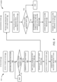
- FIG. 1 is a block diagram illustrating an example of a networked system 100 and a mesh network 102.
- the networked system 100 and the mesh network 102 provides a network infrastructure for smart devices (e.g., resource consumption meters, vehicles, home appliances, etc. that include communication technology) to communicate across a network of nodes (i.e., other smart devices), the internet, and/or an intranet.
- smart devices e.g., resource consumption meters, vehicles, home appliances, etc. that include communication technology
- nodes i.e., other smart devices
- the networked system 100 includes a headend system 104, which may function as a central processing system that receives a stream of data from a network 120.
- the network 120 may be the internet, an intranet, or any other data communication network.
- the mesh network 102 includes various nodes 112A-112H (which may be referred to herein individually as a node 112 or collectively as the nodes 112). These nodes 112 include nodes such as measuring nodes for collecting data from the respective deployed location of the nodes, processing nodes for processing data available to the nodes, router nodes for forwarding data received from one node to another node in the mesh network 102, or nodes that are configured to perform a combination of these functions.
- the mesh network 102 is associated with a power distribution network to deliver measurement data or other data obtained in the power distribution network.
- nodes 112 include electricity meters implemented to measure various operating characteristics of the power distribution network and to transmit the collected data through the mesh network 102 to root nodes 114A and 114B (which may be referred to herein individually as a root node 114 or collectively as the root nodes 114).
- Root nodes 114 of the mesh network 102 may be configured for communicating with the nodes 112 to perform operations such as managing the nodes 112, collecting data from the nodes 112, and forwarding data to a headend system 104.
- a root node 114 can also be configured to function as a node to measure and process data itself.
- the root nodes 114 may be personal area network (PAN) coordinators, gateways, or any other devices capable of communicating with the headend system 104.
- PAN personal area network
- the root nodes 114 ultimately transmit the generated and collected data to the headend system 104 via the network 120.
- the root nodes 114 may also receive from the headend system 104 network management messages and transmit the network management messages to the nodes 112.
- the root node 114 itself or the nodes 112 may also issue and transmit network management messages to other nodes 112.
- the data and network management transmitted between nodes 114 and 112 may be collectively referred to herein as "communication messages.” These communication messages are transmitted and routed through data links 110 between nodes 114 and 112.
- the communication messages are generated in a regular format so that nodes 114 and 112 on the mesh network 102 can understand the communication messages and route them to the correct destination nodes or the headend system 104.
- Communication messages are typically routed between a node and the headend system 104 or among the nodes according to a node hierarchy of the mesh network 102.
- the root node 114A which communicates directly with the headend system 104 through the network 120, may generally be referred to as a parent node due to data links with the nodes 112A and 112B that are located at a node layer (e.g., layer one) below the root node 114A.
- nodes 112A and 112B may also be referred to as parent nodes due to data links with nodes 112C, 112D, and 112E that are located at a node layer (e.g., layer two) below the nodes 112A and 112B.
- nodes 114B and 112G may also be referred to as parent nodes due to the data link with nodes 112F-112G and node 112H, respectively, that are located at a node layer below the respective nodes.
- the nodes 112 may all funnel information up through the node layers to the root node 114 and ultimately to the headend system104.
- Links 110 may be created by storing neighboring node information in neighbor caches of the nodes 112 and 114 that provide indications to the nodes of the other nodes through which data may be routed.
- the neighbor cache of the node 112D may include neighboring node information identifying that data collected at the node 112D should be transmitted to the node 112B.
- the neighbor cache of the node 112B may include neighboring node information identifying that the node 112B should transmit relevant information to the node 112D (e.g., network management messages or other information from the headend system 104) and also identifying that the node 112B should transmit data collected by the node 112B and data received from the node 112D to the root node 114A.
- Such a data transmission scheme may continue up through the node layers of the mesh network 102 if there are more node layers.
- fewer or more nodes 112 may be included in the mesh network 102, and more root nodes 114 may also be included in the networked system 100.
- the mesh network 102 depicted in FIG. 1 includes a root node layer (i.e., the root node 114), layer one (i.e., the nodes 112A, 112B, 112F, and 112G), and layer two (i.e., the nodes 112C, 112D, 112E, and 112H), fewer or more node layers are also contemplated.
- FIG. 1 depicts a specific network topology (e.g., a DODAG tree topology), other network topologies are also possible (e.g., a ring topology, a mesh topology, a star topology, etc.).
- the headend system 102 may keep track of the operational status of the nodes 114 and 112. To do so, each of the nodes 114 and 112 can be configured to report its status to the headend system 104. For example, if a node 114 or 112 experiences a power outage, this node can report the power outage to the headend system 104. If the power is recovered later at the node, the node can report the power recovery to the headend system 104. In the example shown in FIG. 1 , the node 112D is experiencing a power outage (as such node 112D is also referred to as the dying node 112D).
- the dying node 112D Upon detecting the power outage, the dying node 112D generates a last gasp packet 118 to indicate the power outage.
- the dying node 112D broadcasts the last gasp packet 118 instead of sending it directly to node 112B according to the normal transmission procedure as discussed above. In this way, the last gasp packet 118 can reach multiple neighboring nodes of the dying node 112D that can directly communicate with the dying node 112D, such as nodes 112B, 112C, 112E, and 112H.
- the last gasp packet 118 is generated in a format containing less data than the regular format used to transmit the communication messages.
- each of the neighboring nodes that have not lost power and function normally reformat the packet into an outage alarm message 108.
- the outage alarm message 108 is generated by following the regular format of communication messages on the network 102 so that the outage alarm message 108 can be properly routed to the headend system 104.
- the neighboring node transmits the outage alarm message 108 to the headend system 104 to report the power outage at the dying node 112D.
- the neighboring node 112C generates an outage alarm message 108 based on the last gasp packet 118 and sends it to the headend system 104 through nodes 112A and 114A.
- the outage alarm message 108 generated by the neighboring node is the same as an outage alarm message that otherwise would have been generated by the dying node. So the generation of the outage alarm message 108 is transparent to the rest of the system. Generating an outage alarm message 108 the same as an outage alarm message that otherwise would have been generated by the dying node based on the last gasp packet 118 sent by the dying node is referred to herein as a "proxy" function of the neighboring node. When performing the proxy function, the neighboring node is referred to as a proxy of the dying node.
- the outage alarm message 108 for the dying node 112D may be combined or consolidated with the outage alarm messages for other dying nodes in an alarm packet.
- the alarm packet can include an indication of multiple nodes that are in a power outage. Certain mechanisms can be implemented at each neighboring node to reduce the likelihood of more than one neighboring node sending the outage alarm message 108. Additional details of generating and sending the last gasp packet 118 and outage alarm message 108 are described with regard to FIGS. 2-4 .
- a filtering and consolidation process may occur to prevent transmission of unnecessary or repeat outage indications.
- the node 112 or 114 that receives the alarm packet may parse the alarm packet or outage alarm message into node identifiers that indicate which of the nodes 112 or 114 are in the alarm packet as being in an outage.
- the node can analyze the node identifiers for repeat alarm indications.
- the node receiving the alarm packet or the outage alarm message already knows that an alarm packet or an outage alarm message has already been sent, the node can remove the node identifier from the alarm packet or outage alarm message and forward the updated alarm packet or outage alarm message to the next topologically higher node layer of the mesh network 102.
- the root node 114 may also perform the filtering and consolidation process and transmit the resulting alarm packet to the headend system 104 by way of the network 120.
- the headend system 104 may deploy technicians to address the one or more nodes indicated by the alarm packet as being in outage including the node 112D. For example, the technician may be deployed to repair or replace the nodes identified by the alarm packet or to address a cause of the outage. Further, the headend system 104 may maintain a record of the nodes that are in an outage.
- the node 112D can generate a power recovery message using the regular format for communication messages and send the power recovery message to the headend system through node 112B and node 114A according to its normal routing path to report its power recovery.
- FIG. 2 is a diagram illustrating an example of a timeline for detecting and reporting the power outage of a node in a networked system, according to certain aspects of the disclosure.
- FIG. 2 illustrates two synchronized time axes: the lower time axis is for a dying node 202 and the upper one is for a neighboring node 204 of the dying node 202.
- the dying node 202 detects the power outage, and between time T1 and T2, the dying node 202 performs an orderly shutdown process.
- the orderly shutdown process can include orderly turning off components such as the receiver, and stopping communication functions, such as protocol activities, packet processing, and so on. Stopping these communications components and functions can help reduce energy usages. Additionally, other non-critical processor activities can also be shutdown including high-speed clocks. Only a low consumption timer used for counting the sustained period can be maintained powered, before sending the last gasp packet.
- context information can be stored in a nonvolatile storage device.
- the dying node 202 also generates a last gasp packet 118 for reporting its power outage.
- the last gasp packet 118 is generated in a simplified format that contains fewer data units than the regular packet format used to generate the communication messages transmitted on the network.
- FIG. 3 shows an example of the last gasp packet 118 and an outage alarm message 108 if the power outage is reported by following the regular packet format.
- the last gasp packet 118 contains a last gasp information field containing necessary information used for reporting the outage, such as the identifier (ID) of the dying node 202.
- the last gasp packet 118 in this example also includes header fields such as physical layer (PHY) header and Media Access Control (MAC) layer header indicating that this packet is a last gasp packet 118 so that a receiving node knows to parse the packet according to the format of the last gasp packet 118.
- FIG. 3 also shows the example size of each field of the last gasp packet 118. In this example, the total size of a last gasp packet 118 is 25 bytes.
- the outage alarm message 108 that follows the regular packet format of the network may require more information and thus have a larger packet size.
- the outage alarm message 108 can contain an outage information field describing the outage, such as the ID of the dying node, the timestamp indicating the time when the power outage occurred, and so on.
- the outage alarm message 108 may also need proper headers for different network layers, such as the PHY header, MAC header, IP header, UDP header, application header, and the like. Other fields may also be included in the outage alarm message 108. In the example shown in FIG.
- the size of an outage alarm message 108 is 47 bytes, which is almost twice the size of the last gasp packet 118.
- the last gasp packet 118 has a simple packet structure and a smaller size. As a result, a dying node 202 needs much less energy to generate and transmit a last gasp packet 118 than an outage alarm message 108.
- the dying node 202 waits for a sustained period 206 (the time period from time T2 to T3), this helps to avoid reporting a momentary power outage.
- the sustained period of time may be set to several seconds to a minute.
- the sustained period of time can be predetermined by an entity associated with the headend system, such as a utility company.
- the dying node 202 determines that the power outage is not momentary and it sends the last gasp packet 118.
- the power outage may impact a large area causing multiple nodes 114 and 112 to lose power.
- a dying node 202 sends the last gasp packet 118 right after the expiration of the sustained period 206, collisions may occur between multiple dying nodes.
- the dying node 202 is configured to add a random offset period 210 (i.e., the time period between T3 and T4) before transmitting the last gasp packet 118.
- the dying node 202 waits for another time period (i.e., the random offset 210) before sending out the last gasp packet 118.
- the random offset 210 can be randomly generated by the dying node 202 within a last gasp randomization range.
- the last gasp randomization range can be 1 to 5 seconds.
- the dying node 202 can randomly select a value within this range to use as the random offset period 210. The selection can follow a uniform distribution over the last gasp randomization range or other types of distributions.
- the dying node 202 sends the last gasp packet 118 through broadcasting.
- the broadcast last gasp packet 118 may reach each of the neighboring nodes of the dying node 202 that are within the communication range of the dying node 202 and are still functioning, such as the neighboring node 204.
- the time when the neighboring node 204 revives the last gasp packet 118 is denoted as time T5 in FIG. 2 . Since the neighboring node 204 is functioning and has sufficient power, the neighboring node 204 converts the last gasp packet 118 into an outage alarm message 108 that follows the regular format for communication messages transmitted through the network, such as the outage alarm message 108 shown in FIG. 3 .
- the neighboring node 204 transmits the outage alarm message 108 to the headend system 104 through the node layers of the network as discussed above with regard to FIG. 1 .
- a neighboring node that is also experiencing a power outage may also receive the last gasp packet 118 sent by the dying node 202 (e.g., if the receiver is not turned off during the orderly shutdown procedure).
- the dying neighboring node can ignore the received last gasp packet 118 and perform a process to handle its own power outage detection and reporting in a way similar to that of the dying node described herein.
- the neighboring node 204 is configured to wait for a randomization period of time 212 before sending out the outage alarm message 108.
- the randomization period of time 212 is randomly selected by the neighboring node 204 within an outage alarm randomization range.
- the outage alarm randomization range can be from 0 to 15 seconds.
- the neighboring node 204 can randomly select a value within this range to use as the randomization period 212. The selection can follow a uniform distribution over the last gasp randomization range or other types of distributions. When selecting the randomization period of time 212, different neighboring nodes 204 may follow the same or different distributions.
- the neighboring node 204 listens on the network for outage alarm messages 108 reporting the power outage of the same dying node 202. If the neighboring node 204 detects that an outage alarm message 108 has been sent by another node to report the power outage of the dying node 202, the neighboring node 204 will refrain from sending the outage alarm message 108 to the headend system 104 to avoid duplicate power outage reporting. If the neighboring node 204 did not detect other outage alarm message 108 on the network during the randomization period of time 212, the neighboring node 204 transmits the generated outage alarm message 108 at the end of the randomization period of time 212, denoted as T6 in FIG. 2 .
- the node in the network cannot detect and parse communication messages.
- the neighboring node 204 may not be able to determine whether an outage alarm message 108 has been sent by another node or not.
- the neighboring node 204 will send the outage alarm message 108 after the randomization period of time 212 has passed. Removing duplicate outage alarm messages 108 can be performed by nodes at higher layers in the network as discussed above with regard to FIG. 1 .
- the dying node 202 instead of the dying node 202 generating and sending the outage alarm message 108 to the headend system 104, the dying node 202 relies on its neighboring nodes which have more energy to generate and send the outage alarm message 108 on its behalf.
- the dying node 202 can use its limited energy to focus on generating and transmitting the smaller and simpler last gasp packet 118 without complying with the regular packet format of the network. This increases the chances of the successful generation and transmission of the dying node 202 before the dying node 202 completely shuts down.
- the dying node 202 can generate a power recovery message in the regular format of communication message and send the power recovery message to the headend system 104 itself without using its neighboring nodes as a proxy.
- the dying node 202 waits for the sustained period 206 before sending the last gasp packet 118 in order to rule out the scenarios of momentary power loss. In some cases, however, the remaining energy of the dying node 202 after power loss may not last long enough to allow it to wait for the sustained period 206 in addition to the random offset 210. As such, in some implementations, the dying node 202 is configured to skip the sustained period 206. In other words, after detecting the power outage and performing the ordered shutdown procedure, the dying node 202 only waits for the random offset time period before broadcasting the dying node 202.
- the neighboring nodes are configured to wait for a sustained period of time, which can be the same or different from the sustained period 206, before proceeding to the next step of generating the outage alarm message 108 and listening on the network for other outage alarm messages 108 during the randomization period of time 212.
- the sustained period used at the neighboring node 204 may vary from several tens of seconds to several minutes. If the neighboring node 204 does not receive further packets from the dying node 202 during the sustained period, the neighboring node 204 can determine that the power outage is not momentary and will proceed to the next step of the power outage reporting described above (e.g., generating the outage alarm message 108 and waiting for the randomization period of time 212). If the neighboring node 204 receives further packets from the dying node 202 during the sustained period, the neighboring node 204 can determine that the power outage is momentary and can ignore the previously received last gasp packet 118.
- the neighboring node 204 can also communicate with other nodes on the network to verify that the dying node 202 indeed lost power. For example, the neighboring node 204 can send a request to other nodes on the network to confirm if any of these other nodes has received any message from the dying node 202 during the sustained period. If so, the neighboring node 204 can cancel the generation of the outage alarm message 108; otherwise, the neighboring node 204 can proceed with generating and sending the outage alarm message 108 as described above. In this way, the false-positive rate of reporting the power outage can be further reduced. Various other ways can also be utilized to verify the status of the dying node 202.
- FIG. 4 shows several flow diagrams that illustrate several processes for detecting and reporting node outages in a networked system, according to certain aspects of the disclosure.
- the process 400A illustrates aspects of the dying node 202
- the routine 400B illustrates aspects of the neighboring node 204 with regard to the embodiment described above with regard to FIGS. 1-3 .
- the processes 400A and 400B will be described together below.
- the process 400A involves the dying node 202 detecting the power outage.
- the power outage may be detected by a sensing circuitry of the dying node 202.
- the dying node 202 may initiate an ordered shutdown process, such as turning off various components of the dying node, saving relevant data to the storage device, and so on.
- the process involves determining whether a predetermined sustained period of time has passed since the dying node 202 detects the power outage. This can help to determine whether the power outage is a momentary outage or a sustained outage.
- the sustained period of time may be set to several seconds. If the predetermined sustained period of time has not passed, the dying node 202 continues to wait.
- the process 400A involves generating a last gasp packet at block 408.
- the outage alarm message 108 is generated in a simplified format that contains fewer data units than the regular packet format used to generate the communication messages transmitted on the network, such as the last gasp packet 118 shown in FIG. 3 .
- the dying node 202 waits for a random offset period 210 at block 410.
- the random offset period 210 is randomly selected by the dying node 202 from an offset range independently from other nodes in the network. As such, if there are multiple dying nodes in the area near the dying node 202, the random offset periods selected by these multiple dying nodes are likely to be different, thereby offsetting the transmission of the last gasp packets from these dying nodes.
- the dying node 202 broadcasts the outage alarm message 108 generated at block 408.
- the process 400B involves the neighboring node 204 receiving the last gasp packet 118 broadcast by the dying node 202.
- the neighboring node 204 can further process the last gasp packet 118 by parsing the various fields of the last gasp packet 118. For example, the neighboring node 204 can determine from the headers of the last gasp packet 118 that the received packet is a last gasp packet 118.
- the neighboring node 204 can further determine the identifier of the dying node 202 from the last gasp information field of the last gasp packet 118.
- the neighboring node 204 In response to determining that the received packet is a last gasp packet 118, at block 424, the neighboring node 204 randomly selects a randomization period and listens on the network for outage alarm messages reporting the power outage of the dying node 202 during the randomization period. The randomization period of time is selected independently from the random offset period of time.
- the neighboring node 204 determines whether an outage alarm message 108 has been sent for the dying node 202. For example, the determination can be made by the neighboring node 204 listening to the network and detecting a message that has the format of an outage message and contains the ID of the dying node. If so, the neighboring node 204 drops the last gasp packet 118 and the process 400B ends.
- the neighboring node 204 If no outage alarm message 108 has been detected for the dying node 202 during the randomization period, the neighboring node 204 generates the outage alarm message 108 at block 428. If the last gasp packet 118 does not include the time information about the power outage, the neighboring node 204 can determine an estimated power outage time for the dying node 202. For example, the neighboring node 204 can estimate the power outage time by subtracting the sustained time period 206 from the time when the neighboring node 204 receives the last gasp packet 118. In further examples, the neighboring node 204 may also remove the random offset from the estimated time of the outage, for example, by subtracting the average random offset therefrom based on the distribution of the random offsets. The estimated time of power outage, the node ID, and other information can be utilized to generate the outage alarm message 108.
- the process 400B involves the neighboring node 204 consolidating multiple outage alarm messages. For example, if the neighboring node 204 received multiple last gasp packets 118 from neighboring nodes or multiple outage alarm messages 108 from nodes in a layer lower than the neighboring node 204, the neighboring node 204 can combine the outage information as discussed above with regard to FIG. 1 to remove any duplicate information to generate an alarm packet. For example, an alarm packet can be generated similar to the outage alarm message 108 shown in FIG. 3 , but include a larger outage information field containing multiple node IDs and their associated outage timestamps to report the outage of multiple dying nodes.
- the neighboring node 204 transmits the outage information in an outage alarm message 108 (if no consolidation is performed) or an alarm packet (if consolidation is performed) to the headend system 104 as a proxy of the dying node 202 at block 432.
- the process 400A involves the dying node 202 detecting that the power is recovered.
- the dying node 202 generates and sends a recovery message to the headend system reporting that the power of the dying node 202 has been restored.
- the processes 400A and 400B are provided for illustration only and should not be construed as limiting. Certain blocks in FIG. 4 may be omitted or skipped and other blocks not shown FIG. 4 may be involved when determining and reporting the power outage of a dying node.
- the consolidation performed in block 430 may be skipped and the neighboring node 204 may be configured to generate the outage alarm message 108 just for the dying node 202 and transmit it to the headend system 104.
- the consolidation can be performed by nodes in a higher layer of the network.
- the dying node 202 may skip block 406 (thus skipping the sustained period) and the process 400B may include a block for the neighboring node 204 to wait for a sustained period to determine whether the power outage is momentary.
- FIG. 4 shows the operations of the dying node 202 and neighboring node 204 in a certain order
- the operations may be executed in a different order.
- the dying node 202 may execute block 408 to generate the outage alarm message 108 before or during the sustained period.
- the neighboring node 204 may execute block 428 to estimate the power outage time and generate the power outage message before or during the randomization period.
- Other ways of implementing the techniques presented herein are also possible.
- FIG. 5 is an example of a block diagram of components of a node 114 or 112 of the mesh network 102. Some or all of the components of a computing system 500 can belong to one or more of the nodes 114 or 112 of FIG. 1 .
- the node 500 includes a communication module 516 and a metrology module 518 connected through a local or serial connection 530.
- the function of the communication module 516 includes sending and receiving various signals to and from other nodes in the mesh network 102, such as last gasp packets, outage alarm messages, alarm packets, and other network communication messages.
- the communication module 516 may include a communication device 512 such as an antenna and a radio. Alternatively, the communication device 512 may be any device that allows wireless or wired communication.
- the communication device 512 may include a transceiver device, such as an RF transceiver, capable of transmitting and receiving RF communication from other nodes in the mesh network 102.
- the communication module 516 may also include a processor 513, and memory 514.
- the processor 513 controls functions performed by the communication module 516, such as the one or more of the operations described above with respect to FIGS. 1-4 .
- the memory 514 may be utilized to store data used by the processor 513 to perform its function.
- the function of the metrology module 518 includes the functions necessary to manage the resource, in particular, to allow access to the resource and to measure the resource used.
- the metrology module 518 may include a processor 521, memory 522, and measurement circuitry 523.
- the measurement circuitry 523 handles the measuring of the resource and may be used as the sensor to collect sensor data.
- the processor 521 in the metrology module 518 controls functions performed by the metrology module 518.
- the memory 522 stores data needed by the processor 521 to perform its functions.
- the metrology module 518 may also include sensing circuitry, such as in the measurement circuitry 523, for sensing the power status of the node 500.
- the communication module 516 and the metrology module 518 communicate with each other through the local connection 530 to provide data needed by the other module, including the power status data.
- Both the communication module 516 and the metrology module 518 may include computer-executable instructions stored in memory or in another type of computer-readable medium and one or more processors within the modules may execute the instructions to provide the functions described herein.
- the node 500 also includes a power supply/energy storage module 530 that is configured to provide energy to the communication module 516 and the metrology module 518.
- the power supply/energy storage module 530 is connected to a power supply to continuously provide power to the communication module 516 and the metrology module 518.
- the power supply/energy storage module 530 can provide its stored energy (such as the energy stored in the capacitors of the power supply/energy storage module 530) to the communication module 516 and the metrology module 518 to perform the operations described herein, such as orderly shutting down the node 500, generating and transmitting the last gasp packet 118, and so on.
- a computing device can include any suitable arrangement of components that provide a result conditioned on one or more inputs.
- Suitable computing devices include multipurpose microprocessor-based computer systems accessing stored software (i.e., computer-readable instructions stored on a memory of the computer system) that programs or configures the computing system from a general-purpose computing apparatus to a specialized computing apparatus implementing one or more aspects of the present subject matter. Any suitable programming, scripting, or other type of language or combinations of languages may be used to implement the teachings contained herein in software to be used in programming or configuring a computing device.
- aspects of the methods disclosed herein may be performed in the operation of such computing devices.
- the order of the blocks presented in the examples above can be varied; for example, blocks can be re-ordered, combined, and/or broken into sub-blocks. Certain blocks or processes can be performed in parallel.
Landscapes
- Engineering & Computer Science (AREA)
- Computer Networks & Wireless Communication (AREA)
- Signal Processing (AREA)
- General Physics & Mathematics (AREA)
- Physics & Mathematics (AREA)
- Power Engineering (AREA)
- General Health & Medical Sciences (AREA)
- Cardiology (AREA)
- Health & Medical Sciences (AREA)
- Computer Security & Cryptography (AREA)
- Mobile Radio Communication Systems (AREA)
- Small-Scale Networks (AREA)
- Data Exchanges In Wide-Area Networks (AREA)
Claims (19)
- Verfahren zum Ermitteln und Melden eines Stromausfalls eines Knotens, wobei das Verfahren Folgendes umfasst:Ermitteln (402), durch einen ersten Knoten (202) in einem Mesh-Netzwerk (102), dass im ersten Knoten (202) ein Stromausfall aufgetreten ist;Bestimmen (406), durch den ersten Knoten (202), dass seit dem Ermitteln des Stromausfalls ein vorbestimmter Zeitraum (206) vergangen ist und dass die Stromversorgung nicht wiederhergestellt ist;wobei das Verfahren gekennzeichnet ist durch:als Antwort auf das Bestimmen (406), dass der vorbestimmte Zeitraum (206) vergangen ist und dass die Stromversorgung nicht wiederhergestellt ist, Rundsenden (412) eines Last-Gasp-Pakets (118) auf dem Mesh-Netzwerk (102) durch den ersten Knoten (202) nach Abwarten (410) eines zufälligen Offset-Zeitraums (210), wobei das Last-Gasp-Paket (118) durch den ersten Knoten (202) unter Verwendung eines ersten Paketformats erzeugt (408) wird, das eine kleinere Anzahl von Dateneinheiten enthält als ein reguläres Paketformat, das durch das Mesh-Netzwerk (102) zur Kommunikation verwendet wird,Empfangen (422) des Last-Gasp-Pakets (118) durch einen zweiten Knoten (204) im Mesh-Netzwerk (102), wobei der zweite Knoten (204) ein Nachbarknoten des ersten Knotens (202) ist, der mit dem zweiten Knoten (204) über das Mesh-Netzwerk (102) kommunikativ verbunden ist;Bestimmen (428), durch den zweiten Knoten (204), eines geschätzten Zeitpunkts des Stromausfalls auf der Grundlage eines Zeitpunkts des Empfangens des Last-Gasp-Pakets (118) und des vorbestimmten Zeitraums (206);Erzeugen (428), durch den zweiten Knoten (204), einer Ausfallalarmnachricht (108) im regulären Paketformat, das durch das Mesh-Netzwerk (102) zur Kommunikation verwendet wird, auf der Grundlage des empfangenen Last-Gasp-Pakets (118) und des geschätzten Zeitpunkts des Stromausfalls; undÜbertragen (432), durch den zweiten Knoten (204), der Ausfallalarmnachricht (108) zu einem Kopfstellensystem (104) des Mesh-Netzwerks (102).
- Verfahren nach Anspruch 1, wobeidas Last-Gasp-Paket (118) eine Kennung des ersten Knotens (202) und eine Angabe des Last-Gasp-Pakets (118) als ein Last-Gasp-Paket (118) umfasst; unddie Ausfallalarmmeldung (108) die Kennung des ersten Knotens (202) und einen Zeitstempel, der den geschätzten Zeitpunkt des Stromausfalls im ersten Knoten (202) angibt, umfasst.
- Verfahren zum Ermitteln und Melden eines Stromausfalls eines Knotens, wobei das Verfahren Folgendes umfasst:Ermitteln (402) durch einen ersten Knoten (202) in einem Mesh-Netzwerk (102), dass im ersten Knoten (202) ein Stromausfall aufgetreten ist;Bestimmen (406) durch den ersten Knoten (202), dass seit dem Ermitteln des Stromausfalls ein vorbestimmter Zeitraum (206) vergangen ist und dass die Stromversorgung nicht wiederhergestellt ist;wobei das Verfahren gekennzeichnet ist durch:als Antwort auf das Bestimmen, dass der vorbestimmte Zeitraum (206) vergangen ist und dass die Stromversorgung nicht wiederhergestellt ist, Rundsenden (412) eines Last-Gasp-Pakets (118) auf dem Mesh-Netzwerk (102) durch den ersten Knoten (202) nach Abwarten (410) eines zufälligen Offset-Zeitraums (210), wobei das Last-Gasp-Paket (118) durch den ersten Knoten (202) unter Verwendung eines ersten Paketformats erzeugt (408) wird, das eine kleinere Anzahl von Dateneinheiten enthält als ein reguläres Paketformat, das durch das Mesh-Netzwerk (102) zur Kommunikation verwendet wird,Empfangen (422) des Last-Gasp-Pakets (118) durch einen zweiten Knoten (204) im Mesh-Netzwerk (102), wobei der zweite Knoten (204) ein Nachbarknoten des ersten Knotens (202) ist, der mit dem zweiten Knoten (204) über das Mesh-Netzwerk (102) kommunikativ verbunden ist;Bestimmen (428), durch den zweiten Knoten (204), eines geschätzten Zeitpunkts des Stromausfalls auf der Grundlage des Zeitpunkts des Empfangens des Last-Gasp-Pakets (118) und des vorbestimmten Zeitraums (206);Erzeugen (428), durch den zweiten Knoten (204), einer Ausfallalarmnachricht (108) im regulären Paketformat, das durch das Mesh-Netzwerk (102) zur Kommunikation verwendet wird, auf der Grundlage des empfangenen Last-Gasp-Pakets (118) und des geschätzten Zeitpunkts des Stromausfalls; undwährend eines Randomisierungszeitraums (212) durch den zweiten Knoten (204) erfolgendes Abhören (424) auf eine weitere den Stromausfall im ersten Knoten (202) meldende Ausfallalarmnachricht (108), die durch einen anderen Knoten im Mesh-Netzwerk (102) übertragen wird,als Antwort auf das Ermitteln, dass keine anderen Ausfallalarmnachrichten auf dem Mesh-Netzwerk (102) übertragen werden, Übertragen (432) der Ausfallalarmnachricht (108) durch den zweiten Knoten (204) zu einem Kopfstellensystem (104) des Mesh-Netzwerks (102), nachdem der Randomisierungszeitraum (212) vorbei ist; undals Antwort auf das Ermitteln (426), dass eine weitere Ausfallalarmnachricht (108) auf dem Mesh-Netzwerk (102) übertragen wird, Unterlassen des Übertragens der Ausfallalarmnachricht (108) zum Kopfstellensystem (104) durch den zweiten Knoten (204).
- Verfahren nach Anspruch 1, wobei das Bestimmen (428) des geschätzten Zeitpunkts des Stromausfalls durch den zweiten Knoten (204) das Subtrahieren des vorbestimmten Zeitraums (206) vom Zeitpunkt des Empfangens des Last-Gasp-Pakets (118) als Zeitpunkt des Stromausfalls durch den zweiten Knoten (204) umfasst.
- Verfahren nach Anspruch 1, ferner umfassend:
vor dem Rundsenden (412) des Last-Gasp-Pakets (118) durch den ersten Knoten (202) erfolgendes Herunterfahren (404) des ersten Knotens (202), indem durch den ersten Knoten eines oder mehr von Folgendem durchgeführt wird: Speichern von Kontextinformation in einer nichtflüchtigen Speichervorrichtung oder Ausschalten von Komponenten des ersten Knotens (202). - Verfahren nach Anspruch 1, wobei das Übertragen (432) der Ausfallalarmmeldung (108) zum Kopfstellensystem (104) durch den zweiten Knoten (204) Folgendes umfasst:Kombinieren (430) einer Vielzahl von Ausfallalarmnachrichten einschließlich der Ausfallalarmnachricht (108) durch den zweiten Knoten (204) zu einem Alarmpaket; undÜbertragen des Alarmpakets durch den zweiten Knoten (204) zum Kopfstellensystem (104).
- Verfahren nach Anspruch 1, ferner umfassend:Ermitteln (414), durch den ersten Knoten (202), dass die Stromversorgung im ersten Knoten (202) wiederhergestellt ist; undÜbertragen (416) einer Stromversorgungswiederherstellungsnachricht durch den ersten Knoten (202) unter Verwendung des regulären Paketformats zum Kopfstellensystem (104) des Mesh-Netzwerks (102).
- System, umfassend:
einen ersten Knoten (202, 112D) eines Mesh-Netzwerks (102), wobei der erste Knoten (202, 112D) dafür konfiguriert ist:zu ermitteln (402), dass im ersten Knoten (202, 112D) ein Stromausfall aufgetreten ist;zu bestimmen (406), dass seit dem Erfassen des Stromausfalls ein vorbestimmter Zeitraum (206) vergangen ist und dass die Stromversorgung nicht wiederhergestellt ist; undals Antwort auf das Bestimmen, dass der vorbestimmte Zeitraum (206) vergangen ist und dass die Stromversorgung nicht wiederhergestellt ist, einen zufälligen Offset-Zeitraum (210) abzuwarten (410) und danach auf dem Mesh-Netzwerk (102) ein Last-Gasp-Paket (118) rundzusenden, wobei der erste Knoten (202, 112D) dafür konfiguriert ist, das Last-Gasp-Paket (118) unter Verwendung eines ersten Paketformats zu erzeugen (408), das eine kleinere Anzahl von Dateneinheiten enthält als ein reguläres Paketformat, das durch das Mesh-Netzwerk (102) zur Kommunikation verwendet wird, undeine Vielzahl von Nachbarknoten (112B, 112C, 112E, 112H) des ersten Knotens (202, 112D), die mit dem ersten Knoten (202, 112D) über das Mesh-Netzwerk (102) kommunikativ verbunden sind, wobei jeder der Vielzahl von Nachbarknoten (112B, 112C, 112E, 112H) dafür konfiguriert ist:das Last-Gasp-Paket (118) vom ersten Knoten (202, 112D) zu empfangen (422);einen geschätzten Zeitpunkt des Stromausfalls zu bestimmen (428), auf der Grundlage eines Zeitpunkts des Empfangens des Last-Gasp-Pakets (118) und des vorbestimmten Zeitraums (206);eine Ausfallalarmnachricht (108) im regulären Paketformat zu erzeugen (426), das durch das Mesh-Netzwerk (102) zur Kommunikation verwendet wird, auf der Grundlage des empfangenen Last-Gasp-Pakets (118) und des geschätzten Zeitpunkts des Stromausfalls; unddie Ausfallalarmnachricht (108) zu einem Kopfstellensystem (104) des Mesh-Netzwerks (102) zu übertragen (432). - System, umfassend:
einen ersten Knoten (202, 112D) eines Mesh-Netzwerks (102), wobei der erste Knoten (202, 112D) dafür konfiguriert ist:zu ermitteln (402), dass ein Stromausfall im ersten Knoten (202, 112D) aufgetreten ist;zu bestimmen (406), dass seit dem Erfassen des Stromausfalls ein vorbestimmter Zeitraum (206) vergangen ist und dass die Stromversorgung nicht wiederhergestellt ist; undals Antwort auf das Bestimmen, dass der vorbestimmte Zeitraum (206) vergangen ist und dass die Stromversorgung nicht wiederhergestellt ist, einen zufälligen Offset-Zeitraum (210) abzuwarten (410) und danach auf dem Mesh-Netzwerk (102) ein Last-Gasp-Paket (118) rundzusenden (412), wobei der erste Knoten (202, 112D) dafür konfiguriert ist, das Last-Gasp-Paket (118) unter Verwendung eines ersten Paketformats zu erzeugen (408), das eine kleinere Anzahl von Dateneinheiten enthält als ein reguläres Paketformat, das durch das Mesh-Netzwerk (102) zur Kommunikation verwendet wird, undeine Vielzahl von Nachbarknoten (112B, 112C, 112E, 112H) des ersten Knotens (202, 112D), die mit dem ersten Knoten (202, 112D) über das Mesh-Netzwerk (102) kommunikativ verbunden sind, wobei jeder der Vielzahl von Nachbarknoten (112B, 112C, 112E, 112H) dafür konfiguriert ist:das Last-Gasp-Paket (118) vom ersten Knoten (202, 112D) zu empfangen (422);einen geschätzten Zeitpunkt des Stromausfalls zu bestimmen (428), auf der Grundlage eines Zeitpunkts des Empfangens des Last-Gasp-Pakets (118) und des vorbestimmten Zeitraums (206);eine Ausfallalarmnachricht (108) im regulären Paketformat zu erzeugen (428), das durch das Mesh-Netzwerk (102) zur Kommunikation verwendet wird, auf der Grundlage des empfangenen Last-Gasp-Pakets (118) und des geschätzten Zeitpunkts des Stromausfalls; undwährend eines Randomisierungszeitraums (212) auf eine weitere den Stromausfall im ersten Knoten (202, 112D) meldende Ausfallalarmnachricht (108) abzuhören (424), die durch einen anderen Knoten im Mesh-Netzwerk (102) übertragen wird,als Antwort auf das Ermitteln (426), dass keine anderen Ausfallalarmnachrichten auf dem Mesh-Netzwerk (102) übertragen werden, die Ausfallalarmnachricht (108) zu einem Kopfstellensystem (104) des Mesh-Netzwerks (102) zu übertragen (432), nachdem der Randomisierungszeitraum (212) vorbei ist; undals Antwort auf das Ermitteln (426), dass eine andere Ausfallalarmnachricht (108) auf dem Mesh-Netzwerk (102) übertragen wird, das Übertragen der Ausfallalarmnachricht (108) zum Kopfstellensystem (104) zu unterlassen. - System nach Anspruch 9, wobei der erste Knoten (202, 112D) dafür konfiguriert ist, den zufälligen Offset-Zeitraum (210) aus einem ersten Bereich von Zeiträumen auszuwählen, und jeder der Vielzahl von Nachbarknoten (112B, 112C, 112E, 112H) dafür konfiguriert ist, den Randomisierungszeitraum (212) aus einem zweiten Bereich von Zeiträumen auszuwählen, und der erste Knoten (202, 112D) dafür konfiguriert ist, den zufälligen Offset-Zeitraum (210) unabhängig vom Randomisierungszeitraum (212) auszuwählen.
- System nach Anspruch 8, wobei:das Last-Gasp-Paket (118) eine Kennung des ersten Knotens (202, 112D) und eine Angabe des Last-Gasp-Pakets (118) als ein Last-Gasp-Paket (118) umfasst; unddie Ausfallalarmmeldung (108) die Kennung des ersten Knotens (202, 112D) und einen Zeitstempel umfasst, der den geschätzten Zeitpunkt des Stromausfalls im ersten Knoten (202, 112D) angibt.
- System nach Anspruch 8, wobei, um den geschätzten Zeitpunkt des Stromausfalls zu bestimmen (428), jeder der Vielzahl von Nachbarknoten (112B, 112C, 112E, 112H) dafür konfiguriert ist, den vorbestimmten Zeitraum (206) vom Zeitpunkt des Empfangens des Last-Gasp-Pakets (118) abzuziehen.
- System nach Anspruch 8, wobei der erste Knoten (202, 112D) ferner dafür konfiguriert ist:zu ermitteln (414), dass die Stromversorgung im ersten Knoten (202, 112D) wiederhergestellt ist; undeine Stromversorgungswiederherstellungsnachricht unter Verwendung des regulären Paketformats zum Kopfstellensystem (104) des Mesh-Netzwerks (102) zu übertragen (416).
- System nach Anspruch 8, wobei der erste Knoten (202, 112D) ferner dafür konfiguriert ist:
vor dem Rundsenden (412) des Last-Gasp-Pakets (118) den ersten Knoten (202, 112D) herunterzufahren (404), indem eines oder mehr von Folgendem durchgeführt wird: Speichern von Kontextinformation in einer nichtflüchtigen Speichervorrichtung oder Ausschalten von Komponenten des ersten Knotens (202, 112D). - Knoten (204) eines Mesh-Netzwerks (102), umfassend:einen Prozessor (521, 513), der dafür konfiguriert ist, computerlesbare Anweisungen auszuführen; undeinen Speicher (514, 522), der dafür konfiguriert ist, die computerlesbaren Anweisungen zu speichern, die, wenn sie durch den Prozessor ausgeführt werden, den Prozessor veranlassen, Vorgänge durchzuführen, die Folgendes umfassen:Empfangen (422) eines Last-Gasp-Pakets (118), das auf dem Mesh-Netzwerk (102) durch einen sterbenden Knoten (202) rundgesendet wird, wobei das Last-Gasp-Paket (118) einen Stromausfall im sterbenden Knoten angibt, wobeider Knoten ein Nachbarknoten des sterbenden Knotens ist, der mit dem Knoten über das Mesh-Netzwerk (102) kommunikativ verbunden ist, unddas Last-Gasp-Paket (118) in einem ersten Paketformat vorliegt, das eine kleinere Anzahl von Dateneinheiten enthält als ein reguläres Paketformat, das durch das Mesh-Netzwerk (102) zur Kommunikation verwendet wird,Bestimmen (428) eines geschätzten Zeitpunkts des Stromausfalls auf der Grundlage eines Zeitpunkts des Empfangens des letzten Last-Gasp-Pakets (118) und eines vorbestimmten Zeitraums, wobei der vorbestimmte Zeitraum im Knoten vorbestimmt wird;Erzeugen (428) einer Ausfallalarmnachricht (108) im regulären Paketformat, das durch das Netzwerk zur Kommunikation verwendet wird, auf der Grundlage des empfangenen Last-Gasp-Pakets (118) und des geschätzten Zeitpunkts des Stromausfalls; undÜbertragen (432) der Ausfallalarmmeldung (108) zu einem Kopfstellensystem (104) des Netzwerks.
- Knoten (204) eines Mesh-Netzwerks (102), umfassend:einen Prozessor (521, 513), der dafür konfiguriert ist, computerlesbare Anweisungen auszuführen; undeinen Speicher (514, 522), der dafür konfiguriert ist, die computerlesbaren Anweisungen zu speichern, die, wenn sie durch den Prozessor ausgeführt werden, den Prozessor veranlassen, Vorgänge durchzuführen, die Folgendes umfassen:Empfangen (422) eines Last-Gasp-Pakets (118), das auf dem Mesh-Netzwerk (102) durch einen sterbenden Knoten (202) rundgesendet wird, wobei das Last-Gasp-Paket (118) einen Stromausfall im sterbenden Knoten angibt, wobei der Knoten ein Nachbarknoten des sterbenden Knotens ist, der mit dem Knoten über das Mesh-Netzwerk (102) kommunikativ verbunden ist, und das Last-Gasp-Paket (118) in einem ersten Paketformat vorliegt, das eine kleinere Anzahl von Dateneinheiten enthält als ein reguläres Paketformat, das durch das Mesh-Netzwerk (102) zur Kommunikation verwendet wird,Bestimmen (428) eines geschätzten Zeitpunkts des Stromausfalls auf der Grundlage eines Zeitpunkts des Empfangens des letzten Last-Gasp-Pakets (118) und des eines vorbestimmten Zeitraums, wobei der vorbestimmte Zeitraum im Knoten vorbestimmt wird;Erzeugen (428) einer Ausfallalarmnachricht (108) im regulären Paketformat, das durch das Netzwerk zur Kommunikation verwendet wird, auf der Grundlage des empfangenen Last-Gasp-Pakets (118) und des geschätzten Zeitpunkts des Stromausfalls; undAbhören (424) auf eine weitere den Stromausfall im sterbenden Knoten meldende Ausfallalarmnachricht (108), die durch einen anderen Knoten im Netzwerk übertragen wird, während eines Randomisierungszeitraums (212);als Antwort auf das Ermitteln (426), dass keine anderen Ausfallalarmnachrichten auf dem Netzwerk übertragen werden, Übertragen (432) der Ausfallalarmnachricht (108) zu einem Kopfstellensystem (104) des Mesh-Netzwerks (102), nachdem der Randomisierungszeitraum (212) vorbei ist; undals Antwort auf das Ermitteln (426), dass eine andere Ausfallalarmnachricht (108) auf dem Netzwerk übertragen wird, Unterlassen des Übertragens (432) der Ausfallalarmnachricht (108) zum Kopfstellensystem (104).
- Knoten (204) nach Anspruch 15, wobei:das Last-Gasp-Paket (118) eine Kennung des sterbenden Knotens (202) und eine Angabe des Last-Gasp-Pakets (118) als ein Last-Gasp-Paket (118) umfasst; unddie Ausfallalarmmeldung (108) die Kennung des sterbenden Knotens und einen Zeitstempel, der den geschätzten Zeitpunkt des Stromausfalls im sterbenden Knoten angibt, umfasst.
- Knoten (204) nach Anspruch 15, wobei der Vorgang des Bestimmens (428) des geschätzten Zeitpunkts des Stromausfalls das Subtrahieren des vorbestimmten Zeitraums (206) vom Zeitpunkt des Empfangens des Last-Gasp-Pakets (118) umfasst.
- Knoten (204) nach Anspruch 15, wobei der Vorgang des Übertragens (432) der Ausfallalarmmeldung (108) zum Kopfstellensystem (104) Folgendes umfasst:Kombinieren einer Vielzahl von Ausfallalarmnachrichten einschließlich der Ausfallalarmnachricht (108) zu einem Alarmpaket; undÜbertragen des Alarmpakets zum Kopfstellensystem (104).
Applications Claiming Priority (2)
| Application Number | Priority Date | Filing Date | Title |
|---|---|---|---|
| US201962854553P | 2019-05-30 | 2019-05-30 | |
| PCT/US2020/035282 WO2020243542A1 (en) | 2019-05-30 | 2020-05-29 | Power outage detection and reporting |
Publications (2)
| Publication Number | Publication Date |
|---|---|
| EP3957129A1 EP3957129A1 (de) | 2022-02-23 |
| EP3957129B1 true EP3957129B1 (de) | 2024-01-24 |
Family
ID=71787096
Family Applications (4)
| Application Number | Title | Priority Date | Filing Date |
|---|---|---|---|
| EP20746383.7A Active EP3977772B1 (de) | 2019-05-30 | 2020-05-29 | Verwaltung von stromausfalldetektionen und -meldung |
| EP24157470.6A Active EP4346331B1 (de) | 2019-05-30 | 2020-05-29 | Verwaltung von stromausfalldetektionen und -meldung |
| EP20746397.7A Active EP3957129B1 (de) | 2019-05-30 | 2020-05-29 | Stromausfallerkennung und -meldung |
| EP20760619.5A Active EP3977773B8 (de) | 2019-05-30 | 2020-05-29 | Verwaltung der erkennung und meldung von ausfällen |
Family Applications Before (2)
| Application Number | Title | Priority Date | Filing Date |
|---|---|---|---|
| EP20746383.7A Active EP3977772B1 (de) | 2019-05-30 | 2020-05-29 | Verwaltung von stromausfalldetektionen und -meldung |
| EP24157470.6A Active EP4346331B1 (de) | 2019-05-30 | 2020-05-29 | Verwaltung von stromausfalldetektionen und -meldung |
Family Applications After (1)
| Application Number | Title | Priority Date | Filing Date |
|---|---|---|---|
| EP20760619.5A Active EP3977773B8 (de) | 2019-05-30 | 2020-05-29 | Verwaltung der erkennung und meldung von ausfällen |
Country Status (7)
| Country | Link |
|---|---|
| US (5) | US11125791B2 (de) |
| EP (4) | EP3977772B1 (de) |
| JP (3) | JP7437420B2 (de) |
| CN (5) | CN116346682A (de) |
| AU (4) | AU2020282841B2 (de) |
| CA (3) | CA3140176A1 (de) |
| WO (3) | WO2020243518A1 (de) |
Families Citing this family (10)
| Publication number | Priority date | Publication date | Assignee | Title |
|---|---|---|---|---|
| US11125791B2 (en) * | 2019-05-30 | 2021-09-21 | Landis+Gyr Innovations, Inc. | Managing outage detections and reporting |
| US20210160125A1 (en) * | 2019-11-26 | 2021-05-27 | Jing Cheng | Systems and methods for fault detection based on peer statistics |
| US11800437B2 (en) * | 2021-01-27 | 2023-10-24 | Landis+Gyr Technology, Inc. | Automatic configuration switch for a node joined to a wireless network |
| US11456944B1 (en) * | 2021-04-21 | 2022-09-27 | Landis+Gyr Innovations, Inc. | Managing outage reporting using last gasps |
| US12160758B2 (en) * | 2022-03-07 | 2024-12-03 | Charter Communications Operating, Llc | Control of communication devices in a wireless network |
| US11784936B1 (en) | 2022-08-18 | 2023-10-10 | Uab 360 It | Conservation of resources in a mesh network |
| US12047226B2 (en) * | 2022-09-01 | 2024-07-23 | Fortinet, Inc. | Systems and methods for arbitrated failover control using countermeasures |
| DK181560B1 (en) * | 2022-12-23 | 2024-05-16 | Anticimex Innovation Center As | A pest control system and a method for building a network of pest control devices |
| US20250097180A1 (en) * | 2023-09-18 | 2025-03-20 | Itron, Inc. | Method for optimizing traffic over constrained networks |
| US20250142352A1 (en) * | 2023-10-26 | 2025-05-01 | Dish Wireless L.L.C. | Dynamic tracking of reporting of cellular service outage and method of operation of the same |
Family Cites Families (59)
| Publication number | Priority date | Publication date | Assignee | Title |
|---|---|---|---|---|
| US6332072B1 (en) | 1999-05-24 | 2001-12-18 | Motorola, Inc. | Method and apparatus for detecting failures in a communication device BV signal metrics |
| US7701858B2 (en) | 2003-07-17 | 2010-04-20 | Sensicast Systems | Method and apparatus for wireless communication in a mesh network |
| US7233991B2 (en) | 2003-08-22 | 2007-06-19 | Clearmesh Networks, Inc. | Self-healing tree network |
| US7627283B2 (en) | 2004-09-10 | 2009-12-01 | Nivis, Llc | System and method for a wireless mesh network of configurable signage |
| DE102005017021A1 (de) * | 2005-04-13 | 2006-10-19 | Siemens Ag | Verfahren und Vorrichtung zur Kommunikation zwischen Netzknotenelementen |
| US7843834B2 (en) | 2006-09-15 | 2010-11-30 | Itron, Inc. | Use of minimal propagation delay path to optimize a mesh network |
| US20170070563A1 (en) | 2008-08-11 | 2017-03-09 | Ken Sundermeyer | Data model for home automation |
| KR101066291B1 (ko) | 2009-01-02 | 2011-09-20 | 삼성전자주식회사 | 패킷 라우팅 방법 및 장치 |
| US9679255B1 (en) | 2009-02-20 | 2017-06-13 | Oneevent Technologies, Inc. | Event condition detection |
| EP2622775B1 (de) * | 2010-10-01 | 2014-02-26 | Koninklijke Philips N.V. | Vorrichtung und verfahren für planung von datenpaketübertragung in drahtlosen netzwerken |
| WO2012103072A2 (en) | 2011-01-25 | 2012-08-02 | Trilliant Holdings, Inc. | Aggregated real-time power outages/restoration reporting (rtpor) in a secure mesh network |
| CN102196502B (zh) * | 2011-04-06 | 2013-10-16 | 东南大学 | 一种面向无线传感器网络的拥塞控制方法 |
| US20130136033A1 (en) * | 2011-11-28 | 2013-05-30 | Abhishek Patil | One-click connect/disconnect feature for wireless devices forming a mesh network |
| US8930455B2 (en) | 2011-12-22 | 2015-01-06 | Silver Spring Networks, Inc. | Power outage detection system for smart grid using finite state machines |
| WO2013151550A1 (en) * | 2012-04-05 | 2013-10-10 | Schneider Electric Industries Sas | Diagnosing and reporting a network break |
| US9689710B2 (en) | 2012-09-21 | 2017-06-27 | Silver Spring Networks, Inc. | Power outage notification and determination |
| US20140105037A1 (en) | 2012-10-15 | 2014-04-17 | Natarajan Manthiramoorthy | Determining Transmission Parameters for Transmitting Beacon Framers |
| CN103052110B (zh) * | 2013-01-07 | 2015-12-02 | 华为技术有限公司 | 小区失效检测和补偿方法及装置 |
| EP2949104A4 (de) * | 2013-01-23 | 2016-02-10 | Ericsson Telefon Ab L M | Verfahren und anordnungen zur konnektivitätsüberprüfung und zur erkennung von konnektivitätsausfällen |
| CN103974225B (zh) | 2013-02-01 | 2018-03-13 | 财团法人工业技术研究院 | 通讯装置、装置对装置通讯系统及其无线通信方法 |
| US9088983B2 (en) | 2013-08-06 | 2015-07-21 | Cisco Technology, Inc. | Interleaving low transmission power and medium transmission power channels in computer networks |
| WO2015040349A1 (en) | 2013-09-17 | 2015-03-26 | Kabushiki Kaisha Toshiba | Methods and apparatus for a tdma mesh network |
| JP6177933B2 (ja) | 2013-11-08 | 2017-08-09 | 株式会社日立製作所 | 通信装置、及び通信チャネルとスロットの割当方法 |
| WO2016098205A1 (ja) | 2014-12-17 | 2016-06-23 | 富士通株式会社 | 収集システム、収集装置及び電力制御方法 |
| US9860789B2 (en) | 2014-12-30 | 2018-01-02 | Fortinet, Inc. | Load balancing for a cloud-based wi-fi controller based on local conditions |
| US9787491B2 (en) * | 2015-03-20 | 2017-10-10 | Landis & Gyr Innovations, Inc. | Interleaved communication with resource providers and a home area network |
| WO2016178612A1 (en) * | 2015-05-04 | 2016-11-10 | Telefonaktiebolaget Lm Ericsson (Publ) | Coordinated duty cycle assignment in mesh networks |
| WO2017014645A1 (en) | 2015-07-17 | 2017-01-26 | Vitir As | A centralized controlling system controlling interactions and cooperation between radio-operated devices operating in a mesh network supporting multiple radio communication protocols |
| US10505948B2 (en) | 2015-11-05 | 2019-12-10 | Trilliant Networks, Inc. | Method and apparatus for secure aggregated event reporting |
| WO2017095882A1 (en) * | 2015-11-30 | 2017-06-08 | Landis+Gyr Innovations, Inc. | Selecting a parent node in a time-slotted channel hopping network |
| EP3430833B1 (de) | 2016-03-18 | 2021-09-01 | Plume Design, Inc. | Cloud-basierte steuerung eines wifi-netzwerkes |
| WO2017162400A1 (en) * | 2016-03-22 | 2017-09-28 | British Telecommunications Public Limited Company | Transmitter outage detection |
| JP2017195555A (ja) | 2016-04-21 | 2017-10-26 | 富士通株式会社 | 通信装置、通信システムおよび通信方法 |
| CA3020909C (en) * | 2016-05-03 | 2023-02-14 | Landis+Gyr Innovations, Inc. | Scheduled communication with resource providers and a home area network |
| US11076370B2 (en) | 2016-06-07 | 2021-07-27 | Texas Instruments Incorporated | Node synchronization for networks |
| US10009783B2 (en) | 2016-09-27 | 2018-06-26 | King Fahd University Of Petroleum And Minerals | Energy efficient data collection routing protocol for wireless rechargeable sensor networks |
| US20200033393A1 (en) | 2016-09-28 | 2020-01-30 | Andium Inc. | Electrical transmission line sensing |
| US9974035B2 (en) * | 2016-10-12 | 2018-05-15 | Landis+Gyr Innovations, Inc. | Synchronization between low energy end point devices and parent devices in a time slotted channel hopping network |
| CN109964503B (zh) | 2016-10-28 | 2020-06-16 | 英国电讯有限公司 | 故障检测方法、蜂窝基站和蜂窝通信管理处理器 |
| US10256783B2 (en) | 2016-11-29 | 2019-04-09 | Taiwan Semiconductor Manufacturing Co., Ltd. | Dual-mode RF transmission frontend |
| EP3349516B1 (de) | 2017-01-11 | 2020-11-11 | ABL IP Holding LLC | Güteraufspürung mit aktiven drahtlosen etiketten, die über ein lokales netzwerk verbundener baken bericht erstatten |
| US10477500B2 (en) | 2017-03-07 | 2019-11-12 | Itron Networked Solutions, Inc. | Time distribution scheme for wireless mesh networks |
| US10219142B2 (en) * | 2017-05-15 | 2019-02-26 | Amazon Technologies, Inc. | Neighbor discovery and neighbor selection of mesh network devices in a mesh network |
| WO2018211616A1 (ja) | 2017-05-17 | 2018-11-22 | 三菱電機株式会社 | 通信装置、通信方法および通信システム |
| US10849086B2 (en) | 2017-07-20 | 2020-11-24 | Itron Networked Solutions, Inc. | Compensating for oscillator drift in wireless mesh networks |
| MX2020001252A (es) | 2017-08-04 | 2020-07-13 | Sensus Spectrum Llc | Metodo y sistema para deteccion de alta temperatura en medidores electricos. |
| US10708172B2 (en) | 2017-10-03 | 2020-07-07 | Itron Networked Solutions, Inc. | Energy aware routing for mesh networks |
| US11871249B2 (en) | 2017-10-13 | 2024-01-09 | Plume Design, Inc. | Intelligent monitoring systems and methods for cloud-based Wi-Fi |
| WO2019123447A1 (en) | 2017-12-24 | 2019-06-27 | Arilou Information Security Technologies Ltd. | System and method for tunnel-based malware detection |
| US12101652B2 (en) | 2018-01-18 | 2024-09-24 | Cable Television Laboratories, Inc. | Ad-hoc wireless mesh network system and methodology for failure reporting and emergency communications |
| US10056159B1 (en) | 2018-01-31 | 2018-08-21 | MedPather, Inc. | System and method for medical resource utilization management |
| US10488910B1 (en) | 2018-06-06 | 2019-11-26 | General Electric Company | Healthcare asset tracker apparatus and methods |
| US11178530B2 (en) | 2018-07-13 | 2021-11-16 | Itron, Inc. | Power-efficient discovery process for nodes within a wireless mesh network |
| US10833824B2 (en) * | 2018-10-01 | 2020-11-10 | Ahmad Jalali | Self-configurable mesh network for wireless broadband access |
| US11012290B2 (en) | 2018-12-06 | 2021-05-18 | Landis+Gyr Innovations, Inc. | Systems and methods for node outage determination and reporting |
| US10687384B2 (en) * | 2018-12-26 | 2020-06-16 | Intel Corporation | Enhanced Wi-Fi disconnection with collocated wireless technology |
| US10849048B2 (en) | 2019-01-08 | 2020-11-24 | Sony Corporation | Quick blockage discovery and recovery in multi-hop routing |
| US10924343B1 (en) | 2019-01-22 | 2021-02-16 | Amazon Technologies, Inc. | Event propagation and action coordination in a mesh network |
| US11125791B2 (en) * | 2019-05-30 | 2021-09-21 | Landis+Gyr Innovations, Inc. | Managing outage detections and reporting |
-
2020
- 2020-03-31 US US16/836,164 patent/US11125791B2/en active Active
- 2020-03-31 US US16/836,200 patent/US11067614B2/en active Active
- 2020-05-29 AU AU2020282841A patent/AU2020282841B2/en active Active
- 2020-05-29 WO PCT/US2020/035248 patent/WO2020243518A1/en not_active Ceased
- 2020-05-29 CA CA3140176A patent/CA3140176A1/en active Pending
- 2020-05-29 CA CA3141793A patent/CA3141793A1/en active Pending
- 2020-05-29 CA CA3141788A patent/CA3141788A1/en active Pending
- 2020-05-29 JP JP2021570877A patent/JP7437420B2/ja active Active
- 2020-05-29 CN CN202310185069.5A patent/CN116346682A/zh active Pending
- 2020-05-29 JP JP2021570876A patent/JP7410981B2/ja active Active
- 2020-05-29 EP EP20746383.7A patent/EP3977772B1/de active Active
- 2020-05-29 EP EP24157470.6A patent/EP4346331B1/de active Active
- 2020-05-29 EP EP20746397.7A patent/EP3957129B1/de active Active
- 2020-05-29 CN CN202080056008.3A patent/CN114175593B/zh active Active
- 2020-05-29 CN CN202310225236.4A patent/CN116366509A/zh active Pending
- 2020-05-29 CN CN202080055989.XA patent/CN114208130B/zh active Active
- 2020-05-29 JP JP2021570868A patent/JP7497375B2/ja active Active
- 2020-05-29 EP EP20760619.5A patent/EP3977773B8/de active Active
- 2020-05-29 US US16/887,950 patent/US11125792B2/en active Active
- 2020-05-29 AU AU2020283902A patent/AU2020283902B2/en active Active
- 2020-05-29 AU AU2020282835A patent/AU2020282835B2/en active Active
- 2020-05-29 WO PCT/US2020/035256 patent/WO2020243525A1/en not_active Ceased
- 2020-05-29 WO PCT/US2020/035282 patent/WO2020243542A1/en not_active Ceased
- 2020-05-29 CN CN202080056017.2A patent/CN114175118B/zh active Active
-
2021
- 2021-02-18 US US17/178,894 patent/US11543442B2/en active Active
- 2021-06-22 US US17/354,814 patent/US11585838B2/en active Active
-
2025
- 2025-05-01 AU AU2025203114A patent/AU2025203114A1/en active Pending
Also Published As
Similar Documents
| Publication | Publication Date | Title |
|---|---|---|
| EP3957129B1 (de) | Stromausfallerkennung und -meldung | |
| AU2025202575A1 (en) | Systems and methods for node outage determination and reporting | |
| EP4327526B1 (de) | Verwaltung von ausfallmeldung unter verwendung der letzten gasps | |
| HK40070624A (en) | Power outage detection and reporting | |
| HK40070624B (zh) | 電力中斷檢測和報告 | |
| HK40100176B (en) | Managing outage reporting using last gasps | |
| HK40100176A (en) | Managing outage reporting using last gasps |
Legal Events
| Date | Code | Title | Description |
|---|---|---|---|
| STAA | Information on the status of an ep patent application or granted ep patent |
Free format text: STATUS: UNKNOWN |
|
| STAA | Information on the status of an ep patent application or granted ep patent |
Free format text: STATUS: THE INTERNATIONAL PUBLICATION HAS BEEN MADE |
|
| PUAI | Public reference made under article 153(3) epc to a published international application that has entered the european phase |
Free format text: ORIGINAL CODE: 0009012 |
|
| STAA | Information on the status of an ep patent application or granted ep patent |
Free format text: STATUS: REQUEST FOR EXAMINATION WAS MADE |
|
| 17P | Request for examination filed |
Effective date: 20211119 |
|
| AK | Designated contracting states |
Kind code of ref document: A1 Designated state(s): AL AT BE BG CH CY CZ DE DK EE ES FI FR GB GR HR HU IE IS IT LI LT LU LV MC MK MT NL NO PL PT RO RS SE SI SK SM TR |
|
| DAV | Request for validation of the european patent (deleted) | ||
| DAX | Request for extension of the european patent (deleted) | ||
| STAA | Information on the status of an ep patent application or granted ep patent |
Free format text: STATUS: EXAMINATION IS IN PROGRESS |
|
| 17Q | First examination report despatched |
Effective date: 20230201 |
|
| P01 | Opt-out of the competence of the unified patent court (upc) registered |
Effective date: 20230517 |
|
| RIC1 | Information provided on ipc code assigned before grant |
Ipc: H04W 40/24 20090101ALN20230705BHEP Ipc: H04W 24/08 20090101ALN20230705BHEP Ipc: H04L 45/02 20220101ALN20230705BHEP Ipc: H04W 24/04 20090101ALI20230705BHEP Ipc: H04W 84/18 20090101AFI20230705BHEP |
|
| GRAP | Despatch of communication of intention to grant a patent |
Free format text: ORIGINAL CODE: EPIDOSNIGR1 |
|
| STAA | Information on the status of an ep patent application or granted ep patent |
Free format text: STATUS: GRANT OF PATENT IS INTENDED |
|
| INTG | Intention to grant announced |
Effective date: 20230816 |
|
| RAP1 | Party data changed (applicant data changed or rights of an application transferred) |
Owner name: LANDIS+GYR TECHNOLOGY, INC. |
|
| GRAS | Grant fee paid |
Free format text: ORIGINAL CODE: EPIDOSNIGR3 |
|
| GRAA | (expected) grant |
Free format text: ORIGINAL CODE: 0009210 |
|
| STAA | Information on the status of an ep patent application or granted ep patent |
Free format text: STATUS: THE PATENT HAS BEEN GRANTED |
|
| AK | Designated contracting states |
Kind code of ref document: B1 Designated state(s): AL AT BE BG CH CY CZ DE DK EE ES FI FR GB GR HR HU IE IS IT LI LT LU LV MC MK MT NL NO PL PT RO RS SE SI SK SM TR |
|
| REG | Reference to a national code |
Ref country code: GB Ref legal event code: FG4D |
|
| REG | Reference to a national code |
Ref country code: CH Ref legal event code: EP |
|
| REG | Reference to a national code |
Ref country code: DE Ref legal event code: R096 Ref document number: 602020024870 Country of ref document: DE |
|
| REG | Reference to a national code |
Ref country code: IE Ref legal event code: FG4D |
|
| REG | Reference to a national code |
Ref country code: LT Ref legal event code: MG9D |
|
| REG | Reference to a national code |
Ref country code: NL Ref legal event code: FP |
|
| PG25 | Lapsed in a contracting state [announced via postgrant information from national office to epo] |
Ref country code: IS Free format text: LAPSE BECAUSE OF FAILURE TO SUBMIT A TRANSLATION OF THE DESCRIPTION OR TO PAY THE FEE WITHIN THE PRESCRIBED TIME-LIMIT Effective date: 20240524 |
|
| PG25 | Lapsed in a contracting state [announced via postgrant information from national office to epo] |
Ref country code: LT Free format text: LAPSE BECAUSE OF FAILURE TO SUBMIT A TRANSLATION OF THE DESCRIPTION OR TO PAY THE FEE WITHIN THE PRESCRIBED TIME-LIMIT Effective date: 20240124 |
|
| PG25 | Lapsed in a contracting state [announced via postgrant information from national office to epo] |
Ref country code: GR Free format text: LAPSE BECAUSE OF FAILURE TO SUBMIT A TRANSLATION OF THE DESCRIPTION OR TO PAY THE FEE WITHIN THE PRESCRIBED TIME-LIMIT Effective date: 20240425 |
|
| REG | Reference to a national code |
Ref country code: AT Ref legal event code: MK05 Ref document number: 1653148 Country of ref document: AT Kind code of ref document: T Effective date: 20240124 |
|
| PG25 | Lapsed in a contracting state [announced via postgrant information from national office to epo] |
Ref country code: HR Free format text: LAPSE BECAUSE OF FAILURE TO SUBMIT A TRANSLATION OF THE DESCRIPTION OR TO PAY THE FEE WITHIN THE PRESCRIBED TIME-LIMIT Effective date: 20240124 Ref country code: RS Free format text: LAPSE BECAUSE OF FAILURE TO SUBMIT A TRANSLATION OF THE DESCRIPTION OR TO PAY THE FEE WITHIN THE PRESCRIBED TIME-LIMIT Effective date: 20240424 |
|
| PG25 | Lapsed in a contracting state [announced via postgrant information from national office to epo] |
Ref country code: ES Free format text: LAPSE BECAUSE OF FAILURE TO SUBMIT A TRANSLATION OF THE DESCRIPTION OR TO PAY THE FEE WITHIN THE PRESCRIBED TIME-LIMIT Effective date: 20240124 |
|
| PG25 | Lapsed in a contracting state [announced via postgrant information from national office to epo] |
Ref country code: AT Free format text: LAPSE BECAUSE OF FAILURE TO SUBMIT A TRANSLATION OF THE DESCRIPTION OR TO PAY THE FEE WITHIN THE PRESCRIBED TIME-LIMIT Effective date: 20240124 |
|
| PG25 | Lapsed in a contracting state [announced via postgrant information from national office to epo] |
Ref country code: RS Free format text: LAPSE BECAUSE OF FAILURE TO SUBMIT A TRANSLATION OF THE DESCRIPTION OR TO PAY THE FEE WITHIN THE PRESCRIBED TIME-LIMIT Effective date: 20240424 Ref country code: NO Free format text: LAPSE BECAUSE OF FAILURE TO SUBMIT A TRANSLATION OF THE DESCRIPTION OR TO PAY THE FEE WITHIN THE PRESCRIBED TIME-LIMIT Effective date: 20240424 Ref country code: LT Free format text: LAPSE BECAUSE OF FAILURE TO SUBMIT A TRANSLATION OF THE DESCRIPTION OR TO PAY THE FEE WITHIN THE PRESCRIBED TIME-LIMIT Effective date: 20240124 Ref country code: IS Free format text: LAPSE BECAUSE OF FAILURE TO SUBMIT A TRANSLATION OF THE DESCRIPTION OR TO PAY THE FEE WITHIN THE PRESCRIBED TIME-LIMIT Effective date: 20240524 Ref country code: HR Free format text: LAPSE BECAUSE OF FAILURE TO SUBMIT A TRANSLATION OF THE DESCRIPTION OR TO PAY THE FEE WITHIN THE PRESCRIBED TIME-LIMIT Effective date: 20240124 Ref country code: GR Free format text: LAPSE BECAUSE OF FAILURE TO SUBMIT A TRANSLATION OF THE DESCRIPTION OR TO PAY THE FEE WITHIN THE PRESCRIBED TIME-LIMIT Effective date: 20240425 Ref country code: FI Free format text: LAPSE BECAUSE OF FAILURE TO SUBMIT A TRANSLATION OF THE DESCRIPTION OR TO PAY THE FEE WITHIN THE PRESCRIBED TIME-LIMIT Effective date: 20240124 Ref country code: ES Free format text: LAPSE BECAUSE OF FAILURE TO SUBMIT A TRANSLATION OF THE DESCRIPTION OR TO PAY THE FEE WITHIN THE PRESCRIBED TIME-LIMIT Effective date: 20240124 Ref country code: BG Free format text: LAPSE BECAUSE OF FAILURE TO SUBMIT A TRANSLATION OF THE DESCRIPTION OR TO PAY THE FEE WITHIN THE PRESCRIBED TIME-LIMIT Effective date: 20240124 Ref country code: AT Free format text: LAPSE BECAUSE OF FAILURE TO SUBMIT A TRANSLATION OF THE DESCRIPTION OR TO PAY THE FEE WITHIN THE PRESCRIBED TIME-LIMIT Effective date: 20240124 |
|
| PG25 | Lapsed in a contracting state [announced via postgrant information from national office to epo] |
Ref country code: PL Free format text: LAPSE BECAUSE OF FAILURE TO SUBMIT A TRANSLATION OF THE DESCRIPTION OR TO PAY THE FEE WITHIN THE PRESCRIBED TIME-LIMIT Effective date: 20240124 Ref country code: PT Free format text: LAPSE BECAUSE OF FAILURE TO SUBMIT A TRANSLATION OF THE DESCRIPTION OR TO PAY THE FEE WITHIN THE PRESCRIBED TIME-LIMIT Effective date: 20240524 |
|
| PG25 | Lapsed in a contracting state [announced via postgrant information from national office to epo] |
Ref country code: SE Free format text: LAPSE BECAUSE OF FAILURE TO SUBMIT A TRANSLATION OF THE DESCRIPTION OR TO PAY THE FEE WITHIN THE PRESCRIBED TIME-LIMIT Effective date: 20240124 Ref country code: PT Free format text: LAPSE BECAUSE OF FAILURE TO SUBMIT A TRANSLATION OF THE DESCRIPTION OR TO PAY THE FEE WITHIN THE PRESCRIBED TIME-LIMIT Effective date: 20240524 Ref country code: PL Free format text: LAPSE BECAUSE OF FAILURE TO SUBMIT A TRANSLATION OF THE DESCRIPTION OR TO PAY THE FEE WITHIN THE PRESCRIBED TIME-LIMIT Effective date: 20240124 Ref country code: LV Free format text: LAPSE BECAUSE OF FAILURE TO SUBMIT A TRANSLATION OF THE DESCRIPTION OR TO PAY THE FEE WITHIN THE PRESCRIBED TIME-LIMIT Effective date: 20240124 |
|
| PG25 | Lapsed in a contracting state [announced via postgrant information from national office to epo] |
Ref country code: DK Free format text: LAPSE BECAUSE OF FAILURE TO SUBMIT A TRANSLATION OF THE DESCRIPTION OR TO PAY THE FEE WITHIN THE PRESCRIBED TIME-LIMIT Effective date: 20240124 |
|
| PG25 | Lapsed in a contracting state [announced via postgrant information from national office to epo] |
Ref country code: SM Free format text: LAPSE BECAUSE OF FAILURE TO SUBMIT A TRANSLATION OF THE DESCRIPTION OR TO PAY THE FEE WITHIN THE PRESCRIBED TIME-LIMIT Effective date: 20240124 |
|
| PG25 | Lapsed in a contracting state [announced via postgrant information from national office to epo] |
Ref country code: EE Free format text: LAPSE BECAUSE OF FAILURE TO SUBMIT A TRANSLATION OF THE DESCRIPTION OR TO PAY THE FEE WITHIN THE PRESCRIBED TIME-LIMIT Effective date: 20240124 Ref country code: CZ Free format text: LAPSE BECAUSE OF FAILURE TO SUBMIT A TRANSLATION OF THE DESCRIPTION OR TO PAY THE FEE WITHIN THE PRESCRIBED TIME-LIMIT Effective date: 20240124 |
|
| REG | Reference to a national code |
Ref country code: DE Ref legal event code: R097 Ref document number: 602020024870 Country of ref document: DE |
|
| PG25 | Lapsed in a contracting state [announced via postgrant information from national office to epo] |
Ref country code: SK Free format text: LAPSE BECAUSE OF FAILURE TO SUBMIT A TRANSLATION OF THE DESCRIPTION OR TO PAY THE FEE WITHIN THE PRESCRIBED TIME-LIMIT Effective date: 20240124 |
|
| PG25 | Lapsed in a contracting state [announced via postgrant information from national office to epo] |
Ref country code: SM Free format text: LAPSE BECAUSE OF FAILURE TO SUBMIT A TRANSLATION OF THE DESCRIPTION OR TO PAY THE FEE WITHIN THE PRESCRIBED TIME-LIMIT Effective date: 20240124 Ref country code: SK Free format text: LAPSE BECAUSE OF FAILURE TO SUBMIT A TRANSLATION OF THE DESCRIPTION OR TO PAY THE FEE WITHIN THE PRESCRIBED TIME-LIMIT Effective date: 20240124 Ref country code: EE Free format text: LAPSE BECAUSE OF FAILURE TO SUBMIT A TRANSLATION OF THE DESCRIPTION OR TO PAY THE FEE WITHIN THE PRESCRIBED TIME-LIMIT Effective date: 20240124 Ref country code: DK Free format text: LAPSE BECAUSE OF FAILURE TO SUBMIT A TRANSLATION OF THE DESCRIPTION OR TO PAY THE FEE WITHIN THE PRESCRIBED TIME-LIMIT Effective date: 20240124 Ref country code: CZ Free format text: LAPSE BECAUSE OF FAILURE TO SUBMIT A TRANSLATION OF THE DESCRIPTION OR TO PAY THE FEE WITHIN THE PRESCRIBED TIME-LIMIT Effective date: 20240124 |
|
| PLBE | No opposition filed within time limit |
Free format text: ORIGINAL CODE: 0009261 |
|
| STAA | Information on the status of an ep patent application or granted ep patent |
Free format text: STATUS: NO OPPOSITION FILED WITHIN TIME LIMIT |
|
| PG25 | Lapsed in a contracting state [announced via postgrant information from national office to epo] |
Ref country code: IT Free format text: LAPSE BECAUSE OF FAILURE TO SUBMIT A TRANSLATION OF THE DESCRIPTION OR TO PAY THE FEE WITHIN THE PRESCRIBED TIME-LIMIT Effective date: 20240124 |
|
| PG25 | Lapsed in a contracting state [announced via postgrant information from national office to epo] |
Ref country code: IT Free format text: LAPSE BECAUSE OF FAILURE TO SUBMIT A TRANSLATION OF THE DESCRIPTION OR TO PAY THE FEE WITHIN THE PRESCRIBED TIME-LIMIT Effective date: 20240124 |
|
| 26N | No opposition filed |
Effective date: 20241025 |
|
| PG25 | Lapsed in a contracting state [announced via postgrant information from national office to epo] |
Ref country code: MC Free format text: LAPSE BECAUSE OF FAILURE TO SUBMIT A TRANSLATION OF THE DESCRIPTION OR TO PAY THE FEE WITHIN THE PRESCRIBED TIME-LIMIT Effective date: 20240124 |
|
| PG25 | Lapsed in a contracting state [announced via postgrant information from national office to epo] |
Ref country code: LU Free format text: LAPSE BECAUSE OF NON-PAYMENT OF DUE FEES Effective date: 20240529 |
|
| PG25 | Lapsed in a contracting state [announced via postgrant information from national office to epo] |
Ref country code: MC Free format text: LAPSE BECAUSE OF FAILURE TO SUBMIT A TRANSLATION OF THE DESCRIPTION OR TO PAY THE FEE WITHIN THE PRESCRIBED TIME-LIMIT Effective date: 20240124 Ref country code: LU Free format text: LAPSE BECAUSE OF NON-PAYMENT OF DUE FEES Effective date: 20240529 |
|
| REG | Reference to a national code |
Ref country code: BE Ref legal event code: MM Effective date: 20240531 |
|
| PG25 | Lapsed in a contracting state [announced via postgrant information from national office to epo] |
Ref country code: IE Free format text: LAPSE BECAUSE OF NON-PAYMENT OF DUE FEES Effective date: 20240529 |
|
| PG25 | Lapsed in a contracting state [announced via postgrant information from national office to epo] |
Ref country code: SI Free format text: LAPSE BECAUSE OF FAILURE TO SUBMIT A TRANSLATION OF THE DESCRIPTION OR TO PAY THE FEE WITHIN THE PRESCRIBED TIME-LIMIT Effective date: 20240124 Ref country code: BE Free format text: LAPSE BECAUSE OF NON-PAYMENT OF DUE FEES Effective date: 20240531 |
|
| PGFP | Annual fee paid to national office [announced via postgrant information from national office to epo] |
Ref country code: NL Payment date: 20250521 Year of fee payment: 6 |
|
| PGFP | Annual fee paid to national office [announced via postgrant information from national office to epo] |
Ref country code: DE Payment date: 20250521 Year of fee payment: 6 |
|
| PGFP | Annual fee paid to national office [announced via postgrant information from national office to epo] |
Ref country code: GB Payment date: 20250527 Year of fee payment: 6 |
|
| PGFP | Annual fee paid to national office [announced via postgrant information from national office to epo] |
Ref country code: FR Payment date: 20250528 Year of fee payment: 6 |
|
| PGFP | Annual fee paid to national office [announced via postgrant information from national office to epo] |
Ref country code: CH Payment date: 20250601 Year of fee payment: 6 |
|
| PGFP | Annual fee paid to national office [announced via postgrant information from national office to epo] |
Ref country code: TR Payment date: 20250521 Year of fee payment: 6 |
|
| PG25 | Lapsed in a contracting state [announced via postgrant information from national office to epo] |
Ref country code: RO Free format text: LAPSE BECAUSE OF FAILURE TO SUBMIT A TRANSLATION OF THE DESCRIPTION OR TO PAY THE FEE WITHIN THE PRESCRIBED TIME-LIMIT Effective date: 20240124 |
|
| PG25 | Lapsed in a contracting state [announced via postgrant information from national office to epo] |
Ref country code: CY Free format text: LAPSE BECAUSE OF FAILURE TO SUBMIT A TRANSLATION OF THE DESCRIPTION OR TO PAY THE FEE WITHIN THE PRESCRIBED TIME-LIMIT; INVALID AB INITIO Effective date: 20200529 |