EP3955726B1 - Hose-end spreader - Google Patents
Hose-end spreader Download PDFInfo
- Publication number
- EP3955726B1 EP3955726B1 EP20725735.3A EP20725735A EP3955726B1 EP 3955726 B1 EP3955726 B1 EP 3955726B1 EP 20725735 A EP20725735 A EP 20725735A EP 3955726 B1 EP3955726 B1 EP 3955726B1
- Authority
- EP
- European Patent Office
- Prior art keywords
- chamber
- impeller
- opening
- fluid
- hopper
- Prior art date
- Legal status (The legal status is an assumption and is not a legal conclusion. Google has not performed a legal analysis and makes no representation as to the accuracy of the status listed.)
- Active
Links
Images




Classifications
-
- A—HUMAN NECESSITIES
- A01—AGRICULTURE; FORESTRY; ANIMAL HUSBANDRY; HUNTING; TRAPPING; FISHING
- A01C—PLANTING; SOWING; FERTILISING
- A01C23/00—Distributing devices specially adapted for liquid manure or other fertilising liquid, including ammonia, e.g. transport tanks or sprinkling wagons
- A01C23/04—Distributing under pressure; Distributing mud; Adaptation of watering systems for fertilising-liquids
- A01C23/042—Adding fertiliser to watering systems
-
- A—HUMAN NECESSITIES
- A01—AGRICULTURE; FORESTRY; ANIMAL HUSBANDRY; HUNTING; TRAPPING; FISHING
- A01C—PLANTING; SOWING; FERTILISING
- A01C15/00—Fertiliser distributors
- A01C15/02—Fertiliser distributors for hand use
-
- A—HUMAN NECESSITIES
- A01—AGRICULTURE; FORESTRY; ANIMAL HUSBANDRY; HUNTING; TRAPPING; FISHING
- A01C—PLANTING; SOWING; FERTILISING
- A01C7/00—Sowing
- A01C7/02—Hand sowing implements
-
- B—PERFORMING OPERATIONS; TRANSPORTING
- B05—SPRAYING OR ATOMISING IN GENERAL; APPLYING FLUENT MATERIALS TO SURFACES, IN GENERAL
- B05B—SPRAYING APPARATUS; ATOMISING APPARATUS; NOZZLES
- B05B15/00—Details of spraying plant or spraying apparatus not otherwise provided for; Accessories
- B05B15/20—Arrangements for agitating the material to be sprayed, e.g. for stirring, mixing or homogenising
- B05B15/25—Arrangements for agitating the material to be sprayed, e.g. for stirring, mixing or homogenising using moving elements, e.g. rotating blades
-
- B—PERFORMING OPERATIONS; TRANSPORTING
- B05—SPRAYING OR ATOMISING IN GENERAL; APPLYING FLUENT MATERIALS TO SURFACES, IN GENERAL
- B05B—SPRAYING APPARATUS; ATOMISING APPARATUS; NOZZLES
- B05B7/00—Spraying apparatus for discharge of liquids or other fluent materials from two or more sources, e.g. of liquid and air, of powder and gas
- B05B7/14—Spraying apparatus for discharge of liquids or other fluent materials from two or more sources, e.g. of liquid and air, of powder and gas designed for spraying particulate materials
- B05B7/1404—Arrangements for supplying particulate material
- B05B7/1413—Apparatus to be carried on or by a person, e.g. by hand; Apparatus comprising a container fixed to the discharge device
- B05B7/1422—Apparatus to be carried on or by a person, e.g. by hand; Apparatus comprising a container fixed to the discharge device the means for supplying particulate material comprising moving mechanical means, e.g. to impart vibration
-
- B—PERFORMING OPERATIONS; TRANSPORTING
- B05—SPRAYING OR ATOMISING IN GENERAL; APPLYING FLUENT MATERIALS TO SURFACES, IN GENERAL
- B05B—SPRAYING APPARATUS; ATOMISING APPARATUS; NOZZLES
- B05B7/00—Spraying apparatus for discharge of liquids or other fluent materials from two or more sources, e.g. of liquid and air, of powder and gas
- B05B7/14—Spraying apparatus for discharge of liquids or other fluent materials from two or more sources, e.g. of liquid and air, of powder and gas designed for spraying particulate materials
- B05B7/1481—Spray pistols or apparatus for discharging particulate material
- B05B7/149—Spray pistols or apparatus for discharging particulate material with separate inlets for a particulate material and a liquid to be sprayed
- B05B7/1495—Spray pistols or apparatus for discharging particulate material with separate inlets for a particulate material and a liquid to be sprayed and with separate outlets for the particulate material and the liquid
-
- A—HUMAN NECESSITIES
- A01—AGRICULTURE; FORESTRY; ANIMAL HUSBANDRY; HUNTING; TRAPPING; FISHING
- A01C—PLANTING; SOWING; FERTILISING
- A01C15/00—Fertiliser distributors
- A01C15/005—Undercarriages, tanks, hoppers, stirrers specially adapted for seeders or fertiliser distributors
- A01C15/006—Hoppers
- A01C15/007—Hoppers with agitators in the hopper
Definitions
- the present disclosure relates generally to hose-end spreader devices.
- the spreader devices are used in the consumer, professional, or industrial markets.
- hose attachment particulate spreader device that includes a housing having a particulate egress aperture.
- a first funnel channel is provided for conveying dry flowable particulate.
- a selector controls a first gate in communication with the first funnel channel. The first gate meters dry flowable particulate within the first funnel channel.
- a water inlet is also provided for engaging a water supply hose.
- a water trigger is included for simultaneously opening a second gate in communication with the first gate and the egress aperture, as well as applying a water spray to exhaust a content from the funnel hose out the egress aperture.
- the invention relates to a hose-end spreader device of claim 1. Specific embodiments are described in dependent claims and this description.
- the hose-end spreader device includes a hopper configured to contain an amount of granular product, the hopper comprising a hopper inlet and a hopper outlet in communication with the hopper inlet.
- the device further includes a first chamber in communication with the hopper outlet, the first chamber comprising a first opening through which the granular product exits the device, and a first impeller disposed in the first chamber.
- a housing disposed below the first chamber, the housing comprising a fluid inlet, a second chamber in communication with the fluid inlet, and a second opening in communication with the second chamber through which a fluid exits the device, and a second impeller disposed in the second chamber.
- the second impeller is coupled to the first impeller.
- the first and second chambers may be constructed to keep the product separated from the fluid while inside the device.
- the device may be constructed such that a fluid flows through the fluid inlet into the second chamber, through the second chamber causing rotation of the first and second impellers, and out the second opening, exiting the device. Further, rotation of the first impeller causes the product to dispense from the first opening, exiting the device separate from the fluid.
- Hose-end spreader devices for spreading a granular product are described herein.
- the hose-end spreader devices is configured for broadcasting granular product and water onto a lawn, terrain, or other surface.
- the present devices may be attached to a hose, such as a garden hose, and movement of the fluid through the device causes the granular product to spread and/or dispense from the device.
- the granular product and water mix after leaving the device.
- the present devices may broadly be applicable to spreading any granular product, but may be particularly suitable for seeds and fertilizer.
- granular product refers to product that is particulate (or granular) in nature in that it is a dry (not liquid) product that is flowable.
- granular product may include without limitation, seed, ice melting granules, fertilizer, pesticides, granular soil amendment material, granular oil absorbent material, dusting products, granular floor cleaning product, or any other product, as well as combinations thereof, that is dry and flowable.
- a hose-end spreader device 10 includes a hopper 12, a first chamber 14, and a housing 16.
- the hopper 12 is configured to contain an amount of granular product and comprises a hopper inlet 18 and a hopper outlet 20 in communication with the hopper inlet 18.
- the first chamber 14 is disposed below and is in communication with the hopper outlet 20.
- the first chamber 14 comprises a first opening 22 through which the granular product exits the device, and a first impeller 24 is disposed in the first chamber 14.
- Disposed below the first chamber 14 is a housing 26, which comprises a fluid inlet 28, a second chamber 30 in communication with the fluid inlet 28, and a fluid outlet 32 in communication with the second chamber 30 through which a fluid exits the device 10.
- a second impeller 34 is disposed in the second chamber 30. The first impeller 24 and the second impeller 34 are coupled.
- the hopper 12 may be a unitary, monolithic structure or include multiple components making up the hopper 12 that are fixedly or removably connectable to each other.
- the hopper 12 comprises a funnel 36, a container 38, and a lid 39 positioned on the container 38.
- the lid 39 may be removed from the container 38 to fill or empty the hopper 12.
- the funnel 36 and container 38 are in communication with each other.
- the bottom surface of the container 38 may be sloped to allow easier movement of the granular product towards the funnel 36.
- granular product will move from the container 38 through the funnel 36 and into the first chamber 14.
- the device 10 further includes an adjustable shutter plate 40 that is used to set an opening size of the hopper outlet 20 located at the bottom portion of the hopper 12. In the closed position, the hopper outlet 20 is closed; in the open position, at least a portion of the hopper outlet 20 is exposed.
- the shutter plate 40 includes a slide channel 41.
- a stop 42 is positioned in the slide channel.
- the stop 42 may also be used to couple the shutter plate 40 to the device 10.
- the stop 42 may be a screw or other connector.
- the shutter plate 40 is movable between a first, open position ( FIG. 8A ) where the stop 42 abuts a first end of the slide channel 41 and a second, closed position ( FIG. 8B ) where the stop 42 abuts the opposite end of the slide channel 41.
- the device 10 includes an agitator 44 disposed in the hopper 12.
- the agitator 44 is coupled to a rotatable shaft 46 discussed further below.
- the agitator 44 has a single arm or blade.
- the agitator 44 may have a curved blade 45 that is optimized for use in various granular material types used with the device 10.
- the agitator 44 may have two or more arms or blades.
- Other agitator configurations are possible and may be optimized for use with various granular material types.
- the agitator 44 may be changeable to allow for use of different agitator types and configurations based on the type of granular material.
- the first chamber 14 includes a sidewall 48 extending from a bottom surface 50.
- the sidewall 48 may act as a deflector, which prevents granular product from being thrown, during dispensing, towards the rear of the device 10 (i.e., towards the user) or onto sidewalks, driveways, or other areas where the product is not desired.
- the first opening 22 is at least partially defined by the ends of the sidewall 48 and the bottom surface 50.
- a portion of the funnel 36 may act as an upper surface or cover for a part of the first chamber 14.
- a lip 51 of the funnel 36 may partially define the first opening 22 and prevent the granular produce from being thrown, during dispensing, up towards the hopper 12.
- the first chamber 14 also includes a ledge 52 extending from the bottom surface 50.
- the ledge 52 helps prevent granular product exiting the first opening 22 from falling onto portions of the device 10 below the ledge 52, such as the fluid outlet 32.
- the first impeller 24 In the interior of the first chamber 14 is the first impeller 24, which is positioned below the hopper outlet 20.
- the first impeller 24 includes the rotatable shaft 46 and, thus, is coupled to the agitator 44.
- the first impeller 24 includes an impeller plate 54 and a plurality of blades 56.
- the first impeller 24 as shown includes five blades 56, although the number and shape of the blades may vary.
- the second chamber 30 in the housing 26 is sealed to prevent fluid from entering or exiting except through the fluid inlet 28 and the fluid outlet 32.
- the device 10 may include one or more sealing components, such as an O-ring 57.
- the second chamber 30 may be a unitary, monolithic structure or include multiple components making up the second chamber 30 that are fixedly or removably connectable to each other.
- the second chamber 30 includes a sidewall 58 extending from a bottom surface 60.
- the second chamber 30 further includes a cover 62, which forms a seal with the sidewall 58.
- the second impeller 34 In the interior of the second chamber 30 is the second impeller 34, which is axially aligned with the first impeller 24 and the agitator 44.
- the second impeller 34 comprises a shaft 63, which is coupled to the rotatable shaft 46. Accordingly, the second impeller 34 is coupled to the first impeller 24 and indirectly coupled to the agitator 44.
- the rotatable shaft 46 and the shaft 63 are multiple components that are fixedly or removably connectable to each other or may be a unitary, monolithic structure.
- the first impeller 24, the second impeller 34, and the agitator 44 may be directly or indirectly coupled to each other or may be a unitary, monolithic structure.
- the second impeller 34 includes a plurality of blades 64.
- the second impeller 34 as shown includes eleven blades 64, although the number and shape of the blades may vary. In the illustrated embodiment, the first impeller 24 and the second impeller 34 are axially aligned
- the housing 26 further includes a second opening 66 in communication with the fluid outlet 32. Fluid that enters the second chamber 30 exits the device 10 through the fluid outlet 32 and the second opening 66.
- a deflector 68 extends from the housing 26. As water exits the second opening 66, the deflector 68 may cause or assist in causing the fluid to fan outwards. In other words, the width of the fluid stream increases as the fluid moves further away from the second opening 66.
- the housing 26 further includes a handle 70, a hose connection 72, and a trigger 74.
- the handle 70 may have one or more rubber portions and a grip portion that assists with maintaining a secure grip on the handle 70. Other suitable materials may be used.
- the hose connection 72 is disposed at a rear portion of the housing 26 and is configured to removably couple the housing 26 to a liquid source, such as a hose 76.
- the hose connection 72 is in communication with the fluid inlet 28.
- the trigger 74 is located on a lower portion of the handle 70 but can be positioned in a variety of other locations as well. In various embodiments, a trigger lock may be included. In FIG.
- the trigger 74 is depicted in a depressed state.
- the depressed state depicted is an operational state in which the device 10 is "on.”
- fluid may flow from the hose connection 72 to the fluid inlet 28.
- the trigger 74 when moving from an "off” to an “on” position moves inwardly toward the housing 26. The operation of the device 10 is described in further detail below.
- the spreader device 10 is constructed of hard, durable plastic. Other suitable materials and combinations of materials may be used.
- a method of spreading granular product is described below.
- the described method is exemplary as there are a variety of ways to carry out the present disclosure.
- the hopper is filled or partially filled with granular product.
- the shutter plate is adjusted to provide the desired size of the hopper outlet.
- a hose or other liquid source is attached to the hose connection.
- the trigger can then be depressed to begin operation of the device when the user is ready and spreader operation commences. Depression of the trigger allows water to flow from the hose (or other liquid source) through the fluid inlet into the second chamber.
- the water flowing through the second chamber causes the second impeller to rotate. Rotation of the second impeller causes rotation of the first impeller and the agitator due to the connection therebetween.
- the deflector fans out the water.
- the granular product and the water mix together at a distance from the device.
- the granular product and the water begin mixing when the two streams are four or more feet from the device. In one or more embodiments, the granular product and the water begin mixing when the two streams are between four and eight feet from the device.
Landscapes
- Life Sciences & Earth Sciences (AREA)
- Soil Sciences (AREA)
- Environmental Sciences (AREA)
- Engineering & Computer Science (AREA)
- Water Supply & Treatment (AREA)
- Fertilizing (AREA)
- Catching Or Destruction (AREA)
- Nozzles (AREA)
Description
- The present disclosure relates generally to hose-end spreader devices. The spreader devices are used in the consumer, professional, or industrial markets.
- Devices, such as broadcast spreaders and hand-held spreaders, are used to apply granular products, such as grass seed, fertilizer, and insecticide, for lawn care purposes. Some spreaders mix water with the granular product during operation, which often results in clogging of the spreader. There is a continued need for an improved spreader.
WO 2011/057205 A2 discloses a hose attachment particulate spreader device that includes a housing having a particulate egress aperture. A first funnel channel is provided for conveying dry flowable particulate. A selector controls a first gate in communication with the first funnel channel. The first gate meters dry flowable particulate within the first funnel channel. A water inlet is also provided for engaging a water supply hose. A water trigger is included for simultaneously opening a second gate in communication with the first gate and the egress aperture, as well as applying a water spray to exhaust a content from the funnel hose out the egress aperture. - The invention relates to a hose-end spreader device of
claim 1. Specific embodiments are described in dependent claims and this description. The hose-end spreader device includes a hopper configured to contain an amount of granular product, the hopper comprising a hopper inlet and a hopper outlet in communication with the hopper inlet. The device further includes a first chamber in communication with the hopper outlet, the first chamber comprising a first opening through which the granular product exits the device, and a first impeller disposed in the first chamber. Also included are a housing disposed below the first chamber, the housing comprising a fluid inlet, a second chamber in communication with the fluid inlet, and a second opening in communication with the second chamber through which a fluid exits the device, and a second impeller disposed in the second chamber. The second impeller is coupled to the first impeller. - The first and second chambers may be constructed to keep the product separated from the fluid while inside the device.
- The device may be constructed such that a fluid flows through the fluid inlet into the second chamber, through the second chamber causing rotation of the first and second impellers, and out the second opening, exiting the device. Further, rotation of the first impeller causes the product to dispense from the first opening, exiting the device separate from the fluid.
-
-
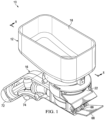
FIG. 1 depicts a perspective view of a hose-end spreader device according to exemplary embodiments. -
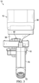
FIG. 2 depicts a front view of the hose-end spreader device ofFIG. 1 according to exemplary embodiments. -
FIG. 3 depicts a rear view of the hose-end spreader device ofFIG. 1 according to exemplary embodiments. -
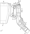
FIG. 4 depicts a left side view of the hose-end spreader device ofFIG. 1 according to exemplary embodiments. -
FIG. 5 depicts a right side view of the hose-end spreader device ofFIG. 1 according to exemplary embodiments. -
FIG. 6 depicts a top view of the hose-end spreader device ofFIG. 1 according to exemplary embodiments. -
FIG. 7 depicts a bottom view of the hose-end spreader device ofFIG. 1 according to exemplary embodiments. -
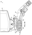
FIG. 8A depicts a cross sectional view taken along line 8-8 ofFIG. 1 with the shutter plate in an opened position according to exemplary embodiments. -
FIG. 8B depicts a cross sectional view taken along line 8-8 ofFIG. 1 with the shutter plate in a closed position according to exemplary embodiments. -
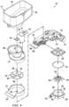
FIG. 9 depicts an exploded view of the hose-end spreader device ofFIG. 1 according to exemplary embodiments. - Hose-end spreader devices for spreading a granular product are described herein. The hose-end spreader devices is configured for broadcasting granular product and water onto a lawn, terrain, or other surface. The present devices may be attached to a hose, such as a garden hose, and movement of the fluid through the device causes the granular product to spread and/or dispense from the device. The granular product and water mix after leaving the device. The present devices may broadly be applicable to spreading any granular product, but may be particularly suitable for seeds and fertilizer.
- The term "granular product" as used herein refers to product that is particulate (or granular) in nature in that it is a dry (not liquid) product that is flowable. For example, granular product may include without limitation, seed, ice melting granules, fertilizer, pesticides, granular soil amendment material, granular oil absorbent material, dusting products, granular floor cleaning product, or any other product, as well as combinations thereof, that is dry and flowable.
- Referring to
FIGS. 1-9 , a hose-end spreader device 10 includes ahopper 12, afirst chamber 14, and ahousing 16. Thehopper 12 is configured to contain an amount of granular product and comprises ahopper inlet 18 and ahopper outlet 20 in communication with thehopper inlet 18. Thefirst chamber 14 is disposed below and is in communication with thehopper outlet 20. Thefirst chamber 14 comprises afirst opening 22 through which the granular product exits the device, and afirst impeller 24 is disposed in thefirst chamber 14. Disposed below thefirst chamber 14 is ahousing 26, which comprises afluid inlet 28, asecond chamber 30 in communication with thefluid inlet 28, and afluid outlet 32 in communication with thesecond chamber 30 through which a fluid exits thedevice 10. Asecond impeller 34 is disposed in thesecond chamber 30. Thefirst impeller 24 and thesecond impeller 34 are coupled. - In one or more embodiments, the
hopper 12 may be a unitary, monolithic structure or include multiple components making up thehopper 12 that are fixedly or removably connectable to each other. As shown inFIGS. 6 and8A , in an embodiment, thehopper 12 comprises afunnel 36, acontainer 38, and alid 39 positioned on thecontainer 38. Thelid 39 may be removed from thecontainer 38 to fill or empty thehopper 12. Thefunnel 36 andcontainer 38 are in communication with each other. The bottom surface of thecontainer 38 may be sloped to allow easier movement of the granular product towards thefunnel 36. During use of thedevice 10, granular product will move from thecontainer 38 through thefunnel 36 and into thefirst chamber 14. - In one or more embodiments, the
device 10 further includes anadjustable shutter plate 40 that is used to set an opening size of thehopper outlet 20 located at the bottom portion of thehopper 12. In the closed position, thehopper outlet 20 is closed; in the open position, at least a portion of thehopper outlet 20 is exposed. Theshutter plate 40 includes aslide channel 41. Astop 42 is positioned in the slide channel. In an embodiment, thestop 42 may also be used to couple theshutter plate 40 to thedevice 10. For example, thestop 42 may be a screw or other connector. Theshutter plate 40 is movable between a first, open position (FIG. 8A ) where thestop 42 abuts a first end of theslide channel 41 and a second, closed position (FIG. 8B ) where thestop 42 abuts the opposite end of theslide channel 41. - Additionally, in one or more embodiments, the
device 10 includes anagitator 44 disposed in thehopper 12. Theagitator 44 is coupled to arotatable shaft 46 discussed further below. In the embodiment shown, theagitator 44 has a single arm or blade. Theagitator 44 may have acurved blade 45 that is optimized for use in various granular material types used with thedevice 10. In various embodiments, theagitator 44 may have two or more arms or blades. Other agitator configurations are possible and may be optimized for use with various granular material types. In various embodiments, theagitator 44 may be changeable to allow for use of different agitator types and configurations based on the type of granular material. - Referring to
FIGS. 8A-9 , thefirst chamber 14 includes asidewall 48 extending from abottom surface 50. Thesidewall 48 may act as a deflector, which prevents granular product from being thrown, during dispensing, towards the rear of the device 10 (i.e., towards the user) or onto sidewalks, driveways, or other areas where the product is not desired. Thefirst opening 22 is at least partially defined by the ends of thesidewall 48 and thebottom surface 50. A portion of thefunnel 36 may act as an upper surface or cover for a part of thefirst chamber 14. For example, alip 51 of thefunnel 36 may partially define thefirst opening 22 and prevent the granular produce from being thrown, during dispensing, up towards thehopper 12. Thefirst chamber 14 also includes aledge 52 extending from thebottom surface 50. Theledge 52 helps prevent granular product exiting thefirst opening 22 from falling onto portions of thedevice 10 below theledge 52, such as thefluid outlet 32. In the interior of thefirst chamber 14 is thefirst impeller 24, which is positioned below thehopper outlet 20. Thefirst impeller 24 includes therotatable shaft 46 and, thus, is coupled to theagitator 44. Thefirst impeller 24 includes animpeller plate 54 and a plurality ofblades 56. Thefirst impeller 24 as shown includes fiveblades 56, although the number and shape of the blades may vary. - The
second chamber 30 in thehousing 26 is sealed to prevent fluid from entering or exiting except through thefluid inlet 28 and thefluid outlet 32. Thedevice 10 may include one or more sealing components, such as an O-ring 57. In one or more embodiments, thesecond chamber 30 may be a unitary, monolithic structure or include multiple components making up thesecond chamber 30 that are fixedly or removably connectable to each other. In the illustrated embodiment, thesecond chamber 30 includes asidewall 58 extending from abottom surface 60. Thesecond chamber 30 further includes acover 62, which forms a seal with thesidewall 58. In the interior of thesecond chamber 30 is thesecond impeller 34, which is axially aligned with thefirst impeller 24 and theagitator 44. Thesecond impeller 34 comprises ashaft 63, which is coupled to therotatable shaft 46. Accordingly, thesecond impeller 34 is coupled to thefirst impeller 24 and indirectly coupled to theagitator 44. In one or more embodiments, therotatable shaft 46 and theshaft 63 are multiple components that are fixedly or removably connectable to each other or may be a unitary, monolithic structure. Further, in one or more embodiments, thefirst impeller 24, thesecond impeller 34, and theagitator 44 may be directly or indirectly coupled to each other or may be a unitary, monolithic structure. Thesecond impeller 34 includes a plurality ofblades 64. Thesecond impeller 34 as shown includes elevenblades 64, although the number and shape of the blades may vary. In the illustrated embodiment, thefirst impeller 24 and thesecond impeller 34 are axially aligned - With further reference to
FIGS. 8A-9 , thehousing 26 further includes asecond opening 66 in communication with thefluid outlet 32. Fluid that enters thesecond chamber 30 exits thedevice 10 through thefluid outlet 32 and thesecond opening 66. Adeflector 68 extends from thehousing 26. As water exits thesecond opening 66, thedeflector 68 may cause or assist in causing the fluid to fan outwards. In other words, the width of the fluid stream increases as the fluid moves further away from thesecond opening 66. - Still referring to
FIGS. 8A-9 , thehousing 26 further includes ahandle 70, ahose connection 72, and atrigger 74. Thehandle 70 may have one or more rubber portions and a grip portion that assists with maintaining a secure grip on thehandle 70. Other suitable materials may be used. Thehose connection 72 is disposed at a rear portion of thehousing 26 and is configured to removably couple thehousing 26 to a liquid source, such as ahose 76. Thehose connection 72 is in communication with thefluid inlet 28. Thetrigger 74 is located on a lower portion of thehandle 70 but can be positioned in a variety of other locations as well. In various embodiments, a trigger lock may be included. InFIG. 8A , thetrigger 74 is depicted in a depressed state. The depressed state depicted is an operational state in which thedevice 10 is "on." When thetrigger 74 is in an "on" position, fluid may flow from thehose connection 72 to thefluid inlet 28. Thetrigger 74, when moving from an "off" to an "on" position moves inwardly toward thehousing 26. The operation of thedevice 10 is described in further detail below. - In exemplary embodiments, the
spreader device 10 is constructed of hard, durable plastic. Other suitable materials and combinations of materials may be used. - In exemplary embodiments, a method of spreading granular product is described below. The described method is exemplary as there are a variety of ways to carry out the present disclosure. First, the hopper is filled or partially filled with granular product. Next, the shutter plate is adjusted to provide the desired size of the hopper outlet. A hose or other liquid source is attached to the hose connection. Next, the trigger can then be depressed to begin operation of the device when the user is ready and spreader operation commences. Depression of the trigger allows water to flow from the hose (or other liquid source) through the fluid inlet into the second chamber. The water flowing through the second chamber causes the second impeller to rotate. Rotation of the second impeller causes rotation of the first impeller and the agitator due to the connection therebetween. The water exits the second chamber through the second opening and exits the device through the second opening. As the water exits the second opening, the deflector fans out the water. Granular product flows from the hopper, agitated by the rotating agitator, through the hopper opening at a rate permitted by the shutter plate. Then, the granular product impacts the rotating first impeller, which causes the granular product to be ejected from the device through the first opening and spread over the desired terrain. Upon completion of the desired spreading, the trigger is released and operation of the device ceases.
- In one embodiment, the granular product and the water mix together at a distance from the device. For example, the granular product and the water begin mixing when the two streams are four or more feet from the device. In one or more embodiments, the granular product and the water begin mixing when the two streams are between four and eight feet from the device.
- The foregoing description of embodiments and examples has been presented for purposes of description. It is not intended to be exhaustive or limiting to the forms described. The embodiments were chosen and described for illustration of various embodiments. It is hereby intended the scope be defined by the claims appended hereto
Claims (15)
- A hose-end spreader device (10) configured for broadcasting granular product and water onto a lawn, terrain or another surface, the device (10) comprising:a hopper (12) configured to contain an amount of granular product, the hopper (12) comprising a hopper inlet (18) and a hopper outlet (20) in communication with the hopper inlet (18);a first chamber (14) in communication with the hopper outlet (20), the first chamber (14) comprising a first opening (22) through which the granular product exits the device (10);a first impeller (24) disposed in the first chamber (14);a housing (26) disposed below the first chamber (14), the housing (26) comprising a fluid inlet (28), a second chamber (30) in communication with the fluid inlet (28), and a second opening (32) in communication with the second chamber (30) through which a fluid exits the device (10); anda second impeller (34) disposed in the second chamber (30) and being coupled to the first impeller (24).
- The device (10) of claim 1, further comprising a shaft (46, 63) extending through the first chamber (14) and the second chamber (30), the shaft (46, 63) being coupled to the first impeller (24) and the second impeller (34).
- The device (10) of claim 2, wherein the first chamber (14) and the second chamber (30) are constructed to keep the granular product separated from the fluid while inside the device (10).
- The device (10) of claim 1, wherein a diameter of the first impeller (24) is greater than a diameter of the second impeller (34).
- The device (10) of claim 1, further comprising a handle (70), wherein the second opening (32) is positioned forward of the first opening (22) relative to the handle (70).
- The device (10) of claim 1, wherein a portion of the hopper (12) is positioned forward of the first opening (22) relative to the second chamber (30).
- The device (10) of claim 3, wherein, when the fluid moves through the second chamber and exits the second opening, movement of the fluid causes rotation of the first and the second impellers, and rotation of the first impeller causes the granular product to exit the first opening, an axis of rotation of the second impeller (34) is perpendicular to a flow of the fluid through the second chamber (30).
- The device (10) of claim 3, wherein, when the fluid moves through the second chamber and exits the second opening, movement of the fluid causes rotation of the first and the second impellers, and rotation of the first impeller causes the granular product to exit the first opening, further comprising an agitator (44) disposed in the bottom portion of the hopper (12), the agitator (44) being coupled to the first impeller (24) and the second impeller (34).
- The device (10) of claim 1, further comprising a deflector (68) extending from the second opening (32) configured to cause the fluid exiting the second opening (32) to spread.
- The device (10) of claim 1, further comprising a ledge (52) extending from the first opening (22) over the second opening (32) configured to prevent the granular product from falling directly into the second opening (32).
- The device (10) of claim 1, further comprising a shutter plate (40) movably coupled to the hopper (12), the shutter plate (40) being movable between a first position where the shutter plate (40) covers the hopper outlet (20) and a second position where the shutter plate (40) is retracted and uncovers the hopper outlet (20).
- The device (10) of claim 3, wherein, when the fluid moves through the second chamber and exits the second opening, movement of the fluid causes rotation of the first and the second impellers, and rotation of the first impeller causes the granular product to exit the first opening, further comprising a handle (70) and a trigger (74) movably coupled to the handle (70), the trigger (74) being movable between a first position where fluid is prevented from entering the fluid inlet (28) and a second position where fluid is allowed to enter the fluid inlet (28).
- The device (10) of claim 12, further comprising a shutter plate (40) movably coupled to the hopper (12), the shutter plate (40) being movable between a first shutter plate position where the shutter plate (40) covers the hopper outlet (20) and a second shutter plate position where the shutter plate (40) is retracted and uncovers the hopper outlet (20),
wherein moving the trigger (74) from the first position to the second position causes the shutter plate (40) to move from the first shutter plate position to the second shutter plate position. - The device (10) of claim 13, wherein the handle (70) is configured to be removably coupled to a hose (76).
- The device (10) of claim 1, wherein:the device (10) is constructed such that a fluid flows through the fluid inlet (28) into the second chamber (30), through the second chamber (30) causing rotation of the first impeller (24) and the second impeller (34), and out the second opening (32), exiting the device (10); androtation of the first impeller (24) causes the product to dispense from the first opening (22), exiting the device (10) separate from the fluid.
Applications Claiming Priority (2)
| Application Number | Priority Date | Filing Date | Title |
|---|---|---|---|
| US201962835054P | 2019-04-17 | 2019-04-17 | |
| PCT/US2020/028403 WO2020214749A1 (en) | 2019-04-17 | 2020-04-16 | Hose-end spreader |
Publications (2)
| Publication Number | Publication Date |
|---|---|
| EP3955726A1 EP3955726A1 (en) | 2022-02-23 |
| EP3955726B1 true EP3955726B1 (en) | 2024-08-21 |
Family
ID=70682858
Family Applications (1)
| Application Number | Title | Priority Date | Filing Date |
|---|---|---|---|
| EP20725735.3A Active EP3955726B1 (en) | 2019-04-17 | 2020-04-16 | Hose-end spreader |
Country Status (8)
| Country | Link |
|---|---|
| US (1) | US12064782B2 (en) |
| EP (1) | EP3955726B1 (en) |
| JP (1) | JP7558191B2 (en) |
| CN (1) | CN113692219B (en) |
| AU (1) | AU2020257213B2 (en) |
| CA (1) | CA3136604A1 (en) |
| MX (1) | MX2021012442A (en) |
| WO (1) | WO2020214749A1 (en) |
Families Citing this family (3)
| Publication number | Priority date | Publication date | Assignee | Title |
|---|---|---|---|---|
| CN115643881A (en) * | 2022-11-18 | 2023-01-31 | 云南省德宏热带农业科学研究所 | Rubber fertilizer applicator capable of automatically proportioning fertilizer and application method thereof |
| USD1078412S1 (en) * | 2023-06-16 | 2025-06-10 | Qingdao Huatian Hand Truck Co., Ltd. | Fertilizer spreader |
| US20250386781A1 (en) * | 2024-06-24 | 2025-12-25 | Lawn and Garden, LLC | Root feeder |
Family Cites Families (67)
| Publication number | Priority date | Publication date | Assignee | Title |
|---|---|---|---|---|
| US425338A (en) * | 1890-04-08 | Distributer for flock | ||
| US2892286A (en) * | 1959-06-30 | martin | ||
| US2187376A (en) * | 1937-04-13 | 1940-01-16 | Francis W Gulbert | Spraying apparatus |
| US2740230A (en) * | 1953-04-29 | 1956-04-03 | Powerpak Equipment Company | Crop dusters |
| US3157402A (en) | 1960-10-03 | 1964-11-17 | Jr William D Love | Material spreading and broadcasting device |
| US3227461A (en) | 1964-09-28 | 1966-01-04 | Jr William D Love | Material spreading and broadcasting device |
| US3993225A (en) | 1975-09-11 | 1976-11-23 | Mario Manni | Portable spreader for particulate material |
| US4071170A (en) | 1975-12-29 | 1978-01-31 | Meiko, Inc. | Portable motor driven dusting apparatus |
| US4089441A (en) | 1976-05-24 | 1978-05-16 | Cole John M | Portable manually operated duster |
| JPS5336933A (en) * | 1976-07-01 | 1978-04-05 | Shiyunichi Akazawa | Short fiber spreader |
| US4062496A (en) | 1976-10-21 | 1977-12-13 | Conrad Melton | Spreader for particulate material |
| US4140280A (en) | 1976-10-22 | 1979-02-20 | Bermuda Research Corp. | Portable hand-held, manually-operated duster |
| US4473184A (en) | 1980-07-18 | 1984-09-25 | Hedlund Manufacturing Co., Inc. | Manure spreader |
| US4387852A (en) | 1981-09-11 | 1983-06-14 | Allegretti & Co. | Fertilizer spreader |
| US4492341A (en) | 1983-01-28 | 1985-01-08 | Bermuda Research Corp. | Portable hand-held material broadcasting device |
| USD296789S (en) | 1984-02-02 | 1988-07-19 | Linkopings Kontrollhonseri AB | Housing for manure and sludge spreader |
| US4678377A (en) | 1985-04-19 | 1987-07-07 | Bouchard Antoine J | Dispenser for particulate matter |
| JPH0623214Y2 (en) * | 1988-07-28 | 1994-06-22 | 株式会社向井工業 | Electric granulator |
| US5271568A (en) | 1988-12-29 | 1993-12-21 | Stevie Charles R | Spreader device |
| US5054693A (en) | 1990-06-19 | 1991-10-08 | Jessie Chow | Portable distributor for seeds or fertilizer |
| US5123598A (en) | 1990-08-07 | 1992-06-23 | The O. M. Scott & Sons Company, Inc. | Portable spreading devices |
| USD333951S (en) | 1990-08-07 | 1993-03-16 | The O.M. Scott & Sons Company | Portable spreader |
| JPH0452412U (en) * | 1990-09-10 | 1992-05-01 | ||
| USD327823S (en) | 1990-09-20 | 1992-07-14 | S. C. Johnson & Son, Inc. | Material spreader |
| US5119993A (en) | 1990-10-29 | 1992-06-09 | S. C. Johnson & Son, Inc. | Portable particulate material spreader |
| US5285971A (en) | 1993-01-19 | 1994-02-15 | Republic Tool & Mfg. Corp. | Hand held spreader |
| US5409166A (en) * | 1993-06-02 | 1995-04-25 | Natural Earth Technologies, Inc. | Battery-powered particulate spreader |
| US5333795A (en) | 1993-10-21 | 1994-08-02 | Jessen Thomas F | Granular and liquid treatment material spreader |
| US5429278A (en) | 1994-05-09 | 1995-07-04 | Sansalone; Dominic A. | Portable garden powder duster |
| USD387638S (en) | 1996-07-08 | 1997-12-16 | Republic Tool & Mfg. Corp. | Hand held spreader |
| USD388440S (en) | 1996-09-06 | 1997-12-30 | Bentley John A | Self-loading material spreader |
| US6024294A (en) | 1998-06-03 | 2000-02-15 | Dillon; Patrick | Portable spreader |
| US6089477A (en) * | 1999-01-04 | 2000-07-18 | Dillon; Patrick | Backpack spreader |
| US6092746A (en) | 1999-03-22 | 2000-07-25 | Dillon; Patrick | Portable particulate spreader |
| US6425500B2 (en) | 1999-06-18 | 2002-07-30 | Mcnally Brian G. | Hand held salt dispensing device |
| US6840468B2 (en) | 2001-03-29 | 2005-01-11 | Wade C. Barnett | Salt shooter |
| US6616074B2 (en) | 2001-05-02 | 2003-09-09 | Oms Investments, Inc. | Broadcast spreader with movable deflector |
| US6729557B2 (en) | 2002-06-03 | 2004-05-04 | Patrick Dillon | Particulate spreader |
| US7328861B2 (en) | 2004-07-20 | 2008-02-12 | Keter Plastic Ltd | Particulate material spreader |
| US7837073B2 (en) | 2005-01-14 | 2010-11-23 | Oms Investments, Inc. | Collapsible spreader |
| USD534044S1 (en) | 2005-01-28 | 2006-12-26 | Keter Plastic Ltd. | Particulate material spreader |
| CN2781741Y (en) | 2005-04-20 | 2006-05-24 | 吉林农业大学 | Small-size hand self-running organic fertilizer applicator |
| US20070194155A1 (en) | 2005-07-18 | 2007-08-23 | Kendall Jeffrey D | Broadcast spreader with rate control system |
| US7281675B2 (en) | 2005-08-15 | 2007-10-16 | Marcos Elrod | Portable particle spreader/blower |
| CN201064099Y (en) | 2007-06-26 | 2008-05-28 | 陈仙根 | Fertilizer applicator |
| US8104648B2 (en) | 2007-10-22 | 2012-01-31 | The Fountainhead Group, Inc. | Mixing applicator |
| CN201207808Y (en) | 2008-01-04 | 2009-03-18 | 常青树农机制品(北京)有限公司 | Electric seeding device |
| US8757521B2 (en) | 2008-05-09 | 2014-06-24 | Oms Investments, Inc. | Cartridge spreader system |
| CN201398353Y (en) * | 2009-04-20 | 2010-02-10 | 杨征林 | A fertilization tank matched with drip irrigation |
| WO2011057205A2 (en) | 2009-11-06 | 2011-05-12 | The Andersons, Inc. | Hose attachment particulate spreader |
| US20110297763A1 (en) | 2010-06-06 | 2011-12-08 | Kressy Matthew S | Portable spreader for particulate matter |
| US20130001332A1 (en) | 2011-06-29 | 2013-01-03 | Marconi Jr Fred A | Electrically-powered spreader |
| CN202354058U (en) | 2011-10-21 | 2012-08-01 | 高阳 | Solid fertilizer spreading machine |
| US9222231B2 (en) | 2013-03-15 | 2015-12-29 | Fred Marconi | Electrically powered hand spreader |
| US9458585B2 (en) * | 2014-04-04 | 2016-10-04 | The Toro Company | Leakproof spreader device |
| USD744303S1 (en) | 2014-04-23 | 2015-12-01 | Fred Marconi | Handheld particulate spreader |
| ES2757963T3 (en) * | 2014-12-30 | 2020-04-30 | Maschio Gaspardo Spa | Centrifugal disperser for fertilizer and manure |
| ES2780027T3 (en) * | 2014-12-30 | 2020-08-21 | Maschio Gaspardo Spa | A centrifugal spreader for fertilizers and manures |
| CN204762121U (en) * | 2015-06-11 | 2015-11-18 | 杨洁 | Forest adds moisture and contains water installation |
| EP3850934B1 (en) | 2015-08-20 | 2024-03-20 | OMS Investments, Inc. | Power hand-held spreader |
| USD796922S1 (en) | 2015-08-20 | 2017-09-12 | Oms Investments, Inc. | Powered hand-held spreader |
| US10743459B2 (en) | 2016-01-19 | 2020-08-18 | Chapin Manufacturing, Inc. | Hand-held spreader |
| CN106837811B (en) * | 2017-01-24 | 2022-10-04 | 江苏星隆环保科技有限公司 | Submersible stirring system based on water turbine |
| USD834901S1 (en) | 2017-05-05 | 2018-12-04 | Chapin Manufacturing, Inc. | Hand-held spreader |
| USD823655S1 (en) | 2017-05-05 | 2018-07-24 | Chapin Manufacturing, Inc. | Hand-held spreader |
| CN208624096U (en) * | 2018-06-28 | 2019-03-22 | 黑龙江省水田机械化研究所 | Paddy field granular base fertilizer spreader |
| CN108770448A (en) * | 2018-07-05 | 2018-11-09 | 梁玉燕 | A kind of farmland planting granulo-fertilizer sowing apparatus |
-
2020
- 2020-04-16 JP JP2021560949A patent/JP7558191B2/en active Active
- 2020-04-16 CN CN202080029076.0A patent/CN113692219B/en active Active
- 2020-04-16 MX MX2021012442A patent/MX2021012442A/en unknown
- 2020-04-16 AU AU2020257213A patent/AU2020257213B2/en active Active
- 2020-04-16 US US17/604,071 patent/US12064782B2/en active Active
- 2020-04-16 WO PCT/US2020/028403 patent/WO2020214749A1/en not_active Ceased
- 2020-04-16 EP EP20725735.3A patent/EP3955726B1/en active Active
- 2020-04-16 CA CA3136604A patent/CA3136604A1/en active Pending
Also Published As
| Publication number | Publication date |
|---|---|
| WO2020214749A1 (en) | 2020-10-22 |
| CN113692219B (en) | 2024-02-02 |
| AU2020257213A1 (en) | 2021-11-11 |
| MX2021012442A (en) | 2021-11-04 |
| CA3136604A1 (en) | 2020-10-22 |
| AU2020257213B2 (en) | 2025-10-02 |
| US20220152637A1 (en) | 2022-05-19 |
| JP7558191B2 (en) | 2024-09-30 |
| US12064782B2 (en) | 2024-08-20 |
| CN113692219A (en) | 2021-11-23 |
| JP2022528989A (en) | 2022-06-16 |
| EP3955726A1 (en) | 2022-02-23 |
Similar Documents
| Publication | Publication Date | Title |
|---|---|---|
| AU2020257213B2 (en) | Hose-end spreader | |
| AU2002311910B2 (en) | Broadcast spreader with movable deflector | |
| CN102076208B (en) | Cartridge spreader system | |
| US20030057303A1 (en) | Dual mode spreader | |
| US6089477A (en) | Backpack spreader | |
| AU2002311910A1 (en) | Broadcast spreader with movable deflector | |
| US20160345488A1 (en) | Spreader Attachment | |
| US20150115072A1 (en) | Spreader Attachment | |
| US6113003A (en) | Compressed air duster with rotatable agitator | |
| UA80434C2 (en) | Seeding machine | |
| HK40070077B (en) | Hose-end spreader | |
| HK40070077A (en) | Hose-end spreader | |
| KR101111147B1 (en) | Fertilizer spreading device for tractor using GPS | |
| US7086616B2 (en) | Broadcast spreader attachment for hand-held gas or electric leaf blowers | |
| CN110022669B (en) | Hand-held device for spreading materials | |
| US3330445A (en) | Hand duster | |
| JP4089548B2 (en) | Powder and particle feeding device | |
| US20130092748A1 (en) | Hose attachment particulate spreader | |
| GB2406322A (en) | Spreader for particulate material | |
| HU188338B (en) | Equipment for charing agricultural chemical products of solid state | |
| WO2018095586A1 (en) | Handheld apparatus for spreading material | |
| US1716970A (en) | Method and apparatus for dusting insecticide and fungicide powders upon plants | |
| IE85122B1 (en) | Horticultural spreader | |
| CN106982655B (en) | Hand-held type scattering device | |
| JPH10235239A (en) | Granule applicator |
Legal Events
| Date | Code | Title | Description |
|---|---|---|---|
| STAA | Information on the status of an ep patent application or granted ep patent |
Free format text: STATUS: UNKNOWN |
|
| STAA | Information on the status of an ep patent application or granted ep patent |
Free format text: STATUS: THE INTERNATIONAL PUBLICATION HAS BEEN MADE |
|
| PUAI | Public reference made under article 153(3) epc to a published international application that has entered the european phase |
Free format text: ORIGINAL CODE: 0009012 |
|
| STAA | Information on the status of an ep patent application or granted ep patent |
Free format text: STATUS: REQUEST FOR EXAMINATION WAS MADE |
|
| 17P | Request for examination filed |
Effective date: 20211105 |
|
| AK | Designated contracting states |
Kind code of ref document: A1 Designated state(s): AL AT BE BG CH CY CZ DE DK EE ES FI FR GB GR HR HU IE IS IT LI LT LU LV MC MK MT NL NO PL PT RO RS SE SI SK SM TR |
|
| DAV | Request for validation of the european patent (deleted) | ||
| DAX | Request for extension of the european patent (deleted) | ||
| REG | Reference to a national code |
Ref country code: HK Ref legal event code: DE Ref document number: 40070077 Country of ref document: HK |
|
| REG | Reference to a national code |
Ref legal event code: R079 Ipc: B05B0015250000 Ref country code: DE Ref legal event code: R079 Ref document number: 602020036190 Country of ref document: DE Free format text: PREVIOUS MAIN CLASS: A01C0023040000 Ipc: B05B0015250000 |
|
| RIC1 | Information provided on ipc code assigned before grant |
Ipc: A01C 15/00 20060101ALN20231002BHEP Ipc: A01C 15/02 20060101ALI20231002BHEP Ipc: A01C 7/02 20060101ALI20231002BHEP Ipc: A01C 23/04 20060101ALI20231002BHEP Ipc: B05B 7/14 20060101ALI20231002BHEP Ipc: B05B 15/25 20180101AFI20231002BHEP |
|
| GRAP | Despatch of communication of intention to grant a patent |
Free format text: ORIGINAL CODE: EPIDOSNIGR1 |
|
| STAA | Information on the status of an ep patent application or granted ep patent |
Free format text: STATUS: GRANT OF PATENT IS INTENDED |
|
| RIC1 | Information provided on ipc code assigned before grant |
Ipc: A01C 15/00 20060101ALN20231013BHEP Ipc: A01C 15/02 20060101ALI20231013BHEP Ipc: A01C 7/02 20060101ALI20231013BHEP Ipc: A01C 23/04 20060101ALI20231013BHEP Ipc: B05B 7/14 20060101ALI20231013BHEP Ipc: B05B 15/25 20180101AFI20231013BHEP |
|
| INTG | Intention to grant announced |
Effective date: 20231110 |
|
| GRAJ | Information related to disapproval of communication of intention to grant by the applicant or resumption of examination proceedings by the epo deleted |
Free format text: ORIGINAL CODE: EPIDOSDIGR1 |
|
| STAA | Information on the status of an ep patent application or granted ep patent |
Free format text: STATUS: REQUEST FOR EXAMINATION WAS MADE |
|
| GRAP | Despatch of communication of intention to grant a patent |
Free format text: ORIGINAL CODE: EPIDOSNIGR1 |
|
| STAA | Information on the status of an ep patent application or granted ep patent |
Free format text: STATUS: GRANT OF PATENT IS INTENDED |
|
| INTC | Intention to grant announced (deleted) | ||
| INTG | Intention to grant announced |
Effective date: 20240402 |
|
| RIC1 | Information provided on ipc code assigned before grant |
Ipc: A01C 15/00 20060101ALN20240319BHEP Ipc: A01C 15/02 20060101ALI20240319BHEP Ipc: A01C 7/02 20060101ALI20240319BHEP Ipc: A01C 23/04 20060101ALI20240319BHEP Ipc: B05B 7/14 20060101ALI20240319BHEP Ipc: B05B 15/25 20180101AFI20240319BHEP |
|
| GRAS | Grant fee paid |
Free format text: ORIGINAL CODE: EPIDOSNIGR3 |
|
| GRAA | (expected) grant |
Free format text: ORIGINAL CODE: 0009210 |
|
| STAA | Information on the status of an ep patent application or granted ep patent |
Free format text: STATUS: THE PATENT HAS BEEN GRANTED |
|
| AK | Designated contracting states |
Kind code of ref document: B1 Designated state(s): AL AT BE BG CH CY CZ DE DK EE ES FI FR GB GR HR HU IE IS IT LI LT LU LV MC MK MT NL NO PL PT RO RS SE SI SK SM TR |
|
| REG | Reference to a national code |
Ref country code: GB Ref legal event code: FG4D |
|
| REG | Reference to a national code |
Ref country code: CH Ref legal event code: EP |
|
| REG | Reference to a national code |
Ref country code: IE Ref legal event code: FG4D |
|
| REG | Reference to a national code |
Ref country code: DE Ref legal event code: R096 Ref document number: 602020036190 Country of ref document: DE |
|
| REG | Reference to a national code |
Ref country code: LT Ref legal event code: MG9D |
|
| REG | Reference to a national code |
Ref country code: NL Ref legal event code: MP Effective date: 20240821 |
|
| PG25 | Lapsed in a contracting state [announced via postgrant information from national office to epo] |
Ref country code: NO Free format text: LAPSE BECAUSE OF FAILURE TO SUBMIT A TRANSLATION OF THE DESCRIPTION OR TO PAY THE FEE WITHIN THE PRESCRIBED TIME-LIMIT Effective date: 20241121 |
|
| REG | Reference to a national code |
Ref country code: AT Ref legal event code: MK05 Ref document number: 1715030 Country of ref document: AT Kind code of ref document: T Effective date: 20240821 |
|
| PG25 | Lapsed in a contracting state [announced via postgrant information from national office to epo] |
Ref country code: NL Free format text: LAPSE BECAUSE OF FAILURE TO SUBMIT A TRANSLATION OF THE DESCRIPTION OR TO PAY THE FEE WITHIN THE PRESCRIBED TIME-LIMIT Effective date: 20240821 Ref country code: FI Free format text: LAPSE BECAUSE OF FAILURE TO SUBMIT A TRANSLATION OF THE DESCRIPTION OR TO PAY THE FEE WITHIN THE PRESCRIBED TIME-LIMIT Effective date: 20240821 Ref country code: PL Free format text: LAPSE BECAUSE OF FAILURE TO SUBMIT A TRANSLATION OF THE DESCRIPTION OR TO PAY THE FEE WITHIN THE PRESCRIBED TIME-LIMIT Effective date: 20240821 Ref country code: GR Free format text: LAPSE BECAUSE OF FAILURE TO SUBMIT A TRANSLATION OF THE DESCRIPTION OR TO PAY THE FEE WITHIN THE PRESCRIBED TIME-LIMIT Effective date: 20241122 Ref country code: PT Free format text: LAPSE BECAUSE OF FAILURE TO SUBMIT A TRANSLATION OF THE DESCRIPTION OR TO PAY THE FEE WITHIN THE PRESCRIBED TIME-LIMIT Effective date: 20241223 |
|
| PG25 | Lapsed in a contracting state [announced via postgrant information from national office to epo] |
Ref country code: BG Free format text: LAPSE BECAUSE OF FAILURE TO SUBMIT A TRANSLATION OF THE DESCRIPTION OR TO PAY THE FEE WITHIN THE PRESCRIBED TIME-LIMIT Effective date: 20240821 |
|
| PG25 | Lapsed in a contracting state [announced via postgrant information from national office to epo] |
Ref country code: LV Free format text: LAPSE BECAUSE OF FAILURE TO SUBMIT A TRANSLATION OF THE DESCRIPTION OR TO PAY THE FEE WITHIN THE PRESCRIBED TIME-LIMIT Effective date: 20240821 |
|
| PG25 | Lapsed in a contracting state [announced via postgrant information from national office to epo] |
Ref country code: AT Free format text: LAPSE BECAUSE OF FAILURE TO SUBMIT A TRANSLATION OF THE DESCRIPTION OR TO PAY THE FEE WITHIN THE PRESCRIBED TIME-LIMIT Effective date: 20240821 Ref country code: IS Free format text: LAPSE BECAUSE OF FAILURE TO SUBMIT A TRANSLATION OF THE DESCRIPTION OR TO PAY THE FEE WITHIN THE PRESCRIBED TIME-LIMIT Effective date: 20241221 |
|
| PG25 | Lapsed in a contracting state [announced via postgrant information from national office to epo] |
Ref country code: HR Free format text: LAPSE BECAUSE OF FAILURE TO SUBMIT A TRANSLATION OF THE DESCRIPTION OR TO PAY THE FEE WITHIN THE PRESCRIBED TIME-LIMIT Effective date: 20240821 |
|
| PG25 | Lapsed in a contracting state [announced via postgrant information from national office to epo] |
Ref country code: RS Free format text: LAPSE BECAUSE OF FAILURE TO SUBMIT A TRANSLATION OF THE DESCRIPTION OR TO PAY THE FEE WITHIN THE PRESCRIBED TIME-LIMIT Effective date: 20241121 Ref country code: ES Free format text: LAPSE BECAUSE OF FAILURE TO SUBMIT A TRANSLATION OF THE DESCRIPTION OR TO PAY THE FEE WITHIN THE PRESCRIBED TIME-LIMIT Effective date: 20240821 |
|
| PG25 | Lapsed in a contracting state [announced via postgrant information from national office to epo] |
Ref country code: RS Free format text: LAPSE BECAUSE OF FAILURE TO SUBMIT A TRANSLATION OF THE DESCRIPTION OR TO PAY THE FEE WITHIN THE PRESCRIBED TIME-LIMIT Effective date: 20241121 Ref country code: PT Free format text: LAPSE BECAUSE OF FAILURE TO SUBMIT A TRANSLATION OF THE DESCRIPTION OR TO PAY THE FEE WITHIN THE PRESCRIBED TIME-LIMIT Effective date: 20241223 Ref country code: PL Free format text: LAPSE BECAUSE OF FAILURE TO SUBMIT A TRANSLATION OF THE DESCRIPTION OR TO PAY THE FEE WITHIN THE PRESCRIBED TIME-LIMIT Effective date: 20240821 Ref country code: NO Free format text: LAPSE BECAUSE OF FAILURE TO SUBMIT A TRANSLATION OF THE DESCRIPTION OR TO PAY THE FEE WITHIN THE PRESCRIBED TIME-LIMIT Effective date: 20241121 Ref country code: NL Free format text: LAPSE BECAUSE OF FAILURE TO SUBMIT A TRANSLATION OF THE DESCRIPTION OR TO PAY THE FEE WITHIN THE PRESCRIBED TIME-LIMIT Effective date: 20240821 Ref country code: LV Free format text: LAPSE BECAUSE OF FAILURE TO SUBMIT A TRANSLATION OF THE DESCRIPTION OR TO PAY THE FEE WITHIN THE PRESCRIBED TIME-LIMIT Effective date: 20240821 Ref country code: IS Free format text: LAPSE BECAUSE OF FAILURE TO SUBMIT A TRANSLATION OF THE DESCRIPTION OR TO PAY THE FEE WITHIN THE PRESCRIBED TIME-LIMIT Effective date: 20241221 Ref country code: HR Free format text: LAPSE BECAUSE OF FAILURE TO SUBMIT A TRANSLATION OF THE DESCRIPTION OR TO PAY THE FEE WITHIN THE PRESCRIBED TIME-LIMIT Effective date: 20240821 Ref country code: GR Free format text: LAPSE BECAUSE OF FAILURE TO SUBMIT A TRANSLATION OF THE DESCRIPTION OR TO PAY THE FEE WITHIN THE PRESCRIBED TIME-LIMIT Effective date: 20241122 Ref country code: FI Free format text: LAPSE BECAUSE OF FAILURE TO SUBMIT A TRANSLATION OF THE DESCRIPTION OR TO PAY THE FEE WITHIN THE PRESCRIBED TIME-LIMIT Effective date: 20240821 Ref country code: ES Free format text: LAPSE BECAUSE OF FAILURE TO SUBMIT A TRANSLATION OF THE DESCRIPTION OR TO PAY THE FEE WITHIN THE PRESCRIBED TIME-LIMIT Effective date: 20240821 Ref country code: BG Free format text: LAPSE BECAUSE OF FAILURE TO SUBMIT A TRANSLATION OF THE DESCRIPTION OR TO PAY THE FEE WITHIN THE PRESCRIBED TIME-LIMIT Effective date: 20240821 Ref country code: AT Free format text: LAPSE BECAUSE OF FAILURE TO SUBMIT A TRANSLATION OF THE DESCRIPTION OR TO PAY THE FEE WITHIN THE PRESCRIBED TIME-LIMIT Effective date: 20240821 |
|
| PG25 | Lapsed in a contracting state [announced via postgrant information from national office to epo] |
Ref country code: DK Free format text: LAPSE BECAUSE OF FAILURE TO SUBMIT A TRANSLATION OF THE DESCRIPTION OR TO PAY THE FEE WITHIN THE PRESCRIBED TIME-LIMIT Effective date: 20240821 Ref country code: SM Free format text: LAPSE BECAUSE OF FAILURE TO SUBMIT A TRANSLATION OF THE DESCRIPTION OR TO PAY THE FEE WITHIN THE PRESCRIBED TIME-LIMIT Effective date: 20240821 Ref country code: RO Free format text: LAPSE BECAUSE OF FAILURE TO SUBMIT A TRANSLATION OF THE DESCRIPTION OR TO PAY THE FEE WITHIN THE PRESCRIBED TIME-LIMIT Effective date: 20240821 |
|
| PG25 | Lapsed in a contracting state [announced via postgrant information from national office to epo] |
Ref country code: EE Free format text: LAPSE BECAUSE OF FAILURE TO SUBMIT A TRANSLATION OF THE DESCRIPTION OR TO PAY THE FEE WITHIN THE PRESCRIBED TIME-LIMIT Effective date: 20240821 |
|
| PG25 | Lapsed in a contracting state [announced via postgrant information from national office to epo] |
Ref country code: CZ Free format text: LAPSE BECAUSE OF FAILURE TO SUBMIT A TRANSLATION OF THE DESCRIPTION OR TO PAY THE FEE WITHIN THE PRESCRIBED TIME-LIMIT Effective date: 20240821 |
|
| PG25 | Lapsed in a contracting state [announced via postgrant information from national office to epo] |
Ref country code: IT Free format text: LAPSE BECAUSE OF FAILURE TO SUBMIT A TRANSLATION OF THE DESCRIPTION OR TO PAY THE FEE WITHIN THE PRESCRIBED TIME-LIMIT Effective date: 20240821 Ref country code: SK Free format text: LAPSE BECAUSE OF FAILURE TO SUBMIT A TRANSLATION OF THE DESCRIPTION OR TO PAY THE FEE WITHIN THE PRESCRIBED TIME-LIMIT Effective date: 20240821 |
|
| REG | Reference to a national code |
Ref country code: DE Ref legal event code: R097 Ref document number: 602020036190 Country of ref document: DE |
|
| PLBE | No opposition filed within time limit |
Free format text: ORIGINAL CODE: 0009261 |
|
| STAA | Information on the status of an ep patent application or granted ep patent |
Free format text: STATUS: NO OPPOSITION FILED WITHIN TIME LIMIT |
|
| PGFP | Annual fee paid to national office [announced via postgrant information from national office to epo] |
Ref country code: DE Payment date: 20250429 Year of fee payment: 6 |
|
| PGFP | Annual fee paid to national office [announced via postgrant information from national office to epo] |
Ref country code: GB Payment date: 20250428 Year of fee payment: 6 |
|
| PGFP | Annual fee paid to national office [announced via postgrant information from national office to epo] |
Ref country code: FR Payment date: 20250425 Year of fee payment: 6 |
|
| 26N | No opposition filed |
Effective date: 20250522 |
|
| PG25 | Lapsed in a contracting state [announced via postgrant information from national office to epo] |
Ref country code: SE Free format text: LAPSE BECAUSE OF FAILURE TO SUBMIT A TRANSLATION OF THE DESCRIPTION OR TO PAY THE FEE WITHIN THE PRESCRIBED TIME-LIMIT Effective date: 20240821 |
|
| REG | Reference to a national code |
Ref country code: CH Ref legal event code: H13 Free format text: ST27 STATUS EVENT CODE: U-0-0-H10-H13 (AS PROVIDED BY THE NATIONAL OFFICE) Effective date: 20251125 |
|
| PG25 | Lapsed in a contracting state [announced via postgrant information from national office to epo] |
Ref country code: LU Free format text: LAPSE BECAUSE OF NON-PAYMENT OF DUE FEES Effective date: 20250416 |
|
| PG25 | Lapsed in a contracting state [announced via postgrant information from national office to epo] |
Ref country code: MC Free format text: LAPSE BECAUSE OF FAILURE TO SUBMIT A TRANSLATION OF THE DESCRIPTION OR TO PAY THE FEE WITHIN THE PRESCRIBED TIME-LIMIT Effective date: 20240821 |
|
| REG | Reference to a national code |
Ref country code: BE Ref legal event code: MM Effective date: 20250430 |
|
| PG25 | Lapsed in a contracting state [announced via postgrant information from national office to epo] |
Ref country code: BE Free format text: LAPSE BECAUSE OF NON-PAYMENT OF DUE FEES Effective date: 20250430 |
|
| PG25 | Lapsed in a contracting state [announced via postgrant information from national office to epo] |
Ref country code: CH Free format text: LAPSE BECAUSE OF NON-PAYMENT OF DUE FEES Effective date: 20250430 |
|
| PG25 | Lapsed in a contracting state [announced via postgrant information from national office to epo] |
Ref country code: IE Free format text: LAPSE BECAUSE OF NON-PAYMENT OF DUE FEES Effective date: 20250416 |