EP3955593A1 - Hörgerät mit mikrofonschaltung und entsprechendes verfahren - Google Patents
Hörgerät mit mikrofonschaltung und entsprechendes verfahren Download PDFInfo
- Publication number
- EP3955593A1 EP3955593A1 EP21185272.8A EP21185272A EP3955593A1 EP 3955593 A1 EP3955593 A1 EP 3955593A1 EP 21185272 A EP21185272 A EP 21185272A EP 3955593 A1 EP3955593 A1 EP 3955593A1
- Authority
- EP
- European Patent Office
- Prior art keywords
- primary
- mixer
- input
- microphone
- output
- Prior art date
- Legal status (The legal status is an assumption and is not a legal conclusion. Google has not performed a legal analysis and makes no representation as to the accuracy of the status listed.)
- Pending
Links
- 238000000034 method Methods 0.000 title claims abstract description 75
- 210000000613 ear canal Anatomy 0.000 claims description 7
- 239000004020 conductor Substances 0.000 description 8
- 230000008447 perception Effects 0.000 description 7
- 230000008901 benefit Effects 0.000 description 5
- 230000003044 adaptive effect Effects 0.000 description 4
- 230000008859 change Effects 0.000 description 4
- 238000010586 diagram Methods 0.000 description 4
- 230000006870 function Effects 0.000 description 4
- 206010011878 Deafness Diseases 0.000 description 2
- 238000001514 detection method Methods 0.000 description 2
- 238000001914 filtration Methods 0.000 description 2
- 210000003128 head Anatomy 0.000 description 2
- 230000010370 hearing loss Effects 0.000 description 2
- 231100000888 hearing loss Toxicity 0.000 description 2
- 208000016354 hearing loss disease Diseases 0.000 description 2
- 238000002372 labelling Methods 0.000 description 2
- 238000012986 modification Methods 0.000 description 2
- 230000004048 modification Effects 0.000 description 2
- 238000007781 pre-processing Methods 0.000 description 2
- 230000008569 process Effects 0.000 description 2
- 230000000295 complement effect Effects 0.000 description 1
- 238000004590 computer program Methods 0.000 description 1
- 230000001934 delay Effects 0.000 description 1
- 230000000694 effects Effects 0.000 description 1
- 230000009467 reduction Effects 0.000 description 1
- 230000002123 temporal effect Effects 0.000 description 1
Images

Classifications
-
- H—ELECTRICITY
- H04—ELECTRIC COMMUNICATION TECHNIQUE
- H04R—LOUDSPEAKERS, MICROPHONES, GRAMOPHONE PICK-UPS OR LIKE ACOUSTIC ELECTROMECHANICAL TRANSDUCERS; DEAF-AID SETS; PUBLIC ADDRESS SYSTEMS
- H04R25/00—Deaf-aid sets, i.e. electro-acoustic or electro-mechanical hearing aids; Electric tinnitus maskers providing an auditory perception
- H04R25/40—Arrangements for obtaining a desired directivity characteristic
- H04R25/407—Circuits for combining signals of a plurality of transducers
-
- H—ELECTRICITY
- H04—ELECTRIC COMMUNICATION TECHNIQUE
- H04R—LOUDSPEAKERS, MICROPHONES, GRAMOPHONE PICK-UPS OR LIKE ACOUSTIC ELECTROMECHANICAL TRANSDUCERS; DEAF-AID SETS; PUBLIC ADDRESS SYSTEMS
- H04R3/00—Circuits for transducers, loudspeakers or microphones
- H04R3/005—Circuits for transducers, loudspeakers or microphones for combining the signals of two or more microphones
-
- H—ELECTRICITY
- H04—ELECTRIC COMMUNICATION TECHNIQUE
- H04R—LOUDSPEAKERS, MICROPHONES, GRAMOPHONE PICK-UPS OR LIKE ACOUSTIC ELECTROMECHANICAL TRANSDUCERS; DEAF-AID SETS; PUBLIC ADDRESS SYSTEMS
- H04R25/00—Deaf-aid sets, i.e. electro-acoustic or electro-mechanical hearing aids; Electric tinnitus maskers providing an auditory perception
- H04R25/65—Housing parts, e.g. shells, tips or moulds, or their manufacture
-
- H—ELECTRICITY
- H04—ELECTRIC COMMUNICATION TECHNIQUE
- H04R—LOUDSPEAKERS, MICROPHONES, GRAMOPHONE PICK-UPS OR LIKE ACOUSTIC ELECTROMECHANICAL TRANSDUCERS; DEAF-AID SETS; PUBLIC ADDRESS SYSTEMS
- H04R25/00—Deaf-aid sets, i.e. electro-acoustic or electro-mechanical hearing aids; Electric tinnitus maskers providing an auditory perception
- H04R25/43—Electronic input selection or mixing based on input signal analysis, e.g. mixing or selection between microphone and telecoil or between microphones with different directivity characteristics
-
- H—ELECTRICITY
- H04—ELECTRIC COMMUNICATION TECHNIQUE
- H04R—LOUDSPEAKERS, MICROPHONES, GRAMOPHONE PICK-UPS OR LIKE ACOUSTIC ELECTROMECHANICAL TRANSDUCERS; DEAF-AID SETS; PUBLIC ADDRESS SYSTEMS
- H04R25/00—Deaf-aid sets, i.e. electro-acoustic or electro-mechanical hearing aids; Electric tinnitus maskers providing an auditory perception
- H04R25/60—Mounting or interconnection of hearing aid parts, e.g. inside tips, housings or to ossicles
- H04R25/604—Mounting or interconnection of hearing aid parts, e.g. inside tips, housings or to ossicles of acoustic or vibrational transducers
-
- H—ELECTRICITY
- H04—ELECTRIC COMMUNICATION TECHNIQUE
- H04R—LOUDSPEAKERS, MICROPHONES, GRAMOPHONE PICK-UPS OR LIKE ACOUSTIC ELECTROMECHANICAL TRANSDUCERS; DEAF-AID SETS; PUBLIC ADDRESS SYSTEMS
- H04R25/00—Deaf-aid sets, i.e. electro-acoustic or electro-mechanical hearing aids; Electric tinnitus maskers providing an auditory perception
- H04R25/60—Mounting or interconnection of hearing aid parts, e.g. inside tips, housings or to ossicles
- H04R25/609—Mounting or interconnection of hearing aid parts, e.g. inside tips, housings or to ossicles of circuitry
-
- H—ELECTRICITY
- H04—ELECTRIC COMMUNICATION TECHNIQUE
- H04R—LOUDSPEAKERS, MICROPHONES, GRAMOPHONE PICK-UPS OR LIKE ACOUSTIC ELECTROMECHANICAL TRANSDUCERS; DEAF-AID SETS; PUBLIC ADDRESS SYSTEMS
- H04R2225/00—Details of deaf aids covered by H04R25/00, not provided for in any of its subgroups
- H04R2225/021—Behind the ear [BTE] hearing aids
- H04R2225/0216—BTE hearing aids having a receiver in the ear mould
-
- H—ELECTRICITY
- H04—ELECTRIC COMMUNICATION TECHNIQUE
- H04R—LOUDSPEAKERS, MICROPHONES, GRAMOPHONE PICK-UPS OR LIKE ACOUSTIC ELECTROMECHANICAL TRANSDUCERS; DEAF-AID SETS; PUBLIC ADDRESS SYSTEMS
- H04R2225/00—Details of deaf aids covered by H04R25/00, not provided for in any of its subgroups
- H04R2225/025—In the ear hearing aids [ITE] hearing aids
-
- H—ELECTRICITY
- H04—ELECTRIC COMMUNICATION TECHNIQUE
- H04R—LOUDSPEAKERS, MICROPHONES, GRAMOPHONE PICK-UPS OR LIKE ACOUSTIC ELECTROMECHANICAL TRANSDUCERS; DEAF-AID SETS; PUBLIC ADDRESS SYSTEMS
- H04R2225/00—Details of deaf aids covered by H04R25/00, not provided for in any of its subgroups
- H04R2225/43—Signal processing in hearing aids to enhance the speech intelligibility
-
- H—ELECTRICITY
- H04—ELECTRIC COMMUNICATION TECHNIQUE
- H04R—LOUDSPEAKERS, MICROPHONES, GRAMOPHONE PICK-UPS OR LIKE ACOUSTIC ELECTROMECHANICAL TRANSDUCERS; DEAF-AID SETS; PUBLIC ADDRESS SYSTEMS
- H04R2225/00—Details of deaf aids covered by H04R25/00, not provided for in any of its subgroups
- H04R2225/61—Aspects relating to mechanical or electronic switches or control elements, e.g. functioning
Definitions
- the present disclosure relates to a hearing device and related methods including a method of operating a hearing device.
- a hearing device with both an in-ear microphone and one or more behind-the-ear microphones and related method are disclosed.
- a hearing device comprising a first housing configured as a behind-the-ear housing to be worn behind the pinna of a user; a second housing configured as an earpiece housing to be worn in or at the ear canal of a user; a wire connecting the first housing and the second housing; a primary set of microphones arranged in the first housing, the primary set of microphones including a primary first microphone for provision of a primary first microphone input signal, and a primary second microphone for provision of a primary second microphone input signal; a secondary microphone arranged in the second housing for provision of a secondary microphone input signal; a mixing module for provision of a mixer output based on a primary mixer input and a secondary mixer input, wherein the primary mixer input optionally is based on the primary first microphone input signal and/or the primary second microphone input signal, and the secondary mixer input is based on the secondary microphone input signal; a mixing controller configured to control the mixing module; a processor for processing the mixer output and providing an electrical output signal based on mixer output; and a receiver for
- the mixing controller is optionally configured to determine presence of a switch event, such as a sound event, and in accordance with a determination that a sound event is present, control the mixing module, such as increase an amount of the secondary mixer input in the mixer output for a time period and/or reduce the amount of the secondary mixer input in the mixer output after the time period.
- a switch event such as a sound event
- a method of operating a hearing device comprising a first housing configured as a behind-the-ear housing to be worn behind the pinna of a user; a second housing configured as an earpiece housing to be worn in or at the ear canal of a user; a wire connecting the first housing and the second housing; a primary set of microphones arranged in the first housing, the primary set of microphones including a primary first microphone and a primary second microphone; a secondary microphone arranged in the second housing; a mixing module; a mixing controller; a processor; and a receiver.
- the method comprises obtaining a primary first microphone input signal, e.g. with the primary first microphone; obtaining a primary second microphone input signal, e.g.
- a secondary microphone input signal e.g. with the secondary microphone
- providing a mixer output based on the primary mixer input and/or the secondary mixer input processing the mixer output for provision of an electrical output signal; and converting the electrical output signal to an audio output signal.
- providing a mixer output based on the primary mixer input and the secondary mixer input comprises determining presence of a switch event, such as a sound event; in accordance with determining presence of a sound event, controlling the mixing module, such as increasing an amount of the secondary mixer input in the mixer output for a time period and/or reducing the amount of the secondary mixer input in the mixer output after the time period.
- a switch event such as a sound event
- the present disclosure provides improved user experience by improving speech intelligibility and reducing feedback or other instability in the hearing device.
- a hearing device is disclosed.
- the hearing device may be configured to be worn at an ear of a user and may be a hearable or a hearing aid, wherein the processor is configured to compensate for a hearing loss of a user.
- the hearing device may be of the Microphone-and-Receiver-in ear (MaRIE) type.
- the hearing device may be a combined BTE and MaRIE type hearing device.
- the hearing device may be part of a binaural hearing system.
- the hearing device may be a binaural hearing device.
- the hearing device comprises a first housing configured as a behind-the-ear housing to be worn behind the pinna of a user and a second housing configured as an earpiece housing to be worn in and/or at the ear canal of a user.
- the hearing device comprises a wire connecting the first housing and the second housing.
- the wire comprises a plurality of conductors, e.g. three, four, five, six, or even eight or more conductors for electrically connecting electrical components of the first housing to electrical components of the second housing.
- the hearing device comprises a primary set of microphones arranged in the first housing, the primary set of microphones including a primary first microphone for provision of a primary first microphone input signal also denoted x_1_1, and optionally a primary second microphone for provision of a primary second microphone input signal also denoted x_1_2.
- the primary first microphone may be denoted a front BTE (behind-the-ear) microphone and the primary second microphone may be denoted a rear BTE (behind-the-ear) microphone.
- the primary set of microphones may comprise a primary third microphone for provision of a primary third microphone input signal also denoted x_1_3.
- the hearing device comprises a secondary microphone, also denoted secondary first microphone, arranged in the second housing for provision of a secondary microphone input signal also denoted x_2 or x_2_1.
- the secondary microphone may be denoted an in-ear microphone.
- the hearing device may comprise a plurality of secondary microphones arranged in the second housing.
- a secondary second microphone also denoted a canal microphone, may be arranged in the second housing for receiving intra-canal sounds, e.g. in order to allow for reduction in occlusion effects.
- the hearing device comprises a mixing module for provision of a mixer output based on a primary mixer input and a secondary mixer input.
- the primary mixer input is optionally based on the primary first microphone input signal and/or the primary second microphone input signal
- the secondary mixer input is based on the secondary microphone input signal or a plurality of secondary microphone input signals.
- the hearing device comprises a mixing controller configured to control the mixing module.
- the mixing controller is optionally configured to determine presence of a switch event, such as presence of a sound event; and in accordance with a determination that a switch event, such as a sound event, is present, control the mixing module, such as increase an amount of the secondary mixer input in the mixer output for a time period and/or reduce the amount of the secondary mixer input in the mixer output after the time period.
- the mixing controller optionally comprises a switch/sound event detector detecting or determining presence of a switch event/sound event.
- to increase an amount of the secondary mixer input in the mixer output for a time period comprises to increase a secondary coefficient or secondary coefficients applied to a component or components of the secondary mixer input.
- the mixing controller is optionally configured to in accordance with a determination that a switch event, such as a sound event, is present, control the mixing module, such as reduce an amount of the primary mixer input in the mixer output for a time period and/or increase the amount of the primary mixer input in the mixer output after the time period.
- a switch event such as a sound event
- the mixing controller is optionally configured to in accordance with a determination that a switch event, such as a sound event, is present, control the mixing module, such as reduce an amount of the primary mixer input in the mixer output for the time period.
- the mixing controller is optionally configured to increase an amount of the primary mixer input in the mixer output after the time period.
- the total gain applied to the primary mixer input and the secondary mixer input may be the same during and after the time period. In other words, the user does not experience an instant change in the sound volume when a sound event is detected.
- to reduce the amount of the secondary mixer input in the mixer output after the time period comprises to reduce a secondary coefficient or secondary coefficients applied to a component or components of the secondary mixer input.
- the mixing controller is configured to determine the presence of a switch event, such as a sound event.
- a switch event such as a sound event.
- a sound event may be a person starting to speak or a general increase in sound pressure or level, e.g. from a low level.
- a switch event may be an event that is indicative of a situation where perception of directional or spatial cues is of high relevance.
- a person abruptly or suddenly rotating his/her head may constitute a switch event.
- the hearing device may comprise a motion sensor, such as an accelerometer, and wherein the mixing controller is configured to determine presence of a switch event based on sensor output from the motion sensor. For example, presence of a switch event may be determined if the sensor output and/or a change in sensor output is larger than a threshold, e.g. where the sensor output is indicative of head motion.
- the mixing controller is configured to, in accordance with a determination that a switch event, such as a sound event, is present, control the mixing module.
- the mixing controller may be configured to increase an amount of the secondary mixer input in the mixer output for a time period and/or reduce the amount of the secondary mixer input in the mixer output after the time period in accordance with a determination that a switch event, such as a sound event, is present.
- the time period is in the range from 1 ms to 25 ms, such as in the range from 2 ms to 20 ms, e.g. in the range from 5 ms to 15 ms.
- the time period may be a fixed time period, e.g. set during fitting.
- the time period may be adaptive, e.g. determined during operation of the hearing device, e.g. based on one or more operating parameters of the hearing device and/or microphone input signals.
- the mixing controller may be configured to determine the time period, e.g. based on one or more operating parameters of the hearing device and/or microphone input signals.
- to determine the presence of a switch event is based on one or more of the primary first microphone input signal, the primary second microphone input signal, and the secondary microphone input signal. For example, presence of a sound event may be detected if an input signal, such as primary first microphone input signal, primary second microphone input signal, secondary microphone input signal, or a combination thereof meets a threshold value, e.g. if a level of input or an increase in a level of input is larger than a threshold.
- presence of a sound event is detected if a level (e.g. amplitude or power) in microphone input signal, such as secondary microphone input signal, increases by more than a threshold, e.g. a relative threshold, such as 50% or an absolute threshold, such as 3 dB.
- a threshold e.g. a relative threshold, such as 50% or an absolute threshold, such as 3 dB.
- presence of a sound event is detected if a level (e.g. amplitude or power) in microphone input signal, such as secondary microphone input signal, exceeds a threshold, e.g. if the level is larger than 60 dB.
- to determine the presence of a switch event is based on one or more operating parameters of the hearing device, such as one or more of a program identifier, gains, such as a closed-loop gain, and/or feedback parameters.
- a program change may constitute a switch event.
- to determine the presence of a switch event may comprise to determine a change in hearing device program.
- the mixing controller is configured to determine the time period, e.g. based on one or more operating parameters of the hearing device.
- the time period may be adaptive.
- the mixing controller may adaptively determine the time period, e.g. based on one or more of a program identifier, gains, such as a closed-loop gain, and/or feedback parameters of the hearing device.
- to increase an amount of the secondary mixer input in the mixer output for a time period comprises to increase an amount of the secondary mixer input in the mixer output and optionally to determine if a switching criterion is satisfied.
- to reduce the amount of the secondary mixer input in the mixer output after the time period comprises to reduce the amount of the secondary mixer input in the mixer output in accordance with a determination that the switching criterion is satisfied.
- the switching criterion may be based on one or more gains, such as a closed-loop gain, and/or feedback parameters of the hearing device.
- the hearing device may use an increased amount of secondary mixer input in the mixer output until the mixing controller determines that instability is either present or imminent. For example, the switching criterion may be satisfied if a feedback parameter indicative of the risk of feedback reaches a threshold.
- to increase an amount of the secondary mixer input in the mixer output for a time period comprises to, at least for a component of the mixer output, solely base the mixer output on the secondary mixer input.
- primary gain(s)/coefficient(s) applied to the primary mixer input may be set to zero during the time period.
- the mixing controller may be configured to, in accordance with a determination that a switch event, such as a sound event, is present, reduce an amount of the primary mixer input in the mixer output for a time period and/or increase the amount of the primary mixer input in the mixer output after the time period.
- a switch event such as a sound event
- to reduce an amount of the primary mixer input in the mixer output for a time period comprises to reduce a primary coefficient or primary coefficients applied to a component or components of the primary mixer input.
- to increase the amount of the primary mixer input in the mixer output after the time period comprises to increase a primary coefficient or primary coefficients applied to a component or components of the primary mixer input.
- to increase an amount of the secondary mixer input in the mixer output for a time period comprises to increase a secondary coefficient or secondary coefficients applied to a component or components of the secondary mixer input.
- to reduce an amount of the secondary mixer input in the mixer output after the time period comprises to gradually reduce a secondary coefficient applied to a component of the secondary mixer input during a switching time period. Thereby a smooth switching between ITE microphone and BTE-microphones may be provided.
- to reduce the amount of the secondary mixer input in the mixer output after the time period comprises to switch to a secondary coefficient applied to a component of the secondary mixer input.
- to reduce an amount of the secondary mixer input in the mixer output after the time period comprises to reduce a secondary coefficient or secondary coefficients applied to a component or components of the secondary mixer input.
- to increase an amount of the secondary mixer input in the mixer output for a time period comprises to determine a secondary coefficient or secondary coefficients, e.g. based on one or more operating parameters of the hearing device, such as based on one or more of a program identifier, gains, such as a closed-loop gain, and/or feedback parameters of the hearing device, and apply the secondary coefficient(s) to the secondary mixer input for provision of the mixer output.
- the secondary coefficient(s) applied in the mixing module may be adaptive.
- the hearing device comprises a primary pre-processor connected to respective primary first microphone and primary second microphone for pre-processing the primary first microphone input signal and the primary second microphone input signal for provision of the primary mixer input.
- the primary pre-processor may comprise a first filter and/or a second filter for filtering the primary first microphone input signal and/or the primary second microphone input signal before adding the (optionally filtered/pre-processed) primary first microphone input signal and the (optionally filtered/pre-processed) primary second microphone input signal in adder of the first pre-processor.
- the first filter of the primary pre-processor may be a pinna-restoration filter, i.e. a filter configured to perform pinna-restoration of the primary first microphone input signal.
- the second filter of the primary pre-processor may be a pinna-restoration filter, i.e. a filter configured to perform pinna-restoration of the primary second microphone input signal.
- the hearing device comprises a secondary pre-processor connected to the secondary microphone for pre-processing the secondary microphone input signal for provision of the secondary mixer input.
- the hearing device comprises a processor for processing the mixer output.
- the processor provides an electrical output signal based on the mixer output (fed as processor input) to the processor.
- the processor may be configured for hearing compensation of a user's hearing loss.
- the processor may be a multi-channel processor.
- the processor input may be a multi-channel input, where each channel or (frequency) component is processed in parallel.
- the processor may be configured for feedback compensation and/or feedback cancellation.
- the hearing device comprises a receiver for converting the electrical output signal to an audio output signal.
- the mixing module is configured to mix the primary mixer input and the secondary mixer input for provision of the mixer output.
- the mixing module is configured to mix a primary first component of the primary mixer input and a secondary first component of the secondary mixer input for provision of a first component of the mixer output.
- to increase an amount of the secondary mixer input in the mixer output for a time period comprises to increase one or more secondary components, such as secondary first component and/or secondary second component, of the secondary mixer input.
- to reduce the amount of the secondary mixer input in the mixer output after the time period comprises to reduce one or more secondary components, such as secondary first component and/or secondary second component, of the secondary mixer input.
- the primary first component of the primary mixer input and the secondary first component of the secondary mixer input may be broadband components.
- the primary first component of the primary mixer input and the secondary first component of the secondary mixer input may be components of a first frequency band or first frequency bin.
- a center frequency of the first frequency band/frequency bin is less than 1 kHz or even less than 400 Hz.
- a center frequency of the first frequency band/frequency bin may be in a range from 400 Hz to 2 kHz.
- a center frequency of the first frequency band/frequency bin is larger than 1 kHz, such as larger than 2 kHz or even larger than 3 kHz.
- to mix the primary mixer input and the secondary mixer input for provision of the mixer output may comprise applying primary mixing filter(s) or primary gain(s)/coefficient(s) to the primary mixer input.
- the primary mixing filter(s) may be a time-domain filter or a frequency-domain filter.
- the mixing module may comprise primary filter(s) and/or primary gain unit(s) for receiving and processing the primary mixer input.
- to mix the primary mixer input and the secondary mixer input for provision of the mixer output may comprise applying secondary mixing filter(s) or secondary gain(s)/coefficient(s) to the secondary mixer input.
- the secondary mixing filter(s) may be a time-domain filter or a frequency-domain filter.
- the mixing module may comprise secondary filter(s) and/or secondary gain unit(s) for receiving and processing the secondary mixer input.
- to increase an amount of the secondary mixer input in the mixer output for a time period comprises to increase one or more secondary gain(s)/coefficient(s) applied to the secondary mixer input.
- to reduce an amount of the secondary mixer input in the mixer output comprises to reduce, e.g. set to zero, one or more secondary gain(s)/coefficient(s) applied to the secondary mixer input.
- to reduce an amount of the primary mixer input in the mixer output for a time period comprises to reduce one or more primary gain(s)/coefficient(s) applied to the primary mixer input.
- to increase an amount of the primary mixer input in the mixer output comprises to increase, e.g. set to 1 or a value larger than 0.5, one or more primary gain(s)/coefficient(s) applied to the primary mixer input.
- to mix the primary mixer input and the secondary mixer input may comprise adding the output from the primary mixing filter(s)/primary gain unit(s) and the output from the secondary mixing filter(s)/secondary gain unit(s).
- the mixing module may comprise an adder (single-channel or multi-channel) connected to primary mixing filter(s)/primary gain unit(s) and secondary mixing filter(s)/secondary gain unit(s) for provision of an adder output as the mixer output.
- the mixing module may be a multi-channel mixing module configured to perform mixing of a plurality of components/channels.
- the mixing module is optionally configured to mix a primary second component of the primary mixer input and a secondary second component of the secondary mixer input for provision of a second component of the mixer output.
- the mixing module is optionally configured to mix a primary second component of the primary mixer input and a secondary second component of the secondary mixer input for provision of a second component of the mixer output.
- the primary second component of the primary mixer input and the secondary second component of the secondary mixer input may be components of a second frequency band or second frequency bin, e.g. different from the first frequency band/frequency bin.
- to mix the primary first component, also denoted x_p_1, of the primary mixer input and the secondary first component x_s_1 of the secondary mixer input comprises to apply a first linear combination to the primary first component and the secondary first component for provision of the first component of the mixer output.
- the first linear combination, also denoted LC_1, may be defined by primary coefficient a_1 and secondary coefficient b_1.
- the primary coefficient a_1 of the first linear combination may be larger than 0.
- the secondary coefficient b_1 of the first linear combination may be larger than 0.
- the primary coefficient a_1 may be in the range between 0 and 1.
- the secondary coefficient b_1 may be in the range between 0 and 1.
- the primary coefficient a_1 may be in the range between 0.1 and 0.9. and/or the secondary coefficient b_1 may be in the range between 0.1 and 0.9.
- the secondary coefficient b_1 may be less than 0.5.
- the sum of the primary coefficient and the secondary coefficient of a linear combination is 1.
- the sum of a_1 and b_1 may be 1.
- the mixing module is configured to mix a primary second component, also denoted x_p_2, of the primary mixer input and a secondary second component, also denoted x_s_2, of the secondary mixer input for provision of a second component, also denoted y_2, of the mixer output.
- the primary second component of the primary mixer input and the secondary second component of the secondary mixer input may be components of a second frequency band or second frequency bin.
- a center frequency of the second frequency band/frequency bin is less than 1 kHz or even less than 400 Hz.
- a center frequency of the second frequency band/frequency bin may be in a range from 400 Hz to 2 kHz.
- a center frequency of the second frequency band/frequency bin is larger than 1 kHz, such as larger than 2 kHz or even larger than 3 kHz.
- the second frequency band/frequency bin may be different from the first frequency band/frequency bin.
- to mix the primary second component of the primary mixer input and the secondary second component of the secondary mixer input comprises to apply a second linear combination to the primary second component and the secondary second component for provision of the second component of the mixer output.
- the second linear combination also denoted LC_2, may be defined by primary coefficient a_2 and secondary coefficient b_2.
- the second linear combination may be different from the first linear combination.
- Different linear combinations or different mixing of primary mixer input and secondary mixer for different components, e.g. in different frequency bands, may further optimize the spatial perception for the hearing device user, since feedback and instability in general depends on frequency.
- the present disclosure allows for increased use of the secondary microphone (high coefficient) in frequency bands where the feedback is low which may lead to improved spatial perception. Further, a low secondary coefficient may be used in frequency bands with severe feedback challenges.
- the sum of a_2 and b_2 may be 1.
- the primary coefficient a_2 may be in the range between 0.1 and 0.9. and/or the secondary coefficient b_2 may be in the range between 0.1 and 0.9.
- the secondary coefficient b_2 may be less than 0.5.
- the secondary coefficient b_2 may be different from the secondary coefficient b_1.
- the secondary coefficient b_1 is larger than 0.5, such as in the range from 0.55 to 0.95 and/or the secondary coefficient b_2 is less than 0.5, such as in the range from 0.05 to 0.45.
- to increase an amount of the secondary mixer input for a time period may comprise increasing the secondary coefficient b_1 of the first linear combination, e.g. from a value less than 0.9 to 1, and/or increasing the secondary coefficient b_2 of the second linear combination, e.g. from a value less than 0.9 to 1.
- To increase an amount of the secondary mixer input for a time period may comprise setting one or more secondary coefficient(s), such as b_1 and/or b_2, to a value larger than 0.5, such as 1 or in the range from 0.6 to 1.
- to reduce the amount of the secondary mixer input in the mixer output after the time period may comprise reducing the secondary coefficient b_1 of the first linear combination, e.g. from a value of 1 to less than 0.9, and/or the secondary coefficient b_2 of the second linear combination, e.g. from a value of 1 to less than 0.9.
- To reduce an amount of the secondary mixer input after the time period may comprise setting one or more secondary coefficient(s), such as b_1 and/or b_2, to a value less than 0.5, such as 0 or in the range from 0 to 0.4.
- to reduce an amount of the primary mixer input in the mixer output for a time period may comprise reducing the primary coefficient a_1 of the first linear combination and/or the primary coefficient a_2 of the second linear combination.
- To reduce an amount of the primary mixer input for a time period may comprise setting one or more primary coefficient(s), such as a_1 and/or a_2, to a value less than 0.5, such as 0 or in the range from 0 to 0.4.
- to increase the amount of the primary mixer input in the mixer output after the time period may comprise increasing the primary coefficient a_1 of the first linear combination and/or increasing the primary coefficient a_2 of the second linear combination.
- To increase an amount of the primary mixer input after the time period may comprise setting one or more primary coefficient(s), such as a_1 and/or a_2, to a value larger than 0.5, such as 1 or in the range from 0.6 to 1.
- the mixing module is configured to mix a primary third component, also denoted x_p_3, of the primary mixer input and a secondary third component, also denoted x_s_3, of the secondary mixer input for provision of a third component, also denoted y_3, of the mixer output.
- the primary third component of the primary mixer input and the secondary third component of the secondary mixer input may be components of a third frequency band or third frequency bin.
- a center frequency of the third frequency band/frequency bin is less than 1 kHz or even less than 400 Hz.
- a center frequency of the third frequency band/frequency bin may be in a range from 400 Hz to 2 kHz.
- a center frequency of the third frequency band/frequency bin is larger than 1 kHz, such as larger than 2 kHz or even larger than 3 kHz.
- the third frequency band/frequency bin may be different from the first frequency band/frequency bin and/or different from the second frequency band/frequency bin.
- to mix the primary third component of the primary mixer input and the secondary third component of the secondary mixer input comprises to apply a third linear combination to the primary third component and the secondary third component for provision of the third component of the mixer output.
- the third linear combination also denoted LC_3, may be defined by primary coefficient a_3 and secondary coefficient b_3.
- the third linear combination may be different from the first linear combination.
- the primary coefficient a_3 may be in the range between 0.1 and 0.9. and/or the secondary coefficient b_3 may be in the range between 0.1 and 0.9.
- the secondary coefficient b_3 may be larger than 0.5.
- the secondary coefficient b_3 may be different from the secondary coefficient b_1 and/or different from the secondary coefficient b_2.
- the sum of a_3 and b_3 may be 1.
- to increase an amount of the secondary mixer input for a time period may comprise increasing the secondary coefficient b_3 of the third linear combination, e.g. from a value less than 0.9 to 1.
- To increase an amount of the secondary mixer input for a time period may comprise setting secondary coefficient b_3 to a value larger than 0.5, such as 1 or in the range from 0.6 to 1.
- to reduce the amount of the secondary mixer input in the mixer output after the time period may comprise reducing the secondary coefficient b_3 of the third linear combination, e.g. from a value of 1 to less than 0.9.
- To reduce an amount of the secondary mixer input after the time period may comprise setting secondary coefficient b_3 to a value less than 0.5, such as 0 or in the range from 0 to 0.4.
- to reduce an amount of the primary mixer input in the mixer output for a time period may comprise reducing the primary coefficient a_3 of the third linear combination.
- To reduce an amount of the primary mixer input for a time period may comprise setting primary coefficient a_3 to a value less than 0.5, such as 0 or in the range from 0 to 0.4.
- to increase the amount of the primary mixer input in the mixer output after the time period may comprise increasing the primary coefficient a_3 of the third linear combination.
- To increase an amount of the primary mixer input after the time period may comprise setting primary coefficient a_3 to a value larger than 0.5, such as 1 or in the range from 0.6 to 1.
- the linear combinations/mixing filters may be individually set during operation of the hearing device and configured to the specific hearing device user environments. Thereby, improved hearing device operation/listening experience is provided. In particular, a hearing device with improved directionality is provided.
- the number i of frequency bands/components may be larger than five, such as larger than fifteen.
- one or a plurality, such as all, of primary coefficients a_i may be in the range from 0.1 to 0.9 or less than 0.1 during the time period and/or in the range from 0.1 to 0.9 and/or larger than 0.1 after the time period.
- one or a plurality, such as all, of secondary coefficients b_i may be in the range from 0.1 to 0.9 or larger than 0.9 during the time period and/or in the range from 0.1 to 0.9 or less than 0.9 after the time period.
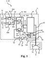
- the hearing device 2, 2A comprises a first housing 4 configured as a behind-the-ear housing to be worn behind the pinna of a user; a second housing 6 configured as an earpiece housing to be worn in or at the ear canal of a user; and a wire 8 connecting the first housing 4 and the second housing 6.
- the hearing device 2, 2A comprises a primary set of microphones 10, 12 arranged in the first housing 4, the primary set of microphones including a primary first microphone 10 for provision of a primary first microphone input signal 10A, and a primary second microphone 12 for provision of a primary second microphone input signal 12A.
- the hearing device 2, 2A comprises a secondary microphone 14 arranged in the second housing 6 for provision of a secondary microphone input signal 14A.
- the hearing device 2, 2A comprises a mixing module 16 for provision of a mixer output 18 based on a primary mixer input 20 and a secondary mixer input 22, wherein the primary mixer input 20 is optionally based on the primary first microphone input signal 10A and/or the primary second microphone input signal 12A, and the secondary mixer input 22 is based on the secondary microphone input signal 14A.
- the hearing device 2, 2A comprises a processor 24 for processing the mixer output 18 and providing an electrical output signal 26 based on mixer output 18; and a receiver 28 for converting the electrical output signal 26 to an audio output signal.
- the mixing module 16 comprises a primary mixing filter 30 and a secondary mixing filter 32 for filtering broadband primary mixer input 20 and broadband secondary mixer input 22, respectively, in the time-domain. Filtered primary mixer input 33A and filtered secondary mixer input 33B are fed to adder 34 of the mixing module 16 for forming the mixer output 18. Accordingly, the mixing module 16 is configured to mix a broadband primary first component of the primary mixer input 20 and a secondary first component of the secondary mixer input 22 for provision of a broadband first component of the mixer output 18.
- the mixing module 16A comprises a primary gain unit 30A and a secondary gain unit 32A for applying respective gains or coefficients of first linear combination to broadband primary mixer input 20 and broadband secondary mixer input 22, respectively, in the time-domain.
- the outputs from gain units 30A and 32A are fed to adder 34 of the mixing module 16 for forming the mixer output 18.
- the mixing module 16A is configured to mix a broadband primary first component of the primary mixer input 20 and a secondary first component of the secondary mixer input 22 for provision of a broadband first component of the mixer output 18 by applying a first linear combination to broadband primary first component as primary mixer input 20 and broadband secondary first component as secondary mixer input 22 for provision of broadband first component as mixer output 18.
- the primary gain unit 30A applies a primary coefficient a_1 as a primary gain to the primary mixer input 20 and the secondary gain unit 32A applies a secondary coefficient b_1 as a secondary gain to the secondary mixer input 22.
- the primary coefficient may be in the range from 0.1 to 0.9 and/or the secondary coefficient may be in the range from 0.1 to 0.9.
- the hearing device 2, 2A may comprise a primary pre-processor 36 for forming the primary mixer input 20 based on the primary first microphone input signal 10A and/or the primary second microphone input signal 12A.
- a first filter 36A optionally filters primary first microphone input signal 10A and a second filter 36B optionally filters the primary second microphone input signal 12A.
- the (optionally filtered) primary first microphone input signal 10A and the (optionally filtered) primary second microphone input signal 12A are fed to adder 36C for forming the primary mixer input 20 as the sum of (optionally filtered) primary first microphone input signal 10A and (optionally filtered) primary second microphone input signal 12A.
- the first filter 36A and the second filter 36B may be pinna-restoration filters.
- the hearing device 2 and/or the hearing device, 2A may comprise a secondary pre-processor 38 for forming the secondary mixer input 22 based on the secondary microphone input signal 14A.
- the secondary microphone input signal 14A may be fed to the respective mixing module 16, 16A as the secondary mixer input.
- a filter and/or a delay 36A optionally filters and/or delays secondary microphone input signal 14A for provision of secondary mixer input 22, e.g. for the secondary mixer input 22 to match the primary mixer input 20.
- the hearing device 2 and/or the hearing device 2A comprises a mixing controller 44 configured to determine presence of a switch or sound event e.g. with switch detector 45; in accordance with a determination that a sound event is present, increase an amount of the secondary mixer input in the mixer output for a time period, e.g. by increasing amplitude of filter transfer function of secondary mixing filter 32 or increasing gains/coefficients of secondary gain unit 32A; and reduce the amount of the secondary mixer input in the mixer output after the time period, e.g. by reducing amplitude of filter transfer function of secondary mixing filter 32 or reducing gains/coefficients of secondary gain unit 32A.
- the mixing controller sends a control signal 52 with control parameter(s) to control the mixing module 16, 16A, e.g. for controlling filter coefficients or gains in the mixing module.
- the time period may be adaptive and/or be in the range from 2 ms to 20 ms, such as in the range 5 ms to 15 ms.
- the mixing controller 44 may be configured to determine the control parameter(s), e.g. based on one or more operating parameters of the hearing device, e.g. from processor 24 as indicated by dashed conductor 46 and/or one or both of electrical output signal 26 and secondary microphone input signal 14A as indicated by respective dashed conductors 48, 50.
- the primary first microphone input signal 10A and/or primary second microphone input signal 12A (or filtered versions thereof) is fed to the mixing controller 44 for determining presence of a switch event/sound event based on the primary first microphone input signal 10A and/or primary second microphone input signal 12A.
- Primary mixer input 20 and/or secondary mixer input 22 may be fed to the mixing controller 44 for optionally determining presence of a switch event/sound event based on one or both of these inputs 20, 22.
- the mixing controller 44 may be configured to determine the presence of a sound event is based on one or more of the primary first microphone input signal 10A, the primary second microphone input signal 12A, and the secondary microphone input signal 14A.
- the mixing controller 44 controls the mixing module 16, 16A, e.g. by setting filter coefficient(s) or coefficients of mixing filters 30, 32 or gain units 30A, 32A, respectively with control signal 52.
- the mixing controller 44 may be configured to determine the time period based on one or more operating parameters, such as program identifier, gain(s), feedback parameter(s), of the hearing device optionally received from processor 24 via conductor 46.
- the mixing controller 44 may be configured to increase an amount of the secondary mixer input in the mixer output and determine if a switching criterion is satisfied, i.e. to increase an amount of the secondary mixer input in the mixer output for a time period optionally comprises to increase an amount of the secondary mixer input in the mixer output and determine if a switching criterion is satisfied.
- the switching criterion evaluated in the mixing controller 44 may be based on one or more gains, such as a closed-loop gain, and/or feedback parameters of the hearing device. In other words, the hearing device may use an increased amount of secondary mixer input in the mixer output until the mixing controller determines that instability is either present or imminent.
- the switching criterion may be satisfied if a feedback parameter indicative of the risk of feedback reaches a threshold.
- the switching criterion may be satisfied if a closed-loop gain reaches a threshold.
- to reduce the amount of the secondary mixer input in the mixer output after the time period comprises to reduce the amount of the secondary mixer input in the mixer output in accordance with the mixing controller 44 determining that the switching criterion is satisfied.
- the mixing controller 44 may be configured to reduce the amount of the secondary mixer input in the mixer output in accordance with a determination that the switching criterion is satisfied.
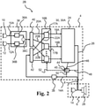
- Fig. 2 shows a hearing device with multi-band mixing module.
- the hearing device 2B comprises a primary filter-bank 40 for provision of a multi-band primary mixer input comprising N components of the primary mixer input including primary first component 20A and primary second component 20B of primary mixer input based on microphone input signals 10A and 12A.
- the hearing device 2B comprises a secondary filter-bank 42 for provision of a multi-band secondary mixer input comprising N components of the secondary mixer input (N may be larger than 5 or larger than 15) including secondary first component 22A and secondary second component 22B of secondary mixer input based on microphone input signal 14A.
- the mixing module 16B comprises a first linear combiner 17A configured to mix primary first component 20A and secondary first component 22A by applying a first linear combination defined by primary coefficient a_1 and secondary coefficient b_1 to respective components 20A, 22A for provision of a first component 18A of the mixer output.
- the mixing module 16B comprises a second linear combiner 17B configured to mix primary second component 20B and secondary second component 22B by applying a second linear combination defined by primary coefficient a_2 and secondary coefficient b_2 to respective components 20B, 22B for provision of a second component 18B of the mixer output.
- the mixing module 16B may comprise N linear combiners including N'th linear combiner 17C configured to mix respective N primary and secondary components for provision of N components of the mixer output.
- the second linear combination is different from the first linear combination.
- the hearing device 2B optionally comprises a mixing controller 44 as described in relation to Fig. 1 , e.g. configured to apply a mixing scheme in the mixing module 16B.
- the mixing controller 44 controls the mixing module 16B, e.g. by setting linear combinations/coefficients of linear combiners 17A, 17B, ..., 17C with control signal 52, e.g. according to determination of a switch event/sound event.
- the mixing controller 44 optionally increases and/or reduces the amount of the secondary mixer input in the mixer output by setting linear combinations/coefficients of linear combiners 17A, 17B, ..., 17C with control signal 52.
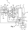
- Fig. 3 shows a hearing device with multi-band primary pre-processor 37 and multi-band mixing module 16B.
- the hearing device 2C comprises a primary first filter-bank 40A for provision of a multi-band primary first microphone input signal comprising N components that are fed to multiband pre-processor 37.
- the hearing device 2C comprises a primary second filter-bank 40B for provision of a multi-band primary second microphone input signal comprising N components that are fed to multiband pre-processor 37.
- the first filter 36A, the second filter 36B and adder 36C of pre-processor 37 are multi-band implementations for provision of multi-band primary mixer input.
- multi-band pinna restoration and multiband mixing is provided, which in turn may increase the user experience by improving directional or spatial cues with reduced howling and/or feedback.
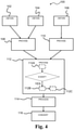
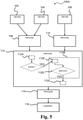
- Fig. 4 is a flow diagram of an exemplary method of operating a hearing device, the hearing device comprising a first housing configured as a behind-the-ear housing to be worn behind the pinna of a user; a second housing configured as an earpiece housing to be worn in or at the ear canal of a user; a wire connecting the first housing and the second housing; a primary set of microphones arranged in the first housing, the primary set of microphones including a primary first microphone and a primary second microphone; a secondary microphone arranged in the second housing; a mixing module; a mixing controller; a processor; and a receiver, the method 100 comprising obtaining 102 a primary first microphone input signal with the primary first microphone; obtaining 104 a primary second microphone input signal with the primary second microphone; obtaining 106 a secondary microphone input signal with the secondary microphone; providing 108 a primary mixer input based on the primary first microphone input signal and/or the primary second microphone input signal; providing 110 a secondary mixer input based on the secondary microphone input signal; providing 112
- providing 112 a mixer output based on the primary mixer input and the secondary mixer input comprises determining 112 presence of a sound event or a switch event; in accordance with determining presence of a sound event, increasing 112B an amount of the secondary mixer input in the mixer output for a time period; and reducing 112C the amount of the secondary mixer input in the mixer output after the time period.
- Increasing 112B an amount of the secondary mixer input in the mixer output for a time period optionally comprises reducing an amount of the primary mixer input in the mixer output for a time period.
- Reducing 112C the amount of the secondary mixer input in the mixer output after the time period optionally comprises increasing the amount of the primary mixer input in the mixer output after the time period.
- Fig. 5 is a flow diagram of an exemplary method 100A of operating a hearing device.
- the method 100A comprises providing 113 a mixer providing a mixer output based on the primary mixer input and the secondary mixer input including increasing 112B an amount of the secondary mixer input in accordance with determining presence of a sound event.
- increasing 112B an amount of the secondary mixer input in the mixer output for a time period comprises increasing 112E an amount of the secondary mixer input in the mixer output and determine 112D if a switching criterion is satisfied, and wherein reducing 112C the amount of the secondary mixer input in the mixer output after the time period comprises reducing 112C the amount of the secondary mixer input in the mixer output in accordance with a determination that the switching criterion is satisfied.
- Fig. 6 shows an example of 4 seconds of speech (3 speakers in a reverberant room).
- the red lines 54 indicate instants of sound events in the speech, i.e. the mixing controller determines presence of a sound event at time instants indicated by the red lines and increases an amount of the secondary mixer input in the mixer output for a time period, e.g. by switching to only use the secondary mixer input in the mixer output or increasing one or more of the coefficients/gains applied to the secondary mixer input in the mixing module.
- Figs. 1-6 comprise some modules or operations which are illustrated with a solid line and some modules or operations which are illustrated with a dashed line.
- the modules or operations which are comprised in a solid line are modules or operations which are comprised in the broadest example embodiment.
- the modules or operations which are comprised in a dashed line are example embodiments which may be comprised in, or a part of, or are further modules or operations which may be taken in addition to the modules or operations of the solid line example embodiments. It should be appreciated that these operations need not be performed in order presented. Furthermore, it should be appreciated that not all of the operations need to be performed.
- the exemplary operations may be performed in any order and in any combination.
- a computer-readable medium may include removable and non-removable storage devices including, but not limited to, Read Only Memory (ROM), Random Access Memory (RAM), compact discs (CDs), digital versatile discs (DVD), etc.
- program modules may include routines, programs, objects, components, data structures, etc. that perform specified tasks or implement specific abstract data types.
- Computer-executable instructions, associated data structures, and program modules represent examples of program code for executing steps of the methods disclosed herein. The particular sequence of such executable instructions or associated data structures represents examples of corresponding acts for implementing the functions described in such steps or processes.
Landscapes
- Engineering & Computer Science (AREA)
- Health & Medical Sciences (AREA)
- General Health & Medical Sciences (AREA)
- Otolaryngology (AREA)
- Physics & Mathematics (AREA)
- Acoustics & Sound (AREA)
- Signal Processing (AREA)
- Neurosurgery (AREA)
- Manufacturing & Machinery (AREA)
- Stereophonic System (AREA)
- Circuit For Audible Band Transducer (AREA)
- Amplifiers (AREA)
Applications Claiming Priority (1)
| Application Number | Priority Date | Filing Date | Title |
|---|---|---|---|
| DKPA202070531A DK181039B1 (en) | 2020-08-14 | 2020-08-14 | Hearing device with microphone switching and related method |
Publications (1)
| Publication Number | Publication Date |
|---|---|
| EP3955593A1 true EP3955593A1 (de) | 2022-02-16 |
Family
ID=76920546
Family Applications (1)
| Application Number | Title | Priority Date | Filing Date |
|---|---|---|---|
| EP21185272.8A Pending EP3955593A1 (de) | 2020-08-14 | 2021-07-13 | Hörgerät mit mikrofonschaltung und entsprechendes verfahren |
Country Status (5)
| Country | Link |
|---|---|
| US (1) | US11653147B2 (de) |
| EP (1) | EP3955593A1 (de) |
| JP (1) | JP2022032995A (de) |
| CN (1) | CN114079849A (de) |
| DK (1) | DK181039B1 (de) |
Citations (4)
| Publication number | Priority date | Publication date | Assignee | Title |
|---|---|---|---|---|
| EP2806660A1 (de) * | 2013-05-22 | 2014-11-26 | GN Resound A/S | Hörgerät mit verbesserter Ortung |
| EP2849462A1 (de) * | 2013-09-17 | 2015-03-18 | Oticon A/s | Hörgerätevorrichtung mit einem Eingangswandlersystem |
| WO2016063220A1 (en) * | 2014-10-24 | 2016-04-28 | Cochlear Limited | Sound processing in a hearing device using externally and internally received sounds |
| EP3481085A1 (de) * | 2017-11-01 | 2019-05-08 | Oticon A/s | Rückkopplungsdetektor und hörgerät mit einem rückkopplungsdetektor |
Family Cites Families (9)
| Publication number | Priority date | Publication date | Assignee | Title |
|---|---|---|---|---|
| US8107654B2 (en) * | 2008-05-21 | 2012-01-31 | Starkey Laboratories, Inc | Mixing of in-the-ear microphone and outside-the-ear microphone signals to enhance spatial perception |
| US8804984B2 (en) * | 2011-04-18 | 2014-08-12 | Microsoft Corporation | Spectral shaping for audio mixing |
| US9432778B2 (en) * | 2014-04-04 | 2016-08-30 | Gn Resound A/S | Hearing aid with improved localization of a monaural signal source |
| EP3185588A1 (de) | 2015-12-22 | 2017-06-28 | Oticon A/s | Hörgerät mit einem rückkopplungsdetektor |
| JP6763721B2 (ja) * | 2016-08-05 | 2020-09-30 | 大学共同利用機関法人情報・システム研究機構 | 音源分離装置 |
| US10284969B2 (en) | 2017-02-09 | 2019-05-07 | Starkey Laboratories, Inc. | Hearing device incorporating dynamic microphone attenuation during streaming |
| US11581864B2 (en) * | 2019-03-15 | 2023-02-14 | Elliptic Laboratories As | Touchless interaction using audio components |
| EP3796677A1 (de) * | 2019-09-19 | 2021-03-24 | Oticon A/s | Verfahren zum adaptiven mischen von unkorrelierten oder korrelierten verrauschten signalen und eine hörvorrichtung |
| DE102020207579A1 (de) * | 2020-06-18 | 2021-12-23 | Sivantos Pte. Ltd. | Verfahren zur richtungsabhängigen Rauschunterdrückung für ein Hörsystem, welches eine Hörvorrichtung umfasst |
-
2020
- 2020-08-14 DK DKPA202070531A patent/DK181039B1/en active IP Right Grant
-
2021
- 2021-07-13 EP EP21185272.8A patent/EP3955593A1/de active Pending
- 2021-07-15 US US17/377,336 patent/US11653147B2/en active Active
- 2021-08-03 JP JP2021127607A patent/JP2022032995A/ja active Pending
- 2021-08-13 CN CN202110928582.XA patent/CN114079849A/zh active Pending
Patent Citations (4)
| Publication number | Priority date | Publication date | Assignee | Title |
|---|---|---|---|---|
| EP2806660A1 (de) * | 2013-05-22 | 2014-11-26 | GN Resound A/S | Hörgerät mit verbesserter Ortung |
| EP2849462A1 (de) * | 2013-09-17 | 2015-03-18 | Oticon A/s | Hörgerätevorrichtung mit einem Eingangswandlersystem |
| WO2016063220A1 (en) * | 2014-10-24 | 2016-04-28 | Cochlear Limited | Sound processing in a hearing device using externally and internally received sounds |
| EP3481085A1 (de) * | 2017-11-01 | 2019-05-08 | Oticon A/s | Rückkopplungsdetektor und hörgerät mit einem rückkopplungsdetektor |
Also Published As
| Publication number | Publication date |
|---|---|
| JP2022032995A (ja) | 2022-02-25 |
| CN114079849A (zh) | 2022-02-22 |
| US11653147B2 (en) | 2023-05-16 |
| DK181039B1 (en) | 2022-10-11 |
| US20210345042A1 (en) | 2021-11-04 |
| DK202070531A1 (en) | 2022-02-25 |
Similar Documents
| Publication | Publication Date | Title |
|---|---|---|
| US10575104B2 (en) | Binaural hearing device system with a binaural impulse environment detector | |
| EP3588985B1 (de) | Binaurales hörvorrichtungssystem mit binauraler aktiver okklusionsunterdrückung | |
| US20100002886A1 (en) | Hearing system and method implementing binaural noise reduction preserving interaural transfer functions | |
| EP2696602B1 (de) | Binaural koordiniertes Kompressionssystem | |
| CN105392096B (zh) | 双耳听力系统及方法 | |
| CN107708045B (zh) | 用于改善听力系统中的接收信号的方法 | |
| CN109121055B (zh) | 抑制梳状滤波效应的听力设备 | |
| JP2019103135A (ja) | 高度な誘導を使用した聴覚機器および方法 | |
| CN111356069B (zh) | 带有自身语音检测的听力装置及相关方法 | |
| EP1827058A1 (de) | Hörgerät mit gleichmäßigem Übergang zwischen Betriebsmodus einer Hörhilfe | |
| US9301058B2 (en) | Method for selecting a preferred direction of a directional microphone and corresponding hearing device | |
| US20230345174A1 (en) | Hearing device with in-ear microphone and related method | |
| EP2928213A1 (de) | Hörgerät mit verbesserter Lokalisierung einer monauralen Signalquelle | |
| EP4311264A2 (de) | Hörgerät mit schallimpulsunterdrückung und zugehöriges verfahren | |
| EP3955593A1 (de) | Hörgerät mit mikrofonschaltung und entsprechendes verfahren | |
| EP4187927A1 (de) | Hörgerät mit adaptiver pinna-wiederherstellung | |
| US12041417B2 (en) | Hearing device with own-voice detection | |
| EP2683179B1 (de) | Hörgerät mit Frequenzdemaskierung | |
| EP3496424B1 (de) | Hörgerät und verfahren mit flexibler steuerung der strahlformung |
Legal Events
| Date | Code | Title | Description |
|---|---|---|---|
| PUAI | Public reference made under article 153(3) epc to a published international application that has entered the european phase |
Free format text: ORIGINAL CODE: 0009012 |
|
| STAA | Information on the status of an ep patent application or granted ep patent |
Free format text: STATUS: THE APPLICATION HAS BEEN PUBLISHED |
|
| AK | Designated contracting states |
Kind code of ref document: A1 Designated state(s): AL AT BE BG CH CY CZ DE DK EE ES FI FR GB GR HR HU IE IS IT LI LT LU LV MC MK MT NL NO PL PT RO RS SE SI SK SM TR |
|
| STAA | Information on the status of an ep patent application or granted ep patent |
Free format text: STATUS: REQUEST FOR EXAMINATION WAS MADE |
|
| 17P | Request for examination filed |
Effective date: 20220810 |
|
| RBV | Designated contracting states (corrected) |
Designated state(s): AL AT BE BG CH CY CZ DE DK EE ES FI FR GB GR HR HU IE IS IT LI LT LU LV MC MK MT NL NO PL PT RO RS SE SI SK SM TR |
|
| STAA | Information on the status of an ep patent application or granted ep patent |
Free format text: STATUS: EXAMINATION IS IN PROGRESS |
|
| 17Q | First examination report despatched |
Effective date: 20240221 |