EP3955558B1 - Device control system and device control method - Google Patents
Device control system and device control method Download PDFInfo
- Publication number
- EP3955558B1 EP3955558B1 EP20818475.4A EP20818475A EP3955558B1 EP 3955558 B1 EP3955558 B1 EP 3955558B1 EP 20818475 A EP20818475 A EP 20818475A EP 3955558 B1 EP3955558 B1 EP 3955558B1
- Authority
- EP
- European Patent Office
- Prior art keywords
- program
- execution
- execution mode
- management apparatus
- user
- Prior art date
- Legal status (The legal status is an assumption and is not a legal conclusion. Google has not performed a legal analysis and makes no representation as to the accuracy of the status listed.)
- Active
Links
- 238000000034 method Methods 0.000 title claims description 34
- 238000012545 processing Methods 0.000 claims description 49
- 230000004044 response Effects 0.000 claims description 29
- 230000015654 memory Effects 0.000 claims description 19
- 230000004048 modification Effects 0.000 description 38
- 238000012986 modification Methods 0.000 description 38
- 230000008569 process Effects 0.000 description 13
- 238000004378 air conditioning Methods 0.000 description 7
- 238000004891 communication Methods 0.000 description 7
- OCKGFTQIICXDQW-ZEQRLZLVSA-N 5-[(1r)-1-hydroxy-2-[4-[(2r)-2-hydroxy-2-(4-methyl-1-oxo-3h-2-benzofuran-5-yl)ethyl]piperazin-1-yl]ethyl]-4-methyl-3h-2-benzofuran-1-one Chemical compound C1=C2C(=O)OCC2=C(C)C([C@@H](O)CN2CCN(CC2)C[C@H](O)C2=CC=C3C(=O)OCC3=C2C)=C1 OCKGFTQIICXDQW-ZEQRLZLVSA-N 0.000 description 3
- 238000010586 diagram Methods 0.000 description 2
- 230000006870 function Effects 0.000 description 2
- 230000006872 improvement Effects 0.000 description 2
- 230000002776 aggregation Effects 0.000 description 1
- 238000004220 aggregation Methods 0.000 description 1
- 238000013459 approach Methods 0.000 description 1
- 230000005540 biological transmission Effects 0.000 description 1
- 238000004364 calculation method Methods 0.000 description 1
- 230000008859 change Effects 0.000 description 1
- 230000001419 dependent effect Effects 0.000 description 1
- 230000000694 effects Effects 0.000 description 1
- 238000005286 illumination Methods 0.000 description 1
- 238000012423 maintenance Methods 0.000 description 1
- 238000004904 shortening Methods 0.000 description 1
- 238000009423 ventilation Methods 0.000 description 1
Images


Classifications
-
- G—PHYSICS
- G06—COMPUTING; CALCULATING OR COUNTING
- G06F—ELECTRIC DIGITAL DATA PROCESSING
- G06F11/00—Error detection; Error correction; Monitoring
- G06F11/30—Monitoring
- G06F11/3003—Monitoring arrangements specially adapted to the computing system or computing system component being monitored
- G06F11/3024—Monitoring arrangements specially adapted to the computing system or computing system component being monitored where the computing system component is a central processing unit [CPU]
-
- G—PHYSICS
- G08—SIGNALLING
- G08C—TRANSMISSION SYSTEMS FOR MEASURED VALUES, CONTROL OR SIMILAR SIGNALS
- G08C17/00—Arrangements for transmitting signals characterised by the use of a wireless electrical link
- G08C17/02—Arrangements for transmitting signals characterised by the use of a wireless electrical link using a radio link
-
- H—ELECTRICITY
- H04—ELECTRIC COMMUNICATION TECHNIQUE
- H04L—TRANSMISSION OF DIGITAL INFORMATION, e.g. TELEGRAPHIC COMMUNICATION
- H04L67/00—Network arrangements or protocols for supporting network services or applications
- H04L67/01—Protocols
- H04L67/12—Protocols specially adapted for proprietary or special-purpose networking environments, e.g. medical networks, sensor networks, networks in vehicles or remote metering networks
- H04L67/125—Protocols specially adapted for proprietary or special-purpose networking environments, e.g. medical networks, sensor networks, networks in vehicles or remote metering networks involving control of end-device applications over a network
-
- G—PHYSICS
- G06—COMPUTING; CALCULATING OR COUNTING
- G06F—ELECTRIC DIGITAL DATA PROCESSING
- G06F11/00—Error detection; Error correction; Monitoring
- G06F11/30—Monitoring
- G06F11/3003—Monitoring arrangements specially adapted to the computing system or computing system component being monitored
- G06F11/3006—Monitoring arrangements specially adapted to the computing system or computing system component being monitored where the computing system is distributed, e.g. networked systems, clusters, multiprocessor systems
-
- G—PHYSICS
- G06—COMPUTING; CALCULATING OR COUNTING
- G06F—ELECTRIC DIGITAL DATA PROCESSING
- G06F11/00—Error detection; Error correction; Monitoring
- G06F11/30—Monitoring
- G06F11/3003—Monitoring arrangements specially adapted to the computing system or computing system component being monitored
- G06F11/3037—Monitoring arrangements specially adapted to the computing system or computing system component being monitored where the computing system component is a memory, e.g. virtual memory, cache
-
- G—PHYSICS
- G06—COMPUTING; CALCULATING OR COUNTING
- G06F—ELECTRIC DIGITAL DATA PROCESSING
- G06F11/00—Error detection; Error correction; Monitoring
- G06F11/30—Monitoring
- G06F11/3065—Monitoring arrangements determined by the means or processing involved in reporting the monitored data
- G06F11/3072—Monitoring arrangements determined by the means or processing involved in reporting the monitored data where the reporting involves data filtering, e.g. pattern matching, time or event triggered, adaptive or policy-based reporting
- G06F11/3075—Monitoring arrangements determined by the means or processing involved in reporting the monitored data where the reporting involves data filtering, e.g. pattern matching, time or event triggered, adaptive or policy-based reporting the data filtering being achieved in order to maintain consistency among the monitored data, e.g. ensuring that the monitored data belong to the same timeframe, to the same system or component
-
- G—PHYSICS
- G06—COMPUTING; CALCULATING OR COUNTING
- G06F—ELECTRIC DIGITAL DATA PROCESSING
- G06F11/00—Error detection; Error correction; Monitoring
- G06F11/30—Monitoring
- G06F11/32—Monitoring with visual or acoustical indication of the functioning of the machine
- G06F11/324—Display of status information
- G06F11/328—Computer systems status display
-
- G—PHYSICS
- G16—INFORMATION AND COMMUNICATION TECHNOLOGY [ICT] SPECIALLY ADAPTED FOR SPECIFIC APPLICATION FIELDS
- G16Y—INFORMATION AND COMMUNICATION TECHNOLOGY SPECIALLY ADAPTED FOR THE INTERNET OF THINGS [IoT]
- G16Y40/00—IoT characterised by the purpose of the information processing
- G16Y40/30—Control
Definitions
- the present disclosure relates to a system for remotely controlling a device and a method for remotely controlling a device.
- PTL 1 Japanese Unexamined Patent Application Publication No. 2009-110300 ) provides a network control apparatus capable of easily performing a control setting without performing a control setting of a device for individual manufacturers.
- US 2019/041830 A1 discloses a device control system for remotely controlling a device, comprising: the device; and a management apparatus connected to the device via a network, wherein the management apparatus is capable of executing, in a plurality of execution modes having different processing performances, a program for controlling the device, and the management apparatus is configured to accept input of the program, execute the accepted program in a first execution mode which is one of the plurality of execution modes, determine, based on an execution result, an execution mode in which the program is to be executed, and execute the accepted program in the determined execution mode to control the device.
- JP 2019 008736 A discloses an aggregator server configured to: receive an acquisition request for a piece of information using a service provided to a user and a service request containing a piece of processing content with respect to the information acquired based on the acquisition request to acquire the information requested by the acquisition request using aggregation service; generate an execution environment for providing the service and an execution environment for separating the service; execute a series of processing according to the processing content on the acquired information using the execution environment, and provide the processing result to a request source of the service.
- JP 2008 107944 A discloses an OS (operating system) and a control device.
- the OS is configured to: specify a corresponding event identifier for identifying a certain event when the certain event is carried out; refer to a table to select corresponding set operation frequency as set operation frequency corresponding to the corresponding event identifier; and refer to another table to select and notify corresponding operation frequency coinciding with the corresponding set operation frequency, and corresponding operation voltage corresponding to the corresponding operation frequency.
- the control device is configured to control a CPU to be operated at the corresponding operation frequency and corresponding operation voltage.
- the OS is further configured to: assign a plurality of corresponding processes corresponding to the certain event, to the CPU; compute computed set operation frequency for reducing the power consumption of the CPU based on a processing time when the CPU processes a plurality of corresponding processes; and store in the table the computed set operation frequency as set operation frequency in association with the corresponding event identifier.
- a device control system as a first reference example remotely controls one or more devices.
- the device control system includes the one or more devices and a management apparatus.
- the management apparatus is connected to the one or more devices via a network.
- the management apparatus is capable of executing, in a plurality of execution modes having different processing performances, a program for controlling the one or more devices.
- the management apparatus accepts input of the program, and executes the accepted program in a first execution mode.
- the first execution mode is one of the plurality of execution modes.
- the management apparatus determines, on the basis of an execution result, an execution mode in which the program is to be executed.
- the device control system as the first reference example determines an execution mode on the basis of a result of executing the program for controlling the one or more devices in the first execution mode, and is thus capable of executing the program for controlling the one or more devices in an appropriate execution mode.
- a device control system as a second reference example is the system according to the first reference example, in which the management apparatus includes a CPU and a storage unit.
- the management apparatus registers the accepted program and the determined execution mode in the storage unit.
- the management apparatus executes the program registered in the storage unit in the registered execution mode to control the one or more devices.
- the management apparatus registers not the execution mode used at the execution but the execution mode determined through the execution in the storage unit.
- the management apparatus executes the program in the registered execution mode.
- a device control system as a third reference example is the system according to the first reference example or the second reference example, in which the management apparatus accepts input of an execution condition of the program when accepting the input of the program.
- the management apparatus decides to execute the program in a second execution mode when determining that the execution result of the program does not satisfy the execution condition.
- the second execution mode has a higher processing performance than the first execution mode.
- an execution result is determined on the basis of an execution condition of the program input in advance, and thus the execution condition of the program can be determined more appropriately.
- a device control system as a fourth reference example is the system according to any one of the first reference example to the third reference example, in which an execution time of the program is a sum of a processing time of the management apparatus and a response time of the one or more devices connected via the network.
- a device control system as a fifth reference example is the system according to any one of the first reference example to the fourth reference example, in which the system presents to a user, after the execution in the first execution mode, the execution mode of the program, and cost or/and control quality information.
- the execution mode of the program is an execution mode determined by the management apparatus after the execution in the first execution mode.
- the cost is the cost when the program is executed in the determined execution mode.
- a device control system as a sixth reference example is the system according to the fifth reference example, in which the control quality information includes an execution time of the program.
- a device control system as a seventh reference example is the system according to any one of the first reference example to the sixth reference example, in which an execution time of the execution of the program in the first execution mode is a sum of a processing time of the management apparatus and a response time of the one or more devices connected via the network.
- the system gives a warning to a user if the response time of the one or more devices exceeds a predetermined value.
- a device control system as an eighth reference example is the system according to the second reference example, in which the CPU includes a core and a memory.
- the processing performance of each of the plurality of execution modes includes an operating frequency of the CPU, the number of cores of the CPU, and the number of memories of the CPU.
- a device control system as a ninth reference example is the system according to any one of the first reference example to the eighth reference example, in which the system further includes a control apparatus.
- the control apparatus is connected to the one or more devices.
- the control apparatus is connected to the management apparatus via the network.
- the one or more devices are controlled via the control apparatus.
- a plurality of devices can be connected to the control apparatus.
- communication between the plurality of devices and the management apparatus is centralized, and the management apparatus is capable of collectively control the devices.
- the centralized communication enables communication cost to be reduced.
- a method for controlling a device as a tenth reference example is a method for controlling a device executed by a management apparatus.
- the management apparatus is connected to the device via a network.
- the management apparatus is capable of executing, in a plurality of execution modes having different processing performances, a program for controlling the device.
- the management apparatus accepts input of the program in at least one execution mode of the plurality of execution modes.
- the management apparatus executes the accepted program in the accepted execution mode.
- the management apparatus determines, on the basis of an execution result, one execution mode in which the program is to be executed among the plurality of execution modes.
- the management apparatus executes the accepted program in the determined execution mode to control the device.
- the method for controlling a device as the tenth reference example determines an execution mode on the basis of a result of executing a program for controlling a device in an accepted execution mode, and is thus capable of executing the program for controlling a device in an appropriate execution mode.
- a device control system 1 of the present embodiment includes a device 21, a management apparatus 10, and user terminals 41a and 41b, as illustrated in Fig. 1 .
- the device 21 is installed in a building.
- the device 21 is, for example, an air conditioning apparatus.
- the management apparatus 10 is connected to the device 21 and the user terminals 41a and 41b via a network 15.
- the management apparatus 10 is capable of controlling the device 21 via the network.
- the user terminals 41a and 41b are interfaces between users and the system 1.
- the management apparatus 10 controls the device 21 by remote operation.
- the device 21 is a device installed in a building.
- the building is not limited to the inside of the building, and includes the roof of the building, the surroundings of the building, and the like.
- the building is not limited and may be a commercial building, a residential apartment, a condominium, a public building, a stand-alone house, or the like.
- Examples of the device 21 include an air conditioning apparatus, an illumination device, and a ventilation fan.
- an air conditioning apparatus an outdoor unit and a plurality of indoor units connected to the outdoor unit may be handled as a single device, or the outdoor unit and each indoor unit may be regarded as individual devices.
- the device 21 includes air conditioning apparatuses 21a to 21c for household use.
- the air conditioning apparatus 21a is disposed in a room 25 of an apartment.
- a user is present in the room 25 and carries the user terminal 41a.
- a user includes not only a direct user of the device 21 but also a person who manages facilities of the apartment and a manager who provides a service such as maintenance or energy saving of the device 21. It is assumed that the manager uses the user terminal 41b.
- the device data is data about the each device 21, a sensor disposed inside or outside a room, or the like.
- the device data is transmitted to the management apparatus 10 via the network 15 and is used to control the device 21.
- the user terminals 41a and 41b have a role of a user interface.
- the user terminals 41a and 41b are connected to the management apparatus 10 via the network 15.
- the user terminals 41a and 41b exchange information with the management apparatus 10.
- the user terminals 41a and 41b are computers.
- the user terminals 41a and 41b are personal computer, mobile terminals, or the like.
- the each user terminal 41a and 41b includes a CPU, a memory, an input unit, and a display unit.
- the user terminals 41a and 41b may be dedicated terminals for the management apparatus 10 or may have other functions.
- the user terminals 41a and 41b are general-purpose mobile terminals, especially smartphones.
- a user (a direct user or a manager of the device 21) inputs a control instruction for controlling the device 21 to the user terminal 41a or 41b.
- the control instruction may be input in both the user terminals 41a and 41b, or may be inputtable in only one of them.
- the manager of the device inputs the control instruction for controlling the device 21 to the user terminal 41b.
- the management apparatus 10 includes a CPU 11, a storage unit 12, and other circuits.
- the CPU 11 performs various processes, such as computation, storage or registration in the storage unit, reception or transmission of data or a program, and a trial or execution of a program, in cooperation with the storage unit 12 and the other circuits. In this specification, execution until the management apparatus determines an execution mode may be referred to as a trial.
- the management apparatus 10 may be a virtual apparatus.
- the CPU 11 includes a core and a memory.
- the management apparatus 10 may be provided by a cloud service provider different from a management service provider of the present disclosure.
- the cloud service provider may provide only an infrastructure.
- the infrastructure includes hardware.
- the cloud service provider may provide a platform in addition to the infrastructure.
- the platform includes an operation system.
- the management apparatus 10 is connected to the device 21 and the user terminals 41a and 41b via the network 15.
- a line that connects the management apparatus 10 and the user terminals 41a and 41b may be a private line or may be a public line.
- the private line may be a virtual private network (VPN).
- the line may be provided by the cloud service provider.
- the management apparatus 10 acquires device data from the device 21 or the like.
- the device data is used to control the device as appropriate.
- the management apparatus 10 executes a program for controlling the device 21. Specifically, when the management apparatus executes the device control program, a control instruction for the device 21 is transmitted to the device 21 via the network. A control unit of the device 21 controls individual units of the device 21 on the basis of the received control instruction. For example, when the device 21 is the air conditioning apparatus 21a, the inclination of a flap of the air conditioning apparatus 21a is changed on the basis of a control instruction to change the air direction of an indoor fan.
- the management apparatus 10 provides an environment in which a user creates a program for controlling the device 21. More specifically, the management apparatus 10 provides an application programming interface (API) for registering a script created by the user. The user inputs, in the user terminal 41a or 41b, a script for controlling the device 21.
- API application programming interface
- the management apparatus 10 has a plurality of execution modes having different processing performances for executing a program for controlling the device 21.
- a processing performance includes the operating frequency, the number of cores, the number of memories, and so forth of the CPU 11.
- a first execution mode is implemented with one core and a memory of 512 MB of the CPU
- a second execution mode is implemented with two cores and a memory of 2048 MB of the CPU.
- the management apparatus 10 In response to the user's input of a program (script) for controlling the device 21, the management apparatus 10 accepts the script.
- the management apparatus 10 further registers the script and stores the script in the storage unit 12.
- the management apparatus 10 reads out the registered script from the storage unit 12, selects one execution mode, and executes the program for performing control.
- a user inputs, in the user terminal 41a or 41b, a program for controlling the device 21, a processing performance for a trial, and an execution condition. More specifically, the program is input in the form of a script.
- the processing performance includes the number of cores of the CPU, an operating frequency, and the number of memories of the CPU.
- the processing performance corresponds to one of the execution modes in accordance with the selection of the above.
- the execution condition includes a script maximum execution time and so on.
- the management apparatus 10 accepts the program input by the user (S101).
- the management apparatus 10 temporarily stores, in the memory in the CPU 11, the accepted program, the processing performance (execution mode), and the execution condition (S102).
- the management apparatus 10 selects an execution mode in accordance with the processing performance designated by the user (S103). It is assumed that the execution mode selected in this step is the first execution mode.
- the management apparatus 10 tries (executes) the stored program in the first execution mode (S104).
- the management apparatus 10 monitors an execution state while executing the program.
- the target to be monitored includes an execution time of the program, a CPU usage rate, and a memory usage rate.
- step S105 the management apparatus 10 determines an execution mode on the basis of the execution state of the trial of the program. In other words, the management apparatus 10 determines whether to select the tried first execution mode or to select another execution mode.
- the determination in step S105 is made in accordance with the execution state of the program executed in the first execution mode. For example, the determination is made in accordance with the execution time. If the execution time is shorter than or equal to a predetermined time, the first execution mode is selected. If the execution time is longer than the predetermined time, the second execution mode, which has a higher processing performance than the first execution mode, is selected.
- step S106 the program and the first execution mode are registered and stored in the storage unit 12.
- step S105 If the first execution mode is not selected and it is determined to select another execution mode in step S105, the process proceeds to step S107, where the program and the selected execution mode (for example, the second execution mode) are registered in the storage unit 12.
- the program and the selected execution mode for example, the second execution mode
- step S106 or step S107 the process proceeds to step S108, where the management apparatus 10 calls the program registered in the storage unit 12 and the execution mode of the program, and executes the program in the execution mode to control the device 21.
- the device control system 1 of the first embodiment includes the device 21 and the management apparatus 10 connected to the device 21 via the network.
- the management apparatus 10 includes the CPU 11 and the storage unit 12.
- the management apparatus 10 accepts a program for controlling the device 21 input by a user (S101).
- the management apparatus 10 has a plurality of execution modes for executing the program for controlling the device 21.
- the management apparatus 10 tries the accepted program in one selected execution mode (first execution mode) (S104).
- the management apparatus 10 determines, on the basis of a trial result, whether execution of the program in the first execution mode is appropriate or not (S105). If it is determined that execution in the first execution mode is appropriate, the management apparatus 10 registers the first execution mode together with the program in the storage unit 12 (S106). The management apparatus 10 executes the registered program in the registered execution mode to control the device 21 (S108).
- the management apparatus 10 that performs remote control is capable of controlling a plurality of devices via a network.
- a user may input a program (script) for performing complex control, for example, simultaneously controlling a plurality of devices.
- the device control system 1 of the first embodiment has a plurality of execution modes for a control program and is thus capable of selecting and executing an appropriate execution mode in accordance with the complexity, cost, and so forth of the program.
- Some users of the device control system 1 may be unfamiliar with an execution environment parameter (a processing performance, an execution condition, and so forth) required for executing the program.
- the control program is tried in one execution mode and an appropriate execution mode is determined.
- an appropriate execution mode is determined.
- the management apparatus 10 accepts input of a program together with input of an execution condition of the program (S101).
- the execution condition is, for example, a condition that the execution time of the program is shorter than or equal to a predetermined time.
- a trial of the program is performed (S104).
- the management apparatus 10 decides to execute the program in the second execution mode, which has a higher processing performance than the first execution mode (S105).
- the device control system 1 of the first embodiment accepts input of an execution condition from a user and determines, on the basis of a result of a trial (S104), an execution mode so as to satisfy the execution condition (S105).
- S104 a result of a trial
- S105 an execution mode so as to satisfy the execution condition
- the management apparatus 10 tries a program and then registers a determined execution mode in the storage unit 12.
- the device control system 1 of the first embodiment performs a trial before registering a control program and an execution mode, and is thus capable of registering a more appropriate execution mode.
- a device control system 1a of Modification Example 1A includes a management apparatus 10, a control apparatus 30, a device 21, and a user terminal 42, as illustrated in Fig. 2 .
- the functions of the management apparatus 10, the device 21, and the user terminal 42 are almost the same as in the first embodiment.
- the device control system 1a of Modification Example 1A further includes the control apparatus 30.
- the control apparatus 30 is connected to individual devices 21p to 21r.
- the control apparatus 30 is connected to the management apparatus 10 through a communication line via a network 15.
- the individual devices 21p to 21r are connected to the network 15 and the management apparatus 10 via the control apparatus 30.
- Modification Example 1A when the management apparatus 10 executes a control program for the device 21, a control instruction is transmitted to the control apparatus 30.
- the control apparatus 30 controls the device 21 in accordance with the control instruction.
- a user is a manager of a building, for example.
- the user controls the devices 21p to 21r in the entire building.
- the user terminal 42 may be a personal computer.
- the control apparatus 30 controls the individual devices 21p to 21r.
- a user simultaneously inputs a processing performance (execution mode) and an execution condition when inputting a program.
- the user may input a program (script) and may not input a processing performance (execution mode) or an execution condition.
- Modification Example 1B the user does not input a processing performance (execution mode) in advance.
- the management apparatus 10 selects an execution mode for trying a program on the basis of the program input by the user.
- the configuration of Modification Example 1B is similar to that of the first execution mode.
- a program (script), a processing performance (execution mode), and an execution condition input by a user are accepted by the management apparatus 10 and are temporarily stored in the memory of the CPU (S102). At this time, the program may be registered in the storage unit 12.
- the accepted program is registered in the storage unit 12 in step S102.
- the execution mode is registered in the storage unit 12 in association with the already registered program.
- the management apparatus 10 tries a control program in the first execution mode (S104), and determines the execution mode to be implemented on the basis of a result of the trial (S105).
- the trial may be performed twice, or three times or more.
- the program may be tried not only in the first execution mode but also in another execution mode.
- step S105 it is determined in step S105 whether a trial result satisfies an execution condition input by a user.
- the execution condition is, for example, whether the execution time of the program is shorter than or equal to a predetermined time. If the execution time is shorter than or equal to the predetermined time, it is determined that the execution condition is satisfied and that the program is to be executed in the first execution mode, and the first execution mode is registered in the storage unit 12 (S106). This case is similar to the first embodiment. If the trial in the first execution mode does not satisfy the execution condition in step S105, the same control program is tried again in another execution mode. The case where the execution condition is not satisfied is, for example, a case where a trial of the program in the first execution mode takes more than the predetermined time. In this case, the second execution mode, which has a higher processing performance than the first execution mode, is selected as another execution mode, and a trial is performed.
- a trial may be repeated if necessary to approach a more appropriate execution mode.
- the execution condition is whether the execution time of the program is shorter than or equal to a predetermined time.
- the execution condition is not limited thereto.
- the execution condition is a CPU average usage rate.
- step S105 it is determined whether a trial result is lower than or equal to a CPU average usage rate input by the user.
- the execution condition is CPU average usage rate.
- the execution condition may be a program average execution time, a CPU maximum usage rate, a memory average usage rate, or a memory maximum usage rate.
- Modification Example 1D a description has been given of the case of repeating a trial of a program until an execution condition designated by a user is satisfied.
- An upper limit may be set for the number of trials of a program in advance.
- a user sets an upper limit for the number of trials of a program. For example, in Modification Example 1F, the upper limit is three times. If an execution condition is not satisfied after three trials, the user is notified of the fact.
- a limit is set for the number of trials.
- an upper limit may be set for a trial execution time instead of the number of trials.
- An upper limit may be set for both the number of trials and a trial execution time.
- the management apparatus 10 tries a device control program input by a user in the first execution mode, and the management apparatus 10 determines whether to select the first execution mode.
- the same process as that in the first embodiment is performed until a program is tried in the first execution mode.
- the management apparatus 10 inquires of a user which execution mode is to be used to execute a program after trying the program in the first execution mode, and the user determines which execution mode is to be selected.
- the configuration of the device control system 1 of the second embodiment is the same as that of the device control system 1 of the first embodiment in Fig. 1 .
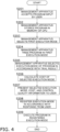
- a method for controlling the device 21 using the device control system 1 of the second embodiment will be described with reference to the flowchart in Fig. 4 .
- the stage up to the trial of a program in steps S201 to S204 is totally the same as steps S101 to S104 of the first embodiment.
- the management apparatus 10 selects an appropriate execution mode on the basis of an execution state at the trial in the first execution mode (S205). Subsequently, the management apparatus 10 calculates the cost of the execution mode (S206).
- the appropriate execution mode may be the first execution mode or may be another execution mode.
- the appropriate execution mode may be one execution mode or may be a plurality of execution modes. In the present embodiment, if the execution state does not have any problems, the first execution mode is selected as an appropriate execution mode. If the management apparatus 10 determines that the execution state has a problem, an execution mode having a higher processing performance is selected as an appropriate execution mode.
- the management apparatus 10 presents the execution mode for which the cost has been calculated, the cost, and control quality information to the user (S207).
- a set of the execution mode, the cost, and the control quality information presented here may be one set, or may be two or more sets.
- the execution mode, the cost, and the control quality information are transmitted to the user terminal 42 and are displayed on a display unit of the user terminal 42.
- the control quality information indicates a margin of processing in the system in a case where the program is executed in the selected execution mode.
- the control quality information includes a processing execution time, a CPU average/maximum usage rate, a memory average/maximum usage rate, and so forth.
- the CPU herein is the CPU 11 of the management apparatus 10, and the memory herein is the memory in the CPU 11.
- the processing execution time includes a processing time of the management apparatus 10 and a response time of the device 21 connected via the network 15. Furthermore, the response time of the device 21 includes a connection response time of the network 15 and a processing time of the device 21.
- the connection response time of the network 15 greatly varies according to a network connection environment.
- the network connection environment includes, for example, a communication scheme such as 5G, LTE, or 3G.
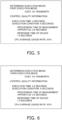
- FIG. 5 A presentation example of control quality information and so forth presented to the user by the management apparatus in step S207 is illustrated in Fig. 5 .
- the determined execution mode, the cost, and the control quality information are displayed. All of them need not necessarily be displayed.
- the determined execution mode and the cost may be displayed, or the determined execution mode and the control quality information may be displayed.
- the first execution mode is displayed as a determined execution mode. This means that the first execution mode is selected in step S205.
- the cost calculated in step S206 is displayed.
- the control quality information obtained through the trial (execution) in step S204 is displayed in the third row and the following rows.
- an execution time of the program, an execution condition (predetermined value) input by the user with respect to the execution time of the program, a processing time of the management apparatus, a response time of the device, and a CPU average usage rate are displayed as the control quality information.
- control quality information presents, to the user, a quantitative degree of an actual value relative to an execution condition even if the execution condition is satisfied, thereby assisting the user in selecting an execution mode.
- a specific example of control quality information further includes the following. It is assumed that a CPU average usage rate as an execution condition in execution of the program is set to 70% or less. It is assumed that an actual value in a trial of the program is 68%. The user can recognize that the execution condition is satisfied but there is a narrow margin. The user is able to make a comprehensive determination on selection of an execution mode in consideration of a result of other parameters.
- the user selects an execution mode on the basis of the presented cost and control quality information.
- the execution mode selected by the user is input to the user terminal 42 and is transmitted to the management apparatus 10 via the network.
- the management apparatus 10 registers a response from the user, in other words, the execution mode selected by the user, in the storage unit 12 (S208).
- the management apparatus 10 executes the program in the registered execution mode to control the device 21 (S209).
- the device control system 1 When inquiring of the user about an execution mode, the device control system 1 presents, to the user, a single execution mode or a plurality of execution modes, the cost thereof, and the control quality information thereof. The user selects an execution mode on the basis of the cost and the control quality information. The management apparatus selects an execution mode in accordance with the selection made by the user.
- the management apparatus 10 presents an execution mode, cost, and control quality information to a user.
- the user is able to select an optimum execution mode in consideration of the cost and the control quality information.
- step S207 a description has been given of a case in which, in step S207, a selected execution mode, cost, and control quality information are always presented to a user.
- the execution mode and so forth may be presented to the user only in a case where a mode other than the first execution mode is selected in step S205.
- an execution state is monitored while a program is being tried in the first execution mode in step S204.
- the management apparatus 10 selects the first execution mode.
- "does not have any problems” means, for example, a case where the execution time of the program is shorter than or equal to a predetermined time.
- step S205 If the management apparatus 10 selects only the first execution mode in step S205, calculation of the cost is not performed in step S206. Presentation of the execution mode and so forth to the user is not performed in step S207. The management apparatus 10 registers the first execution mode in the storage unit 12 instead of performing step S208.
- step S205 if an execution mode other than the first execution mode is selected in step S205, the process proceeds to steps S206 to S208 and the execution mode selected by the user is registered as in the second embodiment.
- Modification Example 2A is similar to that of the second embodiment.
- the management apparatus 10 executes (tries, S204) a control program in the first execution mode, and determines an execution mode to be implemented on the basis of a result of the execution (trial) (S205).
- the execution (trial) may be performed twice, or three times or more.
- the program may be executed (tried) in another execution mode as well as in the first execution mode.
- step S204 it is determined, after step S204, whether a result of the execution (trial) satisfies an execution condition input by a user.
- the execution condition is, for example, whether the execution time of the program is shorter than or equal to a predetermined value. If the execution time is shorter than or equal to the predetermined value, it is determined that the execution condition is satisfied and that the program is to be executed in the first execution mode (S205). This case is similar to the second embodiment. If the execution (trial) in the first execution mode does not satisfy the execution condition, the same control program is executed again in another execution mode. The case where the execution condition is not satisfied is, for example, a case where the execution of the program in the first execution mode exceeds the predetermined value. In this case, the second execution mode, which has a higher processing performance than the first execution mode, is selected and implemented as another execution mode.
- Modification Example 2B if the execution of the control program in the second execution mode does not satisfy the execution condition designated by the user, the program is further executed (tried) in the third execution mode. In this way, execution of the program is repeated until the execution condition designated by the user is satisfied, as long as there is an execution mode having a higher processing performance.
- the number of execution modes is typically limited. Thus, execution as a trial ends after the limited number of executions regardless of whether the execution condition designated by the user is satisfied.
- the management apparatus selects an execution mode of the program through the above-described process (step S205).
- Step S206 and the following steps are the same as in the second embodiment.
- FIG. 6 An example of the execution mode, cost, and control quality information presented to the user in step S207 in Modification Example 2B is illustrated in Fig. 6 .
- Fig. 6 "third execution mode” is displayed as a "determined execution mode", which indicates that the execution condition is satisfied in the third execution (trial). The usage cost and control quality information when the third execution mode is selected are simultaneously presented.
- the device control system 1 of a third embodiment includes a device 21 and a management apparatus 10 connected to the device 21 via a network 15, as in the first and second embodiments.
- Steps S301 to S304 of the third embodiment are the same as steps S201 to S204 of the second embodiment.
- step S305 it is determined in step S305 whether a result of the execution (trial) of a program in the first execution mode in step S304 satisfies an execution condition designated by a user. Specifically, it is determined whether an execution time in the first execution mode satisfies an execution condition of being shorter than a predetermined value.
- the predetermined value of the execution time is a target value which is a desired maximum execution time. The predetermined value may be input by the user together with the program, or the management apparatus 10 may set an appropriate value as the predetermined value.
- Step S306 the first execution mode is selected in step S306, and the process proceeds to steps S307 to S310.
- Steps S306 to S310 of the third embodiment are the same as steps S205 to S209 of the second embodiment.
- step S305 If the execution time is longer than or equal to the predetermined value in step S305, the process proceeds to step S311.
- step S311 it is determined whether, of the execution time during which the program is executed (tried) in the first execution mode, a response time of the device exceeds a predetermined value.
- the predetermined value used in step S311 may be the same as or different from the predetermined value used in step S305.
- step S311 If the response time of the device is shorter than the predetermined value in step S311, it indicates that the total execution time can be reduced below the predetermined value by shortening the response time of the management apparatus. In this case, the management apparatus 10 executes the program in the second execution mode, which has a higher processing performance than the first execution mode (S312). After step S312, the process returns to step S305, and condition determination is repeated.
- step S311 If the response time of the device is longer than or equal to the predetermined value in step S311, a warning and the response time of the device are presented to the user (S313). If the response time of the device is longer than or equal to the predetermined value, the management apparatus may give a warning to the user and also determine an execution mode in which the program is to be executed.
- FIG. 8 An example of a display screen presented to the user in step S313 is illustrated in Fig. 8 .
- the executed (tried) execution mode is the first execution mode.
- the control quality information includes an execution time when the program is executed in the first execution mode, an execution condition (predetermined value) input by the user with respect to the execution time of the program, a processing time of the management apparatus 10, a response time of the device 21, and a CPU average usage rate.
- a warning to the user "the response time of the device needs to be 5 seconds or less" is displayed under the response time of the device.
- either one of the warning and the response time of the device may be displayed.
- the execution time of the program is the sum of the processing time of the management apparatus 10 and the response time of the device 21 connected via the network. If the response time of the device exceeds the predetermined value, it is not possible to sufficiently shorten the execution time even if the management apparatus 10 selects an execution mode having a high processing performance.
- the response time of the device includes a network connection response time and a processing time of the device. If the response time of the device exceeds the predetermined value, the network connection response time is long in many cases.
- the user needs to cope with an improvement of the network (communication environment) separately from an improvement of the management apparatus 10 or the device 21.
- the system 1 gives a warning to the user and prompts the user to improve the communication environment.
Description
- The present disclosure relates to a system for remotely controlling a device and a method for remotely controlling a device.
- There has been known a network control apparatus that controls an information household electric appliance from a server via a network. Regarding such a network control apparatus, PTL 1 (
Japanese Unexamined Patent Application Publication No. 2009-110300 -
US 2019/041830 A1 discloses a device control system for remotely controlling a device, comprising: the device; and a management apparatus connected to the device via a network, wherein the management apparatus is capable of executing, in a plurality of execution modes having different processing performances, a program for controlling the device, and the management apparatus is configured to accept input of the program, execute the accepted program in a first execution mode which is one of the plurality of execution modes, determine, based on an execution result, an execution mode in which the program is to be executed, and execute the accepted program in the determined execution mode to control the device. -
JP 2019 008736 A -
JP 2008 107944 A - When a user inputs a control program to a system for remotely controlling a device, it is difficult for the user to input an execution environment parameter required for executing the program if the user is not familiar with the program.
- The problem above is solved by the device control system defined by the appended
claim 1 and the method for controlling a device defined by claim 9. Further advantageous effects can be obtained by the preferred embodiments defined by appended dependent claims. - A device control system as a first reference example remotely controls one or more devices. The device control system includes the one or more devices and a management apparatus. The management apparatus is connected to the one or more devices via a network. The management apparatus is capable of executing, in a plurality of execution modes having different processing performances, a program for controlling the one or more devices. The management apparatus accepts input of the program, and executes the accepted program in a first execution mode. The first execution mode is one of the plurality of execution modes. The management apparatus determines, on the basis of an execution result, an execution mode in which the program is to be executed.
- The device control system as the first reference example determines an execution mode on the basis of a result of executing the program for controlling the one or more devices in the first execution mode, and is thus capable of executing the program for controlling the one or more devices in an appropriate execution mode.
- A device control system as a second reference example is the system according to the first reference example, in which the management apparatus includes a CPU and a storage unit.
The management apparatus registers the accepted program and the determined execution mode in the storage unit. The management apparatus executes the program registered in the storage unit in the registered execution mode to control the one or more devices. - In the device control system as the second reference example, the management apparatus registers not the execution mode used at the execution but the execution mode determined through the execution in the storage unit. The management apparatus executes the program in the registered execution mode.
- A device control system as a third reference example is the system according to the first reference example or the second reference example, in which the management apparatus accepts input of an execution condition of the program when accepting the input of the program. The management apparatus decides to execute the program in a second execution mode when determining that the execution result of the program does not satisfy the execution condition. The second execution mode has a higher processing performance than the first execution mode.
- In the device control system as the third reference example, an execution result is determined on the basis of an execution condition of the program input in advance, and thus the execution condition of the program can be determined more appropriately.
- A device control system as a fourth reference example is the system according to any one of the first reference example to the third reference example, in which an execution time of the program is a sum of a processing time of the management apparatus and a response time of the one or more devices connected via the network.
- A device control system as a fifth reference example is the system according to any one of the first reference example to the fourth reference example, in which the system presents to a user, after the execution in the first execution mode, the execution mode of the program, and cost or/and control quality information. The execution mode of the program is an execution mode determined by the management apparatus after the execution in the first execution mode. The cost is the cost when the program is executed in the determined execution mode.
- A device control system as a sixth reference example is the system according to the fifth reference example, in which the control quality information includes an execution time of the program.
- A device control system as a seventh reference example is the system according to any one of the first reference example to the sixth reference example, in which an execution time of the execution of the program in the first execution mode is a sum of a processing time of the management apparatus and a response time of the one or more devices connected via the network. The system gives a warning to a user if the response time of the one or more devices exceeds a predetermined value.
- A device control system as an eighth reference example is the system according to the second reference example, in which the CPU includes a core and a memory. The processing performance of each of the plurality of execution modes includes an operating frequency of the CPU, the number of cores of the CPU, and the number of memories of the CPU.
- A device control system as a ninth reference example is the system according to any one of the first reference example to the eighth reference example, in which the system further includes a control apparatus. The control apparatus is connected to the one or more devices. The control apparatus is connected to the management apparatus via the network. The one or more devices are controlled via the control apparatus.
- In the device control system as the ninth reference example, a plurality of devices can be connected to the control apparatus. Thus, communication between the plurality of devices and the management apparatus is centralized, and the management apparatus is capable of collectively control the devices. The centralized communication enables communication cost to be reduced.
- A method for controlling a device as a tenth reference example is a method for controlling a device executed by a management apparatus. The management apparatus is connected to the device via a network. The management apparatus is capable of executing, in a plurality of execution modes having different processing performances, a program for controlling the device. The management apparatus accepts input of the program in at least one execution mode of the plurality of execution modes. The management apparatus executes the accepted program in the accepted execution mode. The management apparatus determines, on the basis of an execution result, one execution mode in which the program is to be executed among the plurality of execution modes. The management apparatus executes the accepted program in the determined execution mode to control the device.
- The method for controlling a device as the tenth reference example determines an execution mode on the basis of a result of executing a program for controlling a device in an accepted execution mode, and is thus capable of executing the program for controlling a device in an appropriate execution mode.
-
-
Fig. 1 is a diagram illustrating an overall configuration of adevice control system 1 of a first embodiment. -
Fig. 2 is a diagram illustrating an overall configuration of adevice control system 1a of Modification Example 1. -
Fig. 3 is a flowchart of a method for controlling a device of the first embodiment. -
Fig. 4 is a flowchart of a method for controlling a device of a second embodiment. -
Fig. 5 illustrates a display example of a screen presented to a user in the method for controlling a device of the second embodiment. -
Fig. 6 illustrates a display example of a screen presented to a user in a method for controlling a device of Modification Example 2B. -
Fig. 7 A is part of a flowchart of a method for controlling a device of a third embodiment. -
Fig. 7B is part of the flowchart of the method for controlling a device of the third embodiment. -
Fig. 8 illustrates a display example of a screen presented to a user in the method for controlling a device of the third embodiment. - A
device control system 1 of the present embodiment includes adevice 21, amanagement apparatus 10, anduser terminals Fig. 1 . Thedevice 21 is installed in a building. Thedevice 21 is, for example, an air conditioning apparatus. Themanagement apparatus 10 is connected to thedevice 21 and theuser terminals network 15. Themanagement apparatus 10 is capable of controlling thedevice 21 via the network. Theuser terminals system 1. - In the
device control system 1 of the present embodiment, themanagement apparatus 10 controls thedevice 21 by remote operation. - The
device 21 is a device installed in a building. The building is not limited to the inside of the building, and includes the roof of the building, the surroundings of the building, and the like. The building is not limited and may be a commercial building, a residential apartment, a condominium, a public building, a stand-alone house, or the like. - Examples of the
device 21 include an air conditioning apparatus, an illumination device, and a ventilation fan. As an air conditioning apparatus, an outdoor unit and a plurality of indoor units connected to the outdoor unit may be handled as a single device, or the outdoor unit and each indoor unit may be regarded as individual devices. - In the present embodiment, it is assumed that the
device 21 includesair conditioning apparatuses 21a to 21c for household use. Theair conditioning apparatus 21a is disposed in aroom 25 of an apartment. A user is present in theroom 25 and carries theuser terminal 41a. Here, a user includes not only a direct user of thedevice 21 but also a person who manages facilities of the apartment and a manager who provides a service such as maintenance or energy saving of thedevice 21. It is assumed that the manager uses theuser terminal 41b. - In association with the
device 21, there are various pieces of device-related information, in other words, device data. The device data is data about the eachdevice 21, a sensor disposed inside or outside a room, or the like. The device data is transmitted to themanagement apparatus 10 via thenetwork 15 and is used to control thedevice 21. - The
user terminals - The
user terminals management apparatus 10 via thenetwork 15. Theuser terminals management apparatus 10. - The
user terminals user terminals user terminal user terminals management apparatus 10 or may have other functions. In the present embodiment, theuser terminals - A user (a direct user or a manager of the device 21) inputs a control instruction for controlling the
device 21 to theuser terminal user terminals device 21 to theuser terminal 41b. - The
management apparatus 10 includes aCPU 11, astorage unit 12, and other circuits. TheCPU 11 performs various processes, such as computation, storage or registration in the storage unit, reception or transmission of data or a program, and a trial or execution of a program, in cooperation with thestorage unit 12 and the other circuits. In this specification, execution until the management apparatus determines an execution mode may be referred to as a trial. Themanagement apparatus 10 may be a virtual apparatus. TheCPU 11 includes a core and a memory. - The
management apparatus 10 may be provided by a cloud service provider different from a management service provider of the present disclosure. The cloud service provider may provide only an infrastructure. The infrastructure includes hardware. The cloud service provider may provide a platform in addition to the infrastructure. The platform includes an operation system. - The
management apparatus 10 is connected to thedevice 21 and theuser terminals network 15. A line that connects themanagement apparatus 10 and theuser terminals - The
management apparatus 10 acquires device data from thedevice 21 or the like. The device data is used to control the device as appropriate. - The
management apparatus 10 executes a program for controlling thedevice 21. Specifically, when the management apparatus executes the device control program, a control instruction for thedevice 21 is transmitted to thedevice 21 via the network. A control unit of thedevice 21 controls individual units of thedevice 21 on the basis of the received control instruction. For example, when thedevice 21 is theair conditioning apparatus 21a, the inclination of a flap of theair conditioning apparatus 21a is changed on the basis of a control instruction to change the air direction of an indoor fan. - The
management apparatus 10 provides an environment in which a user creates a program for controlling thedevice 21. More specifically, themanagement apparatus 10 provides an application programming interface (API) for registering a script created by the user. The user inputs, in theuser terminal device 21. - The
management apparatus 10 has a plurality of execution modes having different processing performances for executing a program for controlling thedevice 21. Here, a processing performance includes the operating frequency, the number of cores, the number of memories, and so forth of theCPU 11. For example, in the case of executing a program in themanagement apparatus 10, a first execution mode is implemented with one core and a memory of 512 MB of the CPU, whereas a second execution mode is implemented with two cores and a memory of 2048 MB of the CPU. - In response to the user's input of a program (script) for controlling the
device 21, themanagement apparatus 10 accepts the script. Themanagement apparatus 10 further registers the script and stores the script in thestorage unit 12. Themanagement apparatus 10 reads out the registered script from thestorage unit 12, selects one execution mode, and executes the program for performing control. - Next, control of the
device 21 by thedevice control system 1 of the present embodiment will be described with reference to the flowchart inFig. 3 . - A user inputs, in the
user terminal device 21, a processing performance for a trial, and an execution condition. More specifically, the program is input in the form of a script. The processing performance includes the number of cores of the CPU, an operating frequency, and the number of memories of the CPU. The processing performance corresponds to one of the execution modes in accordance with the selection of the above. The execution condition includes a script maximum execution time and so on. Themanagement apparatus 10 accepts the program input by the user (S101). Themanagement apparatus 10 temporarily stores, in the memory in theCPU 11, the accepted program, the processing performance (execution mode), and the execution condition (S102). - Subsequently, the
management apparatus 10 selects an execution mode in accordance with the processing performance designated by the user (S103). It is assumed that the execution mode selected in this step is the first execution mode. - Subsequently, the
management apparatus 10 tries (executes) the stored program in the first execution mode (S104). - The
management apparatus 10 monitors an execution state while executing the program. The target to be monitored includes an execution time of the program, a CPU usage rate, and a memory usage rate. - In step S105, the
management apparatus 10 determines an execution mode on the basis of the execution state of the trial of the program. In other words, themanagement apparatus 10 determines whether to select the tried first execution mode or to select another execution mode. - The determination in step S105 is made in accordance with the execution state of the program executed in the first execution mode. For example, the determination is made in accordance with the execution time. If the execution time is shorter than or equal to a predetermined time, the first execution mode is selected. If the execution time is longer than the predetermined time, the second execution mode, which has a higher processing performance than the first execution mode, is selected.
- If the first execution mode is selected, the process proceeds to step S106, where the program and the first execution mode are registered and stored in the
storage unit 12. - If the first execution mode is not selected and it is determined to select another execution mode in step S105, the process proceeds to step S107, where the program and the selected execution mode (for example, the second execution mode) are registered in the
storage unit 12. - After step S106 or step S107, the process proceeds to step S108, where the
management apparatus 10 calls the program registered in thestorage unit 12 and the execution mode of the program, and executes the program in the execution mode to control thedevice 21. - The
device control system 1 of the first embodiment includes thedevice 21 and themanagement apparatus 10 connected to thedevice 21 via the network. Themanagement apparatus 10 includes theCPU 11 and thestorage unit 12. Themanagement apparatus 10 accepts a program for controlling thedevice 21 input by a user (S101). Themanagement apparatus 10 has a plurality of execution modes for executing the program for controlling thedevice 21. - The
management apparatus 10 tries the accepted program in one selected execution mode (first execution mode) (S104). Themanagement apparatus 10 determines, on the basis of a trial result, whether execution of the program in the first execution mode is appropriate or not (S105). If it is determined that execution in the first execution mode is appropriate, themanagement apparatus 10 registers the first execution mode together with the program in the storage unit 12 (S106). Themanagement apparatus 10 executes the registered program in the registered execution mode to control the device 21 (S108). - The
management apparatus 10 that performs remote control is capable of controlling a plurality of devices via a network. Thus, a user may input a program (script) for performing complex control, for example, simultaneously controlling a plurality of devices. Thedevice control system 1 of the first embodiment has a plurality of execution modes for a control program and is thus capable of selecting and executing an appropriate execution mode in accordance with the complexity, cost, and so forth of the program. - Some users of the
device control system 1 may be unfamiliar with an execution environment parameter (a processing performance, an execution condition, and so forth) required for executing the program. In the present embodiment, the control program is tried in one execution mode and an appropriate execution mode is determined. Thus, even if a user designates an inappropriate execution mode, device control can be eventually performed in an appropriate execution mode. - (4-2)
In thedevice control system 1 of the first embodiment, themanagement apparatus 10 accepts input of a program together with input of an execution condition of the program (S101). The execution condition is, for example, a condition that the execution time of the program is shorter than or equal to a predetermined time. Subsequently, a trial of the program is performed (S104). When determining that a trial result of the program does not satisfy the execution condition, themanagement apparatus 10 decides to execute the program in the second execution mode, which has a higher processing performance than the first execution mode (S105). - The
device control system 1 of the first embodiment accepts input of an execution condition from a user and determines, on the basis of a result of a trial (S104), an execution mode so as to satisfy the execution condition (S105). Thus, control specifications satisfying a desire of the user can be achieved. - (4-3)
In thedevice control system 1 of the first embodiment, themanagement apparatus 10 tries a program and then registers a determined execution mode in thestorage unit 12. - The
device control system 1 of the first embodiment performs a trial before registering a control program and an execution mode, and is thus capable of registering a more appropriate execution mode. - A
device control system 1a of Modification Example 1A includes amanagement apparatus 10, acontrol apparatus 30, adevice 21, and auser terminal 42, as illustrated inFig. 2 . The functions of themanagement apparatus 10, thedevice 21, and theuser terminal 42 are almost the same as in the first embodiment. Thedevice control system 1a of Modification Example 1A further includes thecontrol apparatus 30. Thecontrol apparatus 30 is connected toindividual devices 21p to 21r. Thecontrol apparatus 30 is connected to themanagement apparatus 10 through a communication line via anetwork 15. In other words, in Modification Example 1A, theindividual devices 21p to 21r are connected to thenetwork 15 and themanagement apparatus 10 via thecontrol apparatus 30. - In Modification Example 1A, when the
management apparatus 10 executes a control program for thedevice 21, a control instruction is transmitted to thecontrol apparatus 30. Thecontrol apparatus 30 controls thedevice 21 in accordance with the control instruction. - In Modification Example 1A, a user is a manager of a building, for example. The user controls the
devices 21p to 21r in the entire building. Theuser terminal 42 may be a personal computer. Thecontrol apparatus 30 controls theindividual devices 21p to 21r. - In the first embodiment, a user simultaneously inputs a processing performance (execution mode) and an execution condition when inputting a program. The user may input a program (script) and may not input a processing performance (execution mode) or an execution condition.
- In Modification Example 1B, the user does not input a processing performance (execution mode) in advance. In step S103, the
management apparatus 10 selects an execution mode for trying a program on the basis of the program input by the user. Other than that, the configuration of Modification Example 1B is similar to that of the first execution mode. - In the first embodiment, a program (script), a processing performance (execution mode), and an execution condition input by a user are accepted by the
management apparatus 10 and are temporarily stored in the memory of the CPU (S102). At this time, the program may be registered in thestorage unit 12. - In Modification Example 1C, the accepted program is registered in the
storage unit 12 in step S102. In Modification Example 1C, when an execution mode is registered in step S106 or S107, the execution mode is registered in thestorage unit 12 in association with the already registered program. - In the first embodiment, the
management apparatus 10 tries a control program in the first execution mode (S104), and determines the execution mode to be implemented on the basis of a result of the trial (S105). The trial may be performed twice, or three times or more. Alternatively, the program may be tried not only in the first execution mode but also in another execution mode. - In Modification Example 1D, it is determined in step S105 whether a trial result satisfies an execution condition input by a user. The execution condition is, for example, whether the execution time of the program is shorter than or equal to a predetermined time. If the execution time is shorter than or equal to the predetermined time, it is determined that the execution condition is satisfied and that the program is to be executed in the first execution mode, and the first execution mode is registered in the storage unit 12 (S106). This case is similar to the first embodiment. If the trial in the first execution mode does not satisfy the execution condition in step S105, the same control program is tried again in another execution mode. The case where the execution condition is not satisfied is, for example, a case where a trial of the program in the first execution mode takes more than the predetermined time. In this case, the second execution mode, which has a higher processing performance than the first execution mode, is selected as another execution mode, and a trial is performed.
- In Modification Example 1D, if the trial of the control program in the second execution mode does not satisfy the execution condition designated by the user, a trial of the program is further performed in a third execution mode. In this way, a trial of the program is repeated as long as there is an execution mode having a higher processing performance, until the execution condition designated by the user is satisfied. The number of execution modes is typically limited. Thus, the trial ends after the limited number of trials regardless of whether the execution condition designated by the user is satisfied.
- In the device control method of Modification Example 1D, a trial may be repeated if necessary to approach a more appropriate execution mode.
- In the first embodiment and Modification Examples 1A to 1D, the execution condition is whether the execution time of the program is shorter than or equal to a predetermined time. The execution condition is not limited thereto.
- In Modification Example 1E, the execution condition is a CPU average usage rate. In step S105, it is determined whether a trial result is lower than or equal to a CPU average usage rate input by the user.
- In Modification Example 1E, the execution condition is CPU average usage rate. Alternatively, the execution condition may be a program average execution time, a CPU maximum usage rate, a memory average usage rate, or a memory maximum usage rate.
- In Modification Example 1D, a description has been given of the case of repeating a trial of a program until an execution condition designated by a user is satisfied. In Modification Example 1D, there is no limit on the number of trials of a program. An upper limit may be set for the number of trials of a program in advance.
- In Modification Example 1F, a user sets an upper limit for the number of trials of a program. For example, in Modification Example 1F, the upper limit is three times. If an execution condition is not satisfied after three trials, the user is notified of the fact.
- In Modification Example 1F, a limit is set for the number of trials. Alternatively, an upper limit may be set for a trial execution time instead of the number of trials. An upper limit may be set for both the number of trials and a trial execution time.
- In the
device control system 1 of the first embodiment, themanagement apparatus 10 tries a device control program input by a user in the first execution mode, and themanagement apparatus 10 determines whether to select the first execution mode. In thedevice control system 1 of a second embodiment, the same process as that in the first embodiment is performed until a program is tried in the first execution mode. In thedevice control system 1 of the second embodiment, themanagement apparatus 10 inquires of a user which execution mode is to be used to execute a program after trying the program in the first execution mode, and the user determines which execution mode is to be selected. - The configuration of the
device control system 1 of the second embodiment is the same as that of thedevice control system 1 of the first embodiment inFig. 1 . A method for controlling thedevice 21 using thedevice control system 1 of the second embodiment will be described with reference to the flowchart inFig. 4 . - In the method for controlling the device of the second embodiment, the stage up to the trial of a program in steps S201 to S204 is totally the same as steps S101 to S104 of the first embodiment.
- In the second embodiment, after trying the program in step S204, the
management apparatus 10 selects an appropriate execution mode on the basis of an execution state at the trial in the first execution mode (S205). Subsequently, themanagement apparatus 10 calculates the cost of the execution mode (S206). The appropriate execution mode may be the first execution mode or may be another execution mode. The appropriate execution mode may be one execution mode or may be a plurality of execution modes. In the present embodiment, if the execution state does not have any problems, the first execution mode is selected as an appropriate execution mode. If themanagement apparatus 10 determines that the execution state has a problem, an execution mode having a higher processing performance is selected as an appropriate execution mode. - Subsequently, the
management apparatus 10 presents the execution mode for which the cost has been calculated, the cost, and control quality information to the user (S207). A set of the execution mode, the cost, and the control quality information presented here may be one set, or may be two or more sets. Specifically, the execution mode, the cost, and the control quality information are transmitted to theuser terminal 42 and are displayed on a display unit of theuser terminal 42. - The control quality information indicates a margin of processing in the system in a case where the program is executed in the selected execution mode. The control quality information includes a processing execution time, a CPU average/maximum usage rate, a memory average/maximum usage rate, and so forth. The CPU herein is the
CPU 11 of themanagement apparatus 10, and the memory herein is the memory in theCPU 11. - The processing execution time includes a processing time of the
management apparatus 10 and a response time of thedevice 21 connected via thenetwork 15. Furthermore, the response time of thedevice 21 includes a connection response time of thenetwork 15 and a processing time of thedevice 21. The connection response time of thenetwork 15 greatly varies according to a network connection environment. The network connection environment includes, for example, a communication scheme such as 5G, LTE, or 3G. - A presentation example of control quality information and so forth presented to the user by the management apparatus in step S207 is illustrated in
Fig. 5 . InFig. 5 , the determined execution mode, the cost, and the control quality information are displayed. All of them need not necessarily be displayed. For example, the determined execution mode and the cost may be displayed, or the determined execution mode and the control quality information may be displayed. Here, the first execution mode is displayed as a determined execution mode. This means that the first execution mode is selected in step S205. In the second row inFig. 5 , the cost calculated in step S206 is displayed. InFig. 5 , the control quality information obtained through the trial (execution) in step S204 is displayed in the third row and the following rows. Here, an execution time of the program, an execution condition (predetermined value) input by the user with respect to the execution time of the program, a processing time of the management apparatus, a response time of the device, and a CPU average usage rate are displayed as the control quality information. - The control quality information presents, to the user, a quantitative degree of an actual value relative to an execution condition even if the execution condition is satisfied, thereby assisting the user in selecting an execution mode. A specific example of control quality information further includes the following. It is assumed that a CPU average usage rate as an execution condition in execution of the program is set to 70% or less. It is assumed that an actual value in a trial of the program is 68%. The user can recognize that the execution condition is satisfied but there is a narrow margin. The user is able to make a comprehensive determination on selection of an execution mode in consideration of a result of other parameters.
- After the execution mode, the cost, and the control quality information have been presented, the user selects an execution mode on the basis of the presented cost and control quality information. The execution mode selected by the user is input to the
user terminal 42 and is transmitted to themanagement apparatus 10 via the network. Themanagement apparatus 10 registers a response from the user, in other words, the execution mode selected by the user, in the storage unit 12 (S208). - The
management apparatus 10 executes the program in the registered execution mode to control the device 21 (S209). - (7-1)
In thedevice control system 1 of the second embodiment, after a program has been tried in the first execution mode, a user is inquired about the execution mode to be used to execute the program, and the execution mode to be selected is determined. - When inquiring of the user about an execution mode, the
device control system 1 presents, to the user, a single execution mode or a plurality of execution modes, the cost thereof, and the control quality information thereof. The user selects an execution mode on the basis of the cost and the control quality information. The management apparatus selects an execution mode in accordance with the selection made by the user. - In the
device control system 1 of the second embodiment, themanagement apparatus 10 presents an execution mode, cost, and control quality information to a user. Thus, the user is able to select an optimum execution mode in consideration of the cost and the control quality information. - In the second embodiment, a description has been given of a case in which, in step S207, a selected execution mode, cost, and control quality information are always presented to a user. The execution mode and so forth may be presented to the user only in a case where a mode other than the first execution mode is selected in step S205.
- More specifically, in Modification Example 2A, as in the second embodiment, an execution state is monitored while a program is being tried in the first execution mode in step S204. As a result, if the execution of the program in the first execution mode does not have any problems, the
management apparatus 10 selects the first execution mode. Here, "does not have any problems" means, for example, a case where the execution time of the program is shorter than or equal to a predetermined time. - If the
management apparatus 10 selects only the first execution mode in step S205, calculation of the cost is not performed in step S206. Presentation of the execution mode and so forth to the user is not performed in step S207. Themanagement apparatus 10 registers the first execution mode in thestorage unit 12 instead of performing step S208. - On the other hand, if an execution mode other than the first execution mode is selected in step S205, the process proceeds to steps S206 to S208 and the execution mode selected by the user is registered as in the second embodiment.
- Other than that, the configuration of Modification Example 2A is similar to that of the second embodiment.
- In the second embodiment, the
management apparatus 10 executes (tries, S204) a control program in the first execution mode, and determines an execution mode to be implemented on the basis of a result of the execution (trial) (S205). The execution (trial) may be performed twice, or three times or more. Alternatively, the program may be executed (tried) in another execution mode as well as in the first execution mode. - In Modification Example 2B, it is determined, after step S204, whether a result of the execution (trial) satisfies an execution condition input by a user. The execution condition is, for example, whether the execution time of the program is shorter than or equal to a predetermined value. If the execution time is shorter than or equal to the predetermined value, it is determined that the execution condition is satisfied and that the program is to be executed in the first execution mode (S205). This case is similar to the second embodiment. If the execution (trial) in the first execution mode does not satisfy the execution condition, the same control program is executed again in another execution mode. The case where the execution condition is not satisfied is, for example, a case where the execution of the program in the first execution mode exceeds the predetermined value. In this case, the second execution mode, which has a higher processing performance than the first execution mode, is selected and implemented as another execution mode.
- In Modification Example 2B, if the execution of the control program in the second execution mode does not satisfy the execution condition designated by the user, the program is further executed (tried) in the third execution mode. In this way, execution of the program is repeated until the execution condition designated by the user is satisfied, as long as there is an execution mode having a higher processing performance. The number of execution modes is typically limited. Thus, execution as a trial ends after the limited number of executions regardless of whether the execution condition designated by the user is satisfied.
- In Modification Example 2B, the management apparatus selects an execution mode of the program through the above-described process (step S205). Step S206 and the following steps are the same as in the second embodiment.
- An example of the execution mode, cost, and control quality information presented to the user in step S207 in Modification Example 2B is illustrated in
Fig. 6 . - In
Fig. 6 , "third execution mode" is displayed as a "determined execution mode", which indicates that the execution condition is satisfied in the third execution (trial). The usage cost and control quality information when the third execution mode is selected are simultaneously presented. - The
device control system 1 of a third embodiment includes adevice 21 and amanagement apparatus 10 connected to thedevice 21 via anetwork 15, as in the first and second embodiments. - A method for controlling the
device 21 of the third embodiment will be described with reference to the flowchart inFigs. 7A and7B . Steps S301 to S304 of the third embodiment are the same as steps S201 to S204 of the second embodiment. - In the third embodiment, it is determined in step S305 whether a result of the execution (trial) of a program in the first execution mode in step S304 satisfies an execution condition designated by a user. Specifically, it is determined whether an execution time in the first execution mode satisfies an execution condition of being shorter than a predetermined value. In the program for this control, the predetermined value of the execution time is a target value which is a desired maximum execution time. The predetermined value may be input by the user together with the program, or the
management apparatus 10 may set an appropriate value as the predetermined value. - If the execution time is shorter than the predetermined value in step S305, the first execution mode is selected in step S306, and the process proceeds to steps S307 to S310. Steps S306 to S310 of the third embodiment are the same as steps S205 to S209 of the second embodiment.
- If the execution time is longer than or equal to the predetermined value in step S305, the process proceeds to step S311.
- In step S311, it is determined whether, of the execution time during which the program is executed (tried) in the first execution mode, a response time of the device exceeds a predetermined value. The predetermined value used in step S311 may be the same as or different from the predetermined value used in step S305.
- If the response time of the device is shorter than the predetermined value in step S311, it indicates that the total execution time can be reduced below the predetermined value by shortening the response time of the management apparatus. In this case, the
management apparatus 10 executes the program in the second execution mode, which has a higher processing performance than the first execution mode (S312). After step S312, the process returns to step S305, and condition determination is repeated. - If the response time of the device is longer than or equal to the predetermined value in step S311, a warning and the response time of the device are presented to the user (S313). If the response time of the device is longer than or equal to the predetermined value, the management apparatus may give a warning to the user and also determine an execution mode in which the program is to be executed.
- An example of a display screen presented to the user in step S313 is illustrated in
Fig. 8 . InFig. 8 , an executed execution mode, control quality information, and warning information to the user are displayed. The executed (tried) execution mode is the first execution mode. The control quality information includes an execution time when the program is executed in the first execution mode, an execution condition (predetermined value) input by the user with respect to the execution time of the program, a processing time of themanagement apparatus 10, a response time of thedevice 21, and a CPU average usage rate. In addition, a warning to the user "the response time of the device needs to be 5 seconds or less" is displayed under the response time of the device. In step S313, either one of the warning and the response time of the device may be displayed. - The execution time of the program is the sum of the processing time of the
management apparatus 10 and the response time of thedevice 21 connected via the network. If the response time of the device exceeds the predetermined value, it is not possible to sufficiently shorten the execution time even if themanagement apparatus 10 selects an execution mode having a high processing performance. - Furthermore, the response time of the device includes a network connection response time and a processing time of the device. If the response time of the device exceeds the predetermined value, the network connection response time is long in many cases. The user needs to cope with an improvement of the network (communication environment) separately from an improvement of the
management apparatus 10 or thedevice 21. Thus, thesystem 1 gives a warning to the user and prompts the user to improve the communication environment. - The embodiments of the present disclosure have been described above. It is to be understood that the embodiments and the details can be variously changed without deviating from the scope of the appended claims.
-
- 1
- device control system
- 10
- management apparatus
- 11
- CPU
- 12
- storage unit
- 15
- network
- 21
- device
- 30
- control apparatus
- 41a, 41b, 42
- user terminal
- PTL 1:
Japanese Unexamined Patent Application Publication No. 2009-110300
Claims (9)
- A device control system (1) for remotely controlling a device (21), comprising:the device; anda management apparatus (10) connected to the device via a network (15),whereinthe management apparatus is capable of executing, in a plurality of execution modes having different processing performances, a program for controlling the device, andthe management apparatus is configured toaccept input of the program,execute the accepted program in a first execution mode which is one of the plurality of execution modes,determine, based on an execution result, an execution mode in which the program is to be executed, andexecute the accepted program in the determined execution mode to control the device,characterized in that:
the management apparatus (10) is further configured to accept input of an execution condition of the program when accepting the input of the program, and, when determining that the execution result of the program does not satisfy the execution condition, decide to execute the program in a second execution mode having a higher processing performance than the first execution mode. - The device control system (1) according to Claim 1, whereinthe management apparatus (10) includes a CPU (11) and a storage unit (12), andthe management apparatus is configured toregister the accepted program and the determined execution mode in the storage unit, andexecute the program registered in the storage unit in the registered execution mode to control the device (21).
- The device control system (1) according to Claim of 1 or 2, whereinthe execution result of the program includes an execution time of the program, andthe execution time of the program is a sum of a processing time of the management apparatus (10) and a response time of the device (21) connected via the network (15).
- The device control system (1) according to any one of Claims 1 to 3, wherein
the system is configured to present to a user, after the execution in the first execution mode, the determined execution mode of the program, and control quality information and/or cost when the execution mode of the program is selected. - The device control system (1) according to Claim 4, wherein
the control quality information includes at least one of an execution time of the program, a CPU average/maximum usage rate, and a memory average/maximum usage rate. - The device control system (1) according to any one of Claims 1 to 5, whereinan execution time of the execution of the program in the first execution mode is a sum of a processing time of the management apparatus (10) and a response time of the device (21) connected via the network (15), andthe device control system is configured to give a warning to a user if the response time of the device exceeds a predetermined value.
- The device control system (1) according to Claim 2, whereinthe CPU includes a core and a memory, andthe processing performance of each of the plurality of execution modes includes an operating frequency of the CPU, the number of cores of the CPU, and the number of memories of the CPU.
- The device control system (1) according to any one of Claims 1 to 7, further comprisinga control apparatus (30) connected to the device (21), whereinthe control apparatus is connected to the management apparatus (10) via the network (15), andthe management apparatus is configured to control the device via the control apparatus.
- A method for controlling a device (21) executed by a management apparatus (10) connected to the device via a network (15), whereinthe management apparatus is capable of executing, in a plurality of execution modes having different processing performances, a program for controlling the device, andthe method comprisingaccepting input of the program in at least one execution mode of the plurality of execution modes,executing the accepted program in the accepted execution mode,determining, based on an execution result, one execution mode in which the program is to be executed among the plurality of execution modes, andexecuting the accepted program in the determined execution mode to control the device,characterized in byaccepting input of an execution condition of the program when accepting the input of the program, and,when determining that the execution result of the program does not satisfy the execution condition, deciding to execute the program in a second execution mode having a higher processing performance than the first execution mode.
Applications Claiming Priority (2)
| Application Number | Priority Date | Filing Date | Title |
|---|---|---|---|
| JP2019106716 | 2019-06-07 | ||
| PCT/JP2020/022349 WO2020246594A1 (en) | 2019-06-07 | 2020-06-05 | Device control system and device control method |
Publications (3)
| Publication Number | Publication Date |
|---|---|
| EP3955558A1 EP3955558A1 (en) | 2022-02-16 |
| EP3955558A4 EP3955558A4 (en) | 2022-06-29 |
| EP3955558B1 true EP3955558B1 (en) | 2023-10-11 |
Family
ID=73652231
Family Applications (1)
| Application Number | Title | Priority Date | Filing Date |
|---|---|---|---|
| EP20818475.4A Active EP3955558B1 (en) | 2019-06-07 | 2020-06-05 | Device control system and device control method |
Country Status (6)
| Country | Link |
|---|---|
| US (1) | US20220245041A1 (en) |
| EP (1) | EP3955558B1 (en) |
| JP (1) | JP7448830B2 (en) |
| CN (1) | CN113994647B (en) |
| ES (1) | ES2963711T3 (en) |
| WO (1) | WO2020246594A1 (en) |
Family Cites Families (14)
| Publication number | Priority date | Publication date | Assignee | Title |
|---|---|---|---|---|
| US7206646B2 (en) * | 1999-02-22 | 2007-04-17 | Fisher-Rosemount Systems, Inc. | Method and apparatus for performing a function in a plant using process performance monitoring with process equipment monitoring and control |
| JP3601489B2 (en) * | 2001-09-06 | 2004-12-15 | ダイキン工業株式会社 | Centralized control system for household equipment |
| JP2003153442A (en) * | 2001-11-07 | 2003-05-23 | Toshiba Corp | Monitor and control system and program for electric power distribution equipment |
| KR101282139B1 (en) * | 2006-09-11 | 2013-07-04 | 삼성전자주식회사 | Computer system and control method thereof capable of changing performance mode using dedicated button |
| JP4697805B2 (en) * | 2006-10-24 | 2011-06-08 | ルネサスエレクトロニクス株式会社 | Data processing device |
| JP5072372B2 (en) * | 2007-01-16 | 2012-11-14 | 株式会社東芝 | Remote monitoring / diagnosis system |
| JP2009110300A (en) | 2007-10-30 | 2009-05-21 | Nippon Telegr & Teleph Corp <Ntt> | Information home appliance network control device, information home appliance network control system, information home appliance network control method, and program |
| JPWO2009150815A1 (en) * | 2008-06-11 | 2011-11-10 | パナソニック株式会社 | Multiprocessor system |
| WO2010041481A1 (en) * | 2008-10-10 | 2010-04-15 | Hitachi, Ltd. | Storage system and method for controlling the same |
| JP2011013716A (en) * | 2009-06-30 | 2011-01-20 | Nec Corp | Device and method for processor sizing, information processing program |
| KR101256547B1 (en) * | 2011-01-21 | 2013-04-19 | 엘지전자 주식회사 | Air conditioner, method for controlling outdoor units of the air conditioner, and central control system having the same |
| WO2016189689A1 (en) * | 2015-05-27 | 2016-12-01 | 三菱電機株式会社 | Program generation device, program generation method, and program generation program |
| JP2019008736A (en) * | 2017-06-28 | 2019-01-17 | 富士通株式会社 | Service providing method, service providing program, and service providing apparatus |
| US10739761B2 (en) * | 2017-11-16 | 2020-08-11 | Intel Corporation | Scalable edge compute in a distributed control environment |
-
2020
- 2020-06-05 EP EP20818475.4A patent/EP3955558B1/en active Active
- 2020-06-05 JP JP2021524935A patent/JP7448830B2/en active Active
- 2020-06-05 US US17/615,794 patent/US20220245041A1/en active Pending
- 2020-06-05 WO PCT/JP2020/022349 patent/WO2020246594A1/en unknown
- 2020-06-05 CN CN202080041813.9A patent/CN113994647B/en active Active
- 2020-06-05 ES ES20818475T patent/ES2963711T3/en active Active
Also Published As
| Publication number | Publication date |
|---|---|
| WO2020246594A1 (en) | 2020-12-10 |
| ES2963711T3 (en) | 2024-04-01 |
| EP3955558A1 (en) | 2022-02-16 |
| JP7448830B2 (en) | 2024-03-13 |
| EP3955558A4 (en) | 2022-06-29 |
| JPWO2020246594A1 (en) | 2020-12-10 |
| CN113994647A (en) | 2022-01-28 |
| US20220245041A1 (en) | 2022-08-04 |
| CN113994647B (en) | 2023-11-17 |
Similar Documents
| Publication | Publication Date | Title |
|---|---|---|
| CN110262274B (en) | Intelligent household equipment control display method and system based on Internet of things operating system | |
| US9124132B2 (en) | Automated demand response gateway | |
| EP3016318A1 (en) | Method and apparatus for customizing scene mode of intelligent device | |
| CN108319151B (en) | Control method, device and system of household appliance, mobile terminal and storage medium | |
| JP2017076430A (en) | Server, control method, and program | |
| CN111399459A (en) | Intelligent household equipment control method, device, equipment and storage medium | |
| CN109489224A (en) | Electricity monitoring method, air regulator and the storage medium of household electrical appliance | |
| CN110059472A (en) | Menu authority configuring method, device, equipment and readable storage medium storing program for executing | |
| CN110661888B (en) | Voice control method and device for household appliance and readable storage medium | |
| EP3399423B1 (en) | Information terminal, information processing method, and control program | |
| US20160124403A1 (en) | Method and server of customizing scenario mode for smart devices | |
| EP3955558B1 (en) | Device control system and device control method | |
| CN110888326A (en) | Intelligent household control system and method | |
| CN109764483A (en) | A kind of air conditioner centralized control method, apparatus and client | |
| WO2019202724A1 (en) | Energy data providing system, energy data providing method, and energy data providing program | |
| US11422539B2 (en) | Control system, control method, and program | |
| CN113632499B (en) | Device management system and method for providing device management service | |
| JP2016212489A (en) | Energy saving promotion support system | |
| JP6597354B2 (en) | Power management apparatus and power management program | |
| JP6331111B2 (en) | Device control apparatus, device control system, and device control method | |
| JP7019641B2 (en) | Meter management system and meter management mobile terminal | |
| JP2021081183A (en) | Method for providing apparatus management service, program for providing apparatus management service or method for providing apparatus management service | |
| JP2021081183A5 (en) | ||
| JP6902716B2 (en) | Energy management modules, energy management equipment, energy management systems, and programs | |
| CN105578352A (en) | Method and device for controlling restart of loudspeaker boxes, mobile terminal, loudspeaker box and system |
Legal Events
| Date | Code | Title | Description |
|---|---|---|---|
| STAA | Information on the status of an ep patent application or granted ep patent |
Free format text: STATUS: THE INTERNATIONAL PUBLICATION HAS BEEN MADE |
|
| PUAI | Public reference made under article 153(3) epc to a published international application that has entered the european phase |
Free format text: ORIGINAL CODE: 0009012 |
|
| STAA | Information on the status of an ep patent application or granted ep patent |
Free format text: STATUS: REQUEST FOR EXAMINATION WAS MADE |
|
| 17P | Request for examination filed |
Effective date: 20211111 |
|
| AK | Designated contracting states |
Kind code of ref document: A1 Designated state(s): AL AT BE BG CH CY CZ DE DK EE ES FI FR GB GR HR HU IE IS IT LI LT LU LV MC MK MT NL NO PL PT RO RS SE SI SK SM TR |
|
| A4 | Supplementary search report drawn up and despatched |
Effective date: 20220530 |
|
| RIC1 | Information provided on ipc code assigned before grant |
Ipc: G08C 17/02 20060101ALI20220523BHEP Ipc: H04Q 9/00 20060101ALI20220523BHEP Ipc: H04M 11/00 20060101AFI20220523BHEP |
|
| DAV | Request for validation of the european patent (deleted) | ||
| DAX | Request for extension of the european patent (deleted) | ||
| RAP3 | Party data changed (applicant data changed or rights of an application transferred) |
Owner name: DAIKIN INDUSTRIES, LTD. |
|
| GRAP | Despatch of communication of intention to grant a patent |
Free format text: ORIGINAL CODE: EPIDOSNIGR1 |
|
| STAA | Information on the status of an ep patent application or granted ep patent |
Free format text: STATUS: GRANT OF PATENT IS INTENDED |
|
| INTG | Intention to grant announced |
Effective date: 20230317 |
|
| GRAJ | Information related to disapproval of communication of intention to grant by the applicant or resumption of examination proceedings by the epo deleted |
Free format text: ORIGINAL CODE: EPIDOSDIGR1 |
|
| STAA | Information on the status of an ep patent application or granted ep patent |
Free format text: STATUS: REQUEST FOR EXAMINATION WAS MADE |
|
| GRAP | Despatch of communication of intention to grant a patent |
Free format text: ORIGINAL CODE: EPIDOSNIGR1 |
|
| STAA | Information on the status of an ep patent application or granted ep patent |
Free format text: STATUS: GRANT OF PATENT IS INTENDED |
|
| P01 | Opt-out of the competence of the unified patent court (upc) registered |
Effective date: 20230525 |
|
| INTC | Intention to grant announced (deleted) | ||
| INTG | Intention to grant announced |
Effective date: 20230630 |
|
| GRAS | Grant fee paid |
Free format text: ORIGINAL CODE: EPIDOSNIGR3 |
|
| GRAA | (expected) grant |
Free format text: ORIGINAL CODE: 0009210 |
|
| STAA | Information on the status of an ep patent application or granted ep patent |
Free format text: STATUS: THE PATENT HAS BEEN GRANTED |
|
| AK | Designated contracting states |
Kind code of ref document: B1 Designated state(s): AL AT BE BG CH CY CZ DE DK EE ES FI FR GB GR HR HU IE IS IT LI LT LU LV MC MK MT NL NO PL PT RO RS SE SI SK SM TR |
|
| REG | Reference to a national code |
Ref country code: GB Ref legal event code: FG4D |
|
| REG | Reference to a national code |
Ref country code: CH Ref legal event code: EP |
|
| REG | Reference to a national code |
Ref country code: DE Ref legal event code: R096 Ref document number: 602020019209 Country of ref document: DE |
|
| REG | Reference to a national code |
Ref country code: IE Ref legal event code: FG4D |
|
| REG | Reference to a national code |
Ref country code: LT Ref legal event code: MG9D |
|
| REG | Reference to a national code |
Ref country code: NL Ref legal event code: MP Effective date: 20231011 |
|
| REG | Reference to a national code |
Ref country code: AT Ref legal event code: MK05 Ref document number: 1621388 Country of ref document: AT Kind code of ref document: T Effective date: 20231011 |
|
| PG25 | Lapsed in a contracting state [announced via postgrant information from national office to epo] |
Ref country code: NL Free format text: LAPSE BECAUSE OF FAILURE TO SUBMIT A TRANSLATION OF THE DESCRIPTION OR TO PAY THE FEE WITHIN THE PRESCRIBED TIME-LIMIT Effective date: 20231011 |
|
| REG | Reference to a national code |
Ref country code: ES Ref legal event code: FG2A Ref document number: 2963711 Country of ref document: ES Kind code of ref document: T3 Effective date: 20240401 |
|
| PG25 | Lapsed in a contracting state [announced via postgrant information from national office to epo] |
Ref country code: GR Free format text: LAPSE BECAUSE OF FAILURE TO SUBMIT A TRANSLATION OF THE DESCRIPTION OR TO PAY THE FEE WITHIN THE PRESCRIBED TIME-LIMIT Effective date: 20240112 |
|
| PG25 | Lapsed in a contracting state [announced via postgrant information from national office to epo] |
Ref country code: IS Free format text: LAPSE BECAUSE OF FAILURE TO SUBMIT A TRANSLATION OF THE DESCRIPTION OR TO PAY THE FEE WITHIN THE PRESCRIBED TIME-LIMIT Effective date: 20240211 |
|
| PG25 | Lapsed in a contracting state [announced via postgrant information from national office to epo] |
Ref country code: LT Free format text: LAPSE BECAUSE OF FAILURE TO SUBMIT A TRANSLATION OF THE DESCRIPTION OR TO PAY THE FEE WITHIN THE PRESCRIBED TIME-LIMIT Effective date: 20231011 |