EP3955434B1 - Kühlvorrichtung, motor und windturbinengeneratorsatz - Google Patents
Kühlvorrichtung, motor und windturbinengeneratorsatz Download PDFInfo
- Publication number
- EP3955434B1 EP3955434B1 EP20798535.9A EP20798535A EP3955434B1 EP 3955434 B1 EP3955434 B1 EP 3955434B1 EP 20798535 A EP20798535 A EP 20798535A EP 3955434 B1 EP3955434 B1 EP 3955434B1
- Authority
- EP
- European Patent Office
- Prior art keywords
- plate
- motor
- cooling device
- cooling
- air
- Prior art date
- Legal status (The legal status is an assumption and is not a legal conclusion. Google has not performed a legal analysis and makes no representation as to the accuracy of the status listed.)
- Active
Links
Images

Classifications
-
- H—ELECTRICITY
- H02—GENERATION; CONVERSION OR DISTRIBUTION OF ELECTRIC POWER
- H02K—DYNAMO-ELECTRIC MACHINES
- H02K9/00—Arrangements for cooling or ventilating
- H02K9/02—Arrangements for cooling or ventilating by ambient air flowing through the machine
- H02K9/04—Arrangements for cooling or ventilating by ambient air flowing through the machine having means for generating a flow of cooling medium
- H02K9/06—Arrangements for cooling or ventilating by ambient air flowing through the machine having means for generating a flow of cooling medium with fans or impellers driven by the machine shaft
-
- H—ELECTRICITY
- H02—GENERATION; CONVERSION OR DISTRIBUTION OF ELECTRIC POWER
- H02K—DYNAMO-ELECTRIC MACHINES
- H02K7/00—Arrangements for handling mechanical energy structurally associated with dynamo-electric machines, e.g. structural association with mechanical driving motors or auxiliary dynamo-electric machines
- H02K7/18—Structural association of electric generators with mechanical driving motors, e.g. with turbines
- H02K7/1807—Rotary generators
- H02K7/1823—Rotary generators structurally associated with turbines or similar engines
- H02K7/183—Rotary generators structurally associated with turbines or similar engines wherein the turbine is a wind turbine
- H02K7/1838—Generators mounted in a nacelle or similar structure of a horizontal axis wind turbine
-
- F—MECHANICAL ENGINEERING; LIGHTING; HEATING; WEAPONS; BLASTING
- F03—MACHINES OR ENGINES FOR LIQUIDS; WIND, SPRING, OR WEIGHT MOTORS; PRODUCING MECHANICAL POWER OR A REACTIVE PROPULSIVE THRUST, NOT OTHERWISE PROVIDED FOR
- F03D—WIND MOTORS
- F03D80/00—Details, components or accessories not provided for in groups F03D1/00 - F03D17/00
- F03D80/60—Cooling or heating of wind motors
-
- F—MECHANICAL ENGINEERING; LIGHTING; HEATING; WEAPONS; BLASTING
- F03—MACHINES OR ENGINES FOR LIQUIDS; WIND, SPRING, OR WEIGHT MOTORS; PRODUCING MECHANICAL POWER OR A REACTIVE PROPULSIVE THRUST, NOT OTHERWISE PROVIDED FOR
- F03D—WIND MOTORS
- F03D80/00—Details, components or accessories not provided for in groups F03D1/00 - F03D17/00
- F03D80/80—Arrangement of components within nacelles or towers
-
- H—ELECTRICITY
- H02—GENERATION; CONVERSION OR DISTRIBUTION OF ELECTRIC POWER
- H02K—DYNAMO-ELECTRIC MACHINES
- H02K1/00—Details of the magnetic circuit
- H02K1/06—Details of the magnetic circuit characterised by the shape, form or construction
- H02K1/12—Stationary parts of the magnetic circuit
- H02K1/20—Stationary parts of the magnetic circuit with channels or ducts for flow of cooling medium
-
- H—ELECTRICITY
- H02—GENERATION; CONVERSION OR DISTRIBUTION OF ELECTRIC POWER
- H02K—DYNAMO-ELECTRIC MACHINES
- H02K9/00—Arrangements for cooling or ventilating
- H02K9/08—Arrangements for cooling or ventilating by gaseous cooling medium circulating wholly within the machine casing
-
- H—ELECTRICITY
- H02—GENERATION; CONVERSION OR DISTRIBUTION OF ELECTRIC POWER
- H02K—DYNAMO-ELECTRIC MACHINES
- H02K9/00—Arrangements for cooling or ventilating
- H02K9/10—Arrangements for cooling or ventilating by gaseous cooling medium flowing in closed circuit, a part of which is external to the machine casing
-
- H—ELECTRICITY
- H02—GENERATION; CONVERSION OR DISTRIBUTION OF ELECTRIC POWER
- H02K—DYNAMO-ELECTRIC MACHINES
- H02K9/00—Arrangements for cooling or ventilating
- H02K9/14—Arrangements for cooling or ventilating wherein gaseous cooling medium circulates between the machine casing and a surrounding mantle
- H02K9/18—Arrangements for cooling or ventilating wherein gaseous cooling medium circulates between the machine casing and a surrounding mantle wherein the external part of the closed circuit comprises a heat exchanger structurally associated with the machine casing
-
- F—MECHANICAL ENGINEERING; LIGHTING; HEATING; WEAPONS; BLASTING
- F05—INDEXING SCHEMES RELATING TO ENGINES OR PUMPS IN VARIOUS SUBCLASSES OF CLASSES F01-F04
- F05B—INDEXING SCHEME RELATING TO WIND, SPRING, WEIGHT, INERTIA OR LIKE MOTORS, TO MACHINES OR ENGINES FOR LIQUIDS COVERED BY SUBCLASSES F03B, F03D AND F03G
- F05B2260/00—Function
- F05B2260/20—Heat transfer, e.g. cooling
-
- Y—GENERAL TAGGING OF NEW TECHNOLOGICAL DEVELOPMENTS; GENERAL TAGGING OF CROSS-SECTIONAL TECHNOLOGIES SPANNING OVER SEVERAL SECTIONS OF THE IPC; TECHNICAL SUBJECTS COVERED BY FORMER USPC CROSS-REFERENCE ART COLLECTIONS [XRACs] AND DIGESTS
- Y02—TECHNOLOGIES OR APPLICATIONS FOR MITIGATION OR ADAPTATION AGAINST CLIMATE CHANGE
- Y02E—REDUCTION OF GREENHOUSE GAS [GHG] EMISSIONS, RELATED TO ENERGY GENERATION, TRANSMISSION OR DISTRIBUTION
- Y02E10/00—Energy generation through renewable energy sources
- Y02E10/70—Wind energy
- Y02E10/72—Wind turbines with rotation axis in wind direction
Definitions
- the disclosure relates to a technical field of cooling, and in particular to a cooling device, which is integrated inside a motor, and a wind turbine set.
- Wind power is one of the renewable energy technologies which are the closest technologies to commercialization, and is the focus of renewable energy development.
- a motor in the wind turbine set has heat loss during operation, which mainly includes electromagnetic loss, that is, Joule heat generated in the winding due to ohmage, that is, copper loss; hysteresis loss, eddy current loss, or the like in an iron core, that is, iron loss; inevitable stray loss; and also magnetic steel loss if it is a permanent magnet motor.
- electromagnetic loss that is, Joule heat generated in the winding due to ohmage, that is, copper loss; hysteresis loss, eddy current loss, or the like in an iron core, that is, iron loss; inevitable stray loss; and also magnetic steel loss if it is a permanent magnet motor.
- a cooling device which is integrated inside a motor, wherein ventilation chambers being provided at two axial ends of the motor, wherein the motor comprises a rotor and a stator, wherein the cooling device comprises a housing extending along an axial
- the object of the present application is to provide a cooling device which is integrated inside a motor, and a wind turbine set, and the cooling device has a simple and compact overall structure and occupies a small space.
- the present application proposes a cooling device which is integrated inside a motor according to claim 1.
- the cooling device provided by the present application can realize a modular design of the cooling device, has a simple and compact structure, and occupies a small space.
- the motor provided by the present application can cool the heating components inside the motor in circulation, has a simple and compact overall structure, so the heat dissipation is uniform.
- the wind turbine set provided by the present application can effectively reduce the size of the nacelle, therefore reducing the whole machine cost and load and improving the reliability and maintainability of the wind turbine set. Preferred embodiments are provided as defined in the dependent claims.
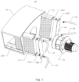
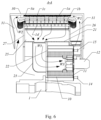
- an embodiment of the present application provides a cooling device 10 integrated inside a motor and including a heat exchanger 11, a circulation fan 12, and a housing 13.
- the housing 13 extends along an axial direction of the motor, has a receiving cavity 130 and an air inlet 1301 and an air outlet 1302 in communication with the receiving cavity 130, and is in communication with an interior of the motor through the air inlet 1301 and in communication with ventilation chambers located at two axial ends of the motor through the air outlet 1302.
- the heat exchanger 11 is located in the receiving cavity 130 and provided close to the air outlet 1302, and the circulation fan 12 is provided in the receiving cavity 130 along the axial direction of the motor.
- the heat exchanger 30 may be an air-air or air-liquid heat exchanger.
- the heat exchanger 30 is, for example, but not limited to, a plate-fin, tube-fin, and tubular air-liquid heat exchanger, and the cooling medium in the heat exchanger 30 may be a liquid medium or a phase change medium, and exchanges heat with an external cooling system through a liquid supply pipe 14 and the liquid/air return pipe 15 located outside of the housing 13 to further cool the motor in circulation.
- the cooling air enters the ventilation chambers at the two axial ends of the motor through the air outlet 1302, flows through a heating component inside the motor, and then enters the housing 13 through the air inlet 1301 to exchange heat with the heat exchanger 11.
- the cooling device 10 By providing the heat exchanger 11 and the circulation fan 12 in the housing 13 extending along the axial direction of the motor, the cooling device 10 provided by the embodiments of the present application can realize a modular design of the cooling device 10, has a simple and compact structure, occupies a small space, and may be applied to various devices and apparatus, a motor or the like, that require heat dissipation.
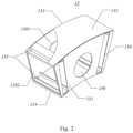
- the housing 13 includes a first plate 131 and a second plate 132, which are provided opposite to each other along the axial direction of the motor, the air inlet 1301 is provided on the second plate 132, and an end of the circulation fan 12 along its own axial direction projects beyond the first plate 131.
- the housing 13 further includes a third plate 133 and a fourth plate 134, which are connected to the first plate 131 and the second plate 132 and provided opposite to each other, and an air outlet 1302 is formed by the first plate 131, the second plate 132, the third plate 133, and the fourth plate 134 at at least one circumferential end of the motor.
- the air outlet 1302 may be formed at two circumferential ends of the motor.
- the third plate 133 and the fourth plate 134 are provided with installation grooves 135 at the two circumferential ends of the motor, the two heat exchangers 11 are detachably installed in the installation grooves 135 of the third plate 133 and the fourth plate 134, and the circulation fan 12 is provided between the two heat exchangers 11, thereby increasing the heat exchange area.
- the first plate 131 is provided with an inspection opening 136 allowing the heat exchanger to pass through, and the first plate 131 covers the inspection opening 136 via a cover plate 16.
- a sealing ring or the like is provided between the cover plate 16 and the inspection opening 136.
- a first joint 111 and a second joint 112 are provided on the heat exchanger 11, the cover plate 16 is provided with a first opening 161 and a second opening 162, the first joint 111 projects beyond the first opening 161 and is connected to the liquid supply pipe 14, and the second joint 112 projects beyond the second opening 162 and is connected to the liquid/air return pipe 15.
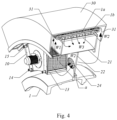
- an embodiment of the present application also provides a motor, the motor includes a stator support 20 and a rotor support 30, which are connected in dynamic sealed manner to form ventilation chambers 31 at two axial ends of the motor, and the motor further includes a confluence chamber 201 and at least one cooling device 10 of any one type as described above.
- the motor can be a structure having an outer rotor and an inner stator or a structure having an outer stator and an inner rotor.
- the stator is fixed on a fixed shaft by the stator support 20, the rotor is fixed on the moving shaft by the rotor support 30, and the fixed shaft and the moving shaft are connected by a bearing to realize relative rotation.
- the fixed shaft and the moving shaft together constitute a main shaft 1 of the motor.
- the description is made in the embodiments of the present application by taking a motor of a structure having the outer rotor and the inner stator as an example.
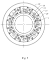
- the stator includes a stator winding 1a and a plurality of stator cores 1b provided at intervals along the axial direction, and a radial channel 1d is formed between every two adjacent stator cores 1b.
- Each of the stator cores 1b includes a yoke part and a tooth part (not shown in the figure) which is integrally formed with the yoke part, the stator winding 1a is wound around the tooth part, and the stator is fixed to the stator support 20 by the yoke part.
- the rotor support 30A is provided with a magnetic steel 3a thereon, and an air gap 1c is formed between the rotor and the stator along the radial direction.
- the stator winding 1a, the stator cores 1b, and the magnetic steel 3a are all heat dissipating components.
- the confluence chamber 201 is provided along the circumferential direction of the stator support 20, at least one cooling device 10 is provided along the circumferential direction of the stator support 20, and the cooling device 10 is located on a radial inner side of the confluence chamber 201 and in communication with the confluence chamber 201 through the air inlet 1301.
- the cooling process of the cooling device 10 is as follows: under the action of the circulation fan 12 in the cooling device 10, the cooling air is introduced from the interior of the motor through the ventilation pipe 23 into the housing 13 of the cooling device 10 such that the heated cooling air exchanges heat with the heat exchanger 11, as shown by the arrow W3 in Fig.
- the heat exchanger 11 is connected to the external cooling system through the liquid supply pipe 14 and the liquid /air return pipe 15 such that the temperature of the cooling air drops to form an airflow with relatively low temperature, and under the negative pressure of the circulating fan 12, a part of the cooling air directly enters the adjacent ventilation chamber 31 at one end, as shown by the arrow W1 in Fig.
- the two parts of cooling air entering into the air gap 1c pass through the plurality of radial channels 1d distributed at intervals along the axial direction of the stator to realize the cooling of the stator winding 1a and the stator yoke, the temperature of the cooling air passing through the radial ventilation channels 1d rises, the high-temperature cooling air enters the cooling device 10 again through the confluence chamber 25 and the ventilation pipe 23 under the action of the circulation fan 12, and a next cooling cycle of the airflow organization performs under the action of the circulation fan 12.
- liquid supply pipe 14 and the liquid/air return pipe 15 of the heat exchanger 11 are located outside the housing 13 of the cooling device 10, which further simplifies the internal structure of the motor, thereby causing the motor to have a simpler and more compact overall structure and to occupy a smaller space.
- the motor provided by the embodiments of the present application can cool the heating components inside the motor in circulation, and has simple and compact overall structure and occupies a small space.
- the circulation fans 12 of two or more cooling devices 10 are provided along the axial direction of the motor to guide the airflow from the heat exchanger 11 to one of the ventilation chambers 31 and to guide the airflow to the other ventilation chamber 31 through the ventilation hole a.
- the volume of the circulation fan 12 can be reduced, and compared with a case, in which an integrated circulation fan provided along the axial direction of the stator support 20, the same heat dissipation effect can be achieved, and also the motor has simple and compact overall structure and occupies a small space.
- the two or more cooling devices 10 are uniformly distributed along the circumferential direction of the stator support 20. Since the ventilation chambers 31 at the two axial ends of the motor have a volume large enough, they can play a role of a static pressure cavity, so the end of the stator winding 1a has a uniform cooling effect and also the uniformity of the airflow entering the air gap 1c along the axial direction is ensured, the cooling air entering the air gap 1c flows along the air gap 1c and also through the stator winding 1a and the radial ventilation channel 1d of the stator core 1b into the confluence chamber 25, and the confluence chamber 25 also has a volume large enough and can play a role of a static pressure cavity, thereby ensuring the uniformity of the airflow in the entire circumferential space, avoiding nonuniform airflow organization, and improving the heat dissipation uniformity of the cooling system.
- the stator support 10 includes a first end plate 26 and a second end plate 27, which extends along the radial direction and is provided opposite to each other along the axial direction, and an annular plate, which is provided between the first end plate 26 and the second end plate 27, and the first end plate 26, the second end plate 27, and the annular plate 21 form a confluence chamber 25 .
- stator support 10 further includes a separation plate 22, which is connected to the annular plate 21 and extends inwardly along the radial direction, at least one ventilation pipe 23 is further provided between the annular plate 21 and the separation plate 22, and the cooling device 10 is provided on the separation plate 22 and in communication with the ventilation pipe 23 through the air inlet 1301.
- the ventilation pipe 23 has an inner wall and an outer wall provided for thermally insulating, so that the cooling air inside the ventilation pipe 23 does not exchange heat with the airflow outside of the ventilation pipe 23 before reaching the housing 13 of the cooling device 10, and a cavity for effectively sealing the airflow organization is formed among the annular plate 21, the stator support 20, the cooling device 10, and the main shaft 1, thereby preventing the cooling air entering the housing 13 through the ventilation pipe 23 from being shortcircuited during the heat exchange with the heat exchanger 11.
- At least one ventilation hole a is provided on the separation plate 22, the two or more cooling devices 10 are provided on the separation plate 22 at intervals along the circumferential direction of the stator support 20, and an isolation chamber is formed between every two adjacent cooling devices 10 (not shown in the figure) and in communication with the ventilation hole a. That is, on the radial inner side of the annular plate 21, the isolation chambers and the housings 13 are alternately disposed along the circumferential direction of the stator support 10.
- each isolation chamber is in communication with the ventilation chambers 31 at the two axial ends of the motor through the ventilation hole a provided on the separation plate 22, so after any one of the circulation fans 12 fails, the other circulation fans 12 can still allow the airflow, which is present at the heat exchanger 11 corresponding to the failed circulation fan 12, to pass through, the heat dissipation requirements of the stator winding 1a, the stator core 1b, and the magnetic steel 3a corresponding to the failed circulation fan 12 can be taken into account, and the reliability and fault tolerance of the motor are improved.
- a filter 24 is provided at the ventilation hole a of the separation plate 22.
- the housing 13 of the cooling device 10 can be used as a reinforcing rib of the stator support 20, thereby improving the structural strength and rigidity of the stator support 20;
- the cooling device 10 is provided on a side of the separation plate 22 as a modular structure and in communication with the external environment, and can be removed directly when the cooling device 10 needs to be replaced or repaired; and if only the heat exchanger 11 needs to be replaced, the cooling device 10 do not have to be removed and only the cover plate 16 on the cooling device 10 needs to be removed, thereby the heat exchanger 11 can be quickly replaced at the inspection opening 136 without removing other components, thereby improving the maintainability of the motor.
- an embodiment of the present application also provides a wind turbine set, which includes a nacelle and a motor as described above, and the circulation fan 12 of the cooling device 10 of the motor is provided on a side of the nacelle, which is convenient for later installation, maintenance, and replacement.
- the wind turbine set provided by the embodiments of the present application adopt the motor described above, which can effectively reduce the size of the nacelle, thereby further reducing the whole machine cost and load and improving the reliability and maintainability of the wind turbine set.
- the motor according to the exemplary embodiments described above can be applied to various apparatus that needs to be provided with a motor, for example, but not limited to, a wind turbine set.
Landscapes
- Engineering & Computer Science (AREA)
- Power Engineering (AREA)
- Life Sciences & Earth Sciences (AREA)
- Sustainable Energy (AREA)
- Sustainable Development (AREA)
- Chemical & Material Sciences (AREA)
- Combustion & Propulsion (AREA)
- Mechanical Engineering (AREA)
- General Engineering & Computer Science (AREA)
- Physics & Mathematics (AREA)
- Thermal Sciences (AREA)
- Motor Or Generator Cooling System (AREA)
Claims (5)
- Kühlvorrichtung (10), die in einen Motor integriert ist,wobei an zwei axialen Enden des Motors Belüftungskammern (31) vorgesehen sind,wobei der Motor einen Rotor und einen Stator umfasst,wobei die Kühlvorrichtung (10) Folgendes umfasst:ein Gehäuse (13), das sich entlang einer axialen Richtung des Motors erstreckt, wobei das Gehäuse (13) einen Aufnahmehohlraum (130) und einen Lufteinlass (1301) und einen Luftauslass (1302) in Kommunikation mit dem Aufnahmehohlraum (130) umfasst, wobei das Gehäuse (13) durch den Lufteinlass (1301) mit einem Innenraum des Motors in Kommunikation steht und durch den Luftauslass (1302) mit den Belüftungskammern (31) in Kommunikation steht;einen Wärmetauscher (11), der sich in dem Aufnahmehohlraum (130) befindet und in der Nähe des Luftauslasses (1302) vorgesehen ist;wobei der Wärmetauscher (11) über ein Flüssigkeitszufuhrrohr (14) und ein Flüssigkeitsrückführrohr (15) mit einem externen Kühlsystem verbunden ist, sodass die Temperatur der Kühlluft abfällt, um einen Luftstrom mit relativ niedriger Temperatur zu bilden,wobei in dem Aufnahmehohlraum (130) entlang der axialen Richtung des Motors ein Umwälzgebläse (12) vorgesehen ist,wobei das Gehäuse (13) eine erste Platte (131) und eine zweite Platte (132) umfasst, die einander gegenüberliegend entlang der axialen Richtung des Motors vorgesehen sind, der Lufteinlass (1301) an der zweiten Platte (132) vorgesehen ist und ein Ende des Umwälzgebläses (12) entlang seiner eigenen axialen Richtung über die erste Platte (131) hinausragt,wobei der Motor einen Statorträger (10) umfasst, der eine erste Endplatte (26) und eine zweite Endplatte (27) beinhaltet, die sich entlang der radialen Richtung des Motors erstrecken und die einander gegenüberliegend entlang der axialen Richtung des Motors vorgesehen sind, wobei der Statorträger ferner eine ringförmige Platte umfasst, die zwischen der ersten Endplatte (26) und der zweiten Endplatte (27) vorgesehen ist,wobei die erste Endplatte (26), die zweite Endplatte (27) und die ringförmige Platte (21) eine Konfluenzkammer (25) bilden,wobei der Statorträger (10) ferner eine Separatorplatte (22) beinhaltet, die mit der ringförmigen Platte (21) verbunden ist und sich entlang der radialen Richtung nach innen erstreckt, wobei ferner mindestens ein Belüftungsrohr (23) zwischen der ringförmigen Platte (21) und der Separatorplatte (22) vorgesehen ist und die Kühlvorrichtung (10) an der Separatorplatte (22) und über den Lufteinlass (1301) in Kommunikation mit dem Belüftungsrohr (23) vorgesehen ist,wobei die Kühlluft unter Einwirkung des Umwälzgebläses (12) in der Kühlvorrichtung (10) aus dem Innenraum des Motors durch das Belüftungsrohr (23) in das Gehäuse (13) der Kühlvorrichtung (10) eingeleitet wird, sodass die erwärmte Kühlluft mit dem Wärmetauscher (11) Wärme austauscht,wobei unter dem Unterdruck des Umwälzgebläses (12) ein Teil der Kühlluft direkt in die benachbarte Belüftungskammer (31) an einem axialen Ende eintritt, um ein Ende der Statorwicklung (1a) zu kühlen, und dann entlang des Luftspalts (1c) strömt, um die Kühlung eines Teils des Magnetstahls (3a), des Rotorjochs und der Statorwicklung (1a) zu realisieren,wobei der andere Teil der Kühlluft in die Belüftungskammer (31) am anderen Ende des Motors durch ein Belüftungsloch a an der Separatorplatte (22) eintritt, um das andere Ende der Statorwicklung (1a) zu kühlen, und dann entlang des Luftspalts (1c) strömt, um die Kühlung des anderen Teils des Magnetstahls (3a), des Rotorjochs und der Statorwicklung (1a) zu realisieren.
- Kühlvorrichtung (10) nach Anspruch 1, wobei das Gehäuse (13) ferner eine dritte Platte (133) und eine vierte Platte (134) umfasst, die mit der ersten Platte (131) und der zweiten Platte (132) verbunden und einander gegenüberliegend vorgesehen sind, und der Luftauslass (1302) durch die erste Platte (131), die zweite Platte (132), die dritte Platte (133) und die vierte Platte (134) an mindestens einem Umfangsende des Motors ausgebildet ist.
- Kühlvorrichtung (10) nach Anspruch 2, wobei die dritte Platte (133) und die vierte Platte (134) an zwei Umfangsenden des Motors mit Installationsrillen (135) versehen sind, zwei Wärmetauscher (11) in den Installationsrillen (135) der dritten Platte (133) und der vierten Platte (134) lösbar installiert sind und das Umwälzgebläse (12) zwischen den zwei Wärmetauschern (11) vorgesehen ist.
- Kühlvorrichtung (10) nach einem der Ansprüche 1 bis 3, wobei an der ersten Platte eine Inspektionsöffnung (136) vorgesehen ist, um den Wärmetauscher (11) passieren zu lassen, und die erste Platte (131) die Inspektionsöffnung (136) über eine Abdeckplatte abdeckt.
- Windturbinensatz, der ein Maschinenhaus und die Kühlvorrichtung nach einem der Ansprüche 1-4 beinhaltet, wobei das Umwälzgebläse der Kühlvorrichtung auf einer Seite des Maschinenhauses vorgesehen ist.
Applications Claiming Priority (2)
| Application Number | Priority Date | Filing Date | Title |
|---|---|---|---|
| CN201910364180.4A CN111864992B (zh) | 2019-04-30 | 2019-04-30 | 冷却装置、电机及风力发电机组 |
| PCT/CN2020/078431 WO2020220836A1 (zh) | 2019-04-30 | 2020-03-09 | 冷却装置、电机及风力发电机组 |
Publications (4)
| Publication Number | Publication Date |
|---|---|
| EP3955434A1 EP3955434A1 (de) | 2022-02-16 |
| EP3955434A4 EP3955434A4 (de) | 2022-06-15 |
| EP3955434C0 EP3955434C0 (de) | 2024-12-04 |
| EP3955434B1 true EP3955434B1 (de) | 2024-12-04 |
Family
ID=72966693
Family Applications (1)
| Application Number | Title | Priority Date | Filing Date |
|---|---|---|---|
| EP20798535.9A Active EP3955434B1 (de) | 2019-04-30 | 2020-03-09 | Kühlvorrichtung, motor und windturbinengeneratorsatz |
Country Status (6)
| Country | Link |
|---|---|
| US (1) | US12049872B2 (de) |
| EP (1) | EP3955434B1 (de) |
| CN (1) | CN111864992B (de) |
| AU (1) | AU2020266898B2 (de) |
| ES (1) | ES3000103T3 (de) |
| WO (1) | WO2020220836A1 (de) |
Families Citing this family (8)
| Publication number | Priority date | Publication date | Assignee | Title |
|---|---|---|---|---|
| CN114665662B (zh) * | 2020-12-23 | 2024-09-13 | 金风科技股份有限公司 | 发电机以及风力发电机组 |
| CN114696537B (zh) * | 2020-12-30 | 2024-01-26 | 北京金风科创风电设备有限公司 | 用于风力发电机组的冷却系统及风力发电机组 |
| CN113991940B (zh) * | 2021-11-04 | 2025-04-18 | 南昌三瑞智能科技股份有限公司 | 一种集成内部散热的外转子无刷电机及飞行器 |
| CN113991939B (zh) * | 2021-11-04 | 2022-05-17 | 南昌三瑞智能科技有限公司 | 一种集成分体式液冷散热模块的动力系统及其飞行器 |
| CN113746233B (zh) * | 2021-11-04 | 2022-01-25 | 南昌三瑞智能科技有限公司 | 一种内部集成散热模块的无刷电机及飞行器 |
| CN114552817A (zh) * | 2022-02-25 | 2022-05-27 | 哈电风能有限公司 | 一种发电机冷却结构及发电装置 |
| EP4266556A1 (de) * | 2022-04-22 | 2023-10-25 | Siemens Gamesa Renewable Energy A/S | Kühlkreislauf für einen elektrischen generator |
| CN119182252B (zh) * | 2024-11-22 | 2025-03-21 | 贝肯新能源有限公司 | 一种智能控温散热转子电机 |
Family Cites Families (12)
| Publication number | Priority date | Publication date | Assignee | Title |
|---|---|---|---|---|
| JP4561408B2 (ja) | 2005-03-03 | 2010-10-13 | 株式会社日立製作所 | 回転電機 |
| DK2182618T3 (da) * | 2008-10-28 | 2012-10-29 | Siemens Ag | Anordning til afkøling af en elektrisk maskine |
| EP2403115A1 (de) * | 2009-02-27 | 2012-01-04 | Hitachi, Ltd. | Permanentmagnetgenerator |
| DK2234246T3 (da) * | 2009-03-23 | 2012-12-03 | Abb Oy | Arrangement og fremgangsmåde til køling af et elektrisk apparat |
| US8760017B2 (en) * | 2010-07-05 | 2014-06-24 | Hanning Elektro-Werke Gmbh & Co. Kg | Electric machine |
| CN102290922B (zh) * | 2011-09-06 | 2013-07-10 | 永济新时速电机电器有限责任公司 | 一种双馈风力发电机 |
| KR101499365B1 (ko) | 2013-12-30 | 2015-03-06 | 주식회사 효성 | 고압전동기의 재순환형 열교환기 |
| EP3054569A1 (de) | 2015-02-05 | 2016-08-10 | Siemens Aktiengesellschaft | Kühlanordnung |
| DE102015011863B4 (de) * | 2015-09-10 | 2017-10-05 | Audi Ag | Elektrische Maschine |
| US11073136B2 (en) * | 2017-02-02 | 2021-07-27 | Siemens Gamesa Renewable Energy A/S | Cooling arrangement |
| CN109474113B (zh) * | 2018-09-06 | 2020-06-23 | 新疆金风科技股份有限公司 | 电机及风力发电机组 |
| EP4679682A2 (de) * | 2019-01-10 | 2026-01-14 | Vestas Wind Systems A/S | Verbesserungen im zusammenhang mit der kühlung von stromgeneratoren in windturbinen |
-
2019
- 2019-04-30 CN CN201910364180.4A patent/CN111864992B/zh active Active
-
2020
- 2020-03-09 EP EP20798535.9A patent/EP3955434B1/de active Active
- 2020-03-09 ES ES20798535T patent/ES3000103T3/es active Active
- 2020-03-09 AU AU2020266898A patent/AU2020266898B2/en active Active
- 2020-03-09 WO PCT/CN2020/078431 patent/WO2020220836A1/zh not_active Ceased
- 2020-03-09 US US17/594,862 patent/US12049872B2/en active Active
Also Published As
| Publication number | Publication date |
|---|---|
| EP3955434C0 (de) | 2024-12-04 |
| CN111864992A (zh) | 2020-10-30 |
| US20220213874A1 (en) | 2022-07-07 |
| US12049872B2 (en) | 2024-07-30 |
| ES3000103T3 (en) | 2025-02-27 |
| WO2020220836A1 (zh) | 2020-11-05 |
| AU2020266898B2 (en) | 2023-04-20 |
| EP3955434A1 (de) | 2022-02-16 |
| AU2020266898A1 (en) | 2021-12-09 |
| CN111864992B (zh) | 2024-10-25 |
| EP3955434A4 (de) | 2022-06-15 |
Similar Documents
| Publication | Publication Date | Title |
|---|---|---|
| EP3955434B1 (de) | Kühlvorrichtung, motor und windturbinengeneratorsatz | |
| US12316202B2 (en) | Cooling system, electric motor and wind-power electric generator set | |
| EP3379701B1 (de) | Motorrotorstützrahmen und motor | |
| JP5441607B2 (ja) | 電気機械を冷却するための装置 | |
| JP5558780B2 (ja) | 電気機械の冷却のための装置 | |
| JP5358667B2 (ja) | 永久磁石式発電機 | |
| US20100176670A1 (en) | Machine cooling scheme | |
| EP2372881A2 (de) | Drehende elektrische Maschine mit Permanentmagnet und Windenergieerzeugungssystem | |
| CN109450128B (zh) | 一种电机定子和具有该电机定子的油冷电机 | |
| CN105048662A (zh) | 电机的散热 | |
| US11984790B2 (en) | Cooling system, electric motor and wind-power electric generator set | |
| WO2012080566A1 (en) | An electrical machine | |
| CN102237759B (zh) | 电机 | |
| CN110768414A (zh) | 一种永磁电机的冷却结构 | |
| CN120422268A (zh) | 一种基于混合磁通电机的人形机器人关节模组 |
Legal Events
| Date | Code | Title | Description |
|---|---|---|---|
| STAA | Information on the status of an ep patent application or granted ep patent |
Free format text: STATUS: THE INTERNATIONAL PUBLICATION HAS BEEN MADE |
|
| PUAI | Public reference made under article 153(3) epc to a published international application that has entered the european phase |
Free format text: ORIGINAL CODE: 0009012 |
|
| STAA | Information on the status of an ep patent application or granted ep patent |
Free format text: STATUS: REQUEST FOR EXAMINATION WAS MADE |
|
| 17P | Request for examination filed |
Effective date: 20211112 |
|
| AK | Designated contracting states |
Kind code of ref document: A1 Designated state(s): AL AT BE BG CH CY CZ DE DK EE ES FI FR GB GR HR HU IE IS IT LI LT LU LV MC MK MT NL NO PL PT RO RS SE SI SK SM TR |
|
| REG | Reference to a national code |
Ref country code: DE Ref legal event code: R079 Free format text: PREVIOUS MAIN CLASS: H02K0009060000 Ipc: H02K0009080000 Ref country code: DE Ref legal event code: R079 Ref document number: 602020042610 Country of ref document: DE Free format text: PREVIOUS MAIN CLASS: H02K0009060000 Ipc: H02K0009080000 |
|
| A4 | Supplementary search report drawn up and despatched |
Effective date: 20220512 |
|
| RIC1 | Information provided on ipc code assigned before grant |
Ipc: H02K 7/18 20060101ALI20220506BHEP Ipc: H02K 9/08 20060101AFI20220506BHEP |
|
| DAV | Request for validation of the european patent (deleted) | ||
| DAX | Request for extension of the european patent (deleted) | ||
| STAA | Information on the status of an ep patent application or granted ep patent |
Free format text: STATUS: EXAMINATION IS IN PROGRESS |
|
| 17Q | First examination report despatched |
Effective date: 20230125 |
|
| RAP3 | Party data changed (applicant data changed or rights of an application transferred) |
Owner name: GOLDWIND SCIENCE & TECHNOLOGY CO., LTD. |
|
| GRAP | Despatch of communication of intention to grant a patent |
Free format text: ORIGINAL CODE: EPIDOSNIGR1 |
|
| STAA | Information on the status of an ep patent application or granted ep patent |
Free format text: STATUS: GRANT OF PATENT IS INTENDED |
|
| INTG | Intention to grant announced |
Effective date: 20240725 |
|
| GRAS | Grant fee paid |
Free format text: ORIGINAL CODE: EPIDOSNIGR3 |
|
| GRAA | (expected) grant |
Free format text: ORIGINAL CODE: 0009210 |
|
| STAA | Information on the status of an ep patent application or granted ep patent |
Free format text: STATUS: THE PATENT HAS BEEN GRANTED |
|
| AK | Designated contracting states |
Kind code of ref document: B1 Designated state(s): AL AT BE BG CH CY CZ DE DK EE ES FI FR GB GR HR HU IE IS IT LI LT LU LV MC MK MT NL NO PL PT RO RS SE SI SK SM TR |
|
| REG | Reference to a national code |
Ref country code: CH Ref legal event code: EP |
|
| REG | Reference to a national code |
Ref country code: DE Ref legal event code: R096 Ref document number: 602020042610 Country of ref document: DE |
|
| REG | Reference to a national code |
Ref country code: IE Ref legal event code: FG4D |
|
| U01 | Request for unitary effect filed |
Effective date: 20241223 |
|
| U07 | Unitary effect registered |
Designated state(s): AT BE BG DE DK EE FI FR IT LT LU LV MT NL PT RO SE SI Effective date: 20250114 |
|
| REG | Reference to a national code |
Ref country code: ES Ref legal event code: FG2A Ref document number: 3000103 Country of ref document: ES Kind code of ref document: T3 Effective date: 20250227 |
|
| U20 | Renewal fee for the european patent with unitary effect paid |
Year of fee payment: 6 Effective date: 20250220 |
|
| PG25 | Lapsed in a contracting state [announced via postgrant information from national office to epo] |
Ref country code: HR Free format text: LAPSE BECAUSE OF FAILURE TO SUBMIT A TRANSLATION OF THE DESCRIPTION OR TO PAY THE FEE WITHIN THE PRESCRIBED TIME-LIMIT Effective date: 20241204 |
|
| PG25 | Lapsed in a contracting state [announced via postgrant information from national office to epo] |
Ref country code: NO Free format text: LAPSE BECAUSE OF FAILURE TO SUBMIT A TRANSLATION OF THE DESCRIPTION OR TO PAY THE FEE WITHIN THE PRESCRIBED TIME-LIMIT Effective date: 20250304 |
|
| PG25 | Lapsed in a contracting state [announced via postgrant information from national office to epo] |
Ref country code: GR Free format text: LAPSE BECAUSE OF FAILURE TO SUBMIT A TRANSLATION OF THE DESCRIPTION OR TO PAY THE FEE WITHIN THE PRESCRIBED TIME-LIMIT Effective date: 20250305 |
|
| PG25 | Lapsed in a contracting state [announced via postgrant information from national office to epo] |
Ref country code: RS Free format text: LAPSE BECAUSE OF FAILURE TO SUBMIT A TRANSLATION OF THE DESCRIPTION OR TO PAY THE FEE WITHIN THE PRESCRIBED TIME-LIMIT Effective date: 20250304 |
|
| PGFP | Annual fee paid to national office [announced via postgrant information from national office to epo] |
Ref country code: TR Payment date: 20250228 Year of fee payment: 6 |
|
| PG25 | Lapsed in a contracting state [announced via postgrant information from national office to epo] |
Ref country code: SM Free format text: LAPSE BECAUSE OF FAILURE TO SUBMIT A TRANSLATION OF THE DESCRIPTION OR TO PAY THE FEE WITHIN THE PRESCRIBED TIME-LIMIT Effective date: 20241204 |
|
| PG25 | Lapsed in a contracting state [announced via postgrant information from national office to epo] |
Ref country code: PL Free format text: LAPSE BECAUSE OF FAILURE TO SUBMIT A TRANSLATION OF THE DESCRIPTION OR TO PAY THE FEE WITHIN THE PRESCRIBED TIME-LIMIT Effective date: 20241204 |
|
| PGFP | Annual fee paid to national office [announced via postgrant information from national office to epo] |
Ref country code: ES Payment date: 20250411 Year of fee payment: 6 |
|
| PG25 | Lapsed in a contracting state [announced via postgrant information from national office to epo] |
Ref country code: IS Free format text: LAPSE BECAUSE OF FAILURE TO SUBMIT A TRANSLATION OF THE DESCRIPTION OR TO PAY THE FEE WITHIN THE PRESCRIBED TIME-LIMIT Effective date: 20250404 |
|
| PG25 | Lapsed in a contracting state [announced via postgrant information from national office to epo] |
Ref country code: SK Free format text: LAPSE BECAUSE OF FAILURE TO SUBMIT A TRANSLATION OF THE DESCRIPTION OR TO PAY THE FEE WITHIN THE PRESCRIBED TIME-LIMIT Effective date: 20241204 |
|
| PG25 | Lapsed in a contracting state [announced via postgrant information from national office to epo] |
Ref country code: CZ Free format text: LAPSE BECAUSE OF FAILURE TO SUBMIT A TRANSLATION OF THE DESCRIPTION OR TO PAY THE FEE WITHIN THE PRESCRIBED TIME-LIMIT Effective date: 20241204 |
|
| PLBE | No opposition filed within time limit |
Free format text: ORIGINAL CODE: 0009261 |
|
| STAA | Information on the status of an ep patent application or granted ep patent |
Free format text: STATUS: NO OPPOSITION FILED WITHIN TIME LIMIT |
|
| PG25 | Lapsed in a contracting state [announced via postgrant information from national office to epo] |
Ref country code: MC Free format text: LAPSE BECAUSE OF FAILURE TO SUBMIT A TRANSLATION OF THE DESCRIPTION OR TO PAY THE FEE WITHIN THE PRESCRIBED TIME-LIMIT Effective date: 20241204 |
|
| REG | Reference to a national code |
Ref country code: CH Ref legal event code: L10 Free format text: ST27 STATUS EVENT CODE: U-0-0-L10-L00 (AS PROVIDED BY THE NATIONAL OFFICE) Effective date: 20251015 |
|
| REG | Reference to a national code |
Ref country code: CH Ref legal event code: H13 Free format text: ST27 STATUS EVENT CODE: U-0-0-H10-H13 (AS PROVIDED BY THE NATIONAL OFFICE) Effective date: 20251023 |
|
| 26N | No opposition filed |
Effective date: 20250905 |
|
| GBPC | Gb: european patent ceased through non-payment of renewal fee |
Effective date: 20250309 |
|
| PG25 | Lapsed in a contracting state [announced via postgrant information from national office to epo] |
Ref country code: GB Free format text: LAPSE BECAUSE OF NON-PAYMENT OF DUE FEES Effective date: 20250309 |
|
| PG25 | Lapsed in a contracting state [announced via postgrant information from national office to epo] |
Ref country code: CH Free format text: LAPSE BECAUSE OF NON-PAYMENT OF DUE FEES Effective date: 20250331 |
|
| PG25 | Lapsed in a contracting state [announced via postgrant information from national office to epo] |
Ref country code: IE Free format text: LAPSE BECAUSE OF NON-PAYMENT OF DUE FEES Effective date: 20250309 |
|
| U20 | Renewal fee for the european patent with unitary effect paid |
Year of fee payment: 7 Effective date: 20260209 |