EP3954908A1 - Connector - Google Patents
Connector Download PDFInfo
- Publication number
- EP3954908A1 EP3954908A1 EP21190622.7A EP21190622A EP3954908A1 EP 3954908 A1 EP3954908 A1 EP 3954908A1 EP 21190622 A EP21190622 A EP 21190622A EP 3954908 A1 EP3954908 A1 EP 3954908A1
- Authority
- EP
- European Patent Office
- Prior art keywords
- connector
- base plate
- coupling piece
- connector according
- channel
- Prior art date
- Legal status (The legal status is an assumption and is not a legal conclusion. Google has not performed a legal analysis and makes no representation as to the accuracy of the status listed.)
- Granted
Links
- 230000008878 coupling Effects 0.000 claims abstract description 49
- 238000010168 coupling process Methods 0.000 claims abstract description 49
- 238000005859 coupling reaction Methods 0.000 claims abstract description 49
- 230000007423 decrease Effects 0.000 claims description 5
- 238000010586 diagram Methods 0.000 description 16
- 238000000034 method Methods 0.000 description 7
- 238000000926 separation method Methods 0.000 description 6
- 239000000463 material Substances 0.000 description 5
- 239000007769 metal material Substances 0.000 description 5
- 238000013459 approach Methods 0.000 description 3
- 230000000694 effects Effects 0.000 description 3
- 239000002184 metal Substances 0.000 description 3
- 238000005266 casting Methods 0.000 description 2
- 238000001746 injection moulding Methods 0.000 description 2
- 238000003466 welding Methods 0.000 description 2
- 238000012986 modification Methods 0.000 description 1
- 230000004048 modification Effects 0.000 description 1
- 230000000452 restraining effect Effects 0.000 description 1
Images


Classifications
-
- F—MECHANICAL ENGINEERING; LIGHTING; HEATING; WEAPONS; BLASTING
- F16—ENGINEERING ELEMENTS AND UNITS; GENERAL MEASURES FOR PRODUCING AND MAINTAINING EFFECTIVE FUNCTIONING OF MACHINES OR INSTALLATIONS; THERMAL INSULATION IN GENERAL
- F16B—DEVICES FOR FASTENING OR SECURING CONSTRUCTIONAL ELEMENTS OR MACHINE PARTS TOGETHER, e.g. NAILS, BOLTS, CIRCLIPS, CLAMPS, CLIPS OR WEDGES; JOINTS OR JOINTING
- F16B5/00—Joining sheets or plates, e.g. panels, to one another or to strips or bars parallel to them
- F16B5/06—Joining sheets or plates, e.g. panels, to one another or to strips or bars parallel to them by means of clamps or clips
- F16B5/0607—Joining sheets or plates, e.g. panels, to one another or to strips or bars parallel to them by means of clamps or clips joining sheets or plates to each other
- F16B5/0621—Joining sheets or plates, e.g. panels, to one another or to strips or bars parallel to them by means of clamps or clips joining sheets or plates to each other in parallel relationship
- F16B5/0657—Joining sheets or plates, e.g. panels, to one another or to strips or bars parallel to them by means of clamps or clips joining sheets or plates to each other in parallel relationship at least one of the plates providing a raised structure, e.g. of the doghouse type, for connection with the clamps or clips of the other plate
-
- F—MECHANICAL ENGINEERING; LIGHTING; HEATING; WEAPONS; BLASTING
- F16—ENGINEERING ELEMENTS AND UNITS; GENERAL MEASURES FOR PRODUCING AND MAINTAINING EFFECTIVE FUNCTIONING OF MACHINES OR INSTALLATIONS; THERMAL INSULATION IN GENERAL
- F16B—DEVICES FOR FASTENING OR SECURING CONSTRUCTIONAL ELEMENTS OR MACHINE PARTS TOGETHER, e.g. NAILS, BOLTS, CIRCLIPS, CLAMPS, CLIPS OR WEDGES; JOINTS OR JOINTING
- F16B21/00—Means for preventing relative axial movement of a pin, spigot, shaft or the like and a member surrounding it; Stud-and-socket releasable fastenings
- F16B21/02—Releasable fastening devices locking by rotation
-
- F—MECHANICAL ENGINEERING; LIGHTING; HEATING; WEAPONS; BLASTING
- F16—ENGINEERING ELEMENTS AND UNITS; GENERAL MEASURES FOR PRODUCING AND MAINTAINING EFFECTIVE FUNCTIONING OF MACHINES OR INSTALLATIONS; THERMAL INSULATION IN GENERAL
- F16B—DEVICES FOR FASTENING OR SECURING CONSTRUCTIONAL ELEMENTS OR MACHINE PARTS TOGETHER, e.g. NAILS, BOLTS, CIRCLIPS, CLAMPS, CLIPS OR WEDGES; JOINTS OR JOINTING
- F16B21/00—Means for preventing relative axial movement of a pin, spigot, shaft or the like and a member surrounding it; Stud-and-socket releasable fastenings
- F16B21/09—Releasable fastening devices with a stud engaging a keyhole slot
-
- F—MECHANICAL ENGINEERING; LIGHTING; HEATING; WEAPONS; BLASTING
- F41—WEAPONS
- F41C—SMALLARMS, e.g. PISTOLS, RIFLES; ACCESSORIES THEREFOR
- F41C33/00—Means for wearing or carrying smallarms
- F41C33/006—Clips, hooks or the like, for carrying the weight of smallarms
-
- H—ELECTRICITY
- H04—ELECTRIC COMMUNICATION TECHNIQUE
- H04N—PICTORIAL COMMUNICATION, e.g. TELEVISION
- H04N23/00—Cameras or camera modules comprising electronic image sensors; Control thereof
- H04N23/57—Mechanical or electrical details of cameras or camera modules specially adapted for being embedded in other devices
-
- A—HUMAN NECESSITIES
- A45—HAND OR TRAVELLING ARTICLES
- A45F—TRAVELLING OR CAMP EQUIPMENT: SACKS OR PACKS CARRIED ON THE BODY
- A45F5/00—Holders or carriers for hand articles; Holders or carriers for use while travelling or camping
- A45F5/02—Fastening articles to the garment
- A45F2005/025—Fastening articles to the garment with a holder or item rotatably connected to the fastening device, e.g. having a rotation axis perpendicular to the garment
- A45F2005/026—Fastening articles to the garment with a holder or item rotatably connected to the fastening device, e.g. having a rotation axis perpendicular to the garment with a pin having an enlarged head detachably connected to a fastening device, e.g. to a pin receiving slot
-
- F—MECHANICAL ENGINEERING; LIGHTING; HEATING; WEAPONS; BLASTING
- F16—ENGINEERING ELEMENTS AND UNITS; GENERAL MEASURES FOR PRODUCING AND MAINTAINING EFFECTIVE FUNCTIONING OF MACHINES OR INSTALLATIONS; THERMAL INSULATION IN GENERAL
- F16B—DEVICES FOR FASTENING OR SECURING CONSTRUCTIONAL ELEMENTS OR MACHINE PARTS TOGETHER, e.g. NAILS, BOLTS, CIRCLIPS, CLAMPS, CLIPS OR WEDGES; JOINTS OR JOINTING
- F16B2200/00—Constructional details of connections not covered for in other groups of this subclass
- F16B2200/30—Dovetail-like connections
-
- Y—GENERAL TAGGING OF NEW TECHNOLOGICAL DEVELOPMENTS; GENERAL TAGGING OF CROSS-SECTIONAL TECHNOLOGIES SPANNING OVER SEVERAL SECTIONS OF THE IPC; TECHNICAL SUBJECTS COVERED BY FORMER USPC CROSS-REFERENCE ART COLLECTIONS [XRACs] AND DIGESTS
- Y10—TECHNICAL SUBJECTS COVERED BY FORMER USPC
- Y10T—TECHNICAL SUBJECTS COVERED BY FORMER US CLASSIFICATION
- Y10T403/00—Joints and connections
- Y10T403/16—Joints and connections with adjunctive protector, broken parts retainer, repair, assembly or disassembly feature
- Y10T403/1616—Position or guide means
- Y10T403/1624—Related to joint component
-
- Y—GENERAL TAGGING OF NEW TECHNOLOGICAL DEVELOPMENTS; GENERAL TAGGING OF CROSS-SECTIONAL TECHNOLOGIES SPANNING OVER SEVERAL SECTIONS OF THE IPC; TECHNICAL SUBJECTS COVERED BY FORMER USPC CROSS-REFERENCE ART COLLECTIONS [XRACs] AND DIGESTS
- Y10—TECHNICAL SUBJECTS COVERED BY FORMER USPC
- Y10T—TECHNICAL SUBJECTS COVERED BY FORMER US CLASSIFICATION
- Y10T403/00—Joints and connections
- Y10T403/60—Biased catch or latch
- Y10T403/602—Biased catch or latch by separate spring
Definitions
- Connectors are extensively applied in diversified commercial wearable products, such as smart wearable devices, police body-worn cameras (BWC), bicycle lighting lamps and military equipment.
- a plug of a connector has a metal shrapnel and a placement terminal of a wearable product has a recess, and the two match with each other to accordingly insert the connector into the wearable product and be mounted between structures, so as to be fitted and secured with each other.
- FIG. 1 shows a three-dimensional diagram of a first connector according to a first embodiment of the present invention.
- the connector is applicable to diversified commercial wearable products, such as smart wearable devices, police body-worn cameras (BWC), bicycle lighting lamps and military equipment.
- a connector can be structurally divided into a plug connector and a receptacle connector, and the two may achieve coupling and separation effects by means of the geometric matching between the two.
- a first connector 1 is a plug connector.
- the open end 311 faces downwards (i.e., the positive direction of the y axis)
- the originally limited protrusion 81 contained at the closed end 312 is released from the containment, such that the first connector 1 becomes capable of successfully moving toward the opposite direction of the second direction (i.e., the negative direction of the y axis), until the coupling piece 30 is disengaged from the accommodating groove 72.
- the direction from the closed side 42 to the open side 41 of the guiding channel 40 is the same as the second direction (i.e., the same as the y-axis direction), and is opposite to the direction from the closed end 312 to the open end 311 of the sliding channel 31.
- the direction from the closed side 42 to the open side 41 of the guiding channel 40 is equivalent to the second direction, and is at an included angle from the direction from the closed end 312 to the open end 311 of the sliding channel 31, for example, 90 degrees, 120 degrees or 150 degrees.
- the guiding portion 611 of the second connector 5 has an inclined surface 6111, which is away from the connecting end 61.
- the inclined surface 6111 may be a trapezoidal sloped surface and face the mobile end 821.
- the inclined surface 6111 may also be a triangular sloped surface, a rectangular sloped surface or other polygonal sloped surfaces.
Abstract
Description
- The present invention relates to a connector, and more particularly to a connector that achieves separation by means of rotational withdrawal.
- Connectors are extensively applied in diversified commercial wearable products, such as smart wearable devices, police body-worn cameras (BWC), bicycle lighting lamps and military equipment. A plug of a connector has a metal shrapnel and a placement terminal of a wearable product has a recess, and the two match with each other to accordingly insert the connector into the wearable product and be mounted between structures, so as to be fitted and secured with each other.
- However, due to insufficient rigidity of the shrapnel, the product is susceptible to permanent deformation in case of impact, resulting in a possible removal failure of the product.
- In view of the above, a connector including a base, a connecting part and a coupling piece is provided in one embodiment. One end of the connecting part is connected to the base. The coupling piece is arranged on the other end of the connecting part, and includes a sliding channel. The sliding channel has an open end and a closed end opposite to each other, wherein the open end is located on a side edge of the coupling piece. A maximum linear distance of an outer periphery of the connecting part is less than a maximum linear distance of an outer periphery of the coupling piece.
- A connector including a base plate, two side plates, a front plate and a positioning portion is further provided. The two side plates are arranged on the base plate, and are parallel to each other. The front plate is connected to the two side plates, and has a tapered positioning slot. The base plate, the two side plates and the front plate form an accommodating groove. The positioning portion is arranged on the base plate, and is adapted for reciprocal movement in a first direction perpendicular to the base plate.
- In conclusion, the connectors provided by the embodiments of the present invention are, by means of rotational withdrawal, capable of preventing deformation of the positioning portion during a separation process, so as to reduce the probability of permanent deformation of the positioning portion to thereby improve the proper rate and durability of a product.
-
-
FIG. 1 is a three-dimensional diagram of a first connector according to a first embodiment of the present invention; -
FIG. 2 is a top view of a first connector according to the first embodiment of the present invention; -
FIG. 3 is a section view of a first connector according to the first embodiment of the present invention; -
FIG. 4 is a three-dimensional diagram of a second connector according to the first embodiment of the present invention; -
FIG. 5 is a section view of a second connector according to the first embodiment of the present invention; -
FIG. 6 is a three-dimensional diagram of a second connector according to a second embodiment of the present invention; -
FIG. 7 is a section view of a second connector according to the second embodiment of the present invention; -
FIG. 8 is a first operation diagram of a connector according to the first embodiment of the present invention; -
FIG. 9 is a second operation diagram of a connector according to the first embodiment of the present invention; -
FIG. 10 is a third operation diagram of a connector according to the first embodiment of the present invention; -
FIG. 11 is a fourth operation diagram of a connector according to the first embodiment of the present invention; -
FIG. 12 is a fifth operation diagram of a connector according to the first embodiment of the present invention; -
FIG. 13 is a first operation section view a connector according to the first embodiment of the present invention; -
FIG. 14 is a second operation section view a connector according to the first embodiment of the present invention; -
FIG. 15 is a third operation section view a connector according to the first embodiment of the present invention; -
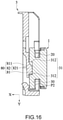
FIG. 16 is a fourth operation section view a connector according to the first embodiment of the present invention; -
FIG. 17 is a fifth operation section view a connector according to the first embodiment of the present invention; -
FIG. 18 is a partial section view of a first connector according to the first embodiment; and -
FIG. 19 is a side view of a first connector according to the first embodiment. -
FIG. 1 shows a three-dimensional diagram of a first connector according to a first embodiment of the present invention. In some embodiments, the connector is applicable to diversified commercial wearable products, such as smart wearable devices, police body-worn cameras (BWC), bicycle lighting lamps and military equipment. A connector can be structurally divided into a plug connector and a receptacle connector, and the two may achieve coupling and separation effects by means of the geometric matching between the two. In the embodiments below, afirst connector 1 is a plug connector. - As shown in
FIG. 1 , thefirst connector 1 includes abase 10, a connectingpart 20 and acoupling piece 30. One end of the connectingpart 20 is connected to thebase 10. Thecoupling piece 30 is arranged on the other end of the connectingpart 20, and includes asliding channel 31. Thesliding channel 31 has anopen end 311 and a closedend 312 opposite to each other, wherein theopen end 311 is located on a side edge of thecoupling piece 30. As shown inFIG. 1 , the side edge refers to any side along the outer periphery of thecoupling piece 30. In this embodiment, if thecoupling piece 30 is circular for example, the side edge is any position on the circumference; if thecoupling piece 30 is rectangular, polygonal or irregularly shaped, the side edge is any side. In this embodiment, thefirst connector 1 may be integrally formed of, for example, a plastic material, by injection molding. Thebase 10 is rectangle in shape, and the geometry of the back side may be correspondingly designed according to a product to be loaded. In other embodiments, thebase 10 of thefirst connector 1 may also be a circle, or a polygon such as a triangle or a pentagon in shape. In some embodiments, thefirst connector 1 may also be integrally formed of a metal material by casting. In other embodiments, thefirst connector 1 may also be formed of hybrid materials (e.g., thebase 10 is formed of a plastic material, and the connectingpart 20 and thecoupling piece 30 are formed of metal materials) and be joined and fixed by means of locking, riveting or welding. -
FIG. 2 shows a top view of a first connector according to the first embodiment of the present invention.FIG. 3 shows a section view of a first connector according to the first embodiment of the present invention. As shown inFIG. 1 to FIG. 3 , a maximum linear distance L2 of the outer periphery of the connectingpart 20 of thefirst connector 1 is less than a maximum linear distance L1 of the outer periphery of thecoupling piece 30. For example, in this embodiment, it is discovered that the maximum linear distance of the outer periphery of thecoupling piece 30 is L1 when viewing thecoupling piece 30 from the top view inFIG. 2 , and the maximum linear distance of the outer periphery of the connectingpart 20 from a top view of a cross section 3-3 inFIG. 3 is L2, and it is found that L2 is less than L1. -
FIG. 4 shows a three-dimensional diagram of a second connector according to the first embodiment of the present invention.FIG. 5 shows a section view of a second connector according to the first embodiment of the present invention.FIG. 6 shows a three-dimensional diagram of a second connector according to a second embodiment of the present invention.FIG. 7 shows a section view of a second connector according to the second embodiment of the present invention. Asecond connector 5 is the foregoing receptacle connector. For better illustration, xyz coordinates are marked where necessary in the drawings, as shown inFIG. 4 . In the description below, a first direction is the x-axis direction, a second direction is the y-axis direction, a third direction is the z-axis direction, and the axes are perpendicular to one another. - As shown in
FIG. 4 to FIG 7 , thesecond connector 5 includes abase plate 50, twoside plates 60, afront plate 70 and apositioning portion 80. The twoside plates 60 are arranged on thebase plate 50, and are parallel to each other. Thefront plate 70 is connected to the twoside plates 60, and has a taperedpositioning slot 71. Thebase plate 50, the twoside plates 60 and thefront plate 70 form anaccommodating groove 72. The positioningportion 80 is arranged on thebase plate 50 and is adapted for reciprocal movement in a first direction perpendicular to thebase plate 50. In the first embodiment, the positioningportion 80 is provided with mobility in the first direction via the design of anelastic arm 82; in the second embodiment, apositioning portion 80a is provided with mobility in the first direction via the configuration of anelastic element 82a - the associated details are to be given shortly. - The
second connector 5 may be formed of a plastic or metal material or other materials. For example, in this embodiment, thesecond connector 5 is integrally formed of a plastic material by injection molding, and thebase plate 50 is a rectangle in shape and has a back surface in a geometric design corresponding to a desired target structure for mounting. In some embodiments, thesecond connector 5 is integrally formed of a metal material by casting, or joined and made from multiple metal sheets formed by metal stamping. In some embodiments, thebase plate 50 of thesecond connector 5 may also be a circle in shape or a polygon such as a triangle or a pentagon in shape. - As shown in
FIG. 4 and FIG. 5 , the positioningportion 80 includes abump 81 and anelastic arm 82. Theelastic arm 82 is connected to thebase 50, and includes amobile end 821 on the side away from thebase plate 50. Thebump 81 is provided on themobile end 821. In this embodiment, thebase plate 50 and the twoside plates 60 are only partially connected; the part by which theelastic arm 82 that is directly connected to thebase plate 50 is a fixed end, and the part on the other side that is not connected is themobile end 821. Thebump 81 is a cylindrical block, thebump 81 and themobile end 82 are integrally formed, and thebump 81 is provided with mobility in the first direction (i.e., the x-axis direction) since the binding force of themobile end 821 is weak. In some embodiments, the length of the connecting part and the length of the non-connecting part of thebase plate 50 and the twoside plates 60 may also be in other proportions, such as 2:1, 1:1, 1:2 and 1:3. If theelastic arm 82 needs a greater flexibility, the length of the non-connecting part may be set to be longer than the length of the connecting part, and vice versa, the length of the non-connecting part may be set to be shorter than the length of the connecting part, which depends on utilization requirements and is not specifically limited herein. - Referring to
FIG. 6 and FIG. 7 , the second embodiment shown inFIG. 6 and FIG. 7 differs from the foregoing fist embodiment by the structure of the positioning portion. Details of the remaining structures can be referred from the first embodiment and are omitted herein. In this embodiment, thepositioning portion 80a includes a protrudingcolumn 81a and anelastic element 82a, the protrudingcolumn 81a is protrudingly disposed on thebase plate 50, one end of theelastic element 82a abuts against thebase plate 50 and the other end abuts against the protrudingcolumn 81a, and theelastic element 82a provides theprotruding column 81a with a restoring force. In this embodiment, theelastic element 82a is a spring, with one end fixed at thebase plate 50 and the other end fixed at the protrudingcolumn 81a, and the protrudingcolumn 81a is a cylinder in shape. In some embodiments, the protrudingcolumn 81a may also be formed of a plastic or metal material, and theelastic element 82a may be a shrapnel, a rubber spring or a helical spring fixed between the protrudingcolumn 81a and thebase plate 50 by means of welding, locking and riveting. -
FIG. 8 shows a first operation diagram of a connector according to the first embodiment of the present invention.FIG. 9 shows a second operation diagram of a connector according to the first embodiment of the present invention.FIG. 10 shows a third operation diagram of a connector according to the first embodiment of the present invention.FIG. 11 shows a fourth operation diagram of a connector according to the first embodiment of the present invention.FIG. 12 shows a fifth operation diagram of a connector according to the first embodiment of the present invention.FIG. 13 shows a first operation section view of a connector according to the first embodiment of the present invention.FIG. 14 shows a second operation section view of a connector according to the first embodiment of the present invention.FIG. 15 shows a third operation section view of a connector according to the first embodiment of the present invention.FIG. 16 shows a fourth operation section view of a connector according to the first embodiment of the present invention.FIG. 17 shows a fifth operation section view of a connector according to the first embodiment of the present invention. - As shown in
FIG. 1 ,FIG. 4 ,FIG. 8 to FIG. 10 , andFIG. 13 to FIG. 15 , when thefirst connector 1 is correspondingly assembled along the second direction (i.e., the y-axis direction) to thesecond connector 5, the connectingpart 20 is inserted in the taperedpositioning slot 71 and thecoupling piece 30 is accommodated in theaccommodating groove 72, and as shown inFIG. 15 , the positioningportion 80 abuts against theclosed end 312 of thecoupling piece 30. As shown inFIG. 1 ,FIG. 9 andFIG. 14 , while the connectingpart 20 is being inserted in the taperedpositioning slot 71, theopen end 311 of the slidingchannel 31 faces an opposite direction of the second direction (i.e., a negative direction of the y axis, the top of the drawing). At this point, a lower edge of thecoupling piece 30 that protrudes more toward the first direction than the slidingchannel 31 first presses against the positioningportion 80, and so the positioningportion 80 is deformed and moves along the first direction (i.e., the x-axis direction). As shown inFIG. 15 , when thefirst connector 1 is pushed all the way to the end, the slidingchannel 31 at this point corresponds to the location of thepositioning portion 80. InFIG. 14 , the positioningportion 80 that is pushed and deformed during the pushing of thefirst connector 1 can move along the opposite direction of the first direction (i.e., the negative direction of the x axis in this embodiment), restore its shape and be accommodated in the slidingchannel 31, and have thebump 81 be abutting against theclosed end 312 of thecoupling piece 30. By abutting the positioningportion 80 against theclosed end 312 of thecoupling piece 30, thefirst connector 1 and thesecond connector 5 are bound together. After coupling, even if thefirst connector 1 is operated by applying a force in the opposite direction of the second direction, theclosed end 312 of thecoupling piece 30 abuts against theprotrusion 81 of thepositioning portion 80 and becomes incapable of moving further toward the opposite direction of the second direction, thereby preventing easy release of the connection between thefirst connector 1 and thesecond connector 5 during movement or daily use of thefirst connector 1 and thesecond connector 5. - As shown in
FIG. 1 ,FIG. 4 ,FIG. 10 to FIG. 12 andFIG. 15 to FIG. 17 , when thefirst connector 1 is to be separated from thesecond connector 5 after thefirst connector 1 has been assembled to thesecond connector 5, as shown inFIG. 10 to FIG. 12 , thefirst connector 1 may be rotated by 180 degrees with the first direction as the axis of rotation (i.e., the x-axis direction), and thefirst connector 1 is moved along the second direction away from thesecond connector 5, such that theopen end 311 of the slidingchannel 31 is changed from facing upward to facing downward, as shown inFIG. 17 . Because theopen end 311 faces downwards (i.e., the positive direction of the y axis), the originally limitedprotrusion 81 contained at theclosed end 312 is released from the containment, such that thefirst connector 1 becomes capable of successfully moving toward the opposite direction of the second direction (i.e., the negative direction of the y axis), until thecoupling piece 30 is disengaged from theaccommodating groove 72. - More specifically, in this embodiment, after the
first connector 1 has been assembled to thesecond connector 5, the direction from theclosed end 312 to theopen end 311 of thefirst connector 1 is opposite to the second direction (i.e., the negative direction of the y axis in this embodiment), thefirst connector 1 is rotated by 180 degrees relative to thesecond connector 5, and the direction from theclosed end 312 to theopen end 311 then changes to be the same as the second direction (i.e., the positive direction of the y axis in this embodiment). Thus, when thefirst connector 1 is moved along a direction opposite to the second direction relative to the second connector 5 (i.e., during moving of thefirst connector 1 away from the second connector 5), theclosed end 312 neither touches theposition portion 80 nor causes deformation of thepositioning portion 80, and the locking between thefirst connector 1 and thesecond connector 5 is easily released to separate the two. In other embodiments, the direction from theclosed end 312 to theopen end 311 of thefirst connector 1 may also be set to have an included angle relative to the second direction, e.g., 90 degrees, 120 degrees or 150 degrees. Accordingly, to separate thefirst connector 1 and thesecond connector 5, rotation of 90 degrees, 120 degrees or 150 degrees using the first direction as the axis of rotation needs to be first performed in order to achieve withdrawal and separation. - Thus, using the geometrical design of the structures of the
first connector 1 and thesecond connector 5, deformation of the positioning portion (80, 80a) during the separation of the two is prevented by rotational withdrawal, so as to reduce the probability of permanent damage of the positioning portion (80, 80a) to thereby enhance the proper rate and durability of a product. - As shown in
FIG. 1 andFIG. 2 , theclosed end 312 of the slidingchannel 31 of thefirst connector 1 includes a first slopedsurface 3121, a second slopedsurface 3122, afirst side surface 3123, asecond side surface 3124 and acurved surface 3125. Thefirst side surface 3123 is connected between thecurved surface 3125 and the first slopedsurface 3121, thesecond side surface 3124 is connected between thecurved surface 3125 and the second slopedsurface 3122, and a distance L3 between the first slopedsurface 3121 and the second slopedsurface 3122 gradually increases from thecurved surface 3125 toward theopen end 311. For example, in this embodiment, on an upper surface P1, a distance L31 between the first slopedsurface 3121 and the second slopedsurface 3122 at theopen end 311 is more than a distance L32 between the first slopedsurface 3121 and the second slopedsurface 3122 at an intersection of the first slopedsurface 3121 and thefirst side surface 3123 and an intersection between the second slopedsurface 3122 and thesecond side surface 3124. Thus, by configuring the distance between the first slopedsurface 3121 and the second slopedsurface 3122 to be gradually increasing from thecurved surface 3125 toward theopen end 311, a user is allowed to adopt another assembly approach for better operation, wherein the another assembly approach is as described below. Theopen end 311 of thefirst connector 1 is aligned with thepositioning portion 80 of thesecond connector 5 and is pushed along the second direction. With the guidance of the first slopedsurface 3121 and the second slopedsurface 3122, the positioningportion 80 is smoothly received in the slidingchannel 31 and be pushed and positioned, and then to be rotated to complete the assembly. In this embodiment, the first slopedsurface 3121 and the second slopedsurface 3122 are symmetrical to each other, and thefirst side surface 3123 and thesecond side surface 3124 are symmetrical as well as parallel to each other. In some embodiments, thefirst side surface 3123 and thesecond side surface 3124 may be non-parallel and form an included angle with each other, for example, 30 degrees, 45 degrees or 60 degrees. - As shown in
FIG. 4, FIG. 5 ,FIG. 9 andFIG. 14 , in the first embodiment, theprotrusion 81 of thepositioning portion 80 has aninclined surface 811, which is away from themobile end 821. In this embodiment, a half of thebump 81 is a cylinder in shape, and the other half is a trapezoidal block having theinclined surface 811 and is closer to thebase plate 50 in a direction farther away from themobile end 821. In other embodiments, theinclined surface 811 may also be an ellipsoidal inclined surface, a triangular inclined surface and other polygonal inclined surfaces. - As shown in
FIG. 6 and FIG. 7 , the protrudingcolumn 81a of the second embodiment has aninclined surface 811a on one end away from theelastic element 82a. In this embodiment, the protrudingcolumn 81a has one end as a cylinder in shape, and the other end as theinclined surface 811a that is a trapezoidal cylindrical inclined surface. In other embodiments, theinclined surface 811a may also be an ellipsoidal inclined surface, a triangular inclined surface and other polygonal inclined surfaces. - Thus, with the configuration of the inclined surface (811, 811a) on the positioning portion (80, 80a), when the
first connector 1 is assembled along the second direction to thesecond connector 5, thecoupling piece 30 is enabled to moved and deform the positioning portion (80, 80a) of thesecond connector 5 under the smooth guidance and pushing of the inclined surface (811, 811a). - As shown in
FIG. 1 andFIG. 8 toFIG. 17 , thefirst connector 1 further includes a guidingchannel 40. The guidingtrack 40 includes anopen side 41 and aclosed side 42 that are opposite, and the direction from theclosed side 42 to theopen side 41 of the guidingchannel 40 is different from the direction of theclosed end 312 to theopen end 311 of the slidingchannel 31. Thus, with the configuration of the guidingchannel 40, when thefirst connector 1 is assembled along the second direction to thesecond connector 5, the positioningportion 80 of thesecond connector 5 is smoothly guided and deformed toward the first direction (i.e., the x-axis direction). In this embodiment, the direction from theclosed side 42 to theopen side 41 of the guidingchannel 40 is the same as the second direction (i.e., the same as the y-axis direction), and is opposite to the direction from theclosed end 312 to theopen end 311 of the slidingchannel 31. In other embodiment, the direction from theclosed side 42 to theopen side 41 of the guidingchannel 40 is equivalent to the second direction, and is at an included angle from the direction from theclosed end 312 to theopen end 311 of the slidingchannel 31, for example, 90 degrees, 120 degrees or 150 degrees. - Further, as shown in
FIG. 4 to FIG. 7 , for whether the first embodiment or the second embodiment, end portions between the twoside plates 60 of thesecond connector 5 are connected to each other to form a connectingend 61, which is provided with a guidingportion 611. In this embodiment, the guidingportion 611 includes a cantilever fixed at the connectingend 61, a free end of the cantilever is capable of reciprocal movement along the first direction (i.e., the x-axis direction), and the guidingportion 611 and theprotrusion 81 of thepositioning portion 80 both extend and protrude in a direction opposite to the first direction (i.e., the negative direction of the x axis). In this embodiment, when thefirst connector 1 is correspondingly assembled to thesecond connector 5, the guidingportion 611 is correspondingly received in the guidingchannel 40. Thus, with the geometric matching between the guidingportion 611 of thesecond connector 5 and the guidingchannel 40 of thefirst connector 1, a positioning effect is achieved when the two are being assembled; during a rotation process for separating the two, hand feel of operation can be provided by slightly resistance to remind the user of a rotation position. In some embodiment, the guidingportion 611 includes a compressible elastic member capable of reciprocal movement along the first direction. In other embodiments, theprotrusion 81 of thepositioning portion 80 extends and protrudes opposite to the first direction, while theguide portion 611 extends and protrudes in the first direction. - As shown in
FIG. 1 andFIG. 15 , the slidingchannel 31 and the guidingchannel 40 of thefirst connector 31 are located on the same plane on thecoupling piece 30. In this embodiment, the slidingchannel 31 and the guidingchannel 40 are both located on the upper surface P1 of thecoupling piece 30. In some embodiments, the slidingchannel 31 and the guidingchannel 40 of thefirst connector 31 are located on two opposite parallel surfaces on thecoupling piece 30; for example, the slidingchannel 31 is located on the upper surface P1 of thecoupling piece 30 and the guidingchannel 40 is located on the lower surface P2 of thecoupling piece 30. In other embodiments, the guidingchannel 40 may also in a quantity of two, which are respectively provided on the upper surface P1 and the lower surface P2. - Thus, by configuring the relative positions of the guiding
channel 40 and the slidingchannel 31 of thefirst connector 1 and the position of the guidingportion 611 of thesecond connector 5, multiple design approaches for restraining thefirst connector 1 and thesecond connector 5 are provided so as to respond to different product utilization requirements. - As shown in
FIG. 4, FIG. 5 ,FIG. 15 andFIG. 16 , the guidingportion 611 of thesecond connector 5 has aninclined surface 6111, which is away from the connectingend 61. In this embodiment, theinclined surface 6111 may be a trapezoidal sloped surface and face themobile end 821. In some embodiments, theinclined surface 6111 may also be a triangular sloped surface, a rectangular sloped surface or other polygonal sloped surfaces. Thus, with the geometric matching between theinclined surface 6111 of the guidingportion 611 of thesecond connector 5 and the guidingchannel 40 of thefirst connector 1, the two are allowed to be smoothly assembled to achieve a positioning effect. Moreover, during the rotation process for separating the two, rotation can be smoothly performed. -
FIG. 18 shows a partial section view of a first connector according to the first embodiment of the present invention. As shown inFIG. 1 andFIG. 18 , the guidingchannel 40 of thefirst connector 1 further includes afirst side portion 43 and asecond side portion 44 that are opposite to each other, and a channel bottom 45 at the bottom of the guidingchannel 40. Theclosed side 42 and thechannel bottom 45 are connected to thefirst side portion 43 and thesecond side portion 44, and a depth L4 of the channel bottom 45 gradually increases from theclosed side 42 toward theopen side 41. In this embodiment, the depth L4 of the channel bottom 45 linearly increases from theclosed side 42 toward theopen side 41; for example, a depth L41 of the channel bottom 45 corresponding to theclosed side 42 is less than a depth L42 of the channel bottom 45 corresponding to theopen side 41. In other embodiments, the depth L4 of thechannel bottom 45 may also gradually increase from theclosed side 42 toward theopen side 41 such that thechannel bottom 45 appears as an arc in shape. Thus, during the assembly process of thefirst connector 1 along the second direction to thesecond connector 5, theopen side 41, having a relatively larger depth, of the guidingchannel 40 of thecoupling piece 30 of thefirst connector 1 first touches thepositioning portion 80, and is capable of guiding, as the depth gradually reduces, the positioningportion 80 to gradually displace, deform and move along the first direction, so as to at the same time enhance the proper rate of a product while reducing resistance of the assembly. -
FIG. 19 shows a side view of afirst connector 1 according to the first embodiment of the present invention. As shown inFIG. 1 andFIG. 19 , a linear distance L5 between thefirst side portion 43 and thesecond side portion 44 of the guidingchannel 40 decreases toward thechannel bottom 45. In this embodiment, the linear distance L5 between thefirst side portion 43 and thesecond side portion 44 linearly decreases toward thechannel bottom 45; for example, on the upper surface P1, a linear distance L51 between thefirst side portion 43 and thesecond side portion 44 on the outer periphery of thecoupling piece 30 is more than a linear distance L52 between thefirst side portion 43 and thesecond side portion 44 on thechannel bottom 45. In other embodiments, the outline between thefirst side portion 43 and thesecond side portion 44 may also be an arc, and the distance between the two gradually decreases toward thechannel bottom 45. Thus, during the rotation process of thefirst connector 1 relative to thesecond connector 5, with the foregoing geometrical design of the guidingchannel 40, the guidingchannel 40 of thefirst connector 1 can be guided to smoothly depart from the guidingportion 611 of thesecond connector 5, so as to at the same time enhance the proper rate of a product while reducing the resistance generated during the rotation process. - As shown in
FIG. 1 andFIG. 2 , a distance L6 between thefirst side portion 43 and thesecond side portion 44 of the guidingchannel 40 gradually increases from theclosed side 42 toward theopen side 41. In this embodiment, the distance L6 between thefirst side portion 43 and thesecond side portion 44 linearly increases from theclosed side 42 toward theopen side 41; for example, on the upper surface P1, a distance L61 between thefirst side portion 43 and thesecond side portion 44 at theclosed side 42 is less than a distance L62 betweenfirst side portion 43 and thesecond side portion 44 at theopen side 41. In other embodiments, the outlines of theclosed side 42 and thefirst side portion 43 may also be an arc in shape, or be other geometric shapes. Thus, during the assembly process of thefirst connector 1 along the second direction to thesecond connector 5, theopen side 41 having a larger relative width (i.e., the distance between thefirst side portion 43 and the second side portion 44) of the guidingchannel 40 of thecoupling piece 30 of thefirst connector 1 first touches thepositioning portion 80, and as the width gradually decreases, the guidingportion 80 can be guided to gradually displace, deform and move along the first direction, so as to at the same time enhance the proper rate of a product while reducing the resistance generated during the rotation process. - In conclusion, the connectors provided by the embodiments of the present invention are capable of preventing, by means of rotational withdrawal, deformation of the positioning portion during a separation process, so as to reduce the probability of permanent deformation of the positioning portion to thereby improve the proper rate and durability of a product.
- While the invention has been described by way of example and in terms of the embodiments, it is to be understood that the invention is not limited thereto. Changes and modifications be made by a person skilled in the art without departing from the spirit and scope of the present invention are to be encompassed within the scope of the present invention. Therefore, the scope of protection of the present invention should be accorded with the appended claims.
Claims (15)
- A connector, comprising:a base;a connecting part, having one end thereof connected to the base; anda coupling piece, arranged on one other end of the connecting part, the coupling piece comprising a sliding channel, the sliding channel comprising an open end and a closed end that are opposite to each other, the open end being located on one side edge of the coupling piece;wherein, a maximum linear distance of an outer periphery of the connecting part is less than a maximum linear distance of an outer periphery of the coupling piece.
- The connector according to claim 1, wherein the coupling piece further comprises:a guiding channel, comprising an open side and closed side that are opposite to each other, wherein a direction from the closed side to the open side of the guiding channel is different from a direction from the closed end to the open end of the sliding channel.
- The connector according to claim 2, wherein the sliding channel and the guiding channel are respectively located on two opposite and parallel surfaces on the coupling piece or the sliding channel and the guiding channel are located on a same plane of the coupling piece.
- The connector according to claim 2, wherein the guiding channel further comprises:a first side portion and a second side portion that are opposite to each other, and a channel bottom on a bottom of the channel bottom;wherein, the closed side and the channel bottom are connected to the first side portion and the second side portion, and a depth of the channel bottom gradually increases from the closed side toward the open side.
- The connector according to claim 4, wherein a linear distance between the first side portion and the second side portion gradually decreases toward the channel bottom.
- The connector according to claim 4, wherein a distance between the first side portion and the second side portion gradually increases from the closed side toward the open side.
- The connector according to claim 1, further comprising:another connector, comprising an accommodating groove and a positioning portion, the positioning portion being arranged in the accommodating groove and adapted for reciprocal movement along a first direction;wherein, when the connector is assembled along a second direction to the another connector, the coupling piece is inserted in the accommodating groove and the positioning portion abuts against the closed end of the coupling piece; while the connector is assembled to the another connector, after the connector is rotated by 180 degrees and the connector is moved along the second direction away from the another connector, the coupling piece is disengaged from the accommodating groove;wherein, the first direction and the second direction are perpendicular to each other.
- The connector according to claim 1, further comprising:a base plate;two side plates, arranged on the base plate, respective one ends of the two side plates being arranged parallel to each other;a front plate, connected to the two side plates, the front plate comprising a tapered positioning slot, wherein the base plate, the two side plates and the front plate form an accommodating groove; anda positioning portion, arranged on the base plate, adapted for reciprocal movement along a first direction perpendicular to the base plate;wherein, when the connector is correspondingly assembled along a second direction to the another connector, the connector is inserted in the tapered positioning slot, the coupling piece is accommodated in the accommodating groove, and the positioning portion abuts against the closed end of the coupling piece;wherein, the first direction and the second direction are perpendicular to each other.
- The connector according to claim 7 or 8, wherein the coupling piece further comprises:a guiding slot, comprising an open side and a closed side located on opposite sides;wherein, a direction from the closed side to the open side of the guiding channel is different from a direction from the closed end to the open end of the sliding channel, the another connector further comprises a guiding portion arranged in the accommodating groove, and the guiding portion is correspondingly accommodated in the accommodating groove when the connector is correspondingly assembled to the another connector.
- The connector according to claim 1, wherein the closed end comprises a first sloped surface, a second sloped surface, a first side surface, a second side surface and a curved surface, the first side surface is connected between the curved surface and the first sloped surface, the second side surface is connected between the curved surface and the second sloped surface, and a distance between the first sloped surface and the second sloped surface gradually increases from the curved surface toward the open end.
- A connector, comprising:a base plate;two side plates, arranged on the base plate, the two side plates being arranged parallel to each other;a front plate, connected to the two side plates, the front plate comprising a tapered positioning slot, wherein the base plate, the two side plates and the front plate form an accommodating groove; anda positioning portion, arranged on the base plate, adapted for reciprocal movement along a first direction perpendicular to the base plate.
- The connector according to claim 11, wherein the positioning portion comprises a bump and an elastic arm, the elastic arm is connected to the base plate and has a mobile end on a side away from the base plate, and the bump is arranged at the mobile end.
- The connector according to claim 12, wherein the protrusion has an inclined surface that is away from the mobile end.
- The connector according to claim 11, wherein the positioning portion comprises a protruding column and an elastic element, the protruding column is protrudingly disposed on the base plate, one end of the elastic element abuts against the base plate and one other end abuts against the protruding column, and the elastic element provides the protruding column with a restoring force.
- The connector according to claim 11, wherein an end portion between the two side plates forms a connecting end that is provided with a guiding portion.
Applications Claiming Priority (2)
| Application Number | Priority Date | Filing Date | Title |
|---|---|---|---|
| US202063063865P | 2020-08-10 | 2020-08-10 | |
| CN202011059388.4A CN114321128A (en) | 2020-09-30 | 2020-09-30 | Connecting piece |
Publications (2)
| Publication Number | Publication Date |
|---|---|
| EP3954908A1 true EP3954908A1 (en) | 2022-02-16 |
| EP3954908B1 EP3954908B1 (en) | 2024-01-31 |
Family
ID=77300752
Family Applications (1)
| Application Number | Title | Priority Date | Filing Date |
|---|---|---|---|
| EP21190622.7A Active EP3954908B1 (en) | 2020-08-10 | 2021-08-10 | Connector |
Country Status (2)
| Country | Link |
|---|---|
| US (1) | US11885361B2 (en) |
| EP (1) | EP3954908B1 (en) |
Families Citing this family (8)
| Publication number | Priority date | Publication date | Assignee | Title |
|---|---|---|---|---|
| USD757842S1 (en) * | 2015-05-05 | 2016-05-31 | Gopro, Inc. | Camera mount |
| SE2050181A1 (en) * | 2020-02-18 | 2021-08-03 | Cirk L Ab | Garment with adjustable attachment system allowing for slidable movement of a fastened article |
| USD965669S1 (en) * | 2020-03-16 | 2022-10-04 | Getac Technology Corporation | Camera support |
| USD982065S1 (en) | 2020-06-30 | 2023-03-28 | Gopro, Inc. | Camera mount |
| CN214028816U (en) * | 2020-06-30 | 2021-08-24 | 明门(中国)幼童用品有限公司 | Storage component and infant carrier thereof |
| US20220381395A1 (en) * | 2021-05-28 | 2022-12-01 | Getac Technology Corporation | Installation base |
| US11692649B2 (en) * | 2021-08-06 | 2023-07-04 | A. Raymond Et Cie | Cable routing fastener |
| US11744352B1 (en) * | 2021-12-28 | 2023-09-05 | Glyn Robert Chambers | Belt-attached item holder |
Citations (5)
| Publication number | Priority date | Publication date | Assignee | Title |
|---|---|---|---|---|
| US20030162510A1 (en) * | 2002-02-22 | 2003-08-28 | Kim Dong Joo | Mobile phone holder |
| US20040232180A1 (en) * | 2003-05-19 | 2004-11-25 | Paul Badillo | Belt clip and locking fastener for selectively securing an electronic device |
| GB2414037A (en) * | 2004-05-14 | 2005-11-16 | Motorola Inc | Adaptor for use in carring a mobile communications handset |
| JP4172929B2 (en) * | 2001-10-24 | 2008-10-29 | 株式会社Tjmデザイン | Holder for portable tools |
| GB2575650A (en) * | 2018-07-17 | 2020-01-22 | Peter Jones Ilg Ltd | A connector stud |
Family Cites Families (24)
| Publication number | Priority date | Publication date | Assignee | Title |
|---|---|---|---|---|
| US3743147A (en) * | 1970-12-10 | 1973-07-03 | Motorola Inc | Support for carrying case |
| US4419794A (en) * | 1981-10-05 | 1983-12-13 | Repco Incorporated | Portable fastening device |
| US5026016A (en) * | 1989-12-20 | 1991-06-25 | Helm Products, Inc. | Retainer clip |
| US5054170A (en) * | 1991-03-18 | 1991-10-08 | Otrusina Edward C | Connector engageable in multiple positions and releasable in only one position |
| FI96553B (en) * | 1994-05-18 | 1996-03-29 | Nokia Mobile Phones Ltd | Mobile device mounting device |
| AU4589196A (en) * | 1996-03-04 | 1997-09-11 | Two Thousand And One Technology Inc | Mobile telephone hanging device |
| FI101125B (en) * | 1996-03-28 | 1998-04-30 | Markku Lehtinen | Mounting system for portable device |
| DE19645578C2 (en) * | 1996-11-05 | 1999-03-04 | Kim Dong Joo | Mobile phone holder |
| SE510142C2 (en) * | 1997-06-18 | 1999-04-26 | Aijo Plastic Ab | Apparatus for temporary position fixing of preferably a mobile phone at a carrier |
| US5839173A (en) * | 1997-07-17 | 1998-11-24 | Otrusina; Edward C. | Connector releasable in only one orientation |
| KR200162310Y1 (en) * | 1997-09-20 | 1999-12-15 | 김동주 | The structure of holder for wireless phone |
| KR200189787Y1 (en) * | 1998-06-12 | 2000-08-01 | 김동주 | A mobile phone holder |
| US6283348B1 (en) * | 2000-04-05 | 2001-09-04 | Chin-Yang Wang | Cellular telephone clip |
| JP3429485B2 (en) * | 2000-10-19 | 2003-07-22 | 株式会社バーテックススタンダード | Hook mechanism of portable device to belt clip |
| JP4408595B2 (en) * | 2001-08-08 | 2010-02-03 | パナソニック株式会社 | Mobile phone device holder and in-vehicle holder device |
| US6955279B1 (en) * | 2002-12-04 | 2005-10-18 | Garmin Ltd. | Carrying assembly and method for securement of electronic devices |
| US20050258204A1 (en) * | 2004-05-21 | 2005-11-24 | Evans Michael S | Container with clip for storing and carrying trimmer line strips |
| US8073131B2 (en) * | 2005-01-03 | 2011-12-06 | Fellowes, Inc. | Portable device case with corner protector |
| US8141210B2 (en) * | 2007-02-02 | 2012-03-27 | Juancarlos Colorado | Two-stage quick release interconnect and locking device |
| KR100802061B1 (en) * | 2007-03-30 | 2008-02-12 | 주식회사 뉴빛 | The belt clip for attachable to mobile phone |
| US20090196596A1 (en) * | 2008-02-05 | 2009-08-06 | Andrew Chamberlayne | Camera carrying device |
| US8033518B2 (en) * | 2008-10-08 | 2011-10-11 | Kurt Cameron Schuchman | Beverage holder device |
| US8075202B1 (en) * | 2010-06-07 | 2011-12-13 | Andrew Chamberlayne | Male connector for a camera carrying device |
| GB2496613B (en) * | 2011-11-15 | 2016-08-31 | Buttonfix Ltd | Secret panel fixing set |
-
2021
- 2021-06-25 US US17/359,273 patent/US11885361B2/en active Active
- 2021-08-10 EP EP21190622.7A patent/EP3954908B1/en active Active
Patent Citations (5)
| Publication number | Priority date | Publication date | Assignee | Title |
|---|---|---|---|---|
| JP4172929B2 (en) * | 2001-10-24 | 2008-10-29 | 株式会社Tjmデザイン | Holder for portable tools |
| US20030162510A1 (en) * | 2002-02-22 | 2003-08-28 | Kim Dong Joo | Mobile phone holder |
| US20040232180A1 (en) * | 2003-05-19 | 2004-11-25 | Paul Badillo | Belt clip and locking fastener for selectively securing an electronic device |
| GB2414037A (en) * | 2004-05-14 | 2005-11-16 | Motorola Inc | Adaptor for use in carring a mobile communications handset |
| GB2575650A (en) * | 2018-07-17 | 2020-01-22 | Peter Jones Ilg Ltd | A connector stud |
Also Published As
| Publication number | Publication date |
|---|---|
| US20220045458A1 (en) | 2022-02-10 |
| EP3954908B1 (en) | 2024-01-31 |
| US11885361B2 (en) | 2024-01-30 |
Similar Documents
| Publication | Publication Date | Title |
|---|---|---|
| EP3954908A1 (en) | Connector | |
| US9820404B1 (en) | Slot assembly and workpiece | |
| CN109216989B (en) | Connector terminal assembly and connector | |
| US9231322B2 (en) | Board-connecting electrical connector device | |
| EP1577827B1 (en) | Card connector in which a braking force is varied during a card ejecting process | |
| EP2568539A2 (en) | Conductor connection tool and relay unit using the same | |
| WO2021208571A1 (en) | Power adapter | |
| CN101164201B (en) | Card connector | |
| EP4180912A1 (en) | Casing assembly with an accomodation recess for a stylus | |
| EP2048751A2 (en) | Buffer, adapter, and connecting device for attaching the same buffer or adapter | |
| US20220190504A1 (en) | Connector, connection apparatus and connection method | |
| US8517752B2 (en) | Universal serial bus connector | |
| US20020039676A1 (en) | Battery holder for button-type battery | |
| CN1707866A (en) | Card connector having a retarding mechanism for retarding an ejecting operation of a card | |
| CN107732489A (en) | Connector | |
| KR20190002881U (en) | Wirless charger with holder | |
| US8303322B1 (en) | Card connector anti-misinserting a micro SD card | |
| JPS62177481A (en) | Symmetric type electromagnetic shielding device having bidirectional orbit | |
| CN202513336U (en) | Electronic card connector | |
| CN113936944B (en) | Electronic equipment | |
| CN114321128A (en) | Connecting piece | |
| CN111664155B (en) | Positioning module and electronic device | |
| CN1267070A (en) | Push switch | |
| CN214705607U (en) | Magnetizing carrier | |
| US8705231B2 (en) | Extension device and information processing system including the same |
Legal Events
| Date | Code | Title | Description |
|---|---|---|---|
| PUAI | Public reference made under article 153(3) epc to a published international application that has entered the european phase |
Free format text: ORIGINAL CODE: 0009012 |
|
| STAA | Information on the status of an ep patent application or granted ep patent |
Free format text: STATUS: THE APPLICATION HAS BEEN PUBLISHED |
|
| AK | Designated contracting states |
Kind code of ref document: A1 Designated state(s): AL AT BE BG CH CY CZ DE DK EE ES FI FR GB GR HR HU IE IS IT LI LT LU LV MC MK MT NL NO PL PT RO RS SE SI SK SM TR |
|
| STAA | Information on the status of an ep patent application or granted ep patent |
Free format text: STATUS: REQUEST FOR EXAMINATION WAS MADE |
|
| 17P | Request for examination filed |
Effective date: 20220715 |
|
| RBV | Designated contracting states (corrected) |
Designated state(s): AL AT BE BG CH CY CZ DE DK EE ES FI FR GB GR HR HU IE IS IT LI LT LU LV MC MK MT NL NO PL PT RO RS SE SI SK SM TR |
|
| GRAP | Despatch of communication of intention to grant a patent |
Free format text: ORIGINAL CODE: EPIDOSNIGR1 |
|
| STAA | Information on the status of an ep patent application or granted ep patent |
Free format text: STATUS: GRANT OF PATENT IS INTENDED |
|
| RIC1 | Information provided on ipc code assigned before grant |
Ipc: A45F 5/02 20060101ALN20230724BHEP Ipc: F41C 33/00 20060101ALI20230724BHEP Ipc: F16B 21/09 20060101ALI20230724BHEP Ipc: F16B 21/02 20060101ALI20230724BHEP Ipc: F16B 5/06 20060101AFI20230724BHEP |
|
| RIC1 | Information provided on ipc code assigned before grant |
Ipc: A45F 5/02 20060101ALN20230731BHEP Ipc: F41C 33/00 20060101ALI20230731BHEP Ipc: F16B 21/09 20060101ALI20230731BHEP Ipc: F16B 21/02 20060101ALI20230731BHEP Ipc: F16B 5/06 20060101AFI20230731BHEP |
|
| INTG | Intention to grant announced |
Effective date: 20230817 |
|
| RAP3 | Party data changed (applicant data changed or rights of an application transferred) |
Owner name: GETAC HOLDINGS CORPORATION |
|
| GRAS | Grant fee paid |
Free format text: ORIGINAL CODE: EPIDOSNIGR3 |
|
| RAP3 | Party data changed (applicant data changed or rights of an application transferred) |
Owner name: GETAC HOLDINGS CORPORATION |
|
| GRAA | (expected) grant |
Free format text: ORIGINAL CODE: 0009210 |
|
| STAA | Information on the status of an ep patent application or granted ep patent |
Free format text: STATUS: THE PATENT HAS BEEN GRANTED |
|
| AK | Designated contracting states |
Kind code of ref document: B1 Designated state(s): AL AT BE BG CH CY CZ DE DK EE ES FI FR GB GR HR HU IE IS IT LI LT LU LV MC MK MT NL NO PL PT RO RS SE SI SK SM TR |
|
| REG | Reference to a national code |
Ref country code: GB Ref legal event code: FG4D Ref country code: CH Ref legal event code: EP |
|
| REG | Reference to a national code |
Ref country code: DE Ref legal event code: R096 Ref document number: 602021008905 Country of ref document: DE |
|
| REG | Reference to a national code |
Ref country code: IE Ref legal event code: FG4D |