EP3954650A1 - Verfahren und anlage zur herstellung von wasserstoff und abscheidung von kohlendioxid - Google Patents
Verfahren und anlage zur herstellung von wasserstoff und abscheidung von kohlendioxid Download PDFInfo
- Publication number
- EP3954650A1 EP3954650A1 EP20020366.9A EP20020366A EP3954650A1 EP 3954650 A1 EP3954650 A1 EP 3954650A1 EP 20020366 A EP20020366 A EP 20020366A EP 3954650 A1 EP3954650 A1 EP 3954650A1
- Authority
- EP
- European Patent Office
- Prior art keywords
- gas stream
- reforming
- carbon dioxide
- hydrogen
- unit
- Prior art date
- Legal status (The legal status is an assumption and is not a legal conclusion. Google has not performed a legal analysis and makes no representation as to the accuracy of the status listed.)
- Granted
Links
Images


Classifications
-
- C—CHEMISTRY; METALLURGY
- C01—INORGANIC CHEMISTRY
- C01B—NON-METALLIC ELEMENTS; COMPOUNDS THEREOF; METALLOIDS OR COMPOUNDS THEREOF NOT COVERED BY SUBCLASS C01C
- C01B3/00—Hydrogen; Gaseous mixtures containing hydrogen; Separation of hydrogen from mixtures containing it; Purification of hydrogen; Reversible storage of hydrogen
- C01B3/02—Production of hydrogen; Production of gaseous mixtures containing hydrogen
- C01B3/32—Production of hydrogen; Production of gaseous mixtures containing hydrogen by reaction of gaseous or liquid organic compounds with gasifying agents, e.g. water, carbon dioxide or air
- C01B3/34—Production of hydrogen; Production of gaseous mixtures containing hydrogen by reaction of gaseous or liquid organic compounds with gasifying agents, e.g. water, carbon dioxide or air by reaction of hydrocarbons with gasifying agents
- C01B3/48—Production of hydrogen; Production of gaseous mixtures containing hydrogen by reaction of gaseous or liquid organic compounds with gasifying agents, e.g. water, carbon dioxide or air by reaction of hydrocarbons with gasifying agents followed by reaction of water vapour with carbon monoxide
-
- C—CHEMISTRY; METALLURGY
- C01—INORGANIC CHEMISTRY
- C01B—NON-METALLIC ELEMENTS; COMPOUNDS THEREOF; METALLOIDS OR COMPOUNDS THEREOF NOT COVERED BY SUBCLASS C01C
- C01B3/00—Hydrogen; Gaseous mixtures containing hydrogen; Separation of hydrogen from mixtures containing it; Purification of hydrogen; Reversible storage of hydrogen
- C01B3/02—Production of hydrogen; Production of gaseous mixtures containing hydrogen
- C01B3/32—Production of hydrogen; Production of gaseous mixtures containing hydrogen by reaction of gaseous or liquid organic compounds with gasifying agents, e.g. water, carbon dioxide or air
- C01B3/34—Production of hydrogen; Production of gaseous mixtures containing hydrogen by reaction of gaseous or liquid organic compounds with gasifying agents, e.g. water, carbon dioxide or air by reaction of hydrocarbons with gasifying agents
- C01B3/38—Production of hydrogen; Production of gaseous mixtures containing hydrogen by reaction of gaseous or liquid organic compounds with gasifying agents, e.g. water, carbon dioxide or air by reaction of hydrocarbons with gasifying agents using catalysts
- C01B3/382—Processes with two or more reaction steps, of which at least one is catalytic, e.g. steam reforming and partial oxidation
-
- C—CHEMISTRY; METALLURGY
- C01—INORGANIC CHEMISTRY
- C01B—NON-METALLIC ELEMENTS; COMPOUNDS THEREOF; METALLOIDS OR COMPOUNDS THEREOF NOT COVERED BY SUBCLASS C01C
- C01B3/00—Hydrogen; Gaseous mixtures containing hydrogen; Separation of hydrogen from mixtures containing it; Purification of hydrogen; Reversible storage of hydrogen
- C01B3/02—Production of hydrogen; Production of gaseous mixtures containing hydrogen
- C01B3/32—Production of hydrogen; Production of gaseous mixtures containing hydrogen by reaction of gaseous or liquid organic compounds with gasifying agents, e.g. water, carbon dioxide or air
- C01B3/34—Production of hydrogen; Production of gaseous mixtures containing hydrogen by reaction of gaseous or liquid organic compounds with gasifying agents, e.g. water, carbon dioxide or air by reaction of hydrocarbons with gasifying agents
- C01B3/38—Production of hydrogen; Production of gaseous mixtures containing hydrogen by reaction of gaseous or liquid organic compounds with gasifying agents, e.g. water, carbon dioxide or air by reaction of hydrocarbons with gasifying agents using catalysts
- C01B3/40—Production of hydrogen; Production of gaseous mixtures containing hydrogen by reaction of gaseous or liquid organic compounds with gasifying agents, e.g. water, carbon dioxide or air by reaction of hydrocarbons with gasifying agents using catalysts characterised by the catalyst
-
- B—PERFORMING OPERATIONS; TRANSPORTING
- B01—PHYSICAL OR CHEMICAL PROCESSES OR APPARATUS IN GENERAL
- B01D—SEPARATION
- B01D53/00—Separation of gases or vapours; Recovering vapours of volatile solvents from gases; Chemical or biological purification of waste gases, e.g. engine exhaust gases, smoke, fumes, flue gases, aerosols
- B01D53/02—Separation of gases or vapours; Recovering vapours of volatile solvents from gases; Chemical or biological purification of waste gases, e.g. engine exhaust gases, smoke, fumes, flue gases, aerosols by adsorption, e.g. preparative gas chromatography
- B01D53/04—Separation of gases or vapours; Recovering vapours of volatile solvents from gases; Chemical or biological purification of waste gases, e.g. engine exhaust gases, smoke, fumes, flue gases, aerosols by adsorption, e.g. preparative gas chromatography with stationary adsorbents
- B01D53/047—Pressure swing adsorption
-
- C—CHEMISTRY; METALLURGY
- C01—INORGANIC CHEMISTRY
- C01B—NON-METALLIC ELEMENTS; COMPOUNDS THEREOF; METALLOIDS OR COMPOUNDS THEREOF NOT COVERED BY SUBCLASS C01C
- C01B3/00—Hydrogen; Gaseous mixtures containing hydrogen; Separation of hydrogen from mixtures containing it; Purification of hydrogen; Reversible storage of hydrogen
- C01B3/02—Production of hydrogen; Production of gaseous mixtures containing hydrogen
- C01B3/32—Production of hydrogen; Production of gaseous mixtures containing hydrogen by reaction of gaseous or liquid organic compounds with gasifying agents, e.g. water, carbon dioxide or air
- C01B3/34—Production of hydrogen; Production of gaseous mixtures containing hydrogen by reaction of gaseous or liquid organic compounds with gasifying agents, e.g. water, carbon dioxide or air by reaction of hydrocarbons with gasifying agents
- C01B3/38—Production of hydrogen; Production of gaseous mixtures containing hydrogen by reaction of gaseous or liquid organic compounds with gasifying agents, e.g. water, carbon dioxide or air by reaction of hydrocarbons with gasifying agents using catalysts
-
- C—CHEMISTRY; METALLURGY
- C01—INORGANIC CHEMISTRY
- C01B—NON-METALLIC ELEMENTS; COMPOUNDS THEREOF; METALLOIDS OR COMPOUNDS THEREOF NOT COVERED BY SUBCLASS C01C
- C01B3/00—Hydrogen; Gaseous mixtures containing hydrogen; Separation of hydrogen from mixtures containing it; Purification of hydrogen; Reversible storage of hydrogen
- C01B3/50—Separation of hydrogen or hydrogen-containing gases from gaseous mixtures, e.g. purification
- C01B3/501—Separation of hydrogen or hydrogen-containing gases from gaseous mixtures, e.g. purification by diffusion
- C01B3/503—Separation of hydrogen or hydrogen-containing gases from gaseous mixtures, e.g. purification by diffusion characterised by membranes
-
- C—CHEMISTRY; METALLURGY
- C01—INORGANIC CHEMISTRY
- C01B—NON-METALLIC ELEMENTS; COMPOUNDS THEREOF; METALLOIDS OR COMPOUNDS THEREOF NOT COVERED BY SUBCLASS C01C
- C01B3/00—Hydrogen; Gaseous mixtures containing hydrogen; Separation of hydrogen from mixtures containing it; Purification of hydrogen; Reversible storage of hydrogen
- C01B3/50—Separation of hydrogen or hydrogen-containing gases from gaseous mixtures, e.g. purification
- C01B3/506—Separation of hydrogen or hydrogen-containing gases from gaseous mixtures, e.g. purification at low temperatures
-
- C—CHEMISTRY; METALLURGY
- C01—INORGANIC CHEMISTRY
- C01B—NON-METALLIC ELEMENTS; COMPOUNDS THEREOF; METALLOIDS OR COMPOUNDS THEREOF NOT COVERED BY SUBCLASS C01C
- C01B3/00—Hydrogen; Gaseous mixtures containing hydrogen; Separation of hydrogen from mixtures containing it; Purification of hydrogen; Reversible storage of hydrogen
- C01B3/50—Separation of hydrogen or hydrogen-containing gases from gaseous mixtures, e.g. purification
- C01B3/56—Separation of hydrogen or hydrogen-containing gases from gaseous mixtures, e.g. purification by contacting with solids; Regeneration of used solids
-
- C—CHEMISTRY; METALLURGY
- C01—INORGANIC CHEMISTRY
- C01B—NON-METALLIC ELEMENTS; COMPOUNDS THEREOF; METALLOIDS OR COMPOUNDS THEREOF NOT COVERED BY SUBCLASS C01C
- C01B32/00—Carbon; Compounds thereof
- C01B32/50—Carbon dioxide
-
- F—MECHANICAL ENGINEERING; LIGHTING; HEATING; WEAPONS; BLASTING
- F25—REFRIGERATION OR COOLING; COMBINED HEATING AND REFRIGERATION SYSTEMS; HEAT PUMP SYSTEMS; MANUFACTURE OR STORAGE OF ICE; LIQUEFACTION SOLIDIFICATION OF GASES
- F25J—LIQUEFACTION, SOLIDIFICATION OR SEPARATION OF GASES OR GASEOUS OR LIQUEFIED GASEOUS MIXTURES BY PRESSURE AND COLD TREATMENT OR BY BRINGING THEM INTO THE SUPERCRITICAL STATE
- F25J3/00—Processes or apparatus for separating the constituents of gaseous or liquefied gaseous mixtures involving the use of liquefaction or solidification
- F25J3/06—Processes or apparatus for separating the constituents of gaseous or liquefied gaseous mixtures involving the use of liquefaction or solidification by partial condensation
- F25J3/063—Processes or apparatus for separating the constituents of gaseous or liquefied gaseous mixtures involving the use of liquefaction or solidification by partial condensation characterised by the separated product stream
- F25J3/067—Processes or apparatus for separating the constituents of gaseous or liquefied gaseous mixtures involving the use of liquefaction or solidification by partial condensation characterised by the separated product stream separation of carbon dioxide
-
- F—MECHANICAL ENGINEERING; LIGHTING; HEATING; WEAPONS; BLASTING
- F25—REFRIGERATION OR COOLING; COMBINED HEATING AND REFRIGERATION SYSTEMS; HEAT PUMP SYSTEMS; MANUFACTURE OR STORAGE OF ICE; LIQUEFACTION SOLIDIFICATION OF GASES
- F25J—LIQUEFACTION, SOLIDIFICATION OR SEPARATION OF GASES OR GASEOUS OR LIQUEFIED GASEOUS MIXTURES BY PRESSURE AND COLD TREATMENT OR BY BRINGING THEM INTO THE SUPERCRITICAL STATE
- F25J3/00—Processes or apparatus for separating the constituents of gaseous or liquefied gaseous mixtures involving the use of liquefaction or solidification
- F25J3/08—Separating gaseous impurities from gases or gaseous mixtures or from liquefied gases or liquefied gaseous mixtures
-
- B—PERFORMING OPERATIONS; TRANSPORTING
- B01—PHYSICAL OR CHEMICAL PROCESSES OR APPARATUS IN GENERAL
- B01D—SEPARATION
- B01D2256/00—Main component in the product gas stream after treatment
- B01D2256/16—Hydrogen
-
- B—PERFORMING OPERATIONS; TRANSPORTING
- B01—PHYSICAL OR CHEMICAL PROCESSES OR APPARATUS IN GENERAL
- B01D—SEPARATION
- B01D2257/00—Components to be removed
- B01D2257/50—Carbon oxides
- B01D2257/504—Carbon dioxide
-
- B—PERFORMING OPERATIONS; TRANSPORTING
- B01—PHYSICAL OR CHEMICAL PROCESSES OR APPARATUS IN GENERAL
- B01D—SEPARATION
- B01D53/00—Separation of gases or vapours; Recovering vapours of volatile solvents from gases; Chemical or biological purification of waste gases, e.g. engine exhaust gases, smoke, fumes, flue gases, aerosols
- B01D53/002—Separation of gases or vapours; Recovering vapours of volatile solvents from gases; Chemical or biological purification of waste gases, e.g. engine exhaust gases, smoke, fumes, flue gases, aerosols by condensation
-
- B—PERFORMING OPERATIONS; TRANSPORTING
- B01—PHYSICAL OR CHEMICAL PROCESSES OR APPARATUS IN GENERAL
- B01D—SEPARATION
- B01D53/00—Separation of gases or vapours; Recovering vapours of volatile solvents from gases; Chemical or biological purification of waste gases, e.g. engine exhaust gases, smoke, fumes, flue gases, aerosols
- B01D53/22—Separation of gases or vapours; Recovering vapours of volatile solvents from gases; Chemical or biological purification of waste gases, e.g. engine exhaust gases, smoke, fumes, flue gases, aerosols by diffusion
-
- C—CHEMISTRY; METALLURGY
- C01—INORGANIC CHEMISTRY
- C01B—NON-METALLIC ELEMENTS; COMPOUNDS THEREOF; METALLOIDS OR COMPOUNDS THEREOF NOT COVERED BY SUBCLASS C01C
- C01B2203/00—Integrated processes for the production of hydrogen or synthesis gas
- C01B2203/02—Processes for making hydrogen or synthesis gas
- C01B2203/0205—Processes for making hydrogen or synthesis gas containing a reforming step
- C01B2203/0227—Processes for making hydrogen or synthesis gas containing a reforming step containing a catalytic reforming step
- C01B2203/0233—Processes for making hydrogen or synthesis gas containing a reforming step containing a catalytic reforming step the reforming step being a steam reforming step
-
- C—CHEMISTRY; METALLURGY
- C01—INORGANIC CHEMISTRY
- C01B—NON-METALLIC ELEMENTS; COMPOUNDS THEREOF; METALLOIDS OR COMPOUNDS THEREOF NOT COVERED BY SUBCLASS C01C
- C01B2203/00—Integrated processes for the production of hydrogen or synthesis gas
- C01B2203/02—Processes for making hydrogen or synthesis gas
- C01B2203/0205—Processes for making hydrogen or synthesis gas containing a reforming step
- C01B2203/0227—Processes for making hydrogen or synthesis gas containing a reforming step containing a catalytic reforming step
- C01B2203/0244—Processes for making hydrogen or synthesis gas containing a reforming step containing a catalytic reforming step the reforming step being an autothermal reforming step, e.g. secondary reforming processes
-
- C—CHEMISTRY; METALLURGY
- C01—INORGANIC CHEMISTRY
- C01B—NON-METALLIC ELEMENTS; COMPOUNDS THEREOF; METALLOIDS OR COMPOUNDS THEREOF NOT COVERED BY SUBCLASS C01C
- C01B2203/00—Integrated processes for the production of hydrogen or synthesis gas
- C01B2203/02—Processes for making hydrogen or synthesis gas
- C01B2203/025—Processes for making hydrogen or synthesis gas containing a partial oxidation step
- C01B2203/0261—Processes for making hydrogen or synthesis gas containing a partial oxidation step containing a catalytic partial oxidation step [CPO]
-
- C—CHEMISTRY; METALLURGY
- C01—INORGANIC CHEMISTRY
- C01B—NON-METALLIC ELEMENTS; COMPOUNDS THEREOF; METALLOIDS OR COMPOUNDS THEREOF NOT COVERED BY SUBCLASS C01C
- C01B2203/00—Integrated processes for the production of hydrogen or synthesis gas
- C01B2203/02—Processes for making hydrogen or synthesis gas
- C01B2203/0283—Processes for making hydrogen or synthesis gas containing a CO-shift step, i.e. a water gas shift step
-
- C—CHEMISTRY; METALLURGY
- C01—INORGANIC CHEMISTRY
- C01B—NON-METALLIC ELEMENTS; COMPOUNDS THEREOF; METALLOIDS OR COMPOUNDS THEREOF NOT COVERED BY SUBCLASS C01C
- C01B2203/00—Integrated processes for the production of hydrogen or synthesis gas
- C01B2203/04—Integrated processes for the production of hydrogen or synthesis gas containing a purification step for the hydrogen or the synthesis gas
- C01B2203/0405—Purification by membrane separation
-
- C—CHEMISTRY; METALLURGY
- C01—INORGANIC CHEMISTRY
- C01B—NON-METALLIC ELEMENTS; COMPOUNDS THEREOF; METALLOIDS OR COMPOUNDS THEREOF NOT COVERED BY SUBCLASS C01C
- C01B2203/00—Integrated processes for the production of hydrogen or synthesis gas
- C01B2203/04—Integrated processes for the production of hydrogen or synthesis gas containing a purification step for the hydrogen or the synthesis gas
- C01B2203/042—Purification by adsorption on solids
-
- C—CHEMISTRY; METALLURGY
- C01—INORGANIC CHEMISTRY
- C01B—NON-METALLIC ELEMENTS; COMPOUNDS THEREOF; METALLOIDS OR COMPOUNDS THEREOF NOT COVERED BY SUBCLASS C01C
- C01B2203/00—Integrated processes for the production of hydrogen or synthesis gas
- C01B2203/04—Integrated processes for the production of hydrogen or synthesis gas containing a purification step for the hydrogen or the synthesis gas
- C01B2203/042—Purification by adsorption on solids
- C01B2203/043—Regenerative adsorption process in two or more beds, one for adsorption, the other for regeneration
-
- C—CHEMISTRY; METALLURGY
- C01—INORGANIC CHEMISTRY
- C01B—NON-METALLIC ELEMENTS; COMPOUNDS THEREOF; METALLOIDS OR COMPOUNDS THEREOF NOT COVERED BY SUBCLASS C01C
- C01B2203/00—Integrated processes for the production of hydrogen or synthesis gas
- C01B2203/04—Integrated processes for the production of hydrogen or synthesis gas containing a purification step for the hydrogen or the synthesis gas
- C01B2203/046—Purification by cryogenic separation
-
- C—CHEMISTRY; METALLURGY
- C01—INORGANIC CHEMISTRY
- C01B—NON-METALLIC ELEMENTS; COMPOUNDS THEREOF; METALLOIDS OR COMPOUNDS THEREOF NOT COVERED BY SUBCLASS C01C
- C01B2203/00—Integrated processes for the production of hydrogen or synthesis gas
- C01B2203/04—Integrated processes for the production of hydrogen or synthesis gas containing a purification step for the hydrogen or the synthesis gas
- C01B2203/0465—Composition of the impurity
- C01B2203/0475—Composition of the impurity the impurity being carbon dioxide
-
- C—CHEMISTRY; METALLURGY
- C01—INORGANIC CHEMISTRY
- C01B—NON-METALLIC ELEMENTS; COMPOUNDS THEREOF; METALLOIDS OR COMPOUNDS THEREOF NOT COVERED BY SUBCLASS C01C
- C01B2203/00—Integrated processes for the production of hydrogen or synthesis gas
- C01B2203/08—Methods of heating or cooling
- C01B2203/0805—Methods of heating the process for making hydrogen or synthesis gas
- C01B2203/0811—Methods of heating the process for making hydrogen or synthesis gas by combustion of fuel
-
- C—CHEMISTRY; METALLURGY
- C01—INORGANIC CHEMISTRY
- C01B—NON-METALLIC ELEMENTS; COMPOUNDS THEREOF; METALLOIDS OR COMPOUNDS THEREOF NOT COVERED BY SUBCLASS C01C
- C01B2203/00—Integrated processes for the production of hydrogen or synthesis gas
- C01B2203/08—Methods of heating or cooling
- C01B2203/0805—Methods of heating the process for making hydrogen or synthesis gas
- C01B2203/0833—Heating by indirect heat exchange with hot fluids, other than combustion gases, product gases or non-combustive exothermic reaction product gases
-
- C—CHEMISTRY; METALLURGY
- C01—INORGANIC CHEMISTRY
- C01B—NON-METALLIC ELEMENTS; COMPOUNDS THEREOF; METALLOIDS OR COMPOUNDS THEREOF NOT COVERED BY SUBCLASS C01C
- C01B2203/00—Integrated processes for the production of hydrogen or synthesis gas
- C01B2203/08—Methods of heating or cooling
- C01B2203/0805—Methods of heating the process for making hydrogen or synthesis gas
- C01B2203/0838—Methods of heating the process for making hydrogen or synthesis gas by heat exchange with exothermic reactions, other than by combustion of fuel
-
- C—CHEMISTRY; METALLURGY
- C01—INORGANIC CHEMISTRY
- C01B—NON-METALLIC ELEMENTS; COMPOUNDS THEREOF; METALLOIDS OR COMPOUNDS THEREOF NOT COVERED BY SUBCLASS C01C
- C01B2203/00—Integrated processes for the production of hydrogen or synthesis gas
- C01B2203/10—Catalysts for performing the hydrogen forming reactions
- C01B2203/1041—Composition of the catalyst
- C01B2203/1047—Group VIII metal catalysts
- C01B2203/1052—Nickel or cobalt catalysts
- C01B2203/1058—Nickel catalysts
-
- C—CHEMISTRY; METALLURGY
- C01—INORGANIC CHEMISTRY
- C01B—NON-METALLIC ELEMENTS; COMPOUNDS THEREOF; METALLOIDS OR COMPOUNDS THEREOF NOT COVERED BY SUBCLASS C01C
- C01B2203/00—Integrated processes for the production of hydrogen or synthesis gas
- C01B2203/12—Feeding the process for making hydrogen or synthesis gas
- C01B2203/1205—Composition of the feed
- C01B2203/1211—Organic compounds or organic mixtures used in the process for making hydrogen or synthesis gas
- C01B2203/1235—Hydrocarbons
-
- C—CHEMISTRY; METALLURGY
- C01—INORGANIC CHEMISTRY
- C01B—NON-METALLIC ELEMENTS; COMPOUNDS THEREOF; METALLOIDS OR COMPOUNDS THEREOF NOT COVERED BY SUBCLASS C01C
- C01B2203/00—Integrated processes for the production of hydrogen or synthesis gas
- C01B2203/12—Feeding the process for making hydrogen or synthesis gas
- C01B2203/1205—Composition of the feed
- C01B2203/1211—Organic compounds or organic mixtures used in the process for making hydrogen or synthesis gas
- C01B2203/1235—Hydrocarbons
- C01B2203/1241—Natural gas or methane
-
- C—CHEMISTRY; METALLURGY
- C01—INORGANIC CHEMISTRY
- C01B—NON-METALLIC ELEMENTS; COMPOUNDS THEREOF; METALLOIDS OR COMPOUNDS THEREOF NOT COVERED BY SUBCLASS C01C
- C01B2203/00—Integrated processes for the production of hydrogen or synthesis gas
- C01B2203/14—Details of the flowsheet
- C01B2203/146—At least two purification steps in series
- C01B2203/147—Three or more purification steps in series
-
- Y—GENERAL TAGGING OF NEW TECHNOLOGICAL DEVELOPMENTS; GENERAL TAGGING OF CROSS-SECTIONAL TECHNOLOGIES SPANNING OVER SEVERAL SECTIONS OF THE IPC; TECHNICAL SUBJECTS COVERED BY FORMER USPC CROSS-REFERENCE ART COLLECTIONS [XRACs] AND DIGESTS
- Y02—TECHNOLOGIES OR APPLICATIONS FOR MITIGATION OR ADAPTATION AGAINST CLIMATE CHANGE
- Y02C—CAPTURE, STORAGE, SEQUESTRATION OR DISPOSAL OF GREENHOUSE GASES [GHG]
- Y02C20/00—Capture or disposal of greenhouse gases
- Y02C20/40—Capture or disposal of greenhouse gases of CO2
-
- Y—GENERAL TAGGING OF NEW TECHNOLOGICAL DEVELOPMENTS; GENERAL TAGGING OF CROSS-SECTIONAL TECHNOLOGIES SPANNING OVER SEVERAL SECTIONS OF THE IPC; TECHNICAL SUBJECTS COVERED BY FORMER USPC CROSS-REFERENCE ART COLLECTIONS [XRACs] AND DIGESTS
- Y02—TECHNOLOGIES OR APPLICATIONS FOR MITIGATION OR ADAPTATION AGAINST CLIMATE CHANGE
- Y02P—CLIMATE CHANGE MITIGATION TECHNOLOGIES IN THE PRODUCTION OR PROCESSING OF GOODS
- Y02P20/00—Technologies relating to chemical industry
- Y02P20/151—Reduction of greenhouse gas [GHG] emissions, e.g. CO2
Definitions
- the invention relates to a method for producing hydrogen by reforming hydrocarbons with steam and for separating carbon dioxide.
- the invention also relates to a plant for producing hydrogen by reforming hydrocarbons with steam and for separating carbon dioxide.
- the amount of hydrogen produced globally today is estimated at 70 Mt per year, most of it being produced by endothermic reforming of natural gas with steam over a nickel-based reforming catalyst.
- SMR steam methane reforming
- methane and water vapor react to form a mixture of mainly hydrogen, carbon monoxide and carbon dioxide.
- the steam reforming process has a large carbon footprint as approximately 9 tons of carbon dioxide are emitted for every ton of hydrogen produced. According to calculations, the steam reforming of natural gas alone accounts for 1.5% of global carbon dioxide emissions ( Wisman et al., Science 364, 756-759, 2019 ).
- Hydrogen is also produced by autothermal reforming (ATR) of natural gas.
- Autothermal reforming differs from steam reforming in that the endothermic reforming step is preceded by an exothermic partial oxidation step, which provides the heat of reaction required for the subsequent endothermic, catalytic step.
- air or oxygen for example from an air separation plant, is used as the oxidation medium for the partial oxidation.
- the ATR requires a burner, which provides the required activation energy for the partial oxidation with the help of a fuel gas.
- U.S. 2015/0321914 A1 discloses a method in which a synthesis gas produced primarily by steam reforming or autothermal reforming is converted by converting the carbon monoxide contained in the synthesis gas produced primarily with steam to form carbon dioxide and hydrogen (water gas shift reaction). Hydrogen is then separated from the converted synthesis gas enriched with carbon dioxide and hydrogen using a pressure swing adsorption unit. The residual gas, depleted in hydrogen but still rich in carbon dioxide, is then treated in a device known as a cryogenic purification unit (CPU) in order to separate and liquefy carbon dioxide in the purest possible form from the residual gas. The liquefied carbon dioxide can then be sent to storage or used for industrial or consumer purposes.
- CPU cryogenic purification unit
- the method according to the invention is characterized in that, according to steps (b) and (c), a combination of endothermic and autothermal reforming step is used, and heat generated by the autothermal reforming step for heating in the endothermic reforming step according to step (b) is used.
- the autothermal reforming step is carried out in an autothermal reforming unit (autothermal reformer).
- the endothermic reforming step is carried out in an endothermic reforming unit (endothermic reformer, e.g. steam reformer).
- endothermic reforming unit endothermic reforming unit
- specific carbon dioxide emissions are surprisingly significantly reduced with regard to the overall process.
- “Specific carbon dioxide emissions” means the mass of CO 2 formed per standard cubic meter of hydrogen produced over the entire process.
- the specific carbon dioxide emissions can be specified, for example, in kg CO 2 / Nm 3 hydrogen.
- the feed gas FG is converted to synthesis gas SG1 by supplying heat over a suitable catalyst.
- the catalyst is, for example, a nickel catalyst known to those skilled in the art.
- the heat required for the endothermic reforming step for the reforming reaction to take place is supplied at least partially, preferably completely, by heat formed in the autothermal reforming step.
- some or all of the feed gas FG is introduced into the reforming unit of the endothermic reforming step and converted to synthesis gas SG1.
- the autothermal reforming step according to step (c) comprises a step of partial oxidation of the feed gas stream FG and a subsequent endothermic reforming step with steam to convert the feed gas stream FG to the synthesis gas stream SG2 or to the synthesis gas stream SG3.
- the partial oxidation step of the autothermal reforming step requires the supply of an oxidant such as air, pure oxygen, or oxygen-enriched air.
- the Oxidizing agent is usually introduced into the autothermal reformer via a burner.
- the partial oxidation of the feed gas stream FG to form the synthesis gas stream SG2 or to form the synthesis gas stream SG3 as part of the autothermal reforming step is an exothermic reaction.
- the waste heat generated in this way is used for the "endothermic part" of the autothermal reforming step.
- the autothermal reforming step is designed in such a way that, overall, over both reaction stages (partial oxidation and endothermic reforming) sufficient heat is generated which can be used to heat the endothermic reforming step for converting the feed gas FG to the synthesis gas SG1.
- the method according to the invention includes two alternatives defined by step (c).
- part of the feed gas stream FG is reformed in the endothermic reforming step to form the synthesis gas stream SG1.
- Another part of the feed gas stream FG is reformed in the autothermal reforming step to form the synthesis gas stream SG2.
- the synthesis gas streams SG2 and SG3 are then combined to form a synthesis gas stream SG3. This results in a parallel arrangement or interconnection of the reforming units for the endothermic reforming step and for the autothermal reforming step.
- the feed gas FG is introduced completely into the reforming unit of the endothermic reforming step and converted to the synthesis gas stream SG1.
- the feed gas FG is only partially converted into the synthesis gas SG1, that is to say a comparatively high proportion of methane and possibly other reformable hydrocarbon components remains in the synthesis gas SG1.
- This remaining amount is then reformed into synthesis gas SG3 in the autothermal reforming step.
- the reforming unit for the autothermal reforming step is arranged downstream in the gas flow direction of the reforming unit for the endothermic reforming step.
- the synthesis gas stream generated in the autothermal reforming step ie the synthesis gas stream SG2 when the reforming units are arranged in parallel or the synthesis gas stream SG3 when the reforming units are arranged in series, is preferably used directly for the transfer of heat in the endothermic reforming step.
- the synthesis gas stream SG2 and/or the synthesis gas stream SG3 preferably have a temperature of 750 to 1100°C.
- the feed gas stream FG has at least one hydrocarbon component which can be reformed with steam to form a synthesis gas SG1, SG2, SG3 or SG4.
- the synthesis gas has at least hydrogen, carbon monoxide and carbon dioxide as product components.
- the feed gas stream FG has at least methane as the hydrocarbon component.
- Other higher analog hydrocarbons such as ethane, propane or butane may be present in the feed gas stream FG.
- a feed gas can first be treated in a so-called pre-reformer in order to convert higher hydrocarbons to short-chain hydrocarbons with steam, in particular with the purpose of increasing the methane content in the feed gas stream FG.
- the purpose of the pre-reformer is generally to convert hydrocarbons containing at least two carbon atoms to carbon monoxide, hydrogen and methane.
- a feed gas stream FG treated in a pre-reformer can therefore already contain certain amounts of carbon monoxide and hydrogen.
- the synthesis gas stream SG3 formed by the combination of autothermal and endothermic reforming step is fed to a conversion step (d).
- carbon monoxide contained in the synthesis gas stream SG3 is reacted with water by the so-called water gas shift reaction over a suitable catalyst to form hydrogen and carbon dioxide.
- the synthesis gas SG3 Before being introduced in step (d), the synthesis gas SG3 is cooled. Depending on whether it is a so-called low-temperature shift or a High-temperature shift is, the synthesis gas SG3 is more or less cooled before being introduced in step (d).
- the synthesis gas stream SG4 formed by the conversion step (d) is enriched in hydrogen and carbon dioxide and depleted in carbon monoxide.
- Synthesis gas stream SG4 is subsequently subjected to a separation step (e) in which largely pure hydrogen is produced from the synthesis gas stream SG4 by pressure swing adsorption (PSA).
- PSA pressure swing adsorption
- the hydrogen-rich stream HG1 obtained by pressure swing adsorption regularly has a hydrogen content of at least 95 mol%, preferably at least 99 mol%, more preferably at least 99.5 mol% and more preferably at least 99.9 mol%.
- the hydrogen-depleted by-product of the pressure swing adsorption step, the residual gas stream RG1, is greatly depleted in hydrogen and highly enriched in carbon dioxide compared to the synthesis gas stream SG4. It also contains carbon monoxide not converted in step (d) and methane not converted in steps (b) and (c).
- gases with high calorific value means that it can be used as a fuel both in and out of the process.
- the separation step (f) requires the partial condensation of the carbon dioxide contained in the residual gas stream RG1, and to achieve a specific purity thereafter and optionally the distillation of the carbon dioxide-rich stream CG1.
- the cryogenic carbon dioxide separation is preferably carried out at a temperature of less than 35°C, or less than 20°C, or less than 0°C, or less than -20°C, or less than -40°C, or less than - 50 °C, or less than - 55 °C.
- the cryogenic carbon dioxide separation is preferably carried out at a temperature of more than -60.degree.
- the synthesis gas stream SG1 can also be referred to as the first synthesis gas stream, the synthesis gas stream SG2 as the second synthesis gas stream, and so on. This applies mutatis mutandis to all further fluid streams RG, CG and HG numbered within the scope of this disclosure.
- a preferred embodiment of the process according to the invention is characterized in that hydrogen is removed from the residual gas stream RG2, a hydrogen-rich stream HG2 and a residual gas stream RG3 being obtained.
- the residual gas stream RG2 regularly has larger amounts of residual hydrogen of up to 50 mol %, despite the previous separation step by pressure swing adsorption. It is therefore advantageous to feed the residual gas stream 2 to a further separation step for separating off or at least enriching hydrogen.
- the hydrogen is preferably removed from the residual gas stream RG2 by membrane separation.
- the hydrogen-rich stream HG2 is fed to the synthesis gas stream SG4 for separating off hydrogen by pressure swing adsorption according to step (e).
- Membrane separation processes in particular do not have sufficient selectivity to obtain a hydrogen stream with high purity, for example more than 99 mol %, from the residual gas stream RG2. Since a second pressure swing adsorption step in the sense of a second pressure swing adsorption device would be too complex and expensive, the hydrogen-rich stream HG2 is advantageously fed to step (e), whereby the hydrogen yield is increased in relation to the overall process.
- gases contained in the hydrogen-rich stream HG2 are used as fuel gases for heating in the autothermal reforming step according to step c).
- the feed gas FG has to be heated, which can be done, for example, by means of a fired heating unit.
- the fired heating unit can be heated at least partially with the aid of the gases contained in the hydrogen-rich stream HG2, which have a high calorific value, in particular carbon monoxide, methane and hydrogen, in order to improve the heat integration of the process.
- a preferred embodiment of the process according to the invention is characterized in that the carbon dioxide-rich stream CG1 comprises unreacted methane, and the carbon dioxide-rich stream CG1 is subjected to a thermal separation process for separating off methane, with a carbon dioxide-rich stream CG2 being obtained.
- the carbon dioxide-rich stream may contain significant amounts of methane, e.g up to 0.2 mole % methane, or up to 0.5 mole % methane.
- the carbon dioxide content of the carbon dioxide-rich stream CG1 can be further increased by a further step, which includes a thermal separation process.
- the thermal separation process is preferably a distillation.
- a largely pure carbon dioxide product can be obtained, which can be more easily supplied to an ecologically meaningful valorization than a carbon dioxide product contaminated with methane.
- pure carbon dioxide mixed with hydrogen from electrolysis in the right ratio can be used as synthesis gas for the production of methanol.
- a pure carbon dioxide product also has advantages when it comes to sequestering the carbon dioxide, since, as is known, carbon dioxide contaminated with methane would intensify the greenhouse effect if it were unintentionally released after sequestration.
- a preferred embodiment of the process according to the invention is characterized in that carbon dioxide is removed from the residual gas stream RG3, with a carbon dioxide-rich stream CG3 and a residual gas stream RG4 being obtained.
- the carbon dioxide is separated from the residual gas stream RG3 by membrane separation in order to obtain the carbon dioxide-rich stream CG3 and the residual gas stream RG4.
- gases contained in the residual gas stream RG4 are used as fuel gases for heating in the autothermal reforming step according to step c).
- the carbon dioxide-rich stream CG3 is preferably fed to the residual gas stream RG1 for the cryogenic carbon dioxide separation according to step (f). This increases the yield of usable carbon dioxide and reduces the amount of carbon dioxide actually emitted to a minimum.
- a preferred embodiment of the method according to the invention is characterized in that the residual gas stream RG1 is subjected to at least one compression step and at least one cooling step for the cryogenic carbon dioxide separation in step (f), with the carbon dioxide-rich stream CG1 being obtained at least partially as a condensed carbon dioxide stream.
- the cryogenic carbon dioxide separation is preferably carried out under pressure by compression, for example a pressure of between 5 and 74 bar, with the residual gas stream RG1 being cooled at the same time preferably to a temperature above the triple point of carbon dioxide (minus 56° C.) or to another temperature suitable for the condensation. Under these temperature and pressure conditions, the carbon dioxide partially condenses out, with the liquid phase being enriched with carbon dioxide and the gas phase being enriched with non-condensable gases.
- step (f) includes a plurality of compression steps and/or a plurality of cooling steps, ie the condensation of carbon dioxide from the residual gas stream RG1 takes place in a plurality of compression and cooling steps connected in series.
- the residual gas stream RG1 is dried in one or more steps as part of step (f).
- a drying step can be carried out before a compression step, between two compression steps and/or after a compression step.
- a drying step can also be carried out before a cooling step, between two cooling steps and/or after a cooling step.
- the residual gas stream RG1 is subjected to one or more separation steps as part of step (f) to remove condensable components such as methanol.
- a deposition step can be performed before a compression step, between two compression steps and/or after a compression step.
- a deposition step can also be carried out before a cooling step, between two cooling steps and/or after a cooling step.
- the objects of the invention are also at least partially achieved by a system, the system being configured to carry out the method according to the invention.
- the first reforming unit (b) and the second reforming unit (c) are configured such that heat generated by the autothermal reforming step in the second reforming unit (c) can be used for heating in the first reforming unit (b).
- the first reforming unit is configured for an endothermic reforming step.
- the second reforming unit is configured for an autothermal reforming step.
- the second reforming unit is preferably an autothermal reformer.
- the second reforming unit is arranged in parallel with the first reforming unit or arranged downstream of the first reforming unit.
- a synthesis gas flow SG2 is generated in the second reforming unit, which can be combined with the synthesis gas flow SG1 of the first reforming unit.
- the synthesis gas stream SG2 is preferably used directly for heating in the first reforming unit, ie the heat contained in the synthesis gas stream SG2 is used directly for heating in the first reforming unit. "Immediately" in this context means that the heat contained in the synthesis gas stream SG2 is not transferred to another heat transport medium. The heat contained in the synthesis gas stream SG2 is accordingly used to generate the synthesis gas stream SG1 in the endothermic process of the first reforming unit.
- a synthesis gas stream SG3 is generated in the second reforming unit.
- the synthesis gas stream SG3 is preferably used directly for heating in the first reforming unit used, that is, the heat contained in the synthesis gas stream SG3 is used directly for heating in the first reforming unit. "Immediately” in this context means that the heat contained in the synthesis gas stream SG3 is not transferred to another heat transport medium. The heat contained in the synthesis gas stream SG3 is accordingly used to generate the synthesis gas stream SG1 in the endothermic process of the first reforming unit.
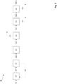
- FIG 1 shows a greatly simplified block flow diagram of a method or a plant according to the prior art, such as in FIG U.S. 2015/0321914 disclosed.
- a feed gas stream FG is introduced into an autothermal reforming unit 100 and converted into a synthesis gas stream SG1.
- Synthesis gas stream SG1 is subsequently introduced into a conversion unit 101, as a result of which carbon monoxide contained in synthesis gas stream SG1 is converted with water vapor to form carbon dioxide and hydrogen.
- Hydrogen-enriched synthesis gas stream SG2 is subsequently introduced into a pressure swing adsorption unit 102 in order to separate hydrogen from the synthesis gas stream SG2 with high purity.
- Hydrogen separated from the pressure swing adsorption unit 102 is discharged from the pressure swing adsorption unit 102 in the form of a hydrogen-rich stream HG1.
- a hydrogen-depleted residual gas stream RG1 is also discharged deducted from the pressure swing adsorption unit 102 and introduced into a separation unit 103.
- carbon dioxide is separated in high purity by a number of compression and cooling steps as well as drying steps and drawn off from the separation unit as a carbon dioxide-rich stream CG1.
- Carbon dioxide-rich stream CG1 still contains significant residual amounts of methane, which can optionally be removed by distillation of the carbon dioxide-rich stream CG1 (not shown).
- the resulting pure carbon dioxide product is suitable for carbon dioxide sequestration or for further use, for example the synthesis of methanol by reaction with hydrogen produced from electrolysis electricity.
- a residual gas stream RG2 that is greatly depleted in carbon dioxide is also drawn off from the separating unit 103 and introduced into a membrane unit 104 .
- a hydrogen-rich stream HG2 which is enriched with hydrogen compared to the residual gas stream RG2 is produced in the membrane unit 104 by membrane separation and drawn off from the membrane unit 104 .
- a residual gas flow RG3 depleted in hydrogen compared to the residual gas flow RG2 is generated and drawn off from the membrane unit 104 .
- Hydrogen-rich stream HG2 can optionally either be recycled to the pressure adsorption unit 102 to increase the hydrogen yield or used as fuel gas in the autothermal reforming unit 100 for further use.
- Table 1 below shows a material balance of a simulation of a method according to figure 1 .
- the simulation was carried out using the "Aspen Plus" software.
- the composition of the feed gas stream is given without the addition of steam.
- the specific carbon dioxide emission of the method according to the method of figure 1 with the material balance according to Table 1 is 0.140 kg CO 2 per standard cubic meter (Nm 3 ) of hydrogen produced.
- the autothermal reforming unit 100 can also, as also in the U.S. 2015/0321914 discloses an endothermic reforming unit can be used.
- the endothermic reforming unit can be a steam reformer known to those skilled in the art. If a steam reformer is used, the specific carbon dioxide emission of 0.396 kg CO 2 per standard cubic meter of hydrogen produced is several times higher than when using an autothermal reformer.
- FIG 2 shows a highly simplified block flow diagram of a method or a plant according to a first example of the invention (example 1) with a parallel arrangement of the reforming units.
- a feed gas stream FG is divided into two partial streams.
- a first substream of the feed gas stream FG is introduced into an endothermic reforming unit 200 (first reforming unit configured for an endothermic reforming step).
- a second partial stream of the feed gas stream FG is introduced into an autothermal reforming unit 201 (second reforming unit configured for an autothermal reforming step).
- the first partial flow of the Feed gas stream FG converted into a synthesis gas stream SG 1.
- the second partial flow of the feed gas flow FG is converted into a synthesis gas flow SG2.
- the heat generated in the autothermal reforming step of the autothermal reforming unit 201 is used for heating in the endothermic reforming step of the endothermic reforming unit 200, indicated by the heat flow 202.
- the second synthesis gas stream SG2 is used directly for heating in the endothermic reforming step of the endothermic reforming unit 200, i.e. the im Heat contained in the second synthesis gas stream SG2 is used for heating in the endothermic reforming step of the endothermic reforming unit 201 without being transferred to a further heat transport medium.
- the synthesis gas streams SG1 and SG2 generated by the endothermic reforming unit 200 and the autothermal reforming unit 201 are combined to form a mixed synthesis gas stream SG3, which is fed into a conversion unit 203, whereby the carbon monoxide contained in the synthesis gas stream SG3 is converted with water vapor to form carbon dioxide and hydrogen.
- Hydrogen-enriched synthesis gas stream SG4 is subsequently introduced into a pressure swing adsorption unit 204 in order to separate hydrogen from the synthesis gas stream SG4 with high purity. Hydrogen separated from the pressure swing adsorption unit 204 is discharged from the pressure swing adsorption unit 204 in the form of a hydrogen-rich stream HG1.
- a hydrogen-depleted first residual gas stream RG1 is drawn off from the pressure swing adsorption unit 204 and introduced into a separation unit 205 .
- carbon dioxide is separated in high purity by a plurality of compression and cooling steps as well as drying steps and drawn off from the separation unit 205 as a carbon dioxide-rich stream CG1.
- Carbon dioxide-rich stream CG1 still contains significant residual amounts of methane, which can optionally be removed by distillation of the carbon dioxide-rich stream CG1 (not shown).
- the resulting pure carbon dioxide product is suitable for sequestration of the carbon dioxide or for further use, for example the synthesis of methanol by reaction with hydrogen produced from electrolysis.
- a residual gas flow RG2 greatly depleted in carbon dioxide is also drawn off from the separating unit 205 and introduced into a membrane unit 206 .
- a hydrogen-rich stream HG2 that is enriched with hydrogen compared to the residual gas stream RG2 is produced in the membrane unit 206 and drawn off from the membrane unit 206 .
- a residual gas flow RG3 that is depleted in hydrogen compared to the residual gas flow RG2 is generated and drawn off from the membrane unit 206 .
- the hydrogen-rich stream HG2 can optionally either be recycled to the pressure adsorption unit 204 to increase the overall hydrogen yield of the process for further use or used as fuel gas in the autothermal reforming unit 201.
- Table 2 shows a material balance based on a simulation of the first example of a method according to the invention figure 2 .
- the simulation was carried out using the "Aspen Plus" software.
- the composition of the feed gas stream is given without the addition of steam.
- ⁇ b>Table 2 Material balance example 1 ⁇ /b> FG SG3 SG4 HG1 RG1 RG2 CG1 HG2 RG3 temperature °C 40 958 40 40 40 40 40 40 40 40 40 40 print bar 51 47 42 41 2 20 20 40 5 mass flow kmol/h 3252 15139 12476 8923 5400 2671 2729 1847 824 CO2 mol % 0.77 6.07 22.93 0.00 64.40 28.32 99.71 33.36 17.01 CO mol % 0.00 13.96 0.88 0.00 2.70 5.46 0.00 1.93 13:36 H2 mol % 0.00 47.34 72:13 99.99 22.53 45.54 0.00 61.74 9:24 N2 mol % 0.54 0.12
- figure 3 shows a greatly simplified block flow diagram of a method or a plant according to a second example of the invention (example 2).
- the process or system according to figure 3 differs according to the process or the installation figure 2 through the serial arrangement or interconnection of the reforming units.
- the endothermic reforming unit 200 (first reforming unit configured for an endothermic reforming step) is arranged upstream in the gas flow direction to the autothermal reforming unit 201 (second reforming unit configured for an autothermal reforming step), which is arranged correspondingly downstream in the gas flow direction to the endothermic reforming unit 200 is.
- a feed gas stream FG is introduced into an endothermic reforming unit 200 and converted into a synthesis gas stream SG1.
- the synthesis gas stream SG1 is converted into a synthesis gas stream SG3 in the autothermal reforming unit 201 .
- the heat generated in the autothermal reforming step of autothermal reforming unit 201 is used for heating in the endothermic reforming step of endothermic reforming unit 200, indicated by heat flow 202.
- syngas stream SG3 is used directly for heating in the endothermic reforming step of endothermic reforming unit 200, i.e. that in syngas stream SG3 Heat contained is used for heating in the endothermic reforming step of the endothermic reforming unit 200 without further transmission to a heat transport medium. All the following process steps correspond to example 1 according to figure 2 .
- Table 3 shows a material balance of a simulation of the second example of a method according to the invention figure 3 .
- the simulation was carried out using the "Aspen Plus" software.
- the composition of the feed gas stream is given without the addition of steam.
- ⁇ b>Table 3 Material balance example 2 ⁇ /b> FG SG3 SG4 HG1 RG1 RG2 CG1 HG2 RG3 temperature °C 40 975 40 40 40 40 40 40 40 40 40 40 40 print bar 51 44 39 39 2 20 20 40 5 mass flow kmol/h 2540 15037 11714 8923 4281 4281 2242 1491 549 CO2 mol % 0.77 5.02 20.09 0.00 66.80 66.80 99.82 34.01 21.01 CO mol % 0.00 11.40 0.66 0.00 2.39 2.39 0.00 1.68 14.08 H2 mol % 0.00 49.59 76.71 100.0 23:16 23:16 0.00 62.35 11:31 N2 mol % 0.54
- the specific carbon dioxide emission according to the method figure 3 with the material balance according to Table 3 is 0.118 kg CO 2 per standard cubic meter (Nm 3 ) of hydrogen produced. Compared to the comparative example, this corresponds to a reduction in the specific carbon dioxide emission of 15%. Furthermore, the serial arrangement of the reforming units 200 and 201 results in an advantage with regard to the reduction of the specific carbon dioxide emission compared to the parallel arrangement of the reforming units 200 and 201 according to FIG figure 2 .
Landscapes
- Chemical & Material Sciences (AREA)
- Organic Chemistry (AREA)
- Chemical Kinetics & Catalysis (AREA)
- Engineering & Computer Science (AREA)
- Inorganic Chemistry (AREA)
- Combustion & Propulsion (AREA)
- Health & Medical Sciences (AREA)
- General Health & Medical Sciences (AREA)
- Analytical Chemistry (AREA)
- General Chemical & Material Sciences (AREA)
- Oil, Petroleum & Natural Gas (AREA)
- Physics & Mathematics (AREA)
- Mechanical Engineering (AREA)
- Thermal Sciences (AREA)
- General Engineering & Computer Science (AREA)
- Hydrogen, Water And Hydrids (AREA)
Abstract
Description
- Die Erfindung betrifft ein Verfahren zur Herstellung von Wasserstoff durch Reformieren von Kohlenwasserstoffen mit Dampf und zur Abscheidung von Kohlendioxid. Die Erfindung betrifft ferner eine Anlage zur Herstellung von Wasserstoff durch Reformieren von Kohlenwasserstoffen mit Dampf und zur Abscheidung von Kohlendioxid.
- Die global produzierte Wasserstoffmenge wird heute auf 70 Mt pro Jahr geschätzt, wobei der größte Teil davon durch endotherme Reformierung von Erdgas mit Dampf an einem Reformierungskatalysator auf Nickelbasis erzeugt wird. Bei diesem als Dampfreformierung (steam methane reforming - SMR) bezeichneten Prozess reagiert hauptsächlich Methan und Wasserdampf zu einem Gemisch aus hauptsächlich Wasserstoff, Kohlenmonoxid und Kohlendioxid. Der Dampfreformierungsprozess weist einen großen Kohlendioxidfußabdruck auf, da für jede Tonne produzierten Wasserstoffs circa 9 Tonnen Kohlendioxid emittiert werden. Berechnungen zufolge trägt die Dampfreformierung von Erdgas alleine mit einem Anteil von 1,5 % zu den global verursachten Kohlendioxidemissionen bei (Wisman et al., Science 364, 756-759, 2019).
- Wasserstoff wird auch durch autotherme Reformierung (autothermal reforming - ATR) von Erdgas hergestellt. Von der Dampfreformierung unterscheidet sich die autotherme Reformierung dadurch, dass dem endothermen Reformierungsschritt ein exothermer partieller Oxidationsschritt vorangeht, welcher die für den nachfolgenden endothermen, katalytischen Schritt nötige Reaktionswärme liefert. Für die partielle Oxidation wird in der Regel Luft oder Sauerstoff, beispielsweise aus einer Luftzerlegungsanlage, als Oxidationsmedium verwendet. Ferner erfordert die ATR einen Brenner, welcher mit Hilfe eines Brenngases die erforderliche Aktivierungsenergie für die partielle Oxidation zur Verfügung stellt. Das Resultat dieser beiden Reaktionsschritte, der partiellen Oxidation von Methan und der anschließenden endothermen katalytischen Reformierung des Zwischenprodukts mit Dampf, ist ebenfalls ein hauptsächlich Wasserstoff, Kohlenmonoxid und Kohlendioxid aufweisendes Synthesegas.
- Um die genannten Prozesse umweltfreundlicher zu gestalten, wurden in der Vergangenheit Verfahren entwickelt, um das bei der SMR oder ATR erzeugte Kohlendioxid als möglichst reines Kohlendioxidprodukt aus dem primär erzeugten Synthesegasgemisch abzutrennen. Dafür stehen Gaswäscheverfahren auf Basis von physikalischer oder chemischer Absorption in Absorptionsmitteln wie Methanol oder Aminen, sowie die tiefkalte flüssige Abscheidung und Reinigung des Kohlendioxids durch Kompression, Kondensation und Destillation zur Verfügung. Das in großen Mengen in Absorptionsmitteln absorbierte und anschließend wieder desorbierte oder bei niedrigen Temperaturen durch Kondensation abgeschiedene Kohlendioxid kann jedoch häufig keiner sinnvollen weiteren industriellen Verwendung zugeführt werden. Häufig bleibt daher nur die Möglichkeit, das nicht verwendbare Kohlendioxid langfristig zu speichern, um es nicht in die Atmosphäre gelangen zu lassen. Die Kombination aus Abscheidung (durch Gaswäsche oder Kondensation) und Speicherung von Kohlendioxid wird auch als Sequestrierung oder CCS (carbon capture and storage) bezeichnet.
- Es ist daher erforderlich bekannte Prozesse zur Herstellung von Wasserstoff dergestalt zu verbessern, dass von vorneherein geringere Mengen an Kohlendioxid pro Tonne produzierten Wasserstoffs generiert werden.
-
US 2015/0321914 A1 offenbart ein Verfahren, in dem ein primär durch Dampfreformierung oder autotherme Reformierung erzeugtes Synthesegas durch Konvertierung des im primär erzeugten Synthesegas enthaltenen Kohlenmonoxid mit Dampf zu Kohlendioxid und Wasserstoff umgesetzt wird (Wassergas-Shift-Reaktion). Aus dem mit Kohlendioxid und Wasserstoff angereicherten konvertierten Synthesegas wird anschließend mit Hilfe einer Druckwechseladsorptionseinheit Wasserstoff abgetrennt. Das an Wasserstoff verarmte, jedoch noch kohlendioxidreiche Restgas wird anschließend in einer als kryogene Reinigungseinheit (cryogenic purification unit - CPU) bezeichneten Vorrichtung behandelt, um Kohlendioxid in möglichst reiner Form aus dem Restgas abzuscheiden und zu verflüssigen. Das verflüssigte Kohlendioxid kann anschließend einer Lagerung zugeführt oder für Industrie- oder Verbrauchszwecke verwendet werden. - Allgemein ist es eine Aufgabe der vorliegenden Erfindung, die vorgenannten Nachteile des Standes der Technik zu überwinden.
- Insbesondere besteht eine Aufgabe der vorliegenden Erfindung darin, bekannte Verfahren so zu modifizieren, dass die pro Gewichtseinheit produzierten Wasserstoffs gebildete Menge Kohlendioxid reduziert wird.
- Insbesondere besteht eine Aufgabe der vorliegenden Erfindung darin, die Kohlendioxidemissionen von Verfahren zu reduzieren, welche autotherme Reformierung von Methan mit tiefkalter Kohlendioxidabscheidung kombinieren.
- Ein Beitrag zur mindestens teilweisen Erfüllung mindestens einer der obigen Aufgaben wird durch die unabhängigen Ansprüche geleistet. Die abhängigen Ansprüche stellen bevorzugte Ausführungsformen bereit, die zur mindestens teilweisen Erfüllung mindestens einer der Aufgaben beitragen. Bevorzugte Ausgestaltungen von Bestandteilen einer erfindungsgemäßen Kategorie sind, soweit zutreffend, ebenso bevorzugt für gleichnamige oder entsprechende Bestandteile einer jeweils anderen erfindungsgemäßen Kategorie.
- Die Ausdrücke "aufweisend", "umfassend" oder "beinhaltend" etc. schließen nicht aus, dass weitere Elemente, Inhaltsstoffe etc. enthalten sein können. Der unbestimmte Artikel "ein" schließt nicht aus, dass eine Mehrzahl vorhanden sein kann.
- Die Aufgaben der Erfindung werden zumindest teilweise gelöst durch ein Verfahren zur Herstellung von Wasserstoff durch Reformieren von Kohlenwasserstoffen mit Dampf, sowie zur Abscheidung von Kohlendioxid, wobei das Verfahren die folgenden Schritte umfasst:
- (a) Bereitstellen eines Einsatzgasstroms FG, wobei der Einsatzgasstrom FG eine Kohlenwasserstoffkomponente und Dampf umfasst, wobei die Kohlenwasserstoffkomponente zumindest Methan umfasst;
- (b) Reformieren zumindest eines Teils des Einsatzgasstroms FG in einem endothermen Reformierungsschritt an einem Reformierungskatalysator zu einem Synthesegasstrom SG1, wobei der Synthesegasstrom SG1 Wasserstoff, Kohlenmonoxid, Kohlendioxid, sowie nicht reagiertes Methan enthält;
- (c) Reformieren eines Teils des Einsatzgasstroms FG in einem autothermen Reformierungsschritt zu einem Synthesegasstrom SG2 und Zusammenführen der Synthesegasströme SG1 und SG2 zu einem Synthesegasstrom SG3, oder Reformieren des Synthesegasstroms SG1 in einem autothermen Reformierungsschritt zu einem Synthesegasstrom SG3,
wobei der autotherme Reformierungsschritt exotherme partielle Oxidation umfasst und endotherme Reformierung mit Dampf an einem Reformierungskatalysator umfasst, wobei
die Synthesegasströme SG2 und SG3 Wasserstoff, Kohlenmonoxid, Kohlendioxid, sowie nicht reagiertes Methan enthalten, und wobei durch den autothermen Reformierungsschritt erzeugte Wärme zum Heizen im endothermen Reformierungsschritt gemäß Schritt (b) genutzt wird; - (d) Konvertieren des im Synthesegasstrom SG3 enthaltenen Kohlenmonoxid mit Dampf zu Wasserstoff und Kohlendioxid zu einem Synthesegasstrom SG4, wobei der Synthesegasstrom SG4 Wasserstoff, Kohlendioxid, nicht reagiertes Methan sowie in Schritt (d) nicht konvertiertes Kohlenmonoxid enthält;
- (e) Abtrennen von Wasserstoff aus dem Synthesegasstrom SG4 durch Druckwechseladsorption, wobei ein wasserstoffreicher Strom HG1 sowie ein Restgasstrom RG1 erhalten werden, wobei der Restgasstrom RG1 Kohlendioxid, in Schritt (d) nicht konvertiertes Kohlenmonoxid, in Schritt (e) nicht abgetrennten Wasserstoff sowie nicht reagiertes Methan enthält;
- (f) Abtrennen von Kohlendioxid aus dem in Schritt (e) erzeugten Restgasstrom RG1 durch tiefkalte Kohlendioxid-Abscheidung, wobei ein kohlendioxidreicher Strom CG1 sowie ein Restgasstrom RG2 erhalten werden, wobei der Restgasstrom RG2 in Schritt (d) nicht konvertiertes Kohlenmonoxid, in Schritt (e) nicht abgetrennten Wasserstoff, in Schritt (f) nicht abgetrenntes Kohlendioxid sowie nicht reagiertes Methan enthält.
- Gegenüber aus dem Stand der Technik bekannten Verfahren zeichnet sich das erfindungsgemäße Verfahren dadurch aus, dass gemäß den Schritten (b) und (c) eine Kombination aus endothermem und autothermem Reformierungsschritt zum Einsatz kommt, und durch den autothermen Reformierungsschritt erzeugte Wärme zum Heizen im endothermen Reformierungsschritt gemäß Schritt (b) genutzt wird. Der autotherme Reformierungsschritt wird in einer autothermen Reformerierungseinheit (autothermer Reformer) durchgeführt. Der endotherme Reformierungsschritt wird in einer endothermen Reformierungseinheit durchgeführt (endothermer Reformer, beispielsweise Dampfreformer). Dadurch werden die spezifischen Kohlendioxidemissionen im Hinblick auf den Gesamtprozess überraschenderweise signifikant gesenkt. Unter "spezifischen Kohlendioxidemissionen" wird die Masse an gebildetem CO2 verstanden, die pro Normkubikmeter produziertem Wasserstoff über den Gesamtprozess gebildet wird. Die spezifischen Kohlendioxidemissionen können beispielsweise in kg CO2 / Nm3 Wasserstoff angegeben werden.
- Im endothermen Reformierungsschritt gemäß Schritt (b) wird das Einsatzgas FG durch Zufuhr von Wärme an einem geeigneten Katalysator zum Synthesegas SG1 umgesetzt. Bei dem Katalysator handelt es sich beispielsweise um einen dem Fachmann bekannten Nickel-Katalysator. Die für den endothermen Reformierungsschritt zum Ablauf der Reformierungsreaktion erforderliche Wärme wird zumindest teilweise, vorzugsweise vollständig durch im autothermen Reformierungsschritt gebildete Wärme geliefert. Je nach Anordnung der Reformierungseinheiten wird das Einsatzgas FG teilweise oder vollständig in die Reformierungseinheit des endothermen Reformierungsschritts eingeschleust und zum Synthesegas SG1 umgesetzt.
- Der autotherme Reformierungsschritt gemäß Schritt (c) umfasst einen Schritt einer partiellen Oxidation des Einsatzgasstroms FG und einen nachfolgenden endothermen Reformierungsschritt mit Dampf zur Umsetzung des Einsatzgasstroms FG zum Synthesegasstrom SG2 oder zum Synthesegasstrom SG3. Der Schritt der partiellen Oxidation des autothermen Reformierungsschritts erfordert die Zufuhr eines Oxidationsmittels wie Luft, reinen Sauerstoff oder mit Sauerstoff angereicherter Luft. Das Oxidationsmittel wird üblicherweise über einen Brenner in den autothermen Reformer eingeschleust. Die partielle Oxidation des Einsatzgasstroms FG zum Synthesegasstrom SG2 oder zum Synthesegasstrom SG3 im Rahmen des autothermen Reformierungsschritts ist eine exotherme Reaktion. Die dadurch erzeugte Abwärme wird für den "endothermen Teil" des autothermen Reformierungsschritts genutzt. Der autotherme Reformierungsschritt ist so ausgelegt, dass in Summe, über beide Reaktionsstufen (partielle Oxidation und endotherme Reformierung) genügend Wärme erzeugt wird, welche zum Beheizen des endothermen Reformierungsschritts zur Umsetzung des Einsatzgases FG zum Synthesegas SG1 nutzbar ist.
- Das erfindungsgemäße Verfahren beinhaltet zwei durch Schritt (c) definierte Alternativen.
- Gemäß der ersten Alternative wird ein Teil des Einsatzgasstroms FG im endothermen Reformierungsschritt zum Synthesegasstrom SG1 reformiert. Ein weiterer Teil des Einsatzgasstroms FG, vorzugsweise der verbleibende Teil des Einsatzgasstroms FG, wird im autothermen Reformierungsschritt zum Synthesegasstrom SG2 reformiert. Die Synthesegasströme SG2 und SG3 werden anschließend zu einem Synthesegasstrom SG3 kombiniert. Daraus ergibt sich eine parallele Anordnung oder Verschaltung der Reformierungseinheiten für den endothermen Reformierungsschritt und für den autothermen Reformierungsschritt.
- Gemäß der zweiten Alternative des erfindungsgemäßen Verfahrens wird das Einsatzgas FG vollständig in die Reformierungseinheit des endothermen Reformierungsschritt eingeschleust und zum Synthesegasstrom SG1 umgesetzt. Dabei wird das Einsatzgas FG nur teilweise zum Synthesegas SG1 umgesetzt, das heißt es verbleibt ein vergleichsweise hoher Anteil an Methan und gegebenenfalls anderen reformierbaren Kohlenwasserstoffkomponenten im Synthesegas SG1. Diese verbleibende Menge wird anschließend im autothermen Reformierungsschritt zum Synthesegas SG3 reformiert. Daraus ergibt sich eine serielle Anordnung oder Verschaltung der Reformierungseinheiten für den endothermen Reformierungsschritt und für den autothermen Reformierungsschritt, wobei der autotherme Reformierungsschritt auf den endothermen Reformierungsschritt folgt. Mit anderen Worten, die Reformierungseinheit für den autothermen Reformierungsschritt ist in Gasflussrichtung stromabwärts zur Reformierungseinheit für den endothermen Reformierungsschritt angeordnet.
- Vorzugsweise wird der im autothermen Reformierungschritt erzeugte Synthesegasstrom, das heißt der Synthesegasstrom SG2 bei paralleler Anordnung der Reformierungseinheiten oder der Synthesegasstrom SG3 bei serieller Anordnung der Reformierungseinheiten, direkt für die Übertragung von Wärme im endothermen Reformierungsschritt genutzt. Der Synthesegasstrom SG2 und/oder der Synthesegasstrom SG3 weisen dabei vorzugsweise eine Temperatur von 750 bis 1100 °C auf.
- Der Einsatzgasstrom FG weist zumindest eine Kohlenwasserstoffkomponente auf, die mit Wasserdampf, zu einem Synthesegas SG1, SG2, SG3 oder SG4 reformierbar ist. Das Synthesegas weist zumindest Wasserstoff, Kohlenmonoxid und Kohlendioxid als Produktkomponenten auf. Der Einsatzgasstrom FG weist zumindest Methan als Kohlenwasserstoffkomponente auf. Weitere höhere analoge Kohlenwasserstoffe wie beispielsweise Ethan, Propan oder Butan können im Einsatzgasstrom FG vorhanden sein.
- Ein Einsatzgas kann zunächst in einem sogenannten Vorreformer behandelt werden, um höhere Kohlenwasserstoffe mit Dampf zu kurzkettigen Kohlenwasserstoffen umzuwandeln, insbesondere mit dem Zweck den Methan-Anteil im Einsatzgasstrom FG zu erhöhen. Der Zweck des Vorreformers besteht somit allgemein darin, Kohlenwasserstoffe mit mindestens zwei Kohlenstoffatomen in Kohlenmonoxid, Wasserstoff und Methan umzuwandeln. Ein in einem Vorreformer behandelter Einsatzgasstrom FG kann somit bereits bestimmte Mengen an Kohlenmonoxid und Wasserstoff enthalten.
- Der durch die Kombination aus autothermem und endothermem Reformierungsschritt gebildete Synthesegasstrom SG3 wird einem Konvertierungsschritt (d) zugeführt. In diesem Konvertierungsschritt wird im Synthesegasstrom SG3 enthaltenes Kohlenmonoxid mit Wasser durch die sogenannte Wassergas-Shift-Reaktion an einem geeigneten Katalysator zu Wasserstoff und Kohlendioxid umgesetzt. Vor Einschleusen in Schritt (d) wird das Synthesegas SG3 abgekühlt. Davon abhängig ob es sich gemäß Schritt (d) um eine sogenannte Niedrigtemperatur-Shift oder eine Hochtemperatur-Shift handelt, wird das Synthesegas SG3 vor Einschleusen in Schritt (d) mehr oder weniger stark abgekühlt.
- Der durch den Konvertierungsschritt (d) gebildete Synthesegasstrom SG4 ist mit Wasserstoff und Kohlendioxid angereichert und an Kohlenmonoxid verarmt. Synthesegasstrom SG4 wird nachfolgend einem Trennschritt (e) unterzogen, in dem weitgehend reiner Wasserstoff aus dem Synthesegasstrom SG4 durch Druckwechseladsorption (pressure swing adsorption, PSA) erzeugt wird. Der durch die Druckwechseladsorption erhaltene wasserstoffreiche Strom HG1 weist regelmäßig einen Wasserstoffgehalt von mindestens 95 mol-%, vorzugsweise von mindestens 99 mol-%, weiter bevorzugt von mindestens 99,5 mol-% und weiter bevorzugt von mindestens 99,9 mol-% auf. Das an Wasserstoff verarmte Nebenprodukt des Druckwechseladsorptionsschritts, der Restgasstrom RG1, ist im Vergleich zum Synthesegasstrom SG4 stark an Wasserstoff verarmt und stark mit Kohlendioxid angereichert. Es enthält ferner nicht in Schritt (d) konvertiertes Kohlenmonoxid und nicht in den Schritten (b) und (c) konvertiertes Methan. Durch das Vorhandensein von Gasen mit hohem Heizwert (Methan, Kohlenmonoxid und Wasserstoff) kann es verfahrensintern oder -extern als Brennstoff verwendet werden.
- Zur Abtrennung von Kohlendioxid aus dem Restgasstrom RG1 wird dieser einer tiefkalten Kohlendioxid-Abscheidung gemäß Schritt (f) unterzogen, wodurch ein kohlendioxidreicher Strom CG1 sowie ein weiterer Restgasstrom RG2 erhalten werden. Der Trennschritt (f) erfordert die teilweise Kondensation des im Restgasstrom RG1 enthaltenen Kohlendioxid, und zur Erzielung einer bestimmten Reinheit nachfolgend und optional die Destillation des kohlendioxidreichen Stroms CG1. Die tiefkalte Kohlendioxid-Abscheidung wird vorzugsweise bei einer Temperatur von weniger als 35 °C durchgeführt, oder weniger als 20 °C, oder weniger als 0 °C, oder weniger als - 20 °C, oder weniger als - 40 °C, oder weniger als - 50 °C, oder weniger als - 55 °C. Die tiefkalte Kohlendioxid-Abscheidung wird ferner vorzugsweise bei einer Temperatur von mehr als - 60 °C durchgeführt.
- Der Synthesegasstrom SG1 kann auch als erster Synthesegasstrom bezeichnet werden, der Synthesegasstrom SG2 als zweiter Synthesegasstrom und so weiter. Dies trifft mutatis mutandis auf alle weiteren im Rahmen dieser Offenbarung nummerierten Fluidströme RG, CG und HG zu.
- Eine bevorzugte Ausführungsform des erfindungsgemäßen Verfahrens ist dadurch gekennzeichnet, dass aus dem Restgasstrom RG2 Wasserstoff abgetrennt wird, wobei ein wasserstoffreicher Strom HG2 und ein Restgasstrom RG3 erhalten werden. Der Restgasstrom RG2 weist regelmäßig, trotz des vorangegangenen Trennschritts durch Druckwechseladsorption, größere Mengen an Restwasserstoff von bis zu 50 mol-% auf. Es ist daher vorteilhaft, den Restgasstrom 2 einem weiteren Trennschritt zur Abtrennung oder zumindest Anreicherung von Wasserstoff zuzuführen. Vorzugsweise wird der Wasserstoff aus dem Restgasstrom RG2 durch Membrantrennung abgetrennt.
- In einem Beispiel des erfindungsgemäßen Verfahrens wird der wasserstoffreiche Strom HG2 dem Synthesegasstrom SG4 zum Abtrennen von Wasserstoff durch Druckwechseladsorption gemäß Schritt (e) zugeführt. Insbesondere Membrantrennverfahren weisen keine ausreichende Selektivität auf, um aus dem Restgasstrom RG2 einen Wasserstoffstrom mit hoher Reinheit, beispielsweise von mehr als 99 mol-%, zu gewinnen. Da ein zweiter Druckwechseladsorptionsschritt im Sinne einer zweiten Druckwechseladsorptionsvorrichtung zu aufwändig und teuer wäre, wird der wasserstoffreiche Strom HG2 in vorteilhafter Weise Schritt (e) zugeführt, wodurch die Wasserstoff-Ausbeute bezogen auf den Gesamtprozess erhöht wird.
- Alternativ werden im wasserstoffreichen Strom HG2 enthaltene Gase als Brenngase zum Heizen im autothermen Reformierungsschritt gemäß Schritt c) genutzt. Für den autothermen Reformierungsschritt muss das Einsatzgas FG angewärmt werden, was beispielsweise mittels einer befeuerten Heizeinheit erfolgen kann. Die befeuerte Heizeinheit kann zumindest teilweise mit Hilfe der im wasserstoffreichen Strom HG2 enthaltenen Gase, welche einen hohen Heizwert aufweisen, insbesondere Kohlenmonoxid, Methan und Wasserstoff beheizt werden, um die Wärmeintegration des Prozesses zu verbessern.
- Eine bevorzugte Ausführungsform des erfindungsgemäßen Verfahrens ist dadurch gekennzeichnet, dass der kohlendioxidreiche Strom CG1 nicht reagiertes Methan umfasst, und der kohlendioxidreiche Strom CG1 einem thermischen Trennverfahren zur Abtrennung von Methan unterzogen wird, wobei ein kohlendioxidreicher Strom CG2 erhalten wird. Der kohlendioxidreiche Strom kann als Ergebnis der tiefkalten Kohlendioxidabscheidung signifikante Mengen Methan enthalten, beispielsweise bis zu 0,2 mol-% Methan, oder bis zu 0,5 mol-% Methan. Durch einen weiteren Schritt, welcher ein thermisches Trennverfahren beinhaltet, kann der Kohlendioxidgehalt des kohlendioxidreichen Stroms CG1 weiter erhöht werden. Bei dem thermischen Trennverfahren handelt es sich vorzugsweise um eine Destillation. Dadurch kann ein weitgehend reines Kohlendioxidprodukt erhalten werden, welches einfacher einer ökologisch sinnvollen Valorisierung zugeführt werden kann als ein mit Methan verunreinigtes Kohlendioxidprodukt. So kann reines Kohlendioxid beispielsweise mit Elektrolyse-Wasserstoff im richtigen Verhältnis gemischt als Synthesegas zur Methanol-Produktion eingesetzt werden. Auch bei der Sequestrierung des Kohlendioxids hat ein reines Kohlendioxidprodukt Vorteile, da insbesondere mit Methan verunreinigtes Kohlendioxid bei unbeabsichtigter Freisetzung nach Sequestrierung den Treibhauseffekt bekanntermaßen verstärken würde.
- Eine bevorzugte Ausführungsform des erfindungsgemäßen Verfahrens ist dadurch gekennzeichnet, dass aus dem Restgasstrom RG3 Kohlendioxid abgetrennt wird, wobei ein kohlendioxidreicher Strom CG3 und ein Restgasstrom RG4 erhalten werden. Vorzugsweise wird das Kohlendioxid aus dem Restgasstrom RG3 durch Membrantrennung abgetrennt, um den kohlendioxidreichen Strom CG3 und den Restgasstrom RG4 zu erhalten.
- In einem Beispiel des erfindungsgemäßen Verfahrens werden im Restgasstrom RG4 enthaltene Gase als Brenngase zum Heizen im autothermen Reformierungsschritt gemäß Schritt c) genutzt.
- Der kohlendioxidreiche Strom CG3 wird vorzugsweise dem Restgasstrom RG1 zur tiefkalten Kohlendioxid-Abscheidung gemäß Schritt (f) zugeführt. Dadurch wird die Ausbeute an verwertbarem Kohlendioxid gesteigert und die Menge an tatsächlich emittiertem Kohlendioxid auf ein Minimum reduziert.
- Eine bevorzugte Ausführungsform des erfindungsgemäßen Verfahrens ist dadurch gekennzeichnet, dass der Restgasstrom RG1 zur tiefkalten Kohlendioxid-Abscheidung gemäß Schritt (f) zumindest einem Verdichtungsschritt sowie zumindest einem Abkühlschritt unterzogen wird, wobei der kohlendioxidreiche Strom CG1 zumindest teilweise als kondensierter Kohlendioxidstrom erhalten wird. Die tiefkalte Kohlendioxid-Abscheidung wird vorzugsweise unter Druck durch Kompression durchgeführt, beispielsweise einem Druck zwischen 5 und 74 bar, wobei Restgasstrom RG1 gleichzeitig vorzugsweise auf eine Temperatur oberhalb des Tripelpunkt des Kohlendioxid (minus 56 °C) oder eine andere für die Kondensation geeignete Temperatur abgekühlt wird. Unter diesen Temperatur- und Druckbedingungen kondensiert das Kohlendioxid teilweise aus, wobei die Flüssigphase mit Kohlendioxid angereichert wird und die Gasphase mit nicht kondensierbaren Gasen angereichert wird. Vorzugsweise und soweit erforderlich beinhaltet Schritt (f) mehrere Verdichtungsschritte und/oder mehrere Abkühlschritte, das heißt die Kondensation von Kohlendioxid aus dem Restgasstrom RG1 erfolgt in mehreren hintereinandergeschalteten Kompressions- und Abkühlschritten.
- Vorzugsweise und soweit erforderlich wird der Restgasstrom RG1 im Rahmen von Schritt (f) in einem oder mehreren Schritten getrocknet. Ein Trocknungsschritt kann vor einem Kompressionsschritt, zwischen zwei Kompressionsschritten und/oder nach einem Kompressionsschritt durchgeführt werden. Ein Trocknungsschritt kann ferner vor einem Abkühlschritt, zwischen zwei Abkühlschritten und/oder nach einem Abkühlschritt durchgeführt werden.
- Vorzugsweise und soweit erforderlich wird der Restgasstrom RG1 im Rahmen von Schritt (f) zur Entfernung kondensierbarer Bestandteile wie Methanol einem oder mehreren Abscheideschritten unterzogen. Ein Abscheideschritt kann vor einem Kompressionsschritt, zwischen zwei Kompressionsschritten und/oder nach einem Kompressionsschritt durchgeführt werden. Ein Abscheideschritt kann ferner vor einem Abkühlschritt, zwischen zwei Abkühlschritten und/oder nach einem Abkühlschritt durchgeführt werden.
- Die Aufgaben der Erfindung werden ferner zumindest teilweise gelöst durch eine Anlage, wobei die Anlage zur Durchführung des erfindungsgemäßen Verfahrens konfiguriert ist.
- Die Aufgaben der Erfindung werden ferner zumindest teilweise gelöst durch eine Anlage zur Herstellung von Wasserstoff durch Reformieren von Kohlenwasserstoffen mit Dampf, sowie zur Abscheidung von Kohlendioxid, wobei die Anlage folgende miteinander in Fluidverbindung stehende Anlagenkomponenten umfasst:
- (a) Mittel zum Bereitstellen eines Einsatzgasstroms FG, wobei der Einsatzgasstrom FG eine Kohlenwasserstoffkomponente und Dampf umfasst, wobei die Kohlenwasserstoffkomponente zumindest Methan umfasst;
- (b) eine erste Reformierungseinheit, wobei die erste Reformierungseinheit zum Reformieren zumindest eines Teils des Einsatzgasstroms FG in einem endothermen Reformierungsschritt an einem Reformierungskatalysator konfiguriert ist, wobei in dem endothermen Reformierungsschritt ein Synthesegasstrom SG1 erhältlich ist, wobei der Synthesegasstrom SG1 Wasserstoff, Kohlenmonoxid, Kohlendioxid, sowie nicht reagiertes Methan enthält;
- (c) eine zweite Reformierungseinheit, angeordnet parallel oder stromabwärts zur ersten Reformierungseinheit, wobei
- die zweite Reformierungseinheit bei paralleler Anordnung zur ersten Reformierungseinheit zum Reformieren eines Teils des Einsatzgasstroms FG in einem autothermen Reformierungsschritt konfiguriert ist, wobei
der autotherme Reformierungsschritt exotherme partielle Oxidation umfasst und endotherme Reformierung mit Dampf an einem Reformierungskatalysator umfasst und
in dem autothermen Reformierungsschritt ein Synthesegasstrom SG2 erhältlich ist, und
die erste und die zweite Reformierungseinheit bei paralleler Anordnung so konfiguriert sind, dass die Synthesegasströme SG1 und SG2 zu einem Synthesegasstrom SG3 zusammenführbar sind, - die zweite Reformierungseinheit bei Anordnung stromabwärts zur ersten Reformierungseinheit zum Reformieren zumindest eines Teils des Synthesegasstroms SG1 in einem autothermen Reformierungsschritt konfiguriert ist, wobei
der autotherme Reformierungsschritt exotherme partielle Oxidation umfasst und endotherme Reformierung mit Dampf an einem Reformierungskatalysator umfasst, wobei
in dem autothermen Reformierungsschritt ein Synthesegasstrom SG3 erhältlich ist, wobei
die erste Reformierungseinheit (b) und die zweite Reformierungseinheit (c) so konfiguriert sind, dass durch den autothermen Reformierungsschritt in der zweiten Reformierungseinheit (c) erzeugte Wärme
zum Heizen in der ersten Reformierungseinheit (b) nutzbar ist; - die zweite Reformierungseinheit bei paralleler Anordnung zur ersten Reformierungseinheit zum Reformieren eines Teils des Einsatzgasstroms FG in einem autothermen Reformierungsschritt konfiguriert ist, wobei
- (d) eine Konvertiereinheit, angeordnet
- stromabwärts zur ersten und zweiten Reformierungseinheit bei paralleler Anordnung der ersten und der zweiten Reformierungseinheit, oder
- angeordnet stromabwärts zur zweiten Reformierungseinheit bei Anordnung der zweiten Reformierungseinheit stromabwärts zur ersten Reformierungseinheit, wobei
der Synthesegasstrom SG3 Wasserstoff, Kohlendioxid, nicht reagiertes Methan sowie in der Konvertiereinheit nicht konvertiertes Kohlenmonoxid enthält; - (e) eine Druckwechseladsorptionseinheit, angeordnet stromabwärts zur Konvertiereinheit, wobei
die Druckwechseladsorptionseinheit zum Abtrennen von Wasserstoff aus dem Synthesegasstrom SG3 konfiguriert ist, wobei ein wasserstoffreicher Strom HG1 sowie ein Restgasstrom RG1 erhältlich sind, wobei der Restgasstrom RG1 Kohlendioxid, in der Konvertiereinheit nicht konvertiertes Kohlenmonoxid, in der Druckwechseladsorptionseinheit nicht abgetrennten Wasserstoff sowie nicht reagiertes Methan enthält; - (f) eine Abscheideeinheit, angeordnet stromabwärts zur Druckwechseladsorptionseinheit, wobei die Abscheideeinheit zum tiefkalten Abtrennen von Kohlendioxid aus dem in der Druckwechseladsorptionseinheit erzeugten Restgasstrom RG1 konfiguriert ist, wobei ein kohlendioxidreicher Strom CG1 sowie ein Restgasstrom RG2 erhältlich sind, wobei der Restgasstrom RG2 in der Konvertiereinheit nicht konvertiertes Kohlenmonoxid, in der Druckwechseladsorptionseinheit nicht abgetrennten Wasserstoff, in der Abscheideeinheit nicht abgetrenntes Kohlendioxid sowie nicht reagiertes Methan enthält.
- Erfindungsgemäß sind die erste Reformierungseinheit (b) und die zweite Reformierungseinheit (c) so konfiguriert, dass durch den autothermen Reformierungsschritt in der zweiten Reformierungseinheit (c) erzeugte Wärme zum Heizen in der ersten Reformierungseinheit (b) nutzbar ist. Die erste Reformierungseinheit ist für einen endothermen Reformierungsschritt konfiguriert. Die zweite Reformierungseinheit ist für einen autothermen Reformierungsschritt konfiguriert. Vorzugsweise ist die zweite Reformierungseinheit ein autothermer Reformer. Die zweite Reformierungseinheit ist parallel zur ersten Reformierungseinheit angeordnet oder stromabwärts (downstream) zur ersten Reformierungseinheit angeordnet.
- Bei paralleler Anordnung zur ersten Reformierungseinheit wird in der zweiten Reformierungseinheit ein Synthesegasstrom SG2 erzeugt, welcher mit dem Synthesegasstrom SG1 der ersten Reformierungseinheit zusammenführbar ist. Vorzugsweise wird der Synthesegasstrom SG2 unmittelbar zum Heizen in der ersten Reformierungseinheit genutzt, das heißt die im Synthesegasstrom SG2 enthaltene Wärme wird unmittelbar zum Heizen in der ersten Reformierungseinheit genutzt. "Unmittelbar" bedeutet in diesem Zusammenhang, dass die im Synthesegasstrom SG2 enthaltene Wärme nicht auf eine weiteres Wärmetransportmedium übertragen wird. Die in Synthesegasstrom SG2 enthaltene Wärme wird demnach zum Erzeugen des Synthesegasstroms SG1 im endothermen Prozess der ersten Reformierungseinheit genutzt.
- Bei Anordnung stromabwärts zur ersten Reformierungseinheit wird in der zweiten Reformierungseinheit ein Synthesegasstrom SG3 erzeugt. Vorzugsweise wird der Synthesegasstrom SG3 unmittelbar zum Heizen in der ersten Reformierungseinheit genutzt, das heißt die im Synthesegasstrom SG3 enthaltene Wärme wird unmittelbar zum Heizen in der ersten Reformierungseinheit genutzt. "Unmittelbar" bedeutet in diesem Zusammenhang, dass die im Synthesegasstrom SG3 enthaltene Wärme nicht auf ein weiteres Wärmetransportmedium übertragen wird. Die in Synthesegasstrom SG3 enthaltene Wärme wird demnach zum Erzeugen des Synthesegasstroms SG1 im endothermen Prozess der ersten Reformierungseinheit genutzt.
- Die Erfindung wird im Folgenden durch zwei erfindungsgemäße Ausführungsbeispiele sowie ein nicht erfindungsgemäßes Vergleichsbeispiel in Verbindung mit drei Zeichnungen näher erläutert, wobei die Ausführungsbeispiele und die Zeichnungen keine Beschränkung der Erfindung bedeuten.
- Es zeigen
- Figur 1
- ein Blockfließbild eines Verfahrens oder einer Anlage nach dem Stand der Technik,
- Figur 2
- ein Blockfließbild einer ersten Alternative eines erfindungsgemäßen Verfahrens oder einer erfindungsgemäßen Anlage mit paralleler Anordnung der Reformierungseinheiten für den endothermen und den autothermen Reformierungsschritt,
- Figur 3
- ein Blockfließbild einer zweiten Alternative eines erfindungsgemäßen Verfahrens oder einer erfindungsgemäßen Anlage mit serieller Anordnung der Reformierungseinheiten für den endothermen und den autothermen Reformierungsschritt.
-
Figur 1 zeigt ein stark vereinfachtes Blockfließbild eines Verfahrens oder einer Anlage gemäß dem Stand der Technik, wie beispielsweise in derUS 2015/0321914 offenbart. Ein Einsatzgasstrom FG wird in eine autotherme Reformierungseinheit 100 eingeschleust und zu einem Synthesegasstrom SG1 umgesetzt. Synthesegasstrom SG1 wird nachfolgend in eine Konvertiereinheit 101 eingeschleust, wodurch in Synthesegasstrom SG1 enthaltenes Kohlenmonoxid mit Wasserdampf zu Kohlendioxid und Wasserstoff umgesetzt wird. Mit Wasserstoff angereicherter Synthesegasstrom SG2 wird nachfolgend in eine Druckwechseladsorptionseinheit 102 eingeschleust, um Wasserstoff aus dem Synthesegasstrom SG2 mit hoher Reinheit abzutrennen. Aus der Druckwechseladsorptionseinheit 102 abgetrennter Wasserstoff wird in Form eines wasserstoffreichen Stroms HG1 aus der Druckwechseladsorptionseinheit 102 ausgeschleust. Ebenfalls wird ein an Wasserstoff verarmter Restgasstrom RG1 aus der Druckwechseladsorptionseinheit 102 abgezogen und in eine Abscheideeinheit 103 eingeschleust. In der Abscheideeinheit 103 wird Kohlendioxid durch mehrere Kompressions- und Abkühlschritte sowie Trocknungsschritte in hoher Reinheit abgeschieden und als kohlendioxidreicher Strom CG1 aus der Abscheideeinheit abgezogen. Kohlendioxidreicher Strom CG1 enthält noch signifikante Restmengen Methan, die optional durch Destillation des kohlendioxidreichen Stroms CG1 entfernbar sind (nicht gezeigt). Das resultierende reine Kohlendioxidprodukt eignet sich für die Sequestrierung des Kohlendioxids oder für eine Weiterverwendung, beispielsweise die Synthese von Methanol durch Umsetzung mit aus Elektrolysestrom erzeugtem Wasserstoff. Aus der Abscheideeinheit 103 wird auch ein stark an Kohlendioxid verarmter Restgasstrom RG2 abgezogen und in eine Membraneinheit 104 eingeschleust. Durch Membrantrennung wird in Membraneinheit 104 ein gegenüber Restgasstrom RG2 mit Wasserstoff angereicherter wasserstoffreicher Strom HG2 erzeugt und aus der Membraneinheit 104 abgezogen. Ferner wird ein gegenüber Restgasstrom RG2 an Wasserstoff verarmter Restgasstrom RG3 erzeugt und aus der Membraneinheit 104 abgezogen. Wasserstoffreicher Strom HG2 kann zur weiteren Verwendung optional entweder zur Druckadsorptionseinheit 102 zur Steigerung der Wasserstoffausbeute zurückgeführt werden oder als Brenngas in der autothermen Reformierungseinheit 100 verwendet werden. - Die nachfolgende Tabelle 1 zeigt eine Materialbilanz einer Simulation eines Verfahrens gemäß
Figur 1 . Die Simulation wurde mit Hilfe der Software "Aspen Plus" durchgeführt. Die Zusammensetzung des Einsatzgasstroms ist ohne Dampfzusatz angegeben.Tabelle 1: Materialbilanz Vergleichsbeispiel FG SG1 SG2 HG1 RG1 RG2 CG1 HG2 RG3 Temperatur °C 40 975 40 40 40 40 40 40 40 Druck bar 51 47 43 43 2 20 30 30 3 Stoffmengenstrom kmol/h 3869 16768 14272 8923 5349 2570 2750 1841 729 CO2 mol-% 0,77 6,46 24,57 0,00 65,57 29,69 99,77 33,77 19,39 CO mol-% 0,00 15,77 0,97 0,00 2,58 5,38 0,00 1,84 14,33 H2 mol-% 0,00 46,88 71,04 99,99 22,75 47,35 0,00 61,96 10,44 N2 mol-% 0,54 0,12 0,15 0,00 0,38 0,80 0,00 0,19 2,32 CH4 mol-% 94,31 2,17 2,55 0,00 6,81 13,93 0,23 2,24 43,44 C2H6 mol-% 3,96 0,00 0,00 0,00 0,00 0,00 0,00 0,00 0,00 C3H8 mol-% 0,39 0,00 0,00 0,00 0,00 0,00 0,00 0,00 0,00 C4H10 mol-% 0,03 0,00 0,00 0,00 0,00 0,00 0,00 0,00 0,00 H2O mol-% 0,00 28,57 0,52 0,00 1,38 1,78 0,00 0,00 6,28 Methanol mol-% 0,00 0,00 0,17 0,00 0,46 0,92 0,00 0,00 3,24 Ar mol-% 0,00 0,02 0,03 0,00 0,08 0,16 0,00 0,00 0,55 - Die spezifische Kohlendioxidemission des Verfahrens gemäß dem Verfahren der
Figur 1 mit der Materialbilanz entsprechend Tabelle 1 liegt bei 0,140 kg CO2 pro Normkubikmeter (Nm3) erzeugten Wasserstoffs. - Anstatt der autothermen Reformierungseinheit 100 kann auch, wie ebenfalls in der
US 2015/0321914 offenbart, eine endotherme Reformierungseinheit verwendet werden. Insbesondere kann es sich bei der endothermen Reformierungseinheit um einen dem Fachmann bekannten Dampfreformer handeln. Im Falle der Verwendung eines Dampfreformers liegt die spezifische Kohlendioxid-Emission mit 0,396 kg CO2 pro Normkubikmeter erzeugten Wasserstoffs mehrfach höher als bei Verwendung eines autothermen Reformers. -
Figur 2 zeigt ein stark vereinfachtes Blockfließbild eines Verfahrens oder einer Anlage gemäß einem ersten Beispiel der Erfindung (Beispiel 1) mit paralleler Anordnung der Reformierungseinheiten. Ein Einsatzgasstrom FG wird auf zwei Teilströme aufgeteilt. Ein erster Teilstrom des Einsatzgasstroms FG wird in eine endotherme Reformierungseinheit 200 (erste Reformierungseinheit, konfiguriert für einen endothermen Reformierungsschritt) eingeschleust. Ein zweiter Teilstrom des Einsatzgasstroms FG wird in eine autotherme Reformierungseinheit 201 (zweite Reformierungseinheit, konfiguriert für einen autothermen Reformierungsschritt) eingeschleust. In der endothermen Reformierungseinheit 200 wird der erste Teilstrom des Einsatzgasstroms FG zu einem Synthesegasstrom SG 1 umgesetzt. In der autothermen Reformierungseinheit 201 wird der zweite Teilstrom des Einsatzgasstroms FG zu einem Synthesegasstrom SG2 umgesetzt. Die im autothermen Reformierungsschritt der autothermen Reformierungseinheit 201 erzeugte Wärme wird zum Heizen im endothermen Reformierungsschritt der endothermen Reformierungseinheit 200 genutzt, angezeigt durch den Wärmestrom 202. Vorzugsweise wird der zweite Synthesegasstrom SG2 unmittelbar zum Heizen im endothermen Reformierungsschritt der endothermen Reformierungseinheit 200 genutzt, das heißt die im zweiten Synthesegasstrom SG2 enthaltene Wärme wird ohne Übertragung auf ein weiteres Wärmetransportmedium zum Heizen im endothermen Reformierungsschritt der endothermen Reformierungseinheit 201 genutzt. - Die durch die endotherme Reformierungseinheit 200 und die autotherme Reformierungseinheit 201 erzeugten Synthesegasströme SG1 und SG2 werden zusammengeführt zu einem gemischten Synthesegasstrom SG3, welcher in eine Konvertiereinheit 203 eingeschleust wird, wodurch in Synthesegasstrom SG3 enthaltenes Kohlenmonoxid mit Wasserdampf zu Kohlendioxid und Wasserstoff umgesetzt wird. Mit Wasserstoff angereicherter Synthesegasstrom SG4 wird nachfolgend in eine Druckwechseladsorptionseinheit 204 eingeschleust, um Wasserstoff aus dem Synthesegasstrom SG4 mit hoher Reinheit abzutrennen. Aus der Druckwechseladsorptionseinheit 204 abgetrennter Wasserstoff wird in Form eines wasserstoffreichen Stroms HG1 aus der Druckwechseladsorptionseinheit 204 ausgeschleust. Ebenfalls wird ein an Wasserstoff verarmter erster Restgasstrom RG1 aus der Druckwechseladsorptionseinheit 204 abgezogen und in eine Abscheideeinheit 205 eingeschleust. In der Abscheideeinheit 205 wird Kohlendioxid durch mehrere Kompressions- und Abkühlschritte sowie Trocknungsschritte in hoher Reinheit abgeschieden und als kohlendioxidreicher Strom CG1 aus der Abscheideeinheit 205 abgezogen. Kohlendioxidreicher Strom CG1 enthält noch signifikante Restmengen Methan, die optional durch Destillation des kohlendioxidreichen Stroms CG1 entfernbar sind (nicht gezeigt). Das resultierende reine Kohlendioxidprodukt eignet sich für die Sequestrierung des Kohlendioxids oder für eine Weiterverwendung, beispielsweise die Synthese von Methanol durch Umsetzung mit aus Elektrolyse erzeugtem Wasserstoff.
- Aus der Abscheideeinheit 205 wird auch ein stark an Kohlendioxid verarmter Restgasstrom RG2 abgezogen und in eine Membraneinheit 206 eingeschleust. Durch Membrantrennung wird in Membraneinheit 206 ein gegenüber dem Restgasstrom RG2 ein mit Wasserstoff angereicherter wasserstoffreicher Strom HG2 erzeugt und aus der Membraneinheit 206 abgezogen. Ferner wird ein gegenüber dem Restgasstrom RG2 ein an Wasserstoff verarmter Restgasstrom RG3 erzeugt und aus der Membraneinheit 206 abgezogen. Der wasserstoffreiche Strom HG2 kann zur weiteren Verwendung optional entweder zur Druckadsorptionseinheit 204 zur Steigerung der Gesamtwasserstoffausbeute des Prozesses zurückgeführt werden oder als Brenngas in der autothermen Reformierungseinheit 201 verwendet werden.
- Die nachfolgende Tabelle 2 zeigt eine Materialbilanz einer Simulation des ersten Beispiels eines erfindungsgemäßen Verfahrens gemäß
Figur 2 . Die Simulation wurde mit Hilfe der Software "Aspen Plus" durchgeführt. Die Zusammensetzung des Einsatzgasstroms ist ohne Dampfzusatz angegeben.Tabelle 2: Materialbilanz Beispiel 1 FG SG3 SG4 HG1 RG1 RG2 CG1 HG2 RG3 Temperatur °C 40 958 40 40 40 40 40 40 40 Druck bar 51 47 42 41 2 20 20 40 5 Stoffmengenstrom kmol/h 3252 15139 12476 8923 5400 2671 2729 1847 824 CO2 mol-% 0,77 6,07 22,93 0,00 64,40 28,32 99,71 33,36 17,01 CO mol-% 0,00 13,96 0,88 0,00 2,70 5,46 0,00 1,93 13,36 H2 mol-% 0,00 47,34 72,13 99,99 22,53 45,54 0,00 61,74 9,24 N2 mol-% 0,54 0,12 0,14 0,00 0,38 0,78 0,00 0,20 2,08 CH4 mol-% 94,31 2,65 3,21 0,00 8,37 16,63 0,29 2,77 47,69 C2H6 mol-% 3,96 0,00 0,00 0,00 0,00 0,00 0,00 0,00 0,00 C3H8 mol-% 0,39 0,00 0,00 0,00 0,00 0,00 0,00 0,00 0,00 C4H10 mol-% 0,03 0,00 0,00 0,00 0,00 0,00 0,00 0,00 0,00 H2O mol-% 0,00 29,85 0,53 0,00 1,23 2,49 0,00 0,00 8,07 Methanol mol-% 0,00 0,00 0,15 0,00 0,34 0,69 0,00 0,00 2,25 Ar mol-% 0,00 0,02 0,02 0,00 0,05 0,10 0,00 0,00 0,31 - Die spezifische Kohlendioxidemission des Verfahrens gemäß
Figur 2 mit der Materialbilanz entsprechend Tabelle 2 liegt bei 0,128 kg CO2 pro Normkubikmeter (Nm3) erzeugten Wasserstoffs. Gegenüber dem Vergleichsbeispiel entspricht dies einer Reduktion der spezifischen Kohlendioxidemissionen von 9 %.Figur 3 zeigt ein stark vereinfachtes Blockfließbild eines Verfahrens oder einer Anlage gemäß einem zweiten Beispiel der Erfindung (Beispiel 2). Das Verfahren oder die Anlage gemäßFigur 3 unterscheidet sich vom Verfahren oder der Anlage gemäßFigur 2 durch die serielle Anordnung oder Verschaltung der Reformierungseinheiten. Die endotherme Reformierungseinheit 200 (erste Reformierungseinheit, konfiguriert für einen endothermen Reformierungsschritt) ist in Gasflussrichtung stromaufwärts (upstream) zur autothermen Reformierungseinheit 201 (zweite Reformierungseinheit, konfiguriert für einen autothermen Reformierungsschritt) angeordnet, welche entsprechend in Gasflussrichtung stromabwärts (downstream) zur endothermen Reformierungseinheit 200 angeordnet ist. Ein Einsatzgasstrom FG wird in eine endotherme Reformierungseinheit 200 eingeschleust und zu einem Synthesegasstrom SG1 umgesetzt. Der Synthesegasstrom SG1 wird in der autothermen Reformierungseinheit 201 zu einem Synthesegasstrom SG3 umgesetzt. Die im autothermen Reformierungsschritt der autothermen Reformierungseinheit 201 erzeugte Wärme wird zum Heizen im endothermen Reformierungsschritt der endothermen Reformierungseinheit 200 genutzt, angezeigt durch den Wärmestrom 202. Vorzugsweise wird Synthesegasstrom SG3 unmittelbar zum Heizen im endothermen Reformierungsschritt der endothermen Reformierungseinheit 200 genutzt, das heißt die in Synthesegasstrom SG3 enthaltene Wärme wird ohne weitere Übertragung auf ein Wärmetransportmedium zum Heizen im endothermen Reformierungsschritt der endothermen Reformierungseinheit 200 genutzt. Alle folgenden Prozessschritte entsprechen Beispiel 1 gemäßFigur 2 . - Die nachfolgende Tabelle 3 zeigt eine Materialbilanz einer Simulation des zweiten Beispiels eines erfindungsgemäßen Verfahrens gemäß
Figur 3 . Die Simulation wurde mit Hilfe der Software "Aspen Plus" durchgeführt. Die Zusammensetzung des Einsatzgasstroms ist ohne Dampfzusatz angegeben.Tabelle 3: Materialbilanz Beispiel 2 FG SG3 SG4 HG1 RG1 RG2 CG1 HG2 RG3 Temperatur °C 40 975 40 40 40 40 40 40 40 Druck bar 51 44 39 39 2 20 20 40 5 Stoffmengenstrom kmol/h 2540 15037 11714 8923 4281 4281 2242 1491 549 CO2 mol-% 0,77 5,02 20,09 0,00 66,80 66,80 99,82 34,01 21,01 CO mol-% 0,00 11,40 0,66 0,00 2,39 2,39 0,00 1,68 14,08 H2 mol-% 0,00 49,59 76,71 100,0 23,16 23,16 0,00 62,35 11,31 N2 mol-% 0,54 0,09 0,12 0,00 0,39 0,39 0,00 0,19 2,50 CH4 mol-% 94,31 1,37 1,76 0,00 5,44 5,44 0,18 1,77 36,91 C2H6 mol-% 3,96 0,00 0,00 0,00 0,00 0,00 0,00 0,00 0,00 C3H8 mol-% 0,39 0,00 0,00 0,00 0,00 0,00 0,00 0,00 0,00 C4H10 mol-% 0,03 0,00 0,00 0,00 0,00 0,00 0,00 0,00 0,00 H2O mol-% 0,00 32,52 0,56 0,00 1,54 1,54 0,00 0,00 12,04 Methanol mol-% 0,00 0,00 0,10 0,00 0,27 0,27 0,00 0,00 2,08 Ar mol-% 0,00 0,00 0,00 0,00 0,01 0,01 0,00 0,00 0,09 - Die spezifische Kohlendioxidemission des Verfahrens gemäß
Figur 3 mit der Materialbilanz entsprechend Tabelle 3 liegt bei 0,118 kg CO2 pro Normkubikmeter (Nm3) erzeugten Wasserstoffs. Gegenüber dem Vergleichsbeispiel entspricht dies einer Reduktion der spezifischen Kohlendioxidemission von 15 %. Ferner ergibt sich durch die serielle Anordnung der Reformierungseinheiten 200 und 201 im Hinblick auf die Reduktion der spezifischen Kohlendioxidemission ein Vorteil gegenüber der parallelen Anordnung der Reformierungseinheiten 200 und 201 gemäßFigur 2 . -
- FG
- Einsatzgasstrom
- SG1
- Synthesegasstrom
- SG2
- Synthesegasstrom
- SG3
- Synthesegasstrom
- SG4
- Synthesegasstrom
- HG1
- Wasserstoff reicher Strom
- HG2
- Wasserstoffreicher Strom
- CG1
- Kohlendioxidreicher Strom
- RG1
- Restgasstrom
- RG2
- Restgasstrom
- RG3
- Restgasstrom
- 100
- autotherme Reformierungseinheit
- 101
- Konvertiereinheit
- 102
- Druckwechseladsorptionseinheit
- 103
- Abscheideeinheit
- 104
- Membraneinheit
- 200
- Endotherme Reformierungseinheit
- 201
- Autotherme Reformierungseinheit
- 202
- Wärmestrom
- 203
- Konvertiereinheit
- 204
- Druckwechseladsorptionseinheit
- 205
- Abscheideeinheit
- 206
- Membraneinheit
Claims (13)
- Verfahren zur Herstellung von Wasserstoff durch Reformieren von Kohlenwasserstoffen mit Dampf, sowie zur Abscheidung von Kohlendioxid, wobei das Verfahren die folgenden Schritte umfasst:(a) Bereitstellen eines Einsatzgasstroms FG, wobei der Einsatzgasstrom FG eine Kohlenwasserstoffkomponente und Dampf umfasst, wobei die Kohlenwasserstoffkomponente zumindest Methan umfasst;(b) Reformieren zumindest eines Teils des Einsatzgasstroms FG in einem endothermen Reformierungsschritt an einem Reformierungskatalysator zu einem Synthesegasstrom SG1, wobei der Synthesegasstrom SG1 Wasserstoff, Kohlenmonoxid, Kohlendioxid, sowie nicht reagiertes Methan enthält;(c) Reformieren eines Teils des Einsatzgasstroms FG in einem autothermen Reformierungsschritt zu einem Synthesegasstrom SG2 und Zusammenführen der Synthesegasströme SG1 und SG2 zu einem Synthesegasstrom SG3, oder
Reformieren des Synthesegasstroms SG1 in einem autothermen Reformierungsschritt zu einem Synthesegasstrom SG3,
wobei der autotherme Reformierungsschritt exotherme partielle Oxidation umfasst und endotherme Reformierung mit Dampf an einem Reformierungskatalysator umfasst, wobei
die Synthesegasströme SG2 und SG3 Wasserstoff, Kohlenmonoxid, Kohlendioxid, sowie nicht reagiertes Methan enthalten, und wobei durch den autothermen Reformierungsschritt erzeugte Wärme zum Heizen im endothermen Reformierungsschritt gemäß Schritt (b) genutzt wird;(d) Konvertieren des im Synthesegasstrom SG3 enthaltenen Kohlenmonoxid mit Dampf zu Wasserstoff und Kohlendioxid zu einem Synthesegasstrom SG4, wobei der Synthesegasstrom SG4 Wasserstoff, Kohlendioxid, nicht reagiertes Methan sowie in Schritt (d) nicht konvertiertes Kohlenmonoxid enthält;(e) Abtrennen von Wasserstoff aus dem Synthesegasstrom SG4 durch Druckwechseladsorption, wobei ein wasserstoffreicher Strom HG1 sowie ein Restgasstrom RG1 erhalten werden, wobei der Restgasstrom RG1 Kohlendioxid, in Schritt (d) nicht konvertiertes Kohlenmonoxid, in Schritt (e) nicht abgetrennten Wasserstoff sowie nicht reagiertes Methan enthält;(f) Abtrennen von Kohlendioxid aus dem in Schritt (e) erzeugten Restgasstrom RG1 durch tiefkalte Kohlendioxid-Abscheidung, wobei ein kohlendioxidreicher Strom CG1 sowie ein Restgasstrom RG2 erhalten werden, wobei der Restgasstrom RG2 in Schritt (d) nicht konvertiertes Kohlenmonoxid, in Schritt (e) nicht abgetrennten Wasserstoff, in Schritt (f) nicht abgetrenntes Kohlendioxid sowie nicht reagiertes Methan enthält. - Verfahren nach Anspruch 1, dadurch gekennzeichnet, dass aus dem Restgasstrom RG2 Wasserstoff abgetrennt wird, wobei ein wasserstoffreicher Strom HG2 und ein Restgasstrom RG3 erhalten werden.
- Verfahren nach Anspruch 2, dadurch gekennzeichnet, dass der Wasserstoff aus dem Restgasstrom RG2 durch Membrantrennung abgetrennt wird.
- Verfahren nach einem der Ansprüche 2 und 3, dadurch gekennzeichnet, dass der wasserstoffreiche Strom HG2 dem Synthesegasstrom SG4 zum Abtrennen von Wasserstoff durch Druckwechseladsorption gemäß Schritt (e) zugeführt wird.
- Verfahren nach einem der Ansprüche 2 bis 4, dadurch gekennzeichnet, dass im wasserstoffreichen Strom HG2 enthaltene Gase als Brenngase zum Heizen im autothermen Reformierungsschritt gemäß Schritt c) genutzt werden.
- Verfahren nach einem der Ansprüche 1 bis 5, dadurch gekennzeichnet, dass der kohlendioxidreiche Strom CG1 nicht reagiertes Methan umfasst, und der kohlendioxidreiche Strom CG1 einem thermischen Trennverfahren zur Abtrennung von Methan unterzogen wird, wobei ein kohlendioxidreicher Strom CG2 erhalten wird.
- Verfahren nach einem der Ansprüche 2 bis 6, dadurch gekennzeichnet, dass aus dem Restgasstrom RG3 Kohlendioxid abgetrennt wird, wobei ein kohlendioxidreicher Strom CG3 und ein Restgasstrom RG4 erhalten werden.
- Verfahren nach Anspruch 7, dadurch gekennzeichnet, dass das Kohlendioxid aus dem Restgasstrom RG3 durch Membrantrennung abgetrennt wird.
- Verfahren nach einem der Ansprüche 7 bis 8, dadurch gekennzeichnet, dass im Restgasstrom RG4 enthaltene Gase als Brenngase zum Heizen im autothermen Reformierungsschritt gemäß Schritt c) genutzt werden.
- Verfahren nach einem der Ansprüche 7 bis 9, dadurch gekennzeichnet, dass der kohlendioxidreiche Strom CG3 dem Restgasstrom RG1 zur tiefkalten Kohlendioxid-Abscheidung gemäß Schritt (f) zugeführt wird.
- Verfahren nach einem der Ansprüche 1 bis 10, dadurch gekennzeichnet, dass der Restgasstrom RG1 zur tiefkalten Kohlendioxid-Abscheidung gemäß Schritt (f) zumindest einem Verdichtungsschritt sowie zumindest einem Abkühlschritt unterzogen wird, wobei der kohlendioxidreiche Strom CG1 zumindest teilweise als kondensierter Kohlendioxidstrom erhalten wird.
- Anlage, konfiguriert zur Durchführung des Verfahrens nach einem der Ansprüche 1 bis 11.
- Anlage zur Herstellung von Wasserstoff durch Reformieren von Kohlenwasserstoffen mit Dampf, sowie zur Abscheidung von Kohlendioxid, wobei die Anlage folgende miteinander in Fluidverbindung stehende Anlagenkomponenten umfasst:(a) Mittel zum Bereitstellen eines Einsatzgasstroms FG, wobei der Einsatzgasstrom FG eine Kohlenwasserstoffkomponente und Dampf umfasst, wobei die Kohlenwasserstoffkomponente zumindest Methan umfasst;(b) eine erste Reformierungseinheit, wobei die erste Reformierungseinheit zum Reformieren zumindest eines Teils des Einsatzgasstroms FG in einem endothermen Reformierungsschritt an einem Reformierungskatalysator konfiguriert ist, wobei in dem endothermen Reformierungsschritt ein Synthesegasstrom SG1 erhältlich ist, wobei der Synthesegasstrom SG1 Wasserstoff, Kohlenmonoxid, Kohlendioxid, sowie nicht reagiertes Methan enthält;(c) eine zweite Reformierungseinheit, angeordnet parallel oder stromabwärts zur ersten Reformierungseinheit, wobei- die zweite Reformierungseinheit bei paralleler Anordnung zur ersten Reformierungseinheit zum Reformieren eines Teils des Einsatzgasstroms FG in einem autothermen Reformierungsschritt konfiguriert ist, wobei
der autotherme Reformierungsschritt exotherme partielle Oxidation umfasst und endotherme Reformierung mit Dampf an einem Reformierungskatalysator umfasst und
in dem autothermen Reformierungsschritt ein Synthesegasstrom SG2 erhältlich ist, und
die erste und die zweite Reformierungseinheit bei paralleler Anordnung so konfiguriert sind, dass die Synthesegasströme SG1 und SG2 zu einem Synthesegasstrom SG3 zusammenführbar sind,- die zweite Reformierungseinheit bei Anordnung stromabwärts zur ersten Reformierungseinheit zum Reformieren zumindest eines Teils des Synthesegasstroms SG1 in einem autothermen Reformierungsschritt konfiguriert ist, wobei der autotherme Reformierungsschritt exotherme partielle Oxidation umfasst und endotherme Reformierung mit Dampf an einem Reformierungskatalysator umfasst, wobei in dem autothermen Reformierungsschritt ein Synthesegasstrom SG3 erhältlich ist, wobeidie Synthesegasströme SG2 und SG3 Wasserstoff, Kohlenmonoxid, Kohlendioxid, sowie nicht reagiertes Methan enthalten, und die erste Reformierungseinheit (b) und die zweite Reformierungseinheit (c) so konfiguriert sind, dass durch den autothermen Reformierungsschritt in der zweiten Reformierungseinheit (c) erzeugte Wärme zum Heizen in der ersten Reformierungseinheit (b) nutzbar ist;(d) eine Konvertiereinheit, angeordnet- stromabwärts zur ersten und zweiten Reformierungseinheit bei paralleler Anordnung der ersten und der zweiten Reformierungseinheit, oder- angeordnet stromabwärts zur zweiten Reformierungseinheit bei Anordnung der zweiten Reformierungseinheit stromabwärts zur ersten Reformierungseinheit, wobeidie Konvertiereinheit zum Konvertieren des im Synthesegasstrom SG3 enthaltenen Kohlenmonoxid mit Dampf zu Kohlendioxid und Wasserstoff konfiguriert ist, wobei ein Synthesegasstrom SG3 erhältlich ist, und
der Synthesegasstrom SG3 Wasserstoff, Kohlendioxid, nicht reagiertes Methan sowie in der Konvertiereinheit nicht konvertiertes Kohlenmonoxid enthält;(e) eine Druckwechseladsorptionseinheit, angeordnet stromabwärts zur Konvertiereinheit, wobei
die Druckwechseladsorptionseinheit zum Abtrennen von Wasserstoff aus dem Synthesegasstrom SG3 konfiguriert ist, wobei ein wasserstoffreicher Strom HG1 sowie ein Restgasstrom RG1 erhältlich sind, wobei der Restgasstrom RG1 Kohlendioxid, in der Konvertiereinheit nicht konvertiertes Kohlenmonoxid, in der Druckwechseladsorptionseinheit nicht abgetrennten Wasserstoff sowie nicht reagiertes Methan enthält;(f) eine Abscheideeinheit, angeordnet stromabwärts zur Druckwechseladsorptionseinheit, wobei die Abscheideeinheit zum tiefkalten Abtrennen von Kohlendioxid aus dem in der Druckwechseladsorptionseinheit erzeugten Restgasstrom RG1 konfiguriert ist, wobei ein kohlendioxidreicher Strom CG1 sowie ein Restgasstrom RG2 erhältlich sind, wobei der Restgasstrom RG2 in der Konvertiereinheit nicht konvertiertes Kohlenmonoxid, in der Druckwechseladsorptionseinheit nicht abgetrennten Wasserstoff, in der Abscheideeinheit nicht abgetrenntes Kohlendioxid sowie nicht reagiertes Methan enthält.
Priority Applications (5)
| Application Number | Priority Date | Filing Date | Title |
|---|---|---|---|
| ES20020366T ES3000757T3 (en) | 2020-08-11 | 2020-08-11 | Method and system for the production of hydrogen and deposition of carbon dioxide |
| EP20020366.9A EP3954650B1 (de) | 2020-08-11 | 2020-08-11 | Verfahren und anlage zur herstellung von wasserstoff und abscheidung von kohlendioxid |
| CN202110894117.9A CN114074920B (zh) | 2020-08-11 | 2021-08-04 | 用于制备氢气和分离二氧化碳的方法和设备 |
| KR1020210103672A KR20220020778A (ko) | 2020-08-11 | 2021-08-06 | 수소 제조 및 이산화탄소 분리를 위한 공정 및 플랜트 |
| US17/399,277 US11673805B2 (en) | 2020-08-11 | 2021-08-11 | Process and plant for preparation of hydrogen and separation of carbon dioxide |
Applications Claiming Priority (1)
| Application Number | Priority Date | Filing Date | Title |
|---|---|---|---|
| EP20020366.9A EP3954650B1 (de) | 2020-08-11 | 2020-08-11 | Verfahren und anlage zur herstellung von wasserstoff und abscheidung von kohlendioxid |
Publications (2)
| Publication Number | Publication Date |
|---|---|
| EP3954650A1 true EP3954650A1 (de) | 2022-02-16 |
| EP3954650B1 EP3954650B1 (de) | 2024-10-02 |
Family
ID=72086660
Family Applications (1)
| Application Number | Title | Priority Date | Filing Date |
|---|---|---|---|
| EP20020366.9A Active EP3954650B1 (de) | 2020-08-11 | 2020-08-11 | Verfahren und anlage zur herstellung von wasserstoff und abscheidung von kohlendioxid |
Country Status (5)
| Country | Link |
|---|---|
| US (1) | US11673805B2 (de) |
| EP (1) | EP3954650B1 (de) |
| KR (1) | KR20220020778A (de) |
| CN (1) | CN114074920B (de) |
| ES (1) | ES3000757T3 (de) |
Cited By (2)
| Publication number | Priority date | Publication date | Assignee | Title |
|---|---|---|---|---|
| EP4516730A1 (de) * | 2023-09-04 | 2025-03-05 | Linde GmbH | Verfahren und anlage zur herstellung von eines wasserstoffreichen produktgases |
| EP4620903A1 (de) | 2024-03-20 | 2025-09-24 | Linde GmbH | Verfahren und anlage zur herstellung von wasserstoff und/oder ammoniak |
Families Citing this family (10)
| Publication number | Priority date | Publication date | Assignee | Title |
|---|---|---|---|---|
| CA3042969A1 (en) | 2016-11-09 | 2018-05-17 | 8 Rivers Capital, Llc | Systems and methods for power production with integrated production of hydrogen |
| JP7297775B2 (ja) | 2017-11-09 | 2023-06-26 | 8 リバーズ キャピタル,エルエルシー | 水素および二酸化炭素の生成および分離のためのシステムおよび方法 |
| KR20220020842A (ko) | 2019-06-13 | 2022-02-21 | 8 리버스 캐피탈, 엘엘씨 | 추가 생성물들의 공동 발생을 구비하는 동력 생산 |
| EP4074409A1 (de) * | 2021-04-13 | 2022-10-19 | Linde GmbH | Verfahren zur reduzierung des kohlendioxidgehalts eines gasgemischs und membrantrennanordnung |
| AU2022394811A1 (en) | 2021-11-18 | 2024-06-27 | 8 Rivers Capital, Llc | Apparatus for hydrogen production |
| WO2023173279A1 (en) * | 2022-03-15 | 2023-09-21 | Uop, Llc | Process for producing hydrogen from hydrogen-containing gas |
| US20240092638A1 (en) * | 2022-09-20 | 2024-03-21 | Uop Llc | Oxyfuel combustion in method of recovering a hydrogen-enriched product and co2 in a hydrogen production unit |
| KR102671807B1 (ko) * | 2023-07-26 | 2024-06-04 | 주식회사 인피니티환경 | 자열개질을 이용한 수소 생산시스템 및 생산방법 |
| US20250058269A1 (en) * | 2023-08-17 | 2025-02-20 | Uop Llc | Processes for recovering lpg from a reforming-zone effluent |
| WO2025078974A2 (en) | 2023-10-09 | 2025-04-17 | 8 Rivers Capital, Llc | Systems and methods for producing hydrogen with integrated capture of carbon dioxide |
Citations (2)
| Publication number | Priority date | Publication date | Assignee | Title |
|---|---|---|---|---|
| US20150141535A1 (en) * | 2011-09-08 | 2015-05-21 | Expander Energy Inc. | Process for co-producing commercially valuable products from byproducts of fischer-tropsch process for hydrocarbon fuel formulation in a gtl environment |
| US20150321914A1 (en) | 2012-12-13 | 2015-11-12 | L'air Liquide, Société Anonyme Pour L'Étude Et L'explitation Des Procédés Georges Claude | Method for producing hydrogen by reforming hydrocarbons using steam, combined with carbon dioxide capture and steam production |
Family Cites Families (8)
| Publication number | Priority date | Publication date | Assignee | Title |
|---|---|---|---|---|
| FR2877939B1 (fr) | 2004-11-16 | 2007-02-02 | Air Liquide | Procede et installation pour la production combinee d'hydrogene et de dioxyde de carbone |
| US8137422B2 (en) * | 2009-06-03 | 2012-03-20 | Air Products And Chemicals, Inc. | Steam-hydrocarbon reforming with reduced carbon dioxide emissions |
| US20120292574A1 (en) | 2011-05-18 | 2012-11-22 | Air Liquide Large Industries U.S. Lp | Process For The Production Of Hydrogen And Carbon Dioxide |
| CN106103339B (zh) * | 2014-03-05 | 2018-09-04 | 普莱克斯技术有限公司 | 用于由fischer-tropsch方法使用由基于氧传输膜的重整反应器产生的合成气体产生液态烃产物的方法 |
| JP7297775B2 (ja) | 2017-11-09 | 2023-06-26 | 8 リバーズ キャピタル,エルエルシー | 水素および二酸化炭素の生成および分離のためのシステムおよび方法 |
| GB2571136A (en) | 2018-02-20 | 2019-08-21 | Reinertsen New Energy As | Gas processing |
| FR3088925B1 (fr) * | 2018-11-27 | 2021-06-11 | Air Liquide | Procédé de production d’hydrogène par reformage à la vapeur et conversion de CO |
| GB2592681B (en) | 2020-03-06 | 2022-06-22 | Reinertsen New Energy As | Hydrogen and/or ammonia production process |
-
2020
- 2020-08-11 EP EP20020366.9A patent/EP3954650B1/de active Active
- 2020-08-11 ES ES20020366T patent/ES3000757T3/es active Active
-
2021
- 2021-08-04 CN CN202110894117.9A patent/CN114074920B/zh active Active
- 2021-08-06 KR KR1020210103672A patent/KR20220020778A/ko active Pending
- 2021-08-11 US US17/399,277 patent/US11673805B2/en active Active
Patent Citations (2)
| Publication number | Priority date | Publication date | Assignee | Title |
|---|---|---|---|---|
| US20150141535A1 (en) * | 2011-09-08 | 2015-05-21 | Expander Energy Inc. | Process for co-producing commercially valuable products from byproducts of fischer-tropsch process for hydrocarbon fuel formulation in a gtl environment |
| US20150321914A1 (en) | 2012-12-13 | 2015-11-12 | L'air Liquide, Société Anonyme Pour L'Étude Et L'explitation Des Procédés Georges Claude | Method for producing hydrogen by reforming hydrocarbons using steam, combined with carbon dioxide capture and steam production |
Non-Patent Citations (2)
| Title |
|---|
| AASBERG-PETERSEN K ET AL: "Natural gas to synthesis gas Catalysts and catalytic processes", JOURNAL OF NATURAL GAS SCIENCE AND ENGINEERING, ELSEVIER, AMSTERDAM, NL, vol. 3, no. 2, 28 March 2011 (2011-03-28), pages 423 - 459, XP028217916, ISSN: 1875-5100, [retrieved on 20110407], DOI: 10.1016/J.JNGSE.2011.03.004 * |
| WISMAN ET AL., SCIENCE, vol. 364, 2019, pages 756 - 759 |
Cited By (3)
| Publication number | Priority date | Publication date | Assignee | Title |
|---|---|---|---|---|
| EP4516730A1 (de) * | 2023-09-04 | 2025-03-05 | Linde GmbH | Verfahren und anlage zur herstellung von eines wasserstoffreichen produktgases |
| EP4620903A1 (de) | 2024-03-20 | 2025-09-24 | Linde GmbH | Verfahren und anlage zur herstellung von wasserstoff und/oder ammoniak |
| WO2025195645A1 (de) | 2024-03-20 | 2025-09-25 | Linde Gmbh | Verfahren und anlage zur herstellung von wasserstoff und/oder ammoniak |
Also Published As
| Publication number | Publication date |
|---|---|
| CN114074920B (zh) | 2025-12-05 |
| US11673805B2 (en) | 2023-06-13 |
| CN114074920A (zh) | 2022-02-22 |
| EP3954650B1 (de) | 2024-10-02 |
| US20220048768A1 (en) | 2022-02-17 |
| KR20220020778A (ko) | 2022-02-21 |
| ES3000757T3 (en) | 2025-03-03 |
Similar Documents
| Publication | Publication Date | Title |
|---|---|---|
| EP3954650B1 (de) | Verfahren und anlage zur herstellung von wasserstoff und abscheidung von kohlendioxid | |
| DE3856113T2 (de) | Trennung von Wasserstoff enthaltenden Gasgemischen | |
| EP0816290B1 (de) | Verfahren zur Gewinnung von Kohlenmonoxid und Wasserstoff | |
| EP3307675B1 (de) | Mehrdruckverfahren zur herstellung von ammoniak | |
| DE102012112705A1 (de) | Verfahren zur Herstellung von Methanol aus Kohlendioxid | |
| EP4098610A1 (de) | Verfahren und anlage zum herstellen von reinwasserstoff durch dampfreformierung mit niedriger kohlendioxid-emission | |
| EP4324815A1 (de) | Verfahren und anlage zur herstellung von methanol und synthesegas | |
| EP3323786B1 (de) | Verfahren zur kombinierten herstellung von methanol und ammoniak | |
| DE102017204208A1 (de) | Verfahren und Anlage zur Erzeugung und Aufbereitung eines Synthesegasgemisches | |
| EP3176152B1 (de) | Verfahren zur erzeugung von harnstoff | |
| EP3150549A1 (de) | Verfahren und anlage zur erzeugung von synthesegas mit variabler zusammensetzung | |
| EP4469395A1 (de) | Verfahren zur wasserstofferzeugung mit geringer kohlendioxidemission | |
| EP3102309B1 (de) | Verfahren zur herstellung höhermolekularer verbindungen aus synthesegas unter verwendung eines indirekt beheizten co2-tsa | |
| EP4197967B1 (de) | Verfahren und anlage zum herstellen von methanol und kohlenmonoxid | |
| DE3521304A1 (de) | Verfahren zur erzeugung eines synthesegases | |
| EP3816145B1 (de) | Verfahren und anlage zur herstellung von methanol aus wasserstoffreichem synthesegas | |
| EP4066921A1 (de) | Verfahren und anlage zum herstellen von methanol und ammoniak | |
| EP3075706A1 (de) | Verfahren und eine anlage zur erzeugung von synthesegas | |
| DE102021210549A1 (de) | Verfahren zur Ammoniaksynthese und Anlage zur Herstellung von Ammoniak | |
| EP4324786A1 (de) | Verfahren und anlage zur bereitstellung von synthesegas und zur herstellung von methanol | |
| DE60003274T2 (de) | Verfahren und Vorrichtung zur Herstellung von reinem Wasserstoff ausgehend von einem Gas das Helium enthält | |
| BE1029787B1 (de) | Verfahren zur Ammoniaksynthese und Anlage zur Herstellung von Ammoniak | |
| EP4334242B1 (de) | Verfahren zur ammoniaksynthese und anlage zur herstellung von ammoniak | |
| DE102017009503A1 (de) | Erzeugung von Oxogas unter Verwendung eines Druckwechseladsorbers | |
| EP4660132A1 (de) | Verfahren und anlage zur bereitstellung eines wasserstoffprodukts |
Legal Events
| Date | Code | Title | Description |
|---|---|---|---|
| PUAI | Public reference made under article 153(3) epc to a published international application that has entered the european phase |
Free format text: ORIGINAL CODE: 0009012 |
|
| STAA | Information on the status of an ep patent application or granted ep patent |
Free format text: STATUS: THE APPLICATION HAS BEEN PUBLISHED |
|
| AK | Designated contracting states |
Kind code of ref document: A1 Designated state(s): AL AT BE BG CH CY CZ DE DK EE ES FI FR GB GR HR HU IE IS IT LI LT LU LV MC MK MT NL NO PL PT RO RS SE SI SK SM TR |
|
| STAA | Information on the status of an ep patent application or granted ep patent |
Free format text: STATUS: REQUEST FOR EXAMINATION WAS MADE |
|
| 17P | Request for examination filed |
Effective date: 20220816 |
|
| RBV | Designated contracting states (corrected) |
Designated state(s): AL AT BE BG CH CY CZ DE DK EE ES FI FR GB GR HR HU IE IS IT LI LT LU LV MC MK MT NL NO PL PT RO RS SE SI SK SM TR |
|
| GRAP | Despatch of communication of intention to grant a patent |
Free format text: ORIGINAL CODE: EPIDOSNIGR1 |
|
| STAA | Information on the status of an ep patent application or granted ep patent |
Free format text: STATUS: GRANT OF PATENT IS INTENDED |
|
| INTG | Intention to grant announced |
Effective date: 20240306 |
|
| RIN1 | Information on inventor provided before grant (corrected) |
Inventor name: SCHMID MCGUINESS, TEJA Inventor name: SCHMIDT, SOPHIA |
|
| GRAS | Grant fee paid |
Free format text: ORIGINAL CODE: EPIDOSNIGR3 |
|
| GRAA | (expected) grant |
Free format text: ORIGINAL CODE: 0009210 |
|
| STAA | Information on the status of an ep patent application or granted ep patent |
Free format text: STATUS: THE PATENT HAS BEEN GRANTED |
|
| AK | Designated contracting states |
Kind code of ref document: B1 Designated state(s): AL AT BE BG CH CY CZ DE DK EE ES FI FR GB GR HR HU IE IS IT LI LT LU LV MC MK MT NL NO PL PT RO RS SE SI SK SM TR |
|
| REG | Reference to a national code |
Ref country code: GB Ref legal event code: FG4D Free format text: NOT ENGLISH |
|
| REG | Reference to a national code |
Ref country code: CH Ref legal event code: EP |
|
| REG | Reference to a national code |
Ref country code: DE Ref legal event code: R096 Ref document number: 502020009352 Country of ref document: DE |
|
| REG | Reference to a national code |
Ref country code: IE Ref legal event code: FG4D Free format text: LANGUAGE OF EP DOCUMENT: GERMAN |
|
| REG | Reference to a national code |
Ref country code: NL Ref legal event code: FP |
|
| REG | Reference to a national code |
Ref country code: LT Ref legal event code: MG9D |
|
| REG | Reference to a national code |
Ref country code: ES Ref legal event code: FG2A Ref document number: 3000757 Country of ref document: ES Kind code of ref document: T3 Effective date: 20250303 |
|
| PG25 | Lapsed in a contracting state [announced via postgrant information from national office to epo] |
Ref country code: PT Free format text: LAPSE BECAUSE OF FAILURE TO SUBMIT A TRANSLATION OF THE DESCRIPTION OR TO PAY THE FEE WITHIN THE PRESCRIBED TIME-LIMIT Effective date: 20250203 Ref country code: HR Free format text: LAPSE BECAUSE OF FAILURE TO SUBMIT A TRANSLATION OF THE DESCRIPTION OR TO PAY THE FEE WITHIN THE PRESCRIBED TIME-LIMIT Effective date: 20241002 Ref country code: IS Free format text: LAPSE BECAUSE OF FAILURE TO SUBMIT A TRANSLATION OF THE DESCRIPTION OR TO PAY THE FEE WITHIN THE PRESCRIBED TIME-LIMIT Effective date: 20250202 |
|
| PG25 | Lapsed in a contracting state [announced via postgrant information from national office to epo] |
Ref country code: FI Free format text: LAPSE BECAUSE OF FAILURE TO SUBMIT A TRANSLATION OF THE DESCRIPTION OR TO PAY THE FEE WITHIN THE PRESCRIBED TIME-LIMIT Effective date: 20241002 |
|
| PG25 | Lapsed in a contracting state [announced via postgrant information from national office to epo] |
Ref country code: BG Free format text: LAPSE BECAUSE OF FAILURE TO SUBMIT A TRANSLATION OF THE DESCRIPTION OR TO PAY THE FEE WITHIN THE PRESCRIBED TIME-LIMIT Effective date: 20241002 |
|
| PG25 | Lapsed in a contracting state [announced via postgrant information from national office to epo] |
Ref country code: LV Free format text: LAPSE BECAUSE OF FAILURE TO SUBMIT A TRANSLATION OF THE DESCRIPTION OR TO PAY THE FEE WITHIN THE PRESCRIBED TIME-LIMIT Effective date: 20241002 Ref country code: GR Free format text: LAPSE BECAUSE OF FAILURE TO SUBMIT A TRANSLATION OF THE DESCRIPTION OR TO PAY THE FEE WITHIN THE PRESCRIBED TIME-LIMIT Effective date: 20250103 |
|
| PG25 | Lapsed in a contracting state [announced via postgrant information from national office to epo] |
Ref country code: CZ Free format text: LAPSE BECAUSE OF FAILURE TO SUBMIT A TRANSLATION OF THE DESCRIPTION OR TO PAY THE FEE WITHIN THE PRESCRIBED TIME-LIMIT Effective date: 20241002 Ref country code: PL Free format text: LAPSE BECAUSE OF FAILURE TO SUBMIT A TRANSLATION OF THE DESCRIPTION OR TO PAY THE FEE WITHIN THE PRESCRIBED TIME-LIMIT Effective date: 20241002 |
|
| PG25 | Lapsed in a contracting state [announced via postgrant information from national office to epo] |
Ref country code: RS Free format text: LAPSE BECAUSE OF FAILURE TO SUBMIT A TRANSLATION OF THE DESCRIPTION OR TO PAY THE FEE WITHIN THE PRESCRIBED TIME-LIMIT Effective date: 20250102 |
|
| REG | Reference to a national code |
Ref country code: DE Ref legal event code: R026 Ref document number: 502020009352 Country of ref document: DE |
|
| PG25 | Lapsed in a contracting state [announced via postgrant information from national office to epo] |
Ref country code: SM Free format text: LAPSE BECAUSE OF FAILURE TO SUBMIT A TRANSLATION OF THE DESCRIPTION OR TO PAY THE FEE WITHIN THE PRESCRIBED TIME-LIMIT Effective date: 20241002 |
|
| PLBI | Opposition filed |
Free format text: ORIGINAL CODE: 0009260 |
|
| PG25 | Lapsed in a contracting state [announced via postgrant information from national office to epo] |
Ref country code: DK Free format text: LAPSE BECAUSE OF FAILURE TO SUBMIT A TRANSLATION OF THE DESCRIPTION OR TO PAY THE FEE WITHIN THE PRESCRIBED TIME-LIMIT Effective date: 20241002 |
|
| PLAX | Notice of opposition and request to file observation + time limit sent |
Free format text: ORIGINAL CODE: EPIDOSNOBS2 |
|
| PG25 | Lapsed in a contracting state [announced via postgrant information from national office to epo] |
Ref country code: EE Free format text: LAPSE BECAUSE OF FAILURE TO SUBMIT A TRANSLATION OF THE DESCRIPTION OR TO PAY THE FEE WITHIN THE PRESCRIBED TIME-LIMIT Effective date: 20241002 |
|
| PG25 | Lapsed in a contracting state [announced via postgrant information from national office to epo] |
Ref country code: RO Free format text: LAPSE BECAUSE OF FAILURE TO SUBMIT A TRANSLATION OF THE DESCRIPTION OR TO PAY THE FEE WITHIN THE PRESCRIBED TIME-LIMIT Effective date: 20241002 |
|
| PG25 | Lapsed in a contracting state [announced via postgrant information from national office to epo] |
Ref country code: SK Free format text: LAPSE BECAUSE OF FAILURE TO SUBMIT A TRANSLATION OF THE DESCRIPTION OR TO PAY THE FEE WITHIN THE PRESCRIBED TIME-LIMIT Effective date: 20241002 |
|
| PG25 | Lapsed in a contracting state [announced via postgrant information from national office to epo] |
Ref country code: IT Free format text: LAPSE BECAUSE OF FAILURE TO SUBMIT A TRANSLATION OF THE DESCRIPTION OR TO PAY THE FEE WITHIN THE PRESCRIBED TIME-LIMIT Effective date: 20241002 |
|
| 26 | Opposition filed |
Opponent name: TOPSOE A/S Effective date: 20250702 |
|
| PG25 | Lapsed in a contracting state [announced via postgrant information from national office to epo] |
Ref country code: SE Free format text: LAPSE BECAUSE OF FAILURE TO SUBMIT A TRANSLATION OF THE DESCRIPTION OR TO PAY THE FEE WITHIN THE PRESCRIBED TIME-LIMIT Effective date: 20241002 |
|
| PGFP | Annual fee paid to national office [announced via postgrant information from national office to epo] |
Ref country code: NL Payment date: 20250821 Year of fee payment: 6 |
|
| PGFP | Annual fee paid to national office [announced via postgrant information from national office to epo] |
Ref country code: ES Payment date: 20250926 Year of fee payment: 6 |
|
| PGFP | Annual fee paid to national office [announced via postgrant information from national office to epo] |
Ref country code: DE Payment date: 20250820 Year of fee payment: 6 |
|
| PGFP | Annual fee paid to national office [announced via postgrant information from national office to epo] |
Ref country code: NO Payment date: 20250826 Year of fee payment: 6 |
|
| PGFP | Annual fee paid to national office [announced via postgrant information from national office to epo] |
Ref country code: BE Payment date: 20250820 Year of fee payment: 6 Ref country code: GB Payment date: 20250820 Year of fee payment: 6 |
|
| PGFP | Annual fee paid to national office [announced via postgrant information from national office to epo] |
Ref country code: FR Payment date: 20250828 Year of fee payment: 6 |
|
| PLBB | Reply of patent proprietor to notice(s) of opposition received |
Free format text: ORIGINAL CODE: EPIDOSNOBS3 |
|
| REG | Reference to a national code |
Ref country code: CH Ref legal event code: H13 Free format text: ST27 STATUS EVENT CODE: U-0-0-H10-H13 (AS PROVIDED BY THE NATIONAL OFFICE) Effective date: 20260324 |
|
| PG25 | Lapsed in a contracting state [announced via postgrant information from national office to epo] |
Ref country code: MC Free format text: LAPSE BECAUSE OF FAILURE TO SUBMIT A TRANSLATION OF THE DESCRIPTION OR TO PAY THE FEE WITHIN THE PRESCRIBED TIME-LIMIT Effective date: 20241002 |
|
| PG25 | Lapsed in a contracting state [announced via postgrant information from national office to epo] |
Ref country code: LU Free format text: LAPSE BECAUSE OF NON-PAYMENT OF DUE FEES Effective date: 20250811 |
|
| PG25 | Lapsed in a contracting state [announced via postgrant information from national office to epo] |
Ref country code: CH Free format text: LAPSE BECAUSE OF NON-PAYMENT OF DUE FEES Effective date: 20250831 |