EP3954504A1 - Werkzeug zum eintreiben von befestigungselementen - Google Patents
Werkzeug zum eintreiben von befestigungselementen Download PDFInfo
- Publication number
- EP3954504A1 EP3954504A1 EP21175842.0A EP21175842A EP3954504A1 EP 3954504 A1 EP3954504 A1 EP 3954504A1 EP 21175842 A EP21175842 A EP 21175842A EP 3954504 A1 EP3954504 A1 EP 3954504A1
- Authority
- EP
- European Patent Office
- Prior art keywords
- fluid
- combustion chamber
- driving tool
- fastener driving
- open state
- Prior art date
- Legal status (The legal status is an assumption and is not a legal conclusion. Google has not performed a legal analysis and makes no representation as to the accuracy of the status listed.)
- Granted
Links
Images


Classifications
-
- B—PERFORMING OPERATIONS; TRANSPORTING
- B25—HAND TOOLS; PORTABLE POWER-DRIVEN TOOLS; MANIPULATORS
- B25C—HAND-HELD NAILING OR STAPLING TOOLS; MANUALLY OPERATED PORTABLE STAPLING TOOLS
- B25C1/00—Hand-held nailing tools; Nail feeding devices
- B25C1/08—Hand-held nailing tools; Nail feeding devices operated by combustion pressure
Definitions
- the present invention relates to a fastener driving tool for fixation of parts by way of fasteners propelled by a driving piston under the effect of the combustion of one or more fluids. More specifically, the present invention involves a device of controlling the input of combustion fluids.
- Fastener driving tools include devices for driving fixation elements or fasteners, such as a nail or a staple, designed to be anchored in a material composing a work surface.
- a known tool is generally illustrated in Figure 1 , including a housing 1 with a handle 9 for grasping and handling and shooting, on which is mounted a trigger 10.
- the tool is gas-powered, i.e. the housing 1 is provided with an internal combustion engine 2 to generate a driving force for propulsion of a piston designed to drive a nail into a work surface.
- the engine 2 includes at least one combustion chamber 3 adapted to contain a mixture of fluids for combustion. Igniting the mixture by an internal ignition device provides a driving force, thereby propelling the piston to drive the nail through the exit of a guide tip 5. Ignition of the ignition device is initiated by the user depressing the trigger 10, generating an electric arc in the combustion chamber.
- a combustible fluid mixture typically an air and fuel mixture
- Fuel such as a combustible gas or liquid
- Air may be drawn into the combustion chamber 3 from the surrounding atmosphere by an electric fan.
- a known problem of such fastener tools is that combustion is often not optimized, reducing tool efficiency, which leads to a loss of power in the tool and therefore to poor fastening quality, even having no explosion. Also, currently available tools are not capable to adapt to different environmental conditions (e.g. varying atmospheric pressure and/or temperature) leading to a potentially ineffective and poor performance.
- a fastener driving tool including:
- said first actuator may be a fan assembly configured so that, when in said first open state, said fan assembly moves said first fluid into said combustion chamber.
- the fastener driving tool may comprise means to deactivate the fan assembly when in said first 'closed state'.
- said means to deactivate the fan assembly may comprise a switch between the fan assembly and a power supply
- said at least one predetermined parameter may be any one of the current ambient atmospheric pressure and a variable parameter of one or more component(s) of said fastener driving tool that is directly or indirectly affected by the current ambient atmospheric pressure.
- the mixture of fluids inputted into the combustion chamber ready for ignition may be optimised to maintain a desired ratio of first and second fluids.
- the respective masses of the first and second fluids may be controlled to provide an ideal stoichiometric ratio for combustion which, when ignited, efficiently provides sufficient driving force to propel a fixation element or fastener.
- an optimised ration may be maintained under varying operating environments.
- said at least one predetermined parameter may be a measure of the electrical current consumed by said first actuator during said first open state.
- said at least one predetermined parameter may be said first mass flow rate determined by a flowmeter during said first open state.
- the tool uses the at least one predetermined parameter to determine the first mass flow rate under the conditions of each firing cycle. Accordingly, the tool may adjust the first and / or second open state time interval in order to always provide an optimised mass ratio of the first and second fluids within the combustion chamber.
- one or both open state time intervals may be modified in order to accommodate different fluid pressures, temperatures or mass flow rates and still ensure an optimised mass ratio is provided within the chamber. Efficient combustion may be thus provided independent of fluid characteristics.
- said second actuator may be a fluid valve configured to switch between an open position, allowing fluid flow into said combustion chamber, and a closed position, preventing fluid flow into said combustion chamber.
- said first fluid may be ambient air.
- the tool may adapt to varying ambient atmospheric conditions. Efficient operation of the tool in different altitude or temperature environments may be achieved. In other words, an optimised mass ratio of the first and second fluids may be provided independent of the ambient conditions in which the operator uses the tool.
- said second fluid may be a fluid with substantially constant fluid characteristics.
- said second fluid may be a combustible fuel.
- the tool may accommodate a supply of the second fluid from a fluid source such as a pressurised cartridge.
- a fluid source such as a pressurised cartridge.
- the second mass flow rate may be easily determined.
- the controller is thus able to control the dose of the second fluid provided to the combustion chamber by simply controlling the second open state time interval.
- the second fluid is a combustible fuel then a precise mass of fuel may be easily provided.
- the combustion chamber comprises an outlet port comprising a third actuator which is adapted to switch between an 'open state', in which combustion chamber is vented to the atmosphere, and a 'closed state' in which the third actuator prevents venting.
- the controller comprises means to monitor the electric current consumed by the first actuator.
- said means to monitor the electric current consumed by the first actuator comprise a sensor.
- the controller is thus able to determine the electric current consumed by the first actuator during its 'open state' or 'closed state'.
- the controller comprises means to control the time interval of respective 'second open state' and 'second closed state' of the second actuator.
- the terms 'connected', 'attached', 'coupled', 'operated' are intended to include direct connections between two members without any other members interposed therebetween, as well as, indirect connections between members in which one or more other members are interposed therebetween.
- the terminology includes the words specifically mentioned above, derivatives thereof, and words of similar import.
- the fastener driving tool 100 includes a combustion chamber 110 with first and second inlet ports 120, 130 for inputting respective first and second fluids into the combustion chamber.
- the first fluid may be air
- the second fluid may be a standard fuel.
- the first inlet port 120 includes a first actuator
- the second inlet port 130 includes a second actuator.
- Each one of the first and second actuators is adapted to switch between an open state, allowing the respective first or second fluid to move into the combustion chamber 110 at a respective first or second mass flow rate, and a closed state, in which respective first and second fluid is prevented from moving into the combustion chamber 110.
- a controller is configured to operate any one of the first and second actuators and control the time interval of the 'open state(s)' based on at least one predetermined parameter in order to provide a predetermined mass ratio of the first and second fluids within the combustion chamber 110.
- the first actuator is a fan assembly 122 that is configured to switch between an open and a closed state.
- the fan assembly 122 When in the 'open state' the fan assembly 122 is activated so as to draw in air from the ambient atmosphere and move it into the combustion chamber 110.
- the fastener driving tool comprises means to deactivate the fan assembly when in said first 'closed state'.
- the fastener driving tool comprises means to activate and/or deactivate the fan assembly.
- the fan assembly is deactivated. Activation and deactivation of the fan may simply be provided by a switch between the fan assembly 122 and its power supply.
- the second actuator may be a valve assembly 132 configured to switch between an 'open state' and a 'closed state'.
- the valve assembly 132 is operably connected to a fuel source, for example, in the form of a pressurised cartridge adapted to provide combustible fluid at constant, elevated pressure.
- a fuel source for example, in the form of a pressurised cartridge adapted to provide combustible fluid at constant, elevated pressure.
- the valve assembly 132 allows combustible fluid to move into the combustion chamber from the fuel source.
- the fuel source is isolated from the combustion chamber 110.
- combustion chamber 110 is provided with an outlet port 140 having a third actuator 142 that is adapted to switch between an 'open state', in which combustion chamber 110 is vented to the atmosphere, and a 'closed state' in which the actuator prevents venting.
- An ignition device (not shown) may be provided within the combustion chamber 110, adapted to generate an electric arc in order to ignite the combustible fluid mixture within the combustion chamber 110. Ignition is typically initiated by the user depressing a trigger of the fastener driving tool 100.
- the fastener driving tool 100 is further provided with a cylinder 112 extending between the combustion chamber 110 at a proximal end of the cylinder 112 and an exit 116 at a distal end.
- the exit 116 leads to a guide tip on the front of the fastener driving tool 100 adapted to direct a fastener into a work surface.
- a piston 114 is provided in the cylinder 112, adapted to move from the proximal end towards the distal end under a driving force provided from within the combustion chamber 110.
- FIG. 3 shows a simplified schematic illustration of the control system 150.
- the control system 150 is provided with a controller 152 operably adapted to provide independent digital output signals to first and second power drivers 124, 134.
- the output signal provided to the first power driver 124 causes the first power driver 124 to switch the fan assembly 122 between its 'open state' and 'closed state'.
- the controller 152 is able to control the time intervals for respective 'open state' and 'closed state' of the fan assembly 122.
- the controller 152 monitors (the controller comprises means to monitor the electric current consumed by the first actuator) the electric current consumed by the fan assembly 122 via sensor 126 (the means to monitor the electric current consumed by the first actuator comprise a sensor). This provides a feedback signal to the controller 152 via a convertor 154. The controller 152 is thus able to determine the electric current consumed by the fan assembly 122 during its 'open state' or 'closed state'.
- the output signal provided to the second power driver 134 causes the second power driver 134 to switch the valve assembly 132 between its 'open state' and its 'closed state'.
- the controller 152 controls the time interval of respective 'open state', as well as, 'closed state' of the valve assembly 132.
- the controller 152 comprises means to control the time interval of respective 'second open state' and second closed state' of the valve assembly 132 (second actuator).
- the combustion chamber 110 is prepared for a firing cycle by inputting a mixture of air and fuel to the chamber.
- the controller 152 provides an output signal to the first power driver 124 causing the fan assembly 122 to switch to an 'open state' and thereby move air into the combustion chamber 110.
- the controller 152 provides an output signal to the second power driver 134 causing the valve assembly 132 to switch into an 'open state' and thereby move fuel into the combustion chamber 110.
- the controller 152 provides the output signals sequentially so that air is provided to the combustion chamber 110 before fuel.
- the controller 152 may provide output signal(s) which provide the air and fuel in any sequence, including wholly or partly within the same time period.
- the fan assembly 122 draws air into the combustion chamber 110 at a first mass flow rate.
- the specific mass flow rate during an individual 'open state' is dependent on the characteristics of the ambient air itself at that time.
- the inventor has appreciated that the first mass flow rate depends on the ambient atmospheric pressure.
- the atmospheric pressure is low, for example if the fastener driving tool 100 is used at high altitude, then the air density is relatively low and the electrical current consumed by the fan assembly 122 is correspondingly lower (compared to a standard mass flow rate at standard environmental conditions).
- atmospheric pressure is high, for example if the fastener driving tool 100 is used at low altitude, then the air density is higher and the electrical current consumed by the fan assembly 122 is correspondingly higher.
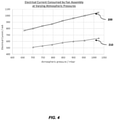
- Figure 4 shows empirical data of the electrical current consumed by the fan assembly 122 in an 'open state' at varying atmospheric pressures.
- the data has a first series 200 of measurements, taken with the third actuator 142 of the outlet port 140 in an 'open state' such that the combustion chamber 110 vented to the atmosphere, and a second series 210 of measurements, taken with the third actuator 142 in a 'closed state' thereby preventing venting of the combustion chamber 110.
- the first and second series each comprise measurements taken across substantially overlapping ranges of atmospheric pressure between 650 and 1030 millibar. Under the respective conditions of both the first and second series 200, 210, the electrical current consumed by the fan assembly 122 increases as the atmospheric pressure increases.
- the electrical current consumed by the fan assembly 122 at any particular atmospheric pressure differs depending on whether the third actuator 142 is in an 'open state' or 'closed state'.
- the first series 200 of measurements shows electrical current increasing from 770 to 1050 milliamps (mA) within its tested range
- the second series 210 shows electrical current increasing from 510 to 650mA within its tested range.
- the controller 152 is able to determine the air mass flow rate and the mass of air inputted into the combustion chamber 110 for the upcoming firing cycle (e.g. interpolation from the performance data of the fan assembly at different electrical current consumptions).
- the elevated pressure of the fuel source causes combustible fluid to move into combustion chamber at a predetermined fuel mass flow rate.
- the time interval for the second 'open state' is determined by the controller based on the feedback signal of the sensor 126 (i.e. the current air mass flow rate and the amount of air moving into the chamber) in order to adapt the mass of fuel moved into the combustion chamber 110, so as to optimise the fuel/air mixture for optimal combustion. Therefore, an optimum fuel/air mixture is provided irrespective of the ambient atmospheric pressure or any other environmental parameter.
- the firing cycle commences igniting the mixture by the ignition device, generating a driving force to propel the piston and drive a fastener into a work surface.
- the combusted fluids are purged from the combustion chamber 110 in readiness for preparing the next firing cycle.
- the third actuator 142 is switched to an 'open state', via a third power driver, by the controller 152 to allow the combusted fluids to be vented to the atmosphere.
- the controller switches the fan assembly 132 into an 'open state' to simultaneously draw fresh air into the combustion chamber 110 and displace the combusted fluids vented through the outlet port. With the combusted fluids purged, the controller 152 is ready to initiate preparation for the next firing cycle.
- the controller 152 bases the time interval of the valve assembly 'open state' on the electrical current consumed by the fan assembly 122 during preparation for the firing stage. In other words, the electrical current consumed by the fan assembly 122 when the outlet port 140 is closed.
- the controller 150 may base the time interval on the current consumed by the fan assembly when the third actuator is open. In other words, the controller may respond to feedback from the sensor 126 when the fan assembly 122 is providing air to displace combusted fluids in the combustion chamber. To this extent, when controlling a time interval, the controller may evaluate, whether the third actuator 142 is in an 'open state' or 'closed state', in order to determine its response to the feedback of the sensor 126.
- the controller 150 may base a time interval (closed state' and/or 'open state') of either one of the first or second actuator on any other indicator signal suitable for determining the ambient atmospheric pressure.
- the indicator may be a direct measurement, for example, from a pressure sensor directly coupled to the controller 150, or a pressure measurement from a pressurised fluid source.
- the indicator signal may be provided by one or more indirect measurement, such as, for example, the rotational speed of the fan assembly 122, or a flow rate measurement device suitably positioned e.g. at the inlet port of the fan assembly 122.
- the indicator signal may also be provided from a remote sensor, for example, atmospheric data provided from another device over a suitable wired or wireless connection, e.g. a mobile phone application.
- the controller 126 may base the time interval of the 'open state' of any one of the first or second actuator on any other data suitable to derive the amount of air and/or fuel mass moved into the combustion chamber at a predetermined time interval, e.g. ambient temperature or relative humidity.
- Any indicator signal, data or measurement provided to the controller may be provided directly or via a suitable intermediary module, for example an analogue-to-digital convertor or wireless receiver.
- Any suitable actuators capable of providing fluids to the combustion chamber may be used, in any appropriate combination.
- the controller 150 controls the time interval of the second actuator based on a parameter associated with the first actuator, so that the time interval of the constant pressure fuel source is controlled depending on a variable characteristic of the ambient atmospheric air.
- a parameter associated with the first actuator controls either one (or both) of the time intervals to be controlled based on characteristics of one or both fluids.
- the time interval of the actuator inputting a fluid with a variable characteristic, such as air may be based on the fixed pressure and time interval of a fluid provided from a pressurised fluid cartridge.
- many variations and combinations of parameters and controls may be adapted in order that the final mixture of fluids within the combustion chamber contains an optimum mass ratio for the specific fluids being used.
- the controller may adapt to varying fluids such that the time intervals may be adjusted to provide different mass ratios depending on the fluids being used.
Landscapes
- Engineering & Computer Science (AREA)
- Chemical & Material Sciences (AREA)
- Combustion & Propulsion (AREA)
- Mechanical Engineering (AREA)
- Portable Nailing Machines And Staplers (AREA)
Priority Applications (3)
| Application Number | Priority Date | Filing Date | Title |
|---|---|---|---|
| CA3125421A CA3125421C (en) | 2020-08-11 | 2021-07-21 | ATTACHMENT TRAINING TOOL |
| AU2021209339A AU2021209339A1 (en) | 2020-08-11 | 2021-07-30 | Fastener driving tool |
| US17/392,958 US11738433B2 (en) | 2020-08-11 | 2021-08-03 | Fastener driving tool |
Applications Claiming Priority (1)
| Application Number | Priority Date | Filing Date | Title |
|---|---|---|---|
| EP20190451 | 2020-08-11 |
Publications (2)
| Publication Number | Publication Date |
|---|---|
| EP3954504A1 true EP3954504A1 (de) | 2022-02-16 |
| EP3954504B1 EP3954504B1 (de) | 2024-01-17 |
Family
ID=72046734
Family Applications (1)
| Application Number | Title | Priority Date | Filing Date |
|---|---|---|---|
| EP21175842.0A Active EP3954504B1 (de) | 2020-08-11 | 2021-05-26 | Werkzeug zum eintreiben von befestigungselementen |
Country Status (4)
| Country | Link |
|---|---|
| US (1) | US11738433B2 (de) |
| EP (1) | EP3954504B1 (de) |
| AU (1) | AU2021209339A1 (de) |
| CA (1) | CA3125421C (de) |
Citations (3)
| Publication number | Priority date | Publication date | Assignee | Title |
|---|---|---|---|---|
| US6123241A (en) * | 1995-05-23 | 2000-09-26 | Applied Tool Development Corporation | Internal combustion powered tool |
| EP1391270A1 (de) * | 2002-08-09 | 2004-02-25 | Hitachi Koki Co., Ltd. | Verbrennungskraftbetriebene Nagelpistole |
| US20040045997A1 (en) * | 2002-09-11 | 2004-03-11 | Birk Daniel J. | Power control system for a framing tool |
Family Cites Families (16)
| Publication number | Priority date | Publication date | Assignee | Title |
|---|---|---|---|---|
| US3850359A (en) | 1973-05-11 | 1974-11-26 | Fastener Corp | Fastener driving tool |
| US6145724A (en) | 1997-10-31 | 2000-11-14 | Illinois Tool Works, Inc. | Combustion powered tool with combustion chamber delay |
| US20020134069A1 (en) | 2001-03-20 | 2002-09-26 | Adams Joseph S. | Combustion chamber system |
| US20020134345A1 (en) | 2001-03-20 | 2002-09-26 | Adams Joseph S. | Combustion chamber system |
| US20020144498A1 (en) | 2001-03-20 | 2002-10-10 | Adams Joseph S. | Combustion chamber system with spool-type pre-combustion chamber |
| US6755159B1 (en) | 2003-01-20 | 2004-06-29 | Illinois Tool Works Inc. | Valve mechanisms for elongated combustion chambers |
| US6912988B2 (en) | 2003-01-24 | 2005-07-05 | Joseph S. Adams | Multiple-front combustion chamber system with a fuel/air management system |
| FR2852546B1 (fr) * | 2003-03-19 | 2006-08-11 | Prospection & Inventions | Procedes de reglage de la puissance d'un appareil a fonctionnement a gaz |
| FR2852547B1 (fr) | 2003-03-19 | 2006-05-12 | Prospection & Inventions | Appareils a fonctionnement a gaz a chambre de pre-compression et chambre de propulsion |
| US7314025B2 (en) | 2005-07-15 | 2008-01-01 | Illinois Tool Works Inc. | Combustion powered fastener-driving tool with interconnected chambers |
| US8087394B2 (en) | 2007-07-25 | 2012-01-03 | Illinois Tool Works Inc. | Dual-level combustion chamber system, for fastener driving tool, having dual-level rotary valve mechanism incorporated therein |
| US9492915B2 (en) | 2011-08-31 | 2016-11-15 | Illinois Tool Works Inc. | High efficiency engine for combustion nailer |
| US9770818B2 (en) | 2011-10-03 | 2017-09-26 | Illinois Tool Works Inc. | Fastener driving tool with portable pressurized power source |
| US9643306B2 (en) | 2014-04-15 | 2017-05-09 | Illinois Tool Works Inc. | Fastener-driving tool including a driving device |
| US9638092B2 (en) | 2014-06-20 | 2017-05-02 | Joseph S. Adams | Combustion-powered tool with flexible silicone control check valve operable between a primary combustion chamber and a secondary combustion chamber |
| EP3189938B1 (de) | 2015-03-10 | 2020-03-11 | Illinois Tool Works Inc. | Perfektionierungen für ein gasfixierungswerkzeug |
-
2021
- 2021-05-26 EP EP21175842.0A patent/EP3954504B1/de active Active
- 2021-07-21 CA CA3125421A patent/CA3125421C/en active Active
- 2021-07-30 AU AU2021209339A patent/AU2021209339A1/en active Pending
- 2021-08-03 US US17/392,958 patent/US11738433B2/en active Active
Patent Citations (3)
| Publication number | Priority date | Publication date | Assignee | Title |
|---|---|---|---|---|
| US6123241A (en) * | 1995-05-23 | 2000-09-26 | Applied Tool Development Corporation | Internal combustion powered tool |
| EP1391270A1 (de) * | 2002-08-09 | 2004-02-25 | Hitachi Koki Co., Ltd. | Verbrennungskraftbetriebene Nagelpistole |
| US20040045997A1 (en) * | 2002-09-11 | 2004-03-11 | Birk Daniel J. | Power control system for a framing tool |
Also Published As
| Publication number | Publication date |
|---|---|
| US11738433B2 (en) | 2023-08-29 |
| US20220048174A1 (en) | 2022-02-17 |
| EP3954504B1 (de) | 2024-01-17 |
| CA3125421A1 (en) | 2022-02-11 |
| AU2021209339A1 (en) | 2022-03-03 |
| CA3125421C (en) | 2025-09-09 |
Similar Documents
| Publication | Publication Date | Title |
|---|---|---|
| US10058985B2 (en) | Control method for hand-held machine tool | |
| US3850359A (en) | Fastener driving tool | |
| US6796476B2 (en) | Power control system for a framing tool | |
| US6554607B1 (en) | Combustion-driven jet actuator | |
| US20160144497A1 (en) | Control method and hand-held power tool | |
| US8925517B2 (en) | Gas-powered tool motor | |
| US10076830B2 (en) | Control method for hand tool machine | |
| AU2019200366B2 (en) | Driving tool | |
| EP1954928B1 (de) | Brennstoffzufuhr- und brennkammersysteme für werkzeuge zum eintreiben von befestigungselementen | |
| EP3954504B1 (de) | Werkzeug zum eintreiben von befestigungselementen | |
| CN101331005B (zh) | 燃烧钉枪的可变点火延迟 | |
| EP2371491A2 (de) | Gasverbrennungs-Eintreibmaschine für Befestigungsmittel | |
| EP4347191B1 (de) | Eintreibgerät für befestigungsmittel | |
| EP1608489B1 (de) | Verfahren zur Einstellung der Kraft einer mit Gas-betriebenen Einrichtung | |
| JP5189317B2 (ja) | 燃焼力作動型鋲打ち機 | |
| JP5516185B2 (ja) | ガス燃焼式打ち込み工具 | |
| JP7004154B2 (ja) | ガス燃焼式打込み工具 | |
| JPH0555278B2 (de) |
Legal Events
| Date | Code | Title | Description |
|---|---|---|---|
| PUAI | Public reference made under article 153(3) epc to a published international application that has entered the european phase |
Free format text: ORIGINAL CODE: 0009012 |
|
| STAA | Information on the status of an ep patent application or granted ep patent |
Free format text: STATUS: THE APPLICATION HAS BEEN PUBLISHED |
|
| AK | Designated contracting states |
Kind code of ref document: A1 Designated state(s): AL AT BE BG CH CY CZ DE DK EE ES FI FR GB GR HR HU IE IS IT LI LT LU LV MC MK MT NL NO PL PT RO RS SE SI SK SM TR |
|
| STAA | Information on the status of an ep patent application or granted ep patent |
Free format text: STATUS: REQUEST FOR EXAMINATION WAS MADE |
|
| 17P | Request for examination filed |
Effective date: 20220729 |
|
| RBV | Designated contracting states (corrected) |
Designated state(s): AL AT BE BG CH CY CZ DE DK EE ES FI FR GB GR HR HU IE IS IT LI LT LU LV MC MK MT NL NO PL PT RO RS SE SI SK SM TR |
|
| GRAP | Despatch of communication of intention to grant a patent |
Free format text: ORIGINAL CODE: EPIDOSNIGR1 |
|
| STAA | Information on the status of an ep patent application or granted ep patent |
Free format text: STATUS: GRANT OF PATENT IS INTENDED |
|
| RIC1 | Information provided on ipc code assigned before grant |
Ipc: B25C 1/08 20060101ALI20230825BHEP Ipc: B25C 1/04 20060101AFI20230825BHEP |
|
| INTG | Intention to grant announced |
Effective date: 20230913 |
|
| P01 | Opt-out of the competence of the unified patent court (upc) registered |
Effective date: 20230919 |
|
| GRAS | Grant fee paid |
Free format text: ORIGINAL CODE: EPIDOSNIGR3 |
|
| GRAA | (expected) grant |
Free format text: ORIGINAL CODE: 0009210 |
|
| STAA | Information on the status of an ep patent application or granted ep patent |
Free format text: STATUS: THE PATENT HAS BEEN GRANTED |
|
| AK | Designated contracting states |
Kind code of ref document: B1 Designated state(s): AL AT BE BG CH CY CZ DE DK EE ES FI FR GB GR HR HU IE IS IT LI LT LU LV MC MK MT NL NO PL PT RO RS SE SI SK SM TR |
|
| REG | Reference to a national code |
Ref country code: GB Ref legal event code: FG4D |
|
| REG | Reference to a national code |
Ref country code: CH Ref legal event code: EP |
|
| REG | Reference to a national code |
Ref country code: DE Ref legal event code: R096 Ref document number: 602021008654 Country of ref document: DE |
|
| REG | Reference to a national code |
Ref country code: IE Ref legal event code: FG4D |
|
| REG | Reference to a national code |
Ref country code: LT Ref legal event code: MG9D |
|
| REG | Reference to a national code |
Ref country code: NL Ref legal event code: MP Effective date: 20240117 |
|
| REG | Reference to a national code |
Ref country code: AT Ref legal event code: MK05 Ref document number: 1650259 Country of ref document: AT Kind code of ref document: T Effective date: 20240117 |
|
| PG25 | Lapsed in a contracting state [announced via postgrant information from national office to epo] |
Ref country code: NL Free format text: LAPSE BECAUSE OF FAILURE TO SUBMIT A TRANSLATION OF THE DESCRIPTION OR TO PAY THE FEE WITHIN THE PRESCRIBED TIME-LIMIT Effective date: 20240117 |
|
| PG25 | Lapsed in a contracting state [announced via postgrant information from national office to epo] |
Ref country code: NL Free format text: LAPSE BECAUSE OF FAILURE TO SUBMIT A TRANSLATION OF THE DESCRIPTION OR TO PAY THE FEE WITHIN THE PRESCRIBED TIME-LIMIT Effective date: 20240117 |
|
| PG25 | Lapsed in a contracting state [announced via postgrant information from national office to epo] |
Ref country code: IS Free format text: LAPSE BECAUSE OF FAILURE TO SUBMIT A TRANSLATION OF THE DESCRIPTION OR TO PAY THE FEE WITHIN THE PRESCRIBED TIME-LIMIT Effective date: 20240517 |
|
| PG25 | Lapsed in a contracting state [announced via postgrant information from national office to epo] |
Ref country code: LT Free format text: LAPSE BECAUSE OF FAILURE TO SUBMIT A TRANSLATION OF THE DESCRIPTION OR TO PAY THE FEE WITHIN THE PRESCRIBED TIME-LIMIT Effective date: 20240117 |
|
| PG25 | Lapsed in a contracting state [announced via postgrant information from national office to epo] |
Ref country code: GR Free format text: LAPSE BECAUSE OF FAILURE TO SUBMIT A TRANSLATION OF THE DESCRIPTION OR TO PAY THE FEE WITHIN THE PRESCRIBED TIME-LIMIT Effective date: 20240418 |
|
| PG25 | Lapsed in a contracting state [announced via postgrant information from national office to epo] |
Ref country code: RS Free format text: LAPSE BECAUSE OF FAILURE TO SUBMIT A TRANSLATION OF THE DESCRIPTION OR TO PAY THE FEE WITHIN THE PRESCRIBED TIME-LIMIT Effective date: 20240417 Ref country code: HR Free format text: LAPSE BECAUSE OF FAILURE TO SUBMIT A TRANSLATION OF THE DESCRIPTION OR TO PAY THE FEE WITHIN THE PRESCRIBED TIME-LIMIT Effective date: 20240117 |
|
| PG25 | Lapsed in a contracting state [announced via postgrant information from national office to epo] |
Ref country code: ES Free format text: LAPSE BECAUSE OF FAILURE TO SUBMIT A TRANSLATION OF THE DESCRIPTION OR TO PAY THE FEE WITHIN THE PRESCRIBED TIME-LIMIT Effective date: 20240117 |
|
| PG25 | Lapsed in a contracting state [announced via postgrant information from national office to epo] |
Ref country code: AT Free format text: LAPSE BECAUSE OF FAILURE TO SUBMIT A TRANSLATION OF THE DESCRIPTION OR TO PAY THE FEE WITHIN THE PRESCRIBED TIME-LIMIT Effective date: 20240117 |
|
| PG25 | Lapsed in a contracting state [announced via postgrant information from national office to epo] |
Ref country code: RS Free format text: LAPSE BECAUSE OF FAILURE TO SUBMIT A TRANSLATION OF THE DESCRIPTION OR TO PAY THE FEE WITHIN THE PRESCRIBED TIME-LIMIT Effective date: 20240417 Ref country code: NO Free format text: LAPSE BECAUSE OF FAILURE TO SUBMIT A TRANSLATION OF THE DESCRIPTION OR TO PAY THE FEE WITHIN THE PRESCRIBED TIME-LIMIT Effective date: 20240417 Ref country code: LT Free format text: LAPSE BECAUSE OF FAILURE TO SUBMIT A TRANSLATION OF THE DESCRIPTION OR TO PAY THE FEE WITHIN THE PRESCRIBED TIME-LIMIT Effective date: 20240117 Ref country code: IS Free format text: LAPSE BECAUSE OF FAILURE TO SUBMIT A TRANSLATION OF THE DESCRIPTION OR TO PAY THE FEE WITHIN THE PRESCRIBED TIME-LIMIT Effective date: 20240517 Ref country code: HR Free format text: LAPSE BECAUSE OF FAILURE TO SUBMIT A TRANSLATION OF THE DESCRIPTION OR TO PAY THE FEE WITHIN THE PRESCRIBED TIME-LIMIT Effective date: 20240117 Ref country code: GR Free format text: LAPSE BECAUSE OF FAILURE TO SUBMIT A TRANSLATION OF THE DESCRIPTION OR TO PAY THE FEE WITHIN THE PRESCRIBED TIME-LIMIT Effective date: 20240418 Ref country code: FI Free format text: LAPSE BECAUSE OF FAILURE TO SUBMIT A TRANSLATION OF THE DESCRIPTION OR TO PAY THE FEE WITHIN THE PRESCRIBED TIME-LIMIT Effective date: 20240117 Ref country code: ES Free format text: LAPSE BECAUSE OF FAILURE TO SUBMIT A TRANSLATION OF THE DESCRIPTION OR TO PAY THE FEE WITHIN THE PRESCRIBED TIME-LIMIT Effective date: 20240117 Ref country code: BG Free format text: LAPSE BECAUSE OF FAILURE TO SUBMIT A TRANSLATION OF THE DESCRIPTION OR TO PAY THE FEE WITHIN THE PRESCRIBED TIME-LIMIT Effective date: 20240117 Ref country code: AT Free format text: LAPSE BECAUSE OF FAILURE TO SUBMIT A TRANSLATION OF THE DESCRIPTION OR TO PAY THE FEE WITHIN THE PRESCRIBED TIME-LIMIT Effective date: 20240117 |
|
| PG25 | Lapsed in a contracting state [announced via postgrant information from national office to epo] |
Ref country code: PL Free format text: LAPSE BECAUSE OF FAILURE TO SUBMIT A TRANSLATION OF THE DESCRIPTION OR TO PAY THE FEE WITHIN THE PRESCRIBED TIME-LIMIT Effective date: 20240117 Ref country code: PT Free format text: LAPSE BECAUSE OF FAILURE TO SUBMIT A TRANSLATION OF THE DESCRIPTION OR TO PAY THE FEE WITHIN THE PRESCRIBED TIME-LIMIT Effective date: 20240517 |
|
| PG25 | Lapsed in a contracting state [announced via postgrant information from national office to epo] |
Ref country code: SE Free format text: LAPSE BECAUSE OF FAILURE TO SUBMIT A TRANSLATION OF THE DESCRIPTION OR TO PAY THE FEE WITHIN THE PRESCRIBED TIME-LIMIT Effective date: 20240117 Ref country code: PT Free format text: LAPSE BECAUSE OF FAILURE TO SUBMIT A TRANSLATION OF THE DESCRIPTION OR TO PAY THE FEE WITHIN THE PRESCRIBED TIME-LIMIT Effective date: 20240517 Ref country code: PL Free format text: LAPSE BECAUSE OF FAILURE TO SUBMIT A TRANSLATION OF THE DESCRIPTION OR TO PAY THE FEE WITHIN THE PRESCRIBED TIME-LIMIT Effective date: 20240117 Ref country code: LV Free format text: LAPSE BECAUSE OF FAILURE TO SUBMIT A TRANSLATION OF THE DESCRIPTION OR TO PAY THE FEE WITHIN THE PRESCRIBED TIME-LIMIT Effective date: 20240117 |
|
| PG25 | Lapsed in a contracting state [announced via postgrant information from national office to epo] |
Ref country code: DK Free format text: LAPSE BECAUSE OF FAILURE TO SUBMIT A TRANSLATION OF THE DESCRIPTION OR TO PAY THE FEE WITHIN THE PRESCRIBED TIME-LIMIT Effective date: 20240117 |
|
| PG25 | Lapsed in a contracting state [announced via postgrant information from national office to epo] |
Ref country code: SM Free format text: LAPSE BECAUSE OF FAILURE TO SUBMIT A TRANSLATION OF THE DESCRIPTION OR TO PAY THE FEE WITHIN THE PRESCRIBED TIME-LIMIT Effective date: 20240117 |
|
| REG | Reference to a national code |
Ref country code: DE Ref legal event code: R097 Ref document number: 602021008654 Country of ref document: DE |
|
| PG25 | Lapsed in a contracting state [announced via postgrant information from national office to epo] |
Ref country code: EE Free format text: LAPSE BECAUSE OF FAILURE TO SUBMIT A TRANSLATION OF THE DESCRIPTION OR TO PAY THE FEE WITHIN THE PRESCRIBED TIME-LIMIT Effective date: 20240117 Ref country code: CZ Free format text: LAPSE BECAUSE OF FAILURE TO SUBMIT A TRANSLATION OF THE DESCRIPTION OR TO PAY THE FEE WITHIN THE PRESCRIBED TIME-LIMIT Effective date: 20240117 |
|
| PG25 | Lapsed in a contracting state [announced via postgrant information from national office to epo] |
Ref country code: SK Free format text: LAPSE BECAUSE OF FAILURE TO SUBMIT A TRANSLATION OF THE DESCRIPTION OR TO PAY THE FEE WITHIN THE PRESCRIBED TIME-LIMIT Effective date: 20240117 |
|
| PG25 | Lapsed in a contracting state [announced via postgrant information from national office to epo] |
Ref country code: SM Free format text: LAPSE BECAUSE OF FAILURE TO SUBMIT A TRANSLATION OF THE DESCRIPTION OR TO PAY THE FEE WITHIN THE PRESCRIBED TIME-LIMIT Effective date: 20240117 Ref country code: SK Free format text: LAPSE BECAUSE OF FAILURE TO SUBMIT A TRANSLATION OF THE DESCRIPTION OR TO PAY THE FEE WITHIN THE PRESCRIBED TIME-LIMIT Effective date: 20240117 Ref country code: RO Free format text: LAPSE BECAUSE OF FAILURE TO SUBMIT A TRANSLATION OF THE DESCRIPTION OR TO PAY THE FEE WITHIN THE PRESCRIBED TIME-LIMIT Effective date: 20240117 Ref country code: EE Free format text: LAPSE BECAUSE OF FAILURE TO SUBMIT A TRANSLATION OF THE DESCRIPTION OR TO PAY THE FEE WITHIN THE PRESCRIBED TIME-LIMIT Effective date: 20240117 Ref country code: DK Free format text: LAPSE BECAUSE OF FAILURE TO SUBMIT A TRANSLATION OF THE DESCRIPTION OR TO PAY THE FEE WITHIN THE PRESCRIBED TIME-LIMIT Effective date: 20240117 Ref country code: CZ Free format text: LAPSE BECAUSE OF FAILURE TO SUBMIT A TRANSLATION OF THE DESCRIPTION OR TO PAY THE FEE WITHIN THE PRESCRIBED TIME-LIMIT Effective date: 20240117 |
|
| PLBE | No opposition filed within time limit |
Free format text: ORIGINAL CODE: 0009261 |
|
| STAA | Information on the status of an ep patent application or granted ep patent |
Free format text: STATUS: NO OPPOSITION FILED WITHIN TIME LIMIT |
|
| PG25 | Lapsed in a contracting state [announced via postgrant information from national office to epo] |
Ref country code: IT Free format text: LAPSE BECAUSE OF FAILURE TO SUBMIT A TRANSLATION OF THE DESCRIPTION OR TO PAY THE FEE WITHIN THE PRESCRIBED TIME-LIMIT Effective date: 20240117 |
|
| 26N | No opposition filed |
Effective date: 20241018 |
|
| REG | Reference to a national code |
Ref country code: CH Ref legal event code: PL |
|
| PG25 | Lapsed in a contracting state [announced via postgrant information from national office to epo] |
Ref country code: IT Free format text: LAPSE BECAUSE OF FAILURE TO SUBMIT A TRANSLATION OF THE DESCRIPTION OR TO PAY THE FEE WITHIN THE PRESCRIBED TIME-LIMIT Effective date: 20240117 |
|
| PG25 | Lapsed in a contracting state [announced via postgrant information from national office to epo] |
Ref country code: MC Free format text: LAPSE BECAUSE OF FAILURE TO SUBMIT A TRANSLATION OF THE DESCRIPTION OR TO PAY THE FEE WITHIN THE PRESCRIBED TIME-LIMIT Effective date: 20240117 |
|
| PG25 | Lapsed in a contracting state [announced via postgrant information from national office to epo] |
Ref country code: LU Free format text: LAPSE BECAUSE OF NON-PAYMENT OF DUE FEES Effective date: 20240526 |
|
| PG25 | Lapsed in a contracting state [announced via postgrant information from national office to epo] |
Ref country code: MC Free format text: LAPSE BECAUSE OF FAILURE TO SUBMIT A TRANSLATION OF THE DESCRIPTION OR TO PAY THE FEE WITHIN THE PRESCRIBED TIME-LIMIT Effective date: 20240117 Ref country code: LU Free format text: LAPSE BECAUSE OF NON-PAYMENT OF DUE FEES Effective date: 20240526 Ref country code: CH Free format text: LAPSE BECAUSE OF NON-PAYMENT OF DUE FEES Effective date: 20240531 |
|
| REG | Reference to a national code |
Ref country code: BE Ref legal event code: MM Effective date: 20240531 |
|
| PG25 | Lapsed in a contracting state [announced via postgrant information from national office to epo] |
Ref country code: IE Free format text: LAPSE BECAUSE OF NON-PAYMENT OF DUE FEES Effective date: 20240526 |
|
| PG25 | Lapsed in a contracting state [announced via postgrant information from national office to epo] |
Ref country code: SI Free format text: LAPSE BECAUSE OF FAILURE TO SUBMIT A TRANSLATION OF THE DESCRIPTION OR TO PAY THE FEE WITHIN THE PRESCRIBED TIME-LIMIT Effective date: 20240117 Ref country code: BE Free format text: LAPSE BECAUSE OF NON-PAYMENT OF DUE FEES Effective date: 20240531 |
|
| PGFP | Annual fee paid to national office [announced via postgrant information from national office to epo] |
Ref country code: DE Payment date: 20250529 Year of fee payment: 5 |
|
| PGFP | Annual fee paid to national office [announced via postgrant information from national office to epo] |
Ref country code: GB Payment date: 20250527 Year of fee payment: 5 |
|
| PGFP | Annual fee paid to national office [announced via postgrant information from national office to epo] |
Ref country code: FR Payment date: 20250526 Year of fee payment: 5 |
|
| PG25 | Lapsed in a contracting state [announced via postgrant information from national office to epo] |
Ref country code: HU Free format text: LAPSE BECAUSE OF FAILURE TO SUBMIT A TRANSLATION OF THE DESCRIPTION OR TO PAY THE FEE WITHIN THE PRESCRIBED TIME-LIMIT; INVALID AB INITIO Effective date: 20210526 |
|
| PG25 | Lapsed in a contracting state [announced via postgrant information from national office to epo] |
Ref country code: CY Free format text: LAPSE BECAUSE OF FAILURE TO SUBMIT A TRANSLATION OF THE DESCRIPTION OR TO PAY THE FEE WITHIN THE PRESCRIBED TIME-LIMIT; INVALID AB INITIO Effective date: 20210526 |