EP3954482B1 - Werkzeugsystem - Google Patents
Werkzeugsystem Download PDFInfo
- Publication number
- EP3954482B1 EP3954482B1 EP20191090.8A EP20191090A EP3954482B1 EP 3954482 B1 EP3954482 B1 EP 3954482B1 EP 20191090 A EP20191090 A EP 20191090A EP 3954482 B1 EP3954482 B1 EP 3954482B1
- Authority
- EP
- European Patent Office
- Prior art keywords
- cutting insert
- tool system
- neck
- interchangeable cutting
- tool
- Prior art date
- Legal status (The legal status is an assumption and is not a legal conclusion. Google has not performed a legal analysis and makes no representation as to the accuracy of the status listed.)
- Active
Links
Images


Classifications
-
- B—PERFORMING OPERATIONS; TRANSPORTING
- B23—MACHINE TOOLS; METAL-WORKING NOT OTHERWISE PROVIDED FOR
- B23B—TURNING; BORING
- B23B27/00—Tools for turning or boring machines; Tools of a similar kind in general; Accessories therefor
- B23B27/007—Tools for turning or boring machines; Tools of a similar kind in general; Accessories therefor for internal turning
-
- B—PERFORMING OPERATIONS; TRANSPORTING
- B23—MACHINE TOOLS; METAL-WORKING NOT OTHERWISE PROVIDED FOR
- B23B—TURNING; BORING
- B23B27/00—Tools for turning or boring machines; Tools of a similar kind in general; Accessories therefor
- B23B27/14—Cutting tools of which the bits or tips or cutting inserts are of special material
- B23B27/16—Cutting tools of which the bits or tips or cutting inserts are of special material with exchangeable cutting bits or cutting inserts, e.g. able to be clamped
- B23B27/1614—Cutting tools of which the bits or tips or cutting inserts are of special material with exchangeable cutting bits or cutting inserts, e.g. able to be clamped with plate-like cutting inserts of special shape clamped against the walls of the recess in the shank by a clamping member acting upon the wall of a hole in the insert
- B23B27/1622—Cutting tools of which the bits or tips or cutting inserts are of special material with exchangeable cutting bits or cutting inserts, e.g. able to be clamped with plate-like cutting inserts of special shape clamped against the walls of the recess in the shank by a clamping member acting upon the wall of a hole in the insert characterised by having a special shape
-
- B—PERFORMING OPERATIONS; TRANSPORTING
- B23—MACHINE TOOLS; METAL-WORKING NOT OTHERWISE PROVIDED FOR
- B23B—TURNING; BORING
- B23B2200/00—Details of cutting inserts
- B23B2200/12—Side or flank surfaces
- B23B2200/121—Side or flank surfaces with projections
-
- B—PERFORMING OPERATIONS; TRANSPORTING
- B23—MACHINE TOOLS; METAL-WORKING NOT OTHERWISE PROVIDED FOR
- B23B—TURNING; BORING
- B23B2200/00—Details of cutting inserts
- B23B2200/36—Other features of cutting inserts not covered by B23B2200/04 - B23B2200/32
- B23B2200/369—Mounted tangentially, i.e. where the rake face is not the face with the largest area
-
- B—PERFORMING OPERATIONS; TRANSPORTING
- B23—MACHINE TOOLS; METAL-WORKING NOT OTHERWISE PROVIDED FOR
- B23B—TURNING; BORING
- B23B2205/00—Fixation of cutting inserts in holders
- B23B2205/12—Seats for cutting inserts
-
- B—PERFORMING OPERATIONS; TRANSPORTING
- B23—MACHINE TOOLS; METAL-WORKING NOT OTHERWISE PROVIDED FOR
- B23B—TURNING; BORING
- B23B2250/00—Compensating adverse effects during turning, boring or drilling
- B23B2250/12—Cooling and lubrication
Definitions
- the present invention relates to a tool system comprising a tool carrier and an interchangeable cutting insert.
- turning tools can also have multiple cutting edges. By rotating the turning tool, a fresh cutting edge can be used when one cutting edge becomes worn, without having to completely remove the turning tool from the machine. This avoids delays caused by replacing the turning tool and the resulting need for repositioning it in the machine.
- the DE 10 2004 013 835 A1 describes such a turning tool, designed for internal turning.
- Several cutting edges which can be selectively engaged, radiate outward in a star shape from a tool head that is integrally connected to a tool shank.
- finishing tool which has six tangentially arranged cutting edges on its face, all of which are of identical design. Support surfaces adjacent to each cutting edge rest against the wall of a bore to be machined.
- a piercing knife is from the DE 295 08 900 This has a cutting edge that can be brought into cutting engagement and is arranged on a clamping holder. The cutting edge is attached to a seat of the clamping holder by means of a screw.
- An object of the present invention is to provide a tool system which can be used in particular as a turning tool and on which several cutting edges are arranged in such a way that an active cutting edge can be used without the risk of damaging the passive cutting edges.
- a tool system which has a tool holder and an interchangeable cutting insert with preferably at least three cutting edges. It is particularly preferred that it has exactly three cutting edges.
- a cutting edge is understood not only to be the ground area of a cutting part, but the entire cutting part which is delimited by the rake face and flank face.
- the tool holder has a neck with a seat on which the interchangeable cutting insert is arranged.
- a neck is understood to be an area which is usually adapted to a diameter to be machined.
- the neck usually has a circular-cylindrical cross-section.
- Adjacent to the neck of the tool holder is a receiving area which serves to clamp the tool holder in a machine or in another receiving element.
- Preferred materials for the tool holder are steel, a combination of hard metal and steel or a combination of heavy metal and steel.
- the cutting edges of the interchangeable insert are essentially orthogonal to the longitudinal axis of the tool holder. This allows the tool system to be used as a turning tool. It is particularly suitable for machining diameters from 7.8 mm upwards.
- the neck has a protective area that projects beyond the seat along its longitudinal axis and surrounds all cutting edges of the interchangeable cutting insert except one. In particular, it extends at least to a ground area of these cutting edges. While the exposed cutting edge can be used for material processing, all non-working cutting edges are protected by the protective area from potential chips and associated damage.
- the protective area is preferably formed integrally with the neck.
- a length of the protective area along the longitudinal axis is equal to a length of the interchangeable cutting insert.
- the protective area can also be used to securely fix the interchangeable cutting insert to the tool holder and ensure effective transmission of forces acting on the active cutting edge via the interchangeable cutting insert into the tool holder.
- the protective area it is preferable for the protective area to be in partial contact with the interchangeable cutting insert. This contact preferably occurs on a peripheral surface of the interchangeable cutting insert.
- the protective area is preferably designed as a circular arc-shaped projection. As such, it can continue the neck along the longitudinal axis of the tool holder and tightly enclose the interchangeable cutting insert. For each cutting edge it surrounds, the protective area preferably has a recess in which the respective cutting edge is received. In this way, the protective area can have a continuously extending surface on its outer side, i.e. the side facing a workpiece, while its inner side, i.e. the side facing the interchangeable cutting insert, has the recesses. As a result, the thickness of the protective area varies in the area of the passive cutting edges.
- the circumferential length of the protective area corresponds to at least 33% of the circumference of the neck. If the neck has a circular cross-section, this means that the protective area extends over a circular arc with an angle of at least 120°. Particularly preferably, the circumferential length of the protective area corresponds to at least 50% of the circumference of the neck.
- the neck has a circular cross-section, this means that the protection area extends over an arc with an angle of at least 180°.
- each recess is preferably angled relative to the longitudinal axis. This enables the passive cutting edges to be accommodated when the interchangeable cutting insert is angled relative to the longitudinal axis of the tool holder. Such an angle is preferred. This means that the interchangeable cutting insert is clamped to the seat not along the longitudinal axis of the tool holder, but at an angle to it. This results in advantageous force absorption by the tool system when machining a workpiece.
- An angle of the interchangeable cutting insert relative to the longitudinal axis of a maximum of 10° is preferred and a maximum of 5° is particularly preferred.
- the angle is preferably at least 1° and particularly preferably at least 2°.
- the seat is angled relative to the longitudinal axis by the same angle as the interchangeable cutting insert.
- the seat has at least one engagement element, into which an engagement element of the interchangeable cutting insert engages.
- this engagement element is arranged on the side of the interchangeable cutting insert facing the neck.
- the number of engagement elements on the interchangeable cutting insert is in particular equal to the number of cutting edges of the interchangeable cutting insert.
- the engagement element takes up a Part of the forces acting on the interchangeable cutting insert transverse to the longitudinal axis are absorbed, so that these do not have to be absorbed exclusively by a clamping device. This protects the interchangeable cutting insert from twisting.
- the at least one engagement element of the seat and the at least one engagement element of the interchangeable cutting insert are each a toothing.
- the at least one engagement element of the seat and the at least one engagement element of the interchangeable cutting insert are each a side of a polygon. If the interchangeable cutting insert is angled relative to the longitudinal axis of the tool carrier, the interchangeable cutting insert can then be pulled towards the side surfaces at the level of the passive cutting edges when the clamping screw is turned, thus securely clamping the interchangeable cutting insert.
- the seat and the interchangeable cutting insert each have exactly one engagement element.
- One of the engagement elements is concave, and the corresponding engagement element is convex.
- the interchangeable cutting insert is aligned via a point at which a passive cutting edge rests in the protective area.
- the engagement elements of the interchangeable cutting insert can be supplied in an unmachined, sintered state. However, depending on requirements, the engagement elements can also be ground. The engagement elements on the seat are then adjusted accordingly.
- the clamping device used is preferably a clamping screw that runs through one end face of the insert into the seat.
- This clamping of the tool system on the end face has advantages over a Tension along the diameter axis of the tool holder has the advantage that the neck of the tool holder is not unnecessarily weakened, which enables a more stable turning process and higher overhang lengths.
- a coolant channel runs through a receiving area and the neck of the tool carrier and opens into at least one outlet opening on a circumferential surface of the neck. While coolant channels are generally desirable in such tool systems, they often cannot be realized by tensioning them along the carrier diameter axis, as this leaves insufficient space for the coolant channel in the neck.
- the tool system according to the invention still has sufficient space in its neck to allow the positioning of a coolant channel.
- it has an outlet opening facing the active cutting edge. This enables active cooling of the active cutting edge. In another preferred embodiment of the tool system, it has an outlet opening facing away from the active cutting edge. This enables passive cooling of the active cutting edge.
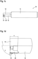
- a tool system according to a first embodiment of the invention in the assembled state is shown in the Figures 1a to 1d shown.
- the tool system comprises a tool holder 10 with a circular-cylindrical receiving area 11 and a circular-cylindrical neck 12, which in this case is made of steel.
- the receiving area 11 is intended to accommodate the tool system in a machine.
- the neck 12 carries an interchangeable cutting insert 20 with hard metal cutting edges on its front side. It has a smaller diameter than the receiving area 11 and is adapted to the diameter of a workpiece to be machined.
- a coolant channel runs through the receiving area 11 and the neck 12 and opens into an opening 13 in the neck 12.
- This opening 13 and an active cutting edge 21 of the interchangeable cutting insert 20 lie on a common straight line that runs parallel to the longitudinal axis L of the tool holder 10.
- the length of the protective zone 14 along the longitudinal axis L corresponds to the length of the interchangeable cutting insert 20.
- the longitudinal axis of the interchangeable cutting insert 20 is inclined by an angle ⁇ of 2° relative to the longitudinal axis L of the tool holder 10.
- the angle ⁇ of the active cutting edge 21 to the longitudinal axis L of the tool holder 10 is therefore 88°.
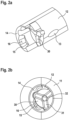
- the protective area 14 is shown in detail. This has two recesses 15 in order to accommodate two passive cutting edges of the interchangeable cutting insert 20. For one of these recesses 15, Figure 2a its side surface 16 is visible. Since the seat 30 on the neck 12, on which the interchangeable cutting insert 20 rests, is inclined by the same angle ⁇ as the interchangeable cutting insert 20 relative to the longitudinal axis L of the tool holder 10, the side surface 16 is also angled relative to the longitudinal axis L of the tool holder 10, in order to allow the cutting edge to be positioned therein to be received without it contacting the seat 14. However, between the recess 16 and the seat 30, the interchangeable cutting insert 20 rests against the protective area 14 and is thus additionally stabilized.
- the seat 30 has engagement elements 31 in the form of a gearing with three teeth. Furthermore, a threaded bore 32 runs orthogonally through its center. This bore is inclined by an angle ⁇ relative to the longitudinal axis L of the tool carrier 10.
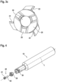
- the interchangeable cutting insert 20 has three cutting edges 21 to 23.
- the first cutting edge 21 acts as the active cutting edge and the other cutting edges 22, 23 as passive cutting edges, which are surrounded by the protective area 14 and received in its recesses 15.
- a circular-cylindrical opening 24 extends through the interchangeable cutting insert 20 along the longitudinal axis thereof, which opening has a countersink on its front side.
- engagement elements 25 in the form of a toothing with three teeth are arranged. These are designed to engage with the engagement elements 31 of the seat 30.
- Both the engagement elements 25 of the interchangeable cutting insert 20 and the engagement elements 31 of the seat 30 are arranged at an angle of 120° to one another. If the interchangeable cutting insert 20 is placed on the seat 30 in such a way that the teeth 25, 31 engage with one another, the first cutting edge 21, for example, is thereby engaged in the Figures 1a to 1d shown position.
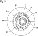
- the Figures 4 and 5 show how the interchangeable cutting insert 20 can be clamped to the seat 30 using a clamping screw 40.
- the clamping screw has a head 41 and a screw shaft 42. After the interchangeable cutting insert 20 has been positioned on the seat 30 so that the teeth 25, 31 engage with each other, the clamping screw 40 is guided through the opening 24 of the interchangeable cutting insert 20 and the screw shaft 42 is screwed into the threaded bore 32 of the seat 30. The head 41 of the clamping screw 40 is countersunk into the recess of the opening 24.
- the interchangeable cutting insert 20 can be removed from the seat 30 along the clamping screw 40, which is angled by an angle ⁇ of 2° from the longitudinal axis L of the tool holder 10, until the cutting edges 21 to 23 protrude beyond the protective area 14.
- the interchangeable cutting insert 20 can then be rotated by 120° and subsequently clamped again to the seat 30 using the clamping screw 40. This moves one of the two other previously passive cutting edges 22, 23 into the active position and positions the worn cutting edge 21 in one of the recesses 15 of the protective area 14. Removing the tool holder 10 from the machine is not necessary for this purpose.
- a projection in the shape of an equilateral triangle is arranged on the seat 30 instead of the toothing.
- Each side of the triangle forms an engagement element 31.
- a recess is formed, which also has the shape of an equilateral triangle. Its sides also function as engagement elements 25, into which the engagement elements 31 of the seat 30 engage.
- the seat 30 has a hemispherical concave recess as the engagement element 31 instead of the toothing.
- a hemispherical convex projection is arranged as the engagement element 25, which engages with the engagement element 31 of the seat 30.
Landscapes
- Engineering & Computer Science (AREA)
- Mechanical Engineering (AREA)
- Cutting Tools, Boring Holders, And Turrets (AREA)
Description
- Die vorliegende Erfindung betrifft ein Werkzeugsystem, das einen Werkzeugträger und einen Wechselschneideinsatz aufweist.
- Drehmeißel sind, auch wenn ihre Schneiden aus Hartmetall oder anderen Hartwerkstoffen bestehen, einem starken Verschleiß ausgesetzt und müssen häufig nachgeschliffen oder ausgewechselt werden. Drehmeißel aus Vollhartmetall haben aufgrund ihres Materialpreises und Herstellungspreises meistens nur eine Schneide und sind nur für ein begrenztes Einsatzgeiet ausgelegt. Nach dem Verschleiß müssen sie aus der Maschine entfernt werden.
- Allerdings können Drehmeißel auch mehrere Schneiden aufweisen. Durch Drehen des Drehmeißels kann so bei Abnutzung einer Schneide eine frische Schneide zum Einsatz gebracht werden, ohne den Drehmeißel vollständig aus einer Maschine herausnehmen zu müssen. Auf diese Weise werden Verzögerungen durch einen Austausch des Drehmeißels und einer deswegen notwendigen Neupositionierung in der Maschine vermieden.
- Die
DE 10 2004 013 835 A1 beschreibt einen solchen Drehmeißel, der für das Innendrehen ausgelegt ist. Mehrere wahlweise in Schneideingriff bringbare Schneiden gehen sternförmig von einem Meißelkopf aus, der einstückig mit einem Meißelschaft verbunden ist. - Beim Einsatz eines solchen Werkzeugs kann es allerdings zu unplanmäßigen Beschädigungen der nicht im Einsatz befindlichen Schneiden kommen. Ein kleiner Span, der von der aktiven Schneide abgehoben wird und der die passiven Schneiden streift, reicht oftmals schon aus, um diese so zu beschädigen, dass sie keinen hohen Ansprüchen an die Bearbeitungsqualität mehr genügen. Damit wäre der gesamte Wechselschneideinsatz Ausschuss.
- In der
WO 2007/006575 A1 wird ein Feinbearbeitungswerkzeug beschrieben, welches an seiner Stirnseite sechs tangential angeordnete Schneiden aufweist, die alle gleich ausgebildet sind. Jeweils an die Schneiden angrenzende Stützflächen liegen an einer zu bearbeitenden Wand einer Bohrung an. - Ein Einstechmesser ist aus der
DE 295 08 900 bekannt. Dieses weist eine in Schneideingriff bringbare Schneide auf, die an einem Klemmhalter angeordnet ist. Die Schneide ist mittels einer Schraube auf einem Sitz eines Klemmhalters befestigt. - Eine Aufgabe der vorliegenden Erfindung besteht darin ein Werkzeugsystem bereitzustellen, das insbesondere als Drehmeißel eingesetzt werden kann und an dem mehrere Schneiden so angeordnet ist, dass eine aktive Schneide eingesetzt werden kann, ohne dass dabei die Gefahr besteht, die passiven Schneiden zu beschädigen.
- Diese Aufgabe wird erfindungsgemäß durch ein Werkzeugsystem gelöst, welches einen Werkzeugträger und einen Wechselschneideinsatz mit vorzugsweise mindestens drei Schneiden aufweist. Besonders bevorzugt weist er genau drei Schneiden auf. Unter einer Schneide wird dabei nicht nur der geschliffene Bereich eines Schneidteils verstanden, sondernd das gesamte Schneidteil, das durch Spanfläche und Freifläche begrenzt wird. Der Werkzeugträger weist einen Hals mit einem Sitz auf, auf dem der Wechselschneideinsatz angeordnet ist. Unter einem Hals wird dabei ein Bereich verstanden, der üblicherweise an einen zu bearbeitenden Durchmesser angepasst ist. Der Hals weist üblicherweise einen kreiszylinderförmigen Querschnitt auf. An den Hals des Werkzeugträgers schließt sich ein Aufnahmebereich an, der zum Spannen des Werkzeugträgers in einer Maschine oder in einem anderen Aufnahmeelement dient. Bevorzugte Materialien für den Werkzeugträger sind Stahl, eine Kombination aus Hartmetall und Stahl oder eine Kombination aus Schwermetall und Stahl.
- Die Schneiden des Wechselschneideinsatzes stehen insbesondere im Wesentlichen orthogonal zu der Längsachse des Werkzeugträgers. Dies ermöglicht einen Einsatz des Werkzeugsystems als Drehmeißel. Dabei ist es insbesondere für die Bearbeitung von Durchmessern ab 7,8 mm geeignet.
- Der Hals weist einen Schutzbereich auf, welcher entlang der Längsachse über den Sitz vorspringt und der alle Schneiden des Wechselschneideinsatzes mit Ausnahme einer Schneide umgibt. Dabei erstreckt er sich insbesondere mindestens bis zu einem geschliffenen Bereich dieser Schneiden. Während die freiliegende Schneide zur Materialbearbeitung genutzt werden kann, werden alle nicht arbeitenden Schneiden durch den Schutzbereich vor möglichen Spänen und einer damit einhergehenden Beschädigung geschützt. Der Schutzbereich ist vorzugsweise einstückig mit dem Hals ausgebildet.
- Um einen besonders zuverlässigen Schutz der nicht arbeitenden Schneiden vor möglichen Spänen zu gewährleisten, ist es bevorzugt, dass eine Länge des Schutzbereichs entlang der Längsachse gleich einer Länge des Wechselschneideinsatzes ist.
- Neben der Funktion, die nicht arbeitenden Schneiden zu schützen, kann der Schutzbereich weiterhin auch dazu genutzt werden, um den Wechselschneideinsatz besonders sicher am Werkzeugträger zu fixieren und eine gute Einleitung von auf die aktive Schneide wirkenden Kräften über den Wechselschneideinsatz in den Werkzeugträger zu gewährleisten. Hierzu ist es bevorzugt, dass der Schutzbereich abschnittsweise an dem Wechselschneideinsatz anliegt. Dieses Anliegen erfolgt dabei bevorzugt an einer Mantelfläche des Wechselschneideinsatzes.
- Der Schutzbereich ist vorzugsweise als kreisbogenförmiger Vorsprung ausgeführt. Als solcher kann er den Hals entlang der Längsachse des Werkzeugträgers fortsetzen und den Wechselschneideinsatz eng umschließen. Für jede von ihm umgebene Schneide weist der Schutzbereich vorzugsweise eine Ausnehmung auf, in welcher die jeweilige Schneide aufgenommen ist. Auf diese Weise kann der Schutzbereich an seiner Außenseite, also der einem Werkstück zugewandten Seite, eine stetig verlaufende Oberfläche aufweisen, während seine Innenseite, also die dem Wechselschneideinsatz zugewandte Seite, die Ausnehmungen aufweist. Hierdurch variiert die Dicke des Schutzbereiches im Bereich der passiven Schneiden. Um einen zuverlässigen Schutz der passiven Schneiden zu gewährleisten ist es weiterhin bevorzugt, dass die Umfangslänge des Schutzbereiches, die entlang seiner gekrümmten Außenfläche gemessen wird, mindestens 33 % des Umfangs des Halses entspricht. Wenn der Hals einen kreisförmigen Querschnitt aufweist, so bedeutet dies, dass der Schutzbereich sich über einen Kreisbogen mit einem Winkel von mindestens 120° erstreckt. Besonders bevorzugt entspricht die Umfangslänge des Schutzbereiches mindestens 50 % des Umfangs des Halses.
- Wenn der Hals einen kreisförmigen Querschnitt aufweist, so bedeutet dies, dass der Schutzbereich sich über einen Kreisbogen mit einem Winkel von mindestens 180° erstreckt.
- Eine Seitenfläche jeder Ausnehmung ist gegenüber der Längsachse vorzugsweise abgewinkelt. Dies ermöglicht eine Aufnahme der passiven Schneiden, wenn der Wechselschneideinsatz gegenüber der Längsachse des Werkzeugträgers abgewinkelt ist. Eine solche Abwinkelung ist bevorzugt. Diese bewirkt nämlich, dass ein Spannen des Wechselschneideinsatzes an dem Sitz nicht entlang der Längsachse des Werkzeugträgers, sondern in einem Winkel hierzu erfolgt. Dies bewirkt eine vorteilhafte Kraftaufnahme des Werkzeugsystems bei der Bearbeitung eines Werkstücks. Dabei ist eine Abwinkelung des Wechselschneideinsatzes gegenüber der Längsachse von maximal 10° bevorzugt und von maximal 5° besonders bevorzugt. Weiterhin beträgt die Abwinkelung bevorzugt mindestens 1° und besonders bevorzugt mindestens 2°. Der Sitz ist dabei gegenüber der Längsachse um denselben Winkel abgewinkeit, wie der Wechselschneideinsatz.
- Weiterhin weist der Sitz mindestens ein Eingriffselement auf, in welches ein Eingriffselement des Wechselschneideinsatzes eingreift. Dieses ist hierzu an der dem Hals zugewandten Seite des Wechselschneideinsatzes angeordnet. Die Anzahl der Eingriffselemente am Wechselschneideinsatz ist insbesondere gleich der Anzahl der Schneiden des Wechselschneideinsatzes. Die beiden ineinandergreifenden Eingriffselemente bieten zwei Vorteile: Wird der Wechselschneideinsatz erstmals auf den Hals aufgesetzt oder wird er auf dem Hals gedreht, wenn eine abgenutzte Schneide in eine passive Position gebracht werden soll, um gleichzeitig eine bisher unbenutzte Schneide aus ein passiven Position in die aktive Position zu bewegen, so gibt das Eingriffelement dem Benutzer eine haptische Rückmeldung wann der Wechselschneideinsatz im korrekten Winkel zum Sitz positioniert wurde, sodass nun ein Spannen des Wechselschneideinsatzes erfolgen kann. Dies verhindert einen unsachgemäßen Einbau. Zum anderen nimmt das Eingriffelement einen Teil von quer zur Längsachse auf den Wechselschneideinsatz wirkenden Kräften auf, sodass diese nicht ausschließlich durch ein Spannmittel aufgenommen werden müssen. Dadurch wird der Wechselschneideinsatz vor Verdrehungen geschützt.
- In einer bevorzugten Ausführungsform des Werkzeugsystems handelt es sich bei dem mindestens einen Eingriffelement des Sitzes und bei dem mindestens einen Eingriffelement des Wechselschneideinsatzes jeweils um eine Verzahnung. In einer anderen bevorzugten Ausführungsform des Werkzeugsystems handelt es sich bei dem mindestens einen Eingriffelement des Sitzes und bei dem mindestens einen Eingriffelement des Wechselschneideinsatzes jeweils um eine Seite eines Polygons. Wenn der Wechselschneideinsatz gegenüber der Längsachse des Werkzeugträgers abgewinkelt ist kann der Wechselschneideinsatz dann beim Drehen der Spannschraube in Richtung der Seitenflächen auf Höhe der passiven Schneiden gezogen werden und der Wechselschneideinsatz so sicher gespannt werden.
- In noch einer anderen bevorzugten Ausführungsform der Erfindung weisen der Sitz und der Wechselschneideinsatz jeweils genau ein Eingriffelement auf. Dabei ist eines der Eingriffselemente konkav und das korrespondierende Eingriffselement konvex. Eine Ausrichtung des Wechselschneideinsatzes erfolgt dabei über einen Punkt, an dem eine passive Schneide im Schutzbereich anliegt.
- Die Eingreifelemente des Wechselschneideinsatzes können in einem unbearbeiteten, gesinterten Zustand vorliegen. Die Eingreifelemente können aber, je nach Anforderung auch geschliffen werden. Die Eingreifelemente am Sitz werden dann entsprechend angepasst.
- Als Spannmittel wird vorzugsweise eine Spannschraube verwendet, die durch eine Stirnseite des Wechselschneideinsatzes in den Sitz hinein verläuft. Diese stirnseitige Spannung des Werkzeugsystems hat gegenüber einer Spannung entlang der Durchmesserachse des Werkzeugträgers den Vorteil, dass der Hals des Werkzeugträgers nicht unnötig geschwächt wird, was einen stabileren Drehprozess und höhere Auskraglängen ermöglicht.
- Weiterhin ist es bevorzugt, dass ein Kühlmittelkanal durch einen Aufnahmebereich und den Hals des Werkzeugträgers verläuft und in mindestens einer Auslassöffnung an einer Mantelfläche des Halses mündet. Während Kühlmittelkanäle in derartigen Werkzeugsystemen grundsätzlich wünschenswert sind, können sie durch eine Spannung entlang der Trägerdurchmesserachse oftmals nicht realisiert werden, da aufgrund dieser kein ausreichender Bauraum für den Kühlmittelkanal im Hals verbleibt. Das erfindungsgemäße Werkezugsystem weist hingegen in seinem Hals noch ausreichend Platz auf, um einen Kühlmittelkanal positionieren zu können.
- In einer bevorzugten Ausführungsform des Werkzeugsystems, weist es eine Auslassöffnung auf, die der aktiven Schneide zugewandt ist. Dies ermöglicht eine aktive Kühlung der aktiven Schneide. In einer anderen bevorzugten Ausführungsform des Werkzeugsystems, weist es eine Auslassöffnung auf, die von der aktiven Schneide abgewandt ist. Dies ermöglicht eine passive Kühlung der aktiven Schneide.
- Ausführungsbeispiele der Erfindung sind in den Zeichnungen dargestellt und werden in der nachfolgenden Beschreibung näher erläutert.
-
Figur 1a zeigt eine isometrische Darstellung eines Werkzeugsystems gemäß einem Ausführungsbeispiel der Erfindung. -
Figur 1b zeigt eine Seitenansicht des Werkzeugsystems gemäßFigur 1a . -
Figur 1c zeigt eine Seitenansicht des Werkzeugsystems gemäßFigur 1a , welches gegenüber der Darstellung inFigur 1b entlang seiner Längsachse um 90° gedreht wurde. -
Figur 1d zeigt eine Detailansicht ausFigur 1c . -
Figur 2a zeigt eine isometrische Detailansicht des Halses eines Werkzeugträgers eines Werkzeugsystems gemäß einem Ausführungsbeispiel der Erfindung. -
Figur 2b zeigt eine Ansicht auf den inFigur 2a dargestellten Hals eines Werkzeugträgers von seiner Stirnseite. -
Figur 3a zeigt eine Seitenansicht eines Wechselschneideinsatzes eines Werkzeugsystems gemäß einem Ausführungsbeispiel der Erfindung. -
Figur 3b zeigt eine isometrische Darstellung des Wechselschneideinsatzes gemäßFigur 3a . -
Figur 3c zeigt eine Ansicht des Wechselschneideinsatzes gemäßFigur 3a von seiner Rückseite. -
Figur 4 zeigt eine isometrische Explosionsdarstellung eines Werkzeugsystems gemäß einem Ausführungsbeispiel der Erfindung. -
Figur 5 zeigt eine Ansicht auf ein Werkzeugsystem gemäß einem Ausführungsbeispiel der Erfindung von seiner Stirnseite. - Ein Werkzeugsystem gemäß einem ersten Ausführungsbeispiel der Erfindung im zusammengebauten Zustand ist in den
Figuren 1a bis 1d dargestellt. Das Werkzeugsystem weist einen Werkzeugträger 10 mit einem kreiszylinderförmigen Aufnahmebereich 11 und einem kreiszylinderförmigen Hals 12 auf, der vorliegend aus Stahl besteht. Der Aufnahmebereich 11 ist dazu vorgesehen, um das Werkzeugsystem in einer Maschine aufzunehmen. Der Hals 12 trägt an seiner Stirnseite einen Wechselschneideinsatz 20 mit Schneiden aus Hartmetall. Er weist einen geringeren Durchmesser als der Aufnahmebereich 11 auf und ist an einem zu bearbeitenden Durchmesser eines Werkstücks angepasst. Durch den Aufnahmebereich 11 und den Hals 12 verläuft ein Kühlmittelkanal, der in einer Öffnung 13 im Hals 12 mündet. Diese Öffnung 13 und eine aktive Schneide 21 des Wechselschneideinsatzes 20 liegen auf einer gemeinsamen Geraden, die parallel zur Längsachse L des Werkzeugträgers 10 verläuft. Ein einstückig mit dem Aufnahmebereich 11 und dem Hals 12 ausgebildeter Schutzbereich 14 springt vom Hals 12 vor. Dabei entspricht die Länge des Schutzbereiches 14 entlang der Längsachse L der Länge des Wechselschneideinsatzes 20. Die Längsachse des Wechselschneideinsatzes 20 ist gegenüber der Längsachse L des Werkzeugträgers 10 um einen Winkel α von 2° geneigt. Der Winkel β der aktiven Schneide 21 zur Längsachse L des Werkzeugträgers 10 beträgt dadurch 88°. - In den
Figuren 2a und 2b ist der Schutzbereich 14 detailliert dargestellt. Dieser weist zwei Ausnehmungen 15 auf, um zwei passive Schneiden des Wechselschneideinsatzes 20 aufnehmen zu können. Für eine dieser Ausnehmungen 15 ist in der Darstellung inFigur 2a ihre Seitenfläche 16 erkennbar. Da der Sitz 30 am Hals 12 auf dem der Wechselschneideinsatz 20 ruht, um denselben Winkel α wie der Wechselschneideinsatz 20 gegenüber der Längsachse L des Werkzeugträgers 10 geneigt ist, verläuft auch die Seitenfläche 16 gegenüber der Längsachse L des Werkzeugträgers 10 abgewinkelt, um so eine Aufnahme der darin zu positionierenden Schneide zu ermöglichen, ohne dass diese den Sitz 14 kontaktiert. Zwischen der Ausnehmung 16 und dem Sitz 30 liegt der Wechselschneideinsatz 20 jedoch am Schutzbereich 14 an und wird auf diese Weise zusätzlich stabilisiert. Der Sitz 30 weist Eingriffelemente 31 in Form einer Verzahnung mit drei Zähnen auf. Außerdem läuft orthogonal durch seinen Mittelpunkt eine Gewindebohrung 32 hindurch. Diese ist um den Winkel α gegenüber der Längsachse L des Werkzeugträgers 10 geneigt. - Wie in den
Figuren 3a bis 3c dargestellt ist, weist der Wechselschneideinsatz 20 drei Schneiden 21 bis 23 auf. Im zusammengebauten Zustand des Werkzeugsystems, der in denFiguren 1a bis 1d dargestellt ist, fungiert die erste Schneide 21 als aktive Schneide und die weiteren Schneiden 22, 23 als passive Schneiden, die vom Schutzbereich 14 umgeben sind und von dessen Ausnehmungen 15 aufgenommen werden. Entlang der Längsachse des Wechselschneideinsatzes 20 geht eine kreiszylinderförmige Öffnung 24 durch diesen hindurch, welche an seiner Stirnseite eine Senkung aufweist. Auf der der Stirnseite gegenüberliegenden Seite des Wechselschneideinsatzes 20 sind Eingriffelemente 25 in Form einer Verzahnung mit drei Zähnen angeordnet. Diese sind eingerichtet, um mit den Eingriffelementen 31 des Sitzes 30 einzugreifen. Dabei sind sowohl die Eingriffelemente 25 des Wechselschneideinsatzes 20 als auch die Eingriffelemente 31 des Sitzes 30 jeweils in einem Winkel von 120° zueinander angeordnet. Wird der Wechselschneideinsatz 20 so auf den Sitz 30 aufgesetzt, dass die Zähne 25, 31 miteinander eingreifen, so wird dadurch beispielsweise die erste Schneide 21 in die in denFiguren 1a bis 1d dargestellte Position gebracht. - Die
Figuren 4 und5 zeigen wie der Wechselschneideinsatz 20 mittels einer Spannschraube 40 am Sitz 30 gespannt werden kann. Die Spannschraube weist einen Kopf 41 und einen Schraubenschaft 42 auf. Nachdem der Wechselschneideinsatz 20 so auf dem Sitz 30 positioniert wurde, dass die Zähne 25, 31 miteinander eingreifen, wird die Spannschraube 40 durch die Öffnung 24 des Wechselschneideinsatzes 20 geführt und der Schraubenschaft 42 in die Gewindebohrung 32 des Sitzes 30 eingeschraubt. Dabei wird der Kopf 41 der Spannschraube 40 in der Senkung der Öffnung 24 versenkt. - Wenn die erste Schneide 21 abgenutzt ist, genügt es die Spannschraube 40 so weit zu lockern, dass der Wechselschneideinsatz 20 entlang der Spannschraube 40, die um den Winkel α von 2° von der Längsachse L des Werkzeugträgers 10 abgewinkelt ist, soweit vom Sitz 30 entfernt werden kann, dass die Schneiden 21 bis 23 über dem Schutzbereich 14 hinausstehen. Dann kann der Wechselschneideinsatz 20 um 120° gedreht werden und anschließend mittels der Spannschraube 40 erneut am Sitz 30 gespannt werden. Dadurch wird eine der beiden anderen bisher passiven Schneiden 22, 23 in die aktive Position bewegt und die abgenutzte Schneide 21 in einer der Ausnehmungen 15 des Schutzbereichs 14 positioniert. Ein Herausnehmen des Werkzeugträgers 10 aus der Maschine ist hierzu nicht notwendig.
- In einem zweiten Ausführungsbeispiel des Werkzeugsystems ist auf dem Sitz 30 anstelle der Verzahnung ein Vorsprung in Form eines gleichseitigen Dreiecks angeordnet. Jede Seite des Dreiecks bildet dabei ein Eingriffelement 31. Auf der der Stirnseite gegenüberliegenden Seite des Wechselschneideinsatzes 20 ist eine Vertiefung gebildet, die ebenfalls die Form eines geleichseitigen Dreiecks aufweist. Seine Seiten fungieren ebenfalls als Eingriffelemente 25, in welche die Eingriffelemente 31 des Sitzes 30 eingreifen.
- In einem dritten Ausführungsbeispiel des Werkzeugsystems weist der Sitz 30 anstelle der Verzahnung eine halbkugelförmige konkave Ausnehmung als Eingriffelement 31 auf. Auf der der Stirnseite gegenüberliegenden Seite des Wechselschneideinsatzes 20 ist eine ein halbkugelförmiger konvexer Vorsprung als Eingriffelement 25 angeordnet welches in das Eingriffelement 31 des Sitzes 30 eingreift.
Claims (9)
- Werkzeugsystem, aufweisend einen Werkzeugträger (10) mit einem Hals (12) und einem auf einem Sitz (30) des Halses (12) angeordneten Wechselschneideinsatz (20), wobei der Hals (12) einen Schutzbereich (14) aufweist, welcher entlang der Längsachse (L) des Werkzeugträgers (10) über den Sitz (30) vorspringt und der alle Schneiden (22, 23) des Wechselschneideinsatzes (20) mit Ausnahme einer Schneide (21) umgibt, dadurch gekennzeichnet, dass der Sitz (30) mindestens ein Eingriffelement (31) aufweist, in welches mindestens ein Eingriffelement (25) des Wechselschneideinsatzes (20) eingreift.
- Werkzeugsystem nach Anspruch 1, dadurch gekennzeichnet, dass sich der Schutzbereich (14) mindestens bis zu einem geschliffenen Bereich der Schneiden (22, 23) erstreckt.
- Werkzeugsystem nach Anspruch 1 oder 2, dadurch gekennzeichnet, dass eine Länge des Schutzbereichs (14) entlang der Längsachse (L) gleich einer Länge des Wechselschneideinsatzes (20) ist.
- Werkzeugsystem nach einem der Ansprüche 1 bis 3, dadurch gekennzeichnet, dass der Schutzbereich (14) als kreisbogenförmiger Vorsprung ausgeführt ist, welcher für jede von ihm umgebene Schneide (22, 23) eine Ausnehmung (15) aufweist, in welcher die jeweilige Schneide (22, 23) aufgenommen ist.
- Werkzeugsystem nach Anspruch 4, dadurch gekennzeichnet, dass eine Seitenfläche (16) jeder Ausnehmung gegenüber der Längsachse (L) abgewinkelt ist.
- Werkzeugsystem nach einem der Ansprüche 1 bis 5, dadurch gekennzeichnet, dass der Wechselschneideinsatz (20) gegenüber der Längsachse (L) abgewinkelt ist.
- Werkzeugsystem nach einem der Ansprüche 1 bis 6, dadurch gekennzeichnet, dass der Schutzbereich (14) abschnittsweise an dem Wechselschneideinsatz (20) anliegt.
- Werkzeugsystem nach einem der Ansprüche 1 bis 7, dadurch gekennzeichnet, dass eine Spannschraube (40) durch eine Stirnseite des Wechselschneideinsatzes (20) in den Sitz (30) hinein verläuft.
- Werkzeugsystem nach einem der Ansprüche 1 bis 8, dadurch gekennzeichnet, dass ein Kühlmittelkanal durch einen Aufnahmebereich (11) und den Hals (12) des Werkzeugträgers (10) verläuft und in mindestens einer Auslassöffnung (13) an einer Mantelfläche des Halses (12) mündet.
Priority Applications (2)
| Application Number | Priority Date | Filing Date | Title |
|---|---|---|---|
| EP20191090.8A EP3954482B1 (de) | 2020-08-14 | 2020-08-14 | Werkzeugsystem |
| PL20191090.8T PL3954482T3 (pl) | 2020-08-14 | 2020-08-14 | System narzędziowy |
Applications Claiming Priority (1)
| Application Number | Priority Date | Filing Date | Title |
|---|---|---|---|
| EP20191090.8A EP3954482B1 (de) | 2020-08-14 | 2020-08-14 | Werkzeugsystem |
Publications (2)
| Publication Number | Publication Date |
|---|---|
| EP3954482A1 EP3954482A1 (de) | 2022-02-16 |
| EP3954482B1 true EP3954482B1 (de) | 2025-03-26 |
Family
ID=72087939
Family Applications (1)
| Application Number | Title | Priority Date | Filing Date |
|---|---|---|---|
| EP20191090.8A Active EP3954482B1 (de) | 2020-08-14 | 2020-08-14 | Werkzeugsystem |
Country Status (2)
| Country | Link |
|---|---|
| EP (1) | EP3954482B1 (de) |
| PL (1) | PL3954482T3 (de) |
Families Citing this family (1)
| Publication number | Priority date | Publication date | Assignee | Title |
|---|---|---|---|---|
| US20250073789A1 (en) * | 2023-08-30 | 2025-03-06 | Iscar, Ltd. | Miniature internal boring tool |
Family Cites Families (6)
| Publication number | Priority date | Publication date | Assignee | Title |
|---|---|---|---|---|
| DE3402547A1 (de) * | 1984-01-26 | 1985-08-08 | Hartmetall-Werkzeugfabrik Paul Horn GmbH, 7400 Tübingen | Wechselschneidkoerper, insbesondere fuer ein inneneinstich- und zirkular-werkzeug |
| DE29508900U1 (de) * | 1995-05-30 | 1995-08-17 | Golletz, Paul T., 61348 Bad Homburg | Einstechmesser in Form einer Platte mit Klemmhalter zum Ein- und Abstechen oder Gewindeschneiden von Drehteilen |
| DE102004013835A1 (de) | 2004-03-16 | 2005-10-06 | Vargus Ltd. | Werkzeug für spanabhebende Bearbeitung |
| AU2006268856B2 (en) * | 2005-07-13 | 2011-01-20 | Mapal Fabrik Fur Prazisionswerkzeuge Dr. Kress Kg | Tool for machining boreholes |
| DE102006055277A1 (de) * | 2006-11-23 | 2008-05-29 | Hartmetall-Werkzeugfabrik Paul Horn Gmbh | Schneidplatte für ein Bearbeitungswerkzeug, insbesondere Drehwerkzeug |
| JP7104055B2 (ja) * | 2017-10-06 | 2022-07-20 | 京セラ株式会社 | 切削工具及び切削加工物の製造方法 |
-
2020
- 2020-08-14 EP EP20191090.8A patent/EP3954482B1/de active Active
- 2020-08-14 PL PL20191090.8T patent/PL3954482T3/pl unknown
Also Published As
| Publication number | Publication date |
|---|---|
| PL3954482T3 (pl) | 2025-07-28 |
| EP3954482A1 (de) | 2022-02-16 |
Similar Documents
| Publication | Publication Date | Title |
|---|---|---|
| EP0282090B1 (de) | Messerkopf | |
| DE60006839T2 (de) | Fräser und dessen schneideinsatz | |
| EP2958693B1 (de) | Fräswerkzeug | |
| EP0884124B1 (de) | Fräswerkzeug mit axialer Einstellung | |
| DE69411384T2 (de) | Fräserkopf mit kassetten | |
| DE29914047U1 (de) | Schneidkopf zum selbstklemmenden Befestigen auf einem Werkzeughalter | |
| EP1864741B1 (de) | Werkzeug für die Bearbeitung eines Werkstücks | |
| DE2615609A1 (de) | Fraeswerkzeug | |
| EP1136158A1 (de) | Schneidplattenhalter für Drehwerkzeuge sowie Stechplatten hierfür | |
| DE2145795A1 (de) | Schneidwerkzeug | |
| DE4032176C2 (de) | Scheibenschneider | |
| EP1216775B1 (de) | Bohrplatte und Halter für Bohrplatte | |
| EP1646470A1 (de) | Schnittstelle zwischen zwei teilelementen eines werkzeugsystems | |
| WO2017202679A1 (de) | Schneidplatte und werkzeug zur spanenden bearbeitung | |
| DE102015115310A1 (de) | Wirbelwerkzeug | |
| WO2019101943A1 (de) | Werkzeug zur spanenden bearbeitung eines werkstücks | |
| DE19958636A1 (de) | Fräswerkzeug und -einsatz, insbesondere Gewindefräser | |
| EP3223983B1 (de) | Werkzeug für die zerspanende bearbeitung | |
| DE102015115548B4 (de) | Stabmesserkopf | |
| EP2464479B1 (de) | Fräswerkzeug, insbesondere gewindefräswerkzeug | |
| EP3030369B1 (de) | Trennfräser-schneideinsatz | |
| EP3463731B1 (de) | Schneidplatte für ein fräswerkzeug und fräswerkzeug | |
| EP3954482A1 (de) | Werkzeugsystem | |
| WO2005077575A2 (de) | Werkzeug zur spanenden bearbeitung von präzisionsbohrungen | |
| EP1184117A1 (de) | Zerspanungswerkzeug mit direkter Schneidplattenanlage |
Legal Events
| Date | Code | Title | Description |
|---|---|---|---|
| PUAI | Public reference made under article 153(3) epc to a published international application that has entered the european phase |
Free format text: ORIGINAL CODE: 0009012 |
|
| STAA | Information on the status of an ep patent application or granted ep patent |
Free format text: STATUS: THE APPLICATION HAS BEEN PUBLISHED |
|
| AK | Designated contracting states |
Kind code of ref document: A1 Designated state(s): AL AT BE BG CH CY CZ DE DK EE ES FI FR GB GR HR HU IE IS IT LI LT LU LV MC MK MT NL NO PL PT RO RS SE SI SK SM TR |
|
| TPAC | Observations filed by third parties |
Free format text: ORIGINAL CODE: EPIDOSNTIPA |
|
| STAA | Information on the status of an ep patent application or granted ep patent |
Free format text: STATUS: REQUEST FOR EXAMINATION WAS MADE |
|
| 17P | Request for examination filed |
Effective date: 20220727 |
|
| RBV | Designated contracting states (corrected) |
Designated state(s): AL AT BE BG CH CY CZ DE DK EE ES FI FR GB GR HR HU IE IS IT LI LT LU LV MC MK MT NL NO PL PT RO RS SE SI SK SM TR |
|
| P01 | Opt-out of the competence of the unified patent court (upc) registered |
Effective date: 20230525 |
|
| GRAP | Despatch of communication of intention to grant a patent |
Free format text: ORIGINAL CODE: EPIDOSNIGR1 |
|
| STAA | Information on the status of an ep patent application or granted ep patent |
Free format text: STATUS: GRANT OF PATENT IS INTENDED |
|
| INTG | Intention to grant announced |
Effective date: 20241025 |
|
| GRAS | Grant fee paid |
Free format text: ORIGINAL CODE: EPIDOSNIGR3 |
|
| GRAA | (expected) grant |
Free format text: ORIGINAL CODE: 0009210 |
|
| STAA | Information on the status of an ep patent application or granted ep patent |
Free format text: STATUS: THE PATENT HAS BEEN GRANTED |
|
| AK | Designated contracting states |
Kind code of ref document: B1 Designated state(s): AL AT BE BG CH CY CZ DE DK EE ES FI FR GB GR HR HU IE IS IT LI LT LU LV MC MK MT NL NO PL PT RO RS SE SI SK SM TR |
|
| REG | Reference to a national code |
Ref country code: GB Ref legal event code: FG4D Free format text: NOT ENGLISH |
|
| REG | Reference to a national code |
Ref country code: CH Ref legal event code: EP |
|
| REG | Reference to a national code |
Ref country code: DE Ref legal event code: R096 Ref document number: 502020010663 Country of ref document: DE |
|
| REG | Reference to a national code |
Ref country code: IE Ref legal event code: FG4D Free format text: LANGUAGE OF EP DOCUMENT: GERMAN |
|
| REG | Reference to a national code |
Ref country code: SE Ref legal event code: TRGR |
|
| PG25 | Lapsed in a contracting state [announced via postgrant information from national office to epo] |
Ref country code: RS Free format text: LAPSE BECAUSE OF FAILURE TO SUBMIT A TRANSLATION OF THE DESCRIPTION OR TO PAY THE FEE WITHIN THE PRESCRIBED TIME-LIMIT Effective date: 20250626 |
|
| PG25 | Lapsed in a contracting state [announced via postgrant information from national office to epo] |
Ref country code: FI Free format text: LAPSE BECAUSE OF FAILURE TO SUBMIT A TRANSLATION OF THE DESCRIPTION OR TO PAY THE FEE WITHIN THE PRESCRIBED TIME-LIMIT Effective date: 20250326 |
|
| REG | Reference to a national code |
Ref country code: LT Ref legal event code: MG9D |
|
| PG25 | Lapsed in a contracting state [announced via postgrant information from national office to epo] |
Ref country code: NO Free format text: LAPSE BECAUSE OF FAILURE TO SUBMIT A TRANSLATION OF THE DESCRIPTION OR TO PAY THE FEE WITHIN THE PRESCRIBED TIME-LIMIT Effective date: 20250626 |
|
| PG25 | Lapsed in a contracting state [announced via postgrant information from national office to epo] |
Ref country code: HR Free format text: LAPSE BECAUSE OF FAILURE TO SUBMIT A TRANSLATION OF THE DESCRIPTION OR TO PAY THE FEE WITHIN THE PRESCRIBED TIME-LIMIT Effective date: 20250326 |
|
| PG25 | Lapsed in a contracting state [announced via postgrant information from national office to epo] |
Ref country code: LV Free format text: LAPSE BECAUSE OF FAILURE TO SUBMIT A TRANSLATION OF THE DESCRIPTION OR TO PAY THE FEE WITHIN THE PRESCRIBED TIME-LIMIT Effective date: 20250326 |
|
| PG25 | Lapsed in a contracting state [announced via postgrant information from national office to epo] |
Ref country code: GR Free format text: LAPSE BECAUSE OF FAILURE TO SUBMIT A TRANSLATION OF THE DESCRIPTION OR TO PAY THE FEE WITHIN THE PRESCRIBED TIME-LIMIT Effective date: 20250627 Ref country code: BG Free format text: LAPSE BECAUSE OF FAILURE TO SUBMIT A TRANSLATION OF THE DESCRIPTION OR TO PAY THE FEE WITHIN THE PRESCRIBED TIME-LIMIT Effective date: 20250326 |
|
| REG | Reference to a national code |
Ref country code: NL Ref legal event code: MP Effective date: 20250326 |
|
| PG25 | Lapsed in a contracting state [announced via postgrant information from national office to epo] |
Ref country code: NL Free format text: LAPSE BECAUSE OF FAILURE TO SUBMIT A TRANSLATION OF THE DESCRIPTION OR TO PAY THE FEE WITHIN THE PRESCRIBED TIME-LIMIT Effective date: 20250326 |
|
| PG25 | Lapsed in a contracting state [announced via postgrant information from national office to epo] |
Ref country code: SM Free format text: LAPSE BECAUSE OF FAILURE TO SUBMIT A TRANSLATION OF THE DESCRIPTION OR TO PAY THE FEE WITHIN THE PRESCRIBED TIME-LIMIT Effective date: 20250326 |
|
| PG25 | Lapsed in a contracting state [announced via postgrant information from national office to epo] |
Ref country code: ES Free format text: LAPSE BECAUSE OF FAILURE TO SUBMIT A TRANSLATION OF THE DESCRIPTION OR TO PAY THE FEE WITHIN THE PRESCRIBED TIME-LIMIT Effective date: 20250326 Ref country code: PT Free format text: LAPSE BECAUSE OF FAILURE TO SUBMIT A TRANSLATION OF THE DESCRIPTION OR TO PAY THE FEE WITHIN THE PRESCRIBED TIME-LIMIT Effective date: 20250728 |
|
| PGFP | Annual fee paid to national office [announced via postgrant information from national office to epo] |
Ref country code: DE Payment date: 20250710 Year of fee payment: 6 |
|
| PGFP | Annual fee paid to national office [announced via postgrant information from national office to epo] |
Ref country code: PL Payment date: 20250806 Year of fee payment: 6 Ref country code: TR Payment date: 20250808 Year of fee payment: 6 Ref country code: IT Payment date: 20250829 Year of fee payment: 6 |
|
| PGFP | Annual fee paid to national office [announced via postgrant information from national office to epo] |
Ref country code: BE Payment date: 20250820 Year of fee payment: 6 Ref country code: GB Payment date: 20250822 Year of fee payment: 6 |
|
| PGFP | Annual fee paid to national office [announced via postgrant information from national office to epo] |
Ref country code: FR Payment date: 20250827 Year of fee payment: 6 Ref country code: AT Payment date: 20250819 Year of fee payment: 6 |
|
| PGFP | Annual fee paid to national office [announced via postgrant information from national office to epo] |
Ref country code: CH Payment date: 20250901 Year of fee payment: 6 Ref country code: SE Payment date: 20250821 Year of fee payment: 6 |
|
| PG25 | Lapsed in a contracting state [announced via postgrant information from national office to epo] |
Ref country code: EE Free format text: LAPSE BECAUSE OF FAILURE TO SUBMIT A TRANSLATION OF THE DESCRIPTION OR TO PAY THE FEE WITHIN THE PRESCRIBED TIME-LIMIT Effective date: 20250326 |
|
| PGFP | Annual fee paid to national office [announced via postgrant information from national office to epo] |
Ref country code: CZ Payment date: 20250801 Year of fee payment: 6 |
|
| PG25 | Lapsed in a contracting state [announced via postgrant information from national office to epo] |
Ref country code: RO Free format text: LAPSE BECAUSE OF FAILURE TO SUBMIT A TRANSLATION OF THE DESCRIPTION OR TO PAY THE FEE WITHIN THE PRESCRIBED TIME-LIMIT Effective date: 20250326 |
|
| PG25 | Lapsed in a contracting state [announced via postgrant information from national office to epo] |
Ref country code: SK Free format text: LAPSE BECAUSE OF FAILURE TO SUBMIT A TRANSLATION OF THE DESCRIPTION OR TO PAY THE FEE WITHIN THE PRESCRIBED TIME-LIMIT Effective date: 20250326 |
|
| PG25 | Lapsed in a contracting state [announced via postgrant information from national office to epo] |
Ref country code: IS Free format text: LAPSE BECAUSE OF FAILURE TO SUBMIT A TRANSLATION OF THE DESCRIPTION OR TO PAY THE FEE WITHIN THE PRESCRIBED TIME-LIMIT Effective date: 20250726 |
|
| REG | Reference to a national code |
Ref country code: DE Ref legal event code: R097 Ref document number: 502020010663 Country of ref document: DE |
|
| PG25 | Lapsed in a contracting state [announced via postgrant information from national office to epo] |
Ref country code: DK Free format text: LAPSE BECAUSE OF FAILURE TO SUBMIT A TRANSLATION OF THE DESCRIPTION OR TO PAY THE FEE WITHIN THE PRESCRIBED TIME-LIMIT Effective date: 20250326 |
|
| PLBE | No opposition filed within time limit |
Free format text: ORIGINAL CODE: 0009261 |
|
| STAA | Information on the status of an ep patent application or granted ep patent |
Free format text: STATUS: NO OPPOSITION FILED WITHIN TIME LIMIT |
|
| REG | Reference to a national code |
Ref country code: CH Ref legal event code: L10 Free format text: ST27 STATUS EVENT CODE: U-0-0-L10-L00 (AS PROVIDED BY THE NATIONAL OFFICE) Effective date: 20260211 |
|
| 26N | No opposition filed |
Effective date: 20260105 |
|
| PG25 | Lapsed in a contracting state [announced via postgrant information from national office to epo] |
Ref country code: MC Free format text: LAPSE BECAUSE OF FAILURE TO SUBMIT A TRANSLATION OF THE DESCRIPTION OR TO PAY THE FEE WITHIN THE PRESCRIBED TIME-LIMIT Effective date: 20250326 |
|
| PG25 | Lapsed in a contracting state [announced via postgrant information from national office to epo] |
Ref country code: LU Free format text: LAPSE BECAUSE OF NON-PAYMENT OF DUE FEES Effective date: 20250814 |