EP3954475A1 - Blank and component - Google Patents
Blank and component Download PDFInfo
- Publication number
- EP3954475A1 EP3954475A1 EP20787502.2A EP20787502A EP3954475A1 EP 3954475 A1 EP3954475 A1 EP 3954475A1 EP 20787502 A EP20787502 A EP 20787502A EP 3954475 A1 EP3954475 A1 EP 3954475A1
- Authority
- EP
- European Patent Office
- Prior art keywords
- blank
- vickers hardness
- softened
- region
- flange portion
- Prior art date
- Legal status (The legal status is an assumption and is not a legal conclusion. Google has not performed a legal analysis and makes no representation as to the accuracy of the status listed.)
- Withdrawn
Links
Images




Classifications
-
- C—CHEMISTRY; METALLURGY
- C21—METALLURGY OF IRON
- C21D—MODIFYING THE PHYSICAL STRUCTURE OF FERROUS METALS; GENERAL DEVICES FOR HEAT TREATMENT OF FERROUS OR NON-FERROUS METALS OR ALLOYS; MAKING METAL MALLEABLE, e.g. BY DECARBURISATION OR TEMPERING
- C21D9/00—Heat treatment, e.g. annealing, hardening, quenching or tempering, adapted for particular articles; Furnaces therefor
- C21D9/0068—Heat treatment, e.g. annealing, hardening, quenching or tempering, adapted for particular articles; Furnaces therefor for particular articles not mentioned below
-
- B—PERFORMING OPERATIONS; TRANSPORTING
- B21—MECHANICAL METAL-WORKING WITHOUT ESSENTIALLY REMOVING MATERIAL; PUNCHING METAL
- B21C—MANUFACTURE OF METAL SHEETS, WIRE, RODS, TUBES, PROFILES OR LIKE SEMI-MANUFACTURED PRODUCTS OTHERWISE THAN BY ROLLING; AUXILIARY OPERATIONS USED IN CONNECTION WITH METAL-WORKING WITHOUT ESSENTIALLY REMOVING MATERIAL
- B21C37/00—Manufacture of metal sheets, rods, wire, tubes, profiles or like semi-manufactured products, not otherwise provided for; Manufacture of tubes of special shape
- B21C37/02—Manufacture of metal sheets, rods, wire, tubes, profiles or like semi-manufactured products, not otherwise provided for; Manufacture of tubes of special shape of sheets
-
- B—PERFORMING OPERATIONS; TRANSPORTING
- B21—MECHANICAL METAL-WORKING WITHOUT ESSENTIALLY REMOVING MATERIAL; PUNCHING METAL
- B21C—MANUFACTURE OF METAL SHEETS, WIRE, RODS, TUBES, PROFILES OR LIKE SEMI-MANUFACTURED PRODUCTS OTHERWISE THAN BY ROLLING; AUXILIARY OPERATIONS USED IN CONNECTION WITH METAL-WORKING WITHOUT ESSENTIALLY REMOVING MATERIAL
- B21C37/00—Manufacture of metal sheets, rods, wire, tubes, profiles or like semi-manufactured products, not otherwise provided for; Manufacture of tubes of special shape
- B21C37/06—Manufacture of metal sheets, rods, wire, tubes, profiles or like semi-manufactured products, not otherwise provided for; Manufacture of tubes of special shape of tubes or metal hoses; Combined procedures for making tubes, e.g. for making multi-wall tubes
- B21C37/15—Making tubes of special shape; Making tube fittings
-
- B—PERFORMING OPERATIONS; TRANSPORTING
- B21—MECHANICAL METAL-WORKING WITHOUT ESSENTIALLY REMOVING MATERIAL; PUNCHING METAL
- B21D—WORKING OR PROCESSING OF SHEET METAL OR METAL TUBES, RODS OR PROFILES WITHOUT ESSENTIALLY REMOVING MATERIAL; PUNCHING METAL
- B21D11/00—Bending not restricted to forms of material mentioned in only one of groups B21D5/00, B21D7/00, B21D9/00; Bending not provided for in groups B21D5/00 - B21D9/00; Twisting
- B21D11/20—Bending sheet metal, not otherwise provided for
-
- B—PERFORMING OPERATIONS; TRANSPORTING
- B21—MECHANICAL METAL-WORKING WITHOUT ESSENTIALLY REMOVING MATERIAL; PUNCHING METAL
- B21D—WORKING OR PROCESSING OF SHEET METAL OR METAL TUBES, RODS OR PROFILES WITHOUT ESSENTIALLY REMOVING MATERIAL; PUNCHING METAL
- B21D22/00—Shaping without cutting, by stamping, spinning, or deep-drawing
- B21D22/20—Deep-drawing
-
- B—PERFORMING OPERATIONS; TRANSPORTING
- B21—MECHANICAL METAL-WORKING WITHOUT ESSENTIALLY REMOVING MATERIAL; PUNCHING METAL
- B21D—WORKING OR PROCESSING OF SHEET METAL OR METAL TUBES, RODS OR PROFILES WITHOUT ESSENTIALLY REMOVING MATERIAL; PUNCHING METAL
- B21D53/00—Making other particular articles
- B21D53/88—Making other particular articles other parts for vehicles, e.g. cowlings, mudguards
-
- B—PERFORMING OPERATIONS; TRANSPORTING
- B60—VEHICLES IN GENERAL
- B60N—SEATS SPECIALLY ADAPTED FOR VEHICLES; VEHICLE PASSENGER ACCOMMODATION NOT OTHERWISE PROVIDED FOR
- B60N2/00—Seats specially adapted for vehicles; Arrangement or mounting of seats in vehicles
- B60N2/68—Seat frames
-
- C—CHEMISTRY; METALLURGY
- C21—METALLURGY OF IRON
- C21D—MODIFYING THE PHYSICAL STRUCTURE OF FERROUS METALS; GENERAL DEVICES FOR HEAT TREATMENT OF FERROUS OR NON-FERROUS METALS OR ALLOYS; MAKING METAL MALLEABLE, e.g. BY DECARBURISATION OR TEMPERING
- C21D1/00—General methods or devices for heat treatment, e.g. annealing, hardening, quenching or tempering
- C21D1/26—Methods of annealing
-
- C—CHEMISTRY; METALLURGY
- C21—METALLURGY OF IRON
- C21D—MODIFYING THE PHYSICAL STRUCTURE OF FERROUS METALS; GENERAL DEVICES FOR HEAT TREATMENT OF FERROUS OR NON-FERROUS METALS OR ALLOYS; MAKING METAL MALLEABLE, e.g. BY DECARBURISATION OR TEMPERING
- C21D8/00—Modifying the physical properties of ferrous metals or ferrous alloys by deformation combined with, or followed by, heat treatment
-
- C—CHEMISTRY; METALLURGY
- C21—METALLURGY OF IRON
- C21D—MODIFYING THE PHYSICAL STRUCTURE OF FERROUS METALS; GENERAL DEVICES FOR HEAT TREATMENT OF FERROUS OR NON-FERROUS METALS OR ALLOYS; MAKING METAL MALLEABLE, e.g. BY DECARBURISATION OR TEMPERING
- C21D2221/00—Treating localised areas of an article
-
- C—CHEMISTRY; METALLURGY
- C21—METALLURGY OF IRON
- C21D—MODIFYING THE PHYSICAL STRUCTURE OF FERROUS METALS; GENERAL DEVICES FOR HEAT TREATMENT OF FERROUS OR NON-FERROUS METALS OR ALLOYS; MAKING METAL MALLEABLE, e.g. BY DECARBURISATION OR TEMPERING
- C21D2261/00—Machining or cutting being involved
Definitions
- the present invention relates to a blank and a component.
- the blank When a blank is processed to form a formed product having a prescribed shape, the blank may be subjected to various treatments to adjust the properties and the functions of the blank in some cases.
- Patent Document 1 discloses a technique for ensuring the ductility of a stretched flange portion by performing partial irradiation of a laser and softening when a weld line is disposed in a region having a concave shape which is a stretched flange portion after forming, in a composite blank.
- Patent Document 2 discloses a technique for partially softening a region which is a ridgeline portion in a member having a hat-shaped cross section after forming in a blank.
- Patent Document 1 is for ensuring the ductility of the stretched flange portion formed through tensile deformation due to partial softening and problems in the shrinkage flange portion formed through compression deformation are not considered.
- Patent Document 2 is also for improving the bendability of the ridgeline portion having a hat-shaped cross section after forming through partial softening and problems in the shrinkage flange portion are not considered. Particularly, in the techniques described in Patent Documents 1 and 2, an influence of wrinkles produced in the shrinkage flange portion is not considered.
- the present invention was made in view of the above problems, and an object of the present invention is to provide a new and improved blank capable of minimizing an influence of wrinkles produced in a shrinkage flange portion or the like.
- a new and improved blank capable of minimizing an influence of wrinkles produced in a shrinkage flange portion or the like is provided.
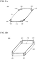
- Fig. 1A is a perspective view showing an example of the blank 100 according to the embodiment.
- Fig. 1B is a perspective view showing an example of a formed product 200 according to the embodiment.
- the blank 100 according to the embodiment is a material to be processed which is subjected to various processing so that the material to be processed is finally processed into a formed product having a prescribed shape.
- the blank 100 is formed to have a prescribed sheet shape through cutting processing from, for example, a steel sheet which is a flat sheet-shaped member. Examples of the cutting processing include known cutting processing techniques such as punching press processing and laser processing and are not particularly limited.
- the blank 100 cut out from the steel sheet is processed into a formed product having a prescribed shape through, for example, cold forming.
- the blank 100 is processed to have a shape in which the blank 100 has a shrinkage flange portion (corresponding to a shrinkage flange portion 221 in Fig. 1B which will be described later) through cold forming.
- the cold forming include known cold forming techniques such as press bending processing and press drawing processing and are not particularly limited.
- the blank 100 has a main portion region 110 and protruding regions 113.
- the main portion region 110 is a region mainly constituting the blank 100 and has the same properties as the steel sheet from which the blank 100 is cut out.
- the main portion region 110 may be a steel having a tensile strength of 1100 MPa or more.
- the main portion region 110 may be a steel having a tensile strength of 1100 MPa or more and 2000 MPa or less.
- the protruding regions 113 are regions in which a part of an outer edge 111 in the blank 100 protrudes outward when viewed in a plan view substantially perpendicular to the sheet surface of the blank 100, that is, in in-plane directions of the blank 100. Furthermore, the protruding regions 113 are regions which are shrinkage flange portions after forming. In other words, at least a part of the formed protruding regions 113 constitute at least a part of the shrinkage flange portion. Softened parts 120 are formed at least partially in the protruding regions 113. Details of the softened parts 120 will be described later.
- the blank 100 may have two or more protruding regions 113 having the softened parts 120 formed therein.
- the blank 100 having a prescribed shape is formed into the formed product 200 having a prescribed shape through, for example, cold forming.
- the formed product 200 has a box shape and has a web portion 210 as a bottom surface, a flange portion 220 standing upright from the bottom surface, and the shrinkage flange portion 221.
- the formed product 200 includes a finished product formed to have a prescribed shape by processing the blank 100 and a semi-finished product in which steps such as additional processing and treatments are required.
- the formed product 200 has the flange portion 220 formed by bending an outer circumferential side of the blank 100.
- the flange portion 220 has the shrinkage flange portion 221 deforming while a part thereof receives compressive stress during forming.
- the appearance and the dimensional accuracy of the formed product 200 easily deteriorate and the welding quality thereof easily deteriorates.
- the base steel sheet of the blank 100 is a steel having a tensile strength of 1100 MPa or more, an influence of the occurrence of wrinkles increases.
- the inventors of the present invention have conceived the idea of forming the softened parts 120 in the protruding regions 113 of the blank 100 corresponding to the shrinkage flange portion 221 of the formed product 200. That is to say, the inventors of the present invention have come up with the idea of forming the softened parts 120 in the protruding regions 113 to reduce a yield point of a region which is the shrinkage flange portion 221, minimize out-of-plane deformation during forming, and minimize the occurrence of wrinkles in the shrinkage flange portion 221.
- the Vickers hardness of a shrinkage flange portion differs in a ridgeline direction. Furthermore, a difference occurs in a sheet thickness of the shrinkage flange portion in the ridgeline direction.
- the shrinkage flange portion is different from, for example, a bent part in a formed product obtained by bending a sheet material in an out-of-plane direction.
- the ridgeline direction of the flange portion can be also referred to as a direction parallel to a line of intersection of virtual planes in which sheet surfaces of two flange portions adjacent to the shrinkage flange portion expand.
- the Vickers hardness of the shrinkage flange portion 221 increases and the sheet thickness of the shrinkage flange portion 221 further increases as a distance from the web portion 210 increases in the ridgeline direction of the shrinkage flange portion 221.
- the softened parts 120 are softened regions formed at least partially in the protruding regions 113 of the blank 100.
- the Vickers hardness of the softened parts 120 is set lower than the Vickers hardness of the main portion region 110 of the blank 100.
- the Vickers hardness of the softened parts 120 may be set to be 0.4 or more and 0.9 or less as a proportion with respect to the Vickers hardness of the main portion region 110 of the blank 100.
- the Vickers hardness of the softened parts 120 is set to 0.9 or less of the Vickers hardness of the main portion region 110, the effect of minimizing the occurrence of wrinkles in the shrinkage flange portion 221 of the formed product can be obtained by partially reducing the yield point of the protruding regions 113.
- it is possible to maintain a sufficient strength of the formed product by setting the Vickers hardness of the softened parts 120 to 0.4 or more with respect to the Vickers hardness of the main portion region 110.
- the hardness measurement conditions are as follows. A sample including the protruding regions 113 of the blank 100 is collected, a sample of a measurement surface is prepared, and the sample is subjected to a Vickers hardness test. A method for preparing a measurement surface is performed conforming to JIS Z 2244:2009. After the measurement surface is polished using #600 to #1500 silicon carbide paper, the measurement surface is mirror-finished using a liquid obtained by dispersing a diamond powder having a particle size of 1 ⁇ m to 6 ⁇ m in a diluting solution such as alcohol and pure water. The Vickers hardness test is performed in accordance with the method described in JIS Z 2244: 2009.
- the Vickers hardness of a sample having a measurement surface prepared thereon is measured using a micro Vickers hardness tester with a test load of 1 kgf (9.8 N).
- positions in which the Vickers hardness is 0.9 or less with respect to an average value of the Vickers hardness at a plurality of positions on a central portion of the main portion region 110 may be set as the softened parts 120.
- the softened parts 120 may be set so that the tensile strength is 1000 MPa or less. Thus, the strength of the softened parts 120 is minimized and the occurrence of wrinkles is further minimized.
- Examples of the method for forming each of the softened parts 120 include a method for softening the blank 100 by partially tempering the blank 100 using a known partial heating technique such as laser heating or high frequency heating. Furthermore, as another example, the blank 100 may be softened by partially tempering the blank 100 through a hot forming technique such as partial hot forming.
- the method for forming the softened part 120 may be any method as long as the hardness can be partially reduced and may be a method other than tempering with heating. For example, the method may be a method such as partially decarburizing the blank 100.
- the softened parts 120 may not be formed in all of the protruding regions 113 included in the blank 100.
- the softened parts 120 may be formed in the protruding regions 113 in which the occurrence of wrinkles is predicted in consideration of the shape, the size, and the like of the shrinkage flange portion 221 after forming.
- the softened parts 120 may be formed in a region including the outer edge 111 of the protruding regions 113. In other words, the softened parts 120 may be formed in at least a part of the outer edge 111 of the protruding regions 113. When the softened parts 120 are formed in the region including the outer edge 111 of the protruding regions 113, the vicinity of the outer edge 111 in which wrinkles easily occur is softened and the occurrence of wrinkles can be further minimized.
- the softened parts 120 may expand in the protruding regions 113 in the in-plane directions (a direction orthogonal to a sheet thickness direction) of the blank 100.
- the softened part 120 includes the outer edge 111, may be formed in the in-plane directions over a distance from the outer edge 111 of 60 mm, and preferably may be formed over a distance from the outer edge 111 of 40 mm.
- the softened parts 120 When the softened parts 120 expand in the in-plane directions, softened regions in the protruding regions 113 are sufficiently secured and the occurrence of wrinkles in the shrinkage flange portion 221 is further minimized. Furthermore, when the softened parts 120 are formed in the in-plane directions from the outer edge 111 within a prescribed range, high strength in a formed product can be maintained while a softened region is secured. In addition, the softened parts 120 may be formed only in the protruding regions 113 or may be formed up to the main portion region 110 as long as the softened parts 120 are within a range of 50 mm outward from the protruding regions 113.
- a formation range of the softened parts 120 may be determined in consideration of an amount corresponding to the movement of the blank 100 during forming. Furthermore, a depth of the softened parts 120 in the sheet thickness direction is not particularly limited and the softened parts 120 may be formed in the sheet thickness direction.
- the softened parts 120 may be formed of a separate member made of a different material from the main portion region 110 of the blank 100.
- the Vickers hardness of the separate member may be set lower than the Vickers hardness of the main portion region 110 of the blank 100 and the separate member may be attached to the blank 100 through welding or the like to form the softened part 120.
- the separate member has a protruding shape and is the shrinkage flange portion 221 after forming the blank 100.
- the yield point of the region which is the shrinkage flange portion 221 is reduced and the out-of-plane deformation during forming is minimized. That is to say, when the softened parts 120 are formed, plastic deformation of the protruding regions 113 easily occurs and the protruding regions 113 and the mold fit each other at an early stage after the start of forming. As a result, the out-of-plane deformation of the shrinkage flange portion 221 is minimized. Therefore, as a result of minimizing the occurrence of wrinkles on the shrinkage flange portion 221 of the formed product 200, the influence of wrinkles on the formed product 200 is reduced. Particularly, deterioration of an appearance or dimensional accuracy of the shrinkage flange portion 221 of the formed product 200 is reduced.
- a blank 300 according to a second embodiment of the present invention will be described below.
- the blank 300 according to the present embodiment is different from that of the first embodiment in that the blank is formed on a seat cushion frame by forming. Description of constituent elements in the description of the present embodiment that are the same as those of the first embodiment will be omitted.
- Fig. 2A is a plan view showing an example of the blank 300 according to the present embodiment.
- Fig. 2B is a perspective view showing an example of the seat cushion frame 400 according to the present embodiment.
- the blank 300 cut out from a steel sheet is further processed into the seat cushion frame 400 (a side frame) which is a formed product having a prescribed shape by cold forming.
- the blank 300 is processed to have a shape having a shrinkage flange portion (corresponding to a shrinkage flange portion 421 in Fig. 2B which will be described later) by cold forming such as press bending processing and press drawing processing.
- the seat cushion frame 400 is a part of a seat frame which is an internal skeleton of a vehicle seat and is a member provided on a side of a seat cushion which supports the thighs or the buttocks of a seat occupant.
- the blank 300 has a main portion region 310 and protruding regions 313.
- Each of the protruding regions 313 is a region in which a part of an outer edge 311 of the blank 300 protrudes outward when viewed in a plan view substantially perpendicular to the sheet surface of the blank 300, that is, in an in-plane direction of the blank 300.
- the protruding region 313 is a region which is a shrinkage flange portion after forming. In other words, at least a part of the formed protruding region 313 constitutes at least a part of the shrinkage flange portion.
- Softened parts 320 are formed in the protruding regions 313.
- the seat cushion frame 400 has a frame main body part 410 and a frame flange portion 420 standing upright from an end portion of the frame main body part 410.
- the frame flange portion 420 has the shrinkage flange portion 421.
- the seat cushion frame 400 can have various shapes in accordance with a structure of the seat frame.
- the seat cushion frame 400 has the frame flange portion 420 formed by bending an outer circumferential side of the blank 300.
- the shrinkage flange portion 421 is formed on the frame flange portion 420.
- wrinkles may also occur in the shrinkage flange portion 421 of the seat cushion frame 400 in some cases.
- the plurality of protruding regions 313 can be formed on the blank 300. Furthermore, the protruding regions 313 can have various protruding shapes in consideration of a shape of the seat cushion frame 400 after forming.
- the protruding regions 313 according to the present embodiment will be described below with reference to Fig. 3 .
- Fig. 3 is a diagram for explaining the protruding regions 313 of the blank 300 and is an enlarged diagram of a region X in Fig. 2A .
- the protruding region 313 is a region in which a part of the outer edge 311 of the blank 300 protrudes outward.
- the protruding region 313 is determined with a known circulation method from the setting of a circular arc parallel to the sheet surface of the blank 300 in the outer edge 311 of the blank 300 and from a radius of curvature and an opening angle of the circular arc.
- the circular arc is a circular arc connecting three points separated by a pitch of 1 mm along the outer edge 311. As shown in Fig.
- a radius of curvature R of a circular arc for determining the protruding region 313 is 150 mm or less and an opening angle ⁇ is 60 degrees or more and 120 degrees or less.
- the protruding regions 313 are specifically identified and the softened parts 320 are formed in the protruding regions 313, it is possible to provide the softened parts 320 in the protruding regions 313 in which wrinkles are assumed to occur. Thus, it is possible to effectively minimize the occurrence of wrinkles in the shrinkage flange portion 421 of the seat cushion frame 400 and maintain a high strength of the seat cushion frame 400 after forming.
- the blank 300 may have two or more protruding regions 313 having the softened parts 320 formed therein. Furthermore, the main portion region 310 of the blank 300 may be a steel having a tensile strength of 1100 MPa or more. In addition, the main portion region 310 of the blank 300 may be a steel having a tensile strength of 1100 MPa or more and 2000 MPa or less.
- the yield point of the region which is the shrinkage flange portion 421 is reduced and out-of-plane deformation during forming is minimized.
- the occurrence of wrinkles in the shrinkage flange portion 421 is minimized.
- deterioration of an appearance or dimensional accuracy of the shrinkage flange portion 421 of the seat cushion frame 400 is reduced.
- a seat cushion frame may be used as long as the seat cushion frame is a formed product having a shrinkage flange portion and the present invention is not limited to the seat cushion frame.
- the present invention may be applied to a seat back frame.
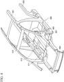
- Fig. 4 is a diagram showing an automobile skeleton 500 as an example to which a skeleton member formed using the blank 100 or 300 according to the embodiment of the present invention is applied.
- the skeleton member formed using the blank 100 or 300 can constitute the automobile skeleton 500 as a cabin skeleton or a shock absorbing skeleton.
- Examples of application as the cabin skeleton include a roof side rail 501, an A pillar lower 507, an A pillar upper 505, a kick reinforce 511, a floor cross member 513, a front header 515, and the like.
- examples of application of the skeleton member as the shock absorbing skeleton include a rear side member 503, a bumper reinforce 509, and the like.
- the skeleton member formed using the blank 100 or 300 according to any of the embodiments of the present invention minimizes the occurrence of wrinkles in the shrinkage flange portion. Thus, an influence of wrinkles is also reduced on the skeleton member.
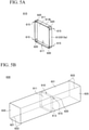
- Fig. 5A is a diagram showing an example of a component formed using the blank 100 according to the embodiment.
- Fig. 5B is a diagram showing an example in which a component formed using the blank 100 according to the embodiment is applied.
- Examples of the component formed using the blank 100 according to the embodiment include a bulkhead 610.
- the bulkhead 610 is a substantially box-shaped member in which one surface is open. When the bulkhead 610 forms a partition wall inside a hollow skeleton member, the rigidity and the collision performance of the skeleton member are further improved.
- the bulkhead 610 as a component has a box shape as an example and has a web portion 611 as a bottom surface portion, a flange portion 613 as a vertical wall portion standing upright from an end portion of the bottom surface portion, and corner portions 615. Softened parts 620 are formed at least partially on the corner portions 615. Furthermore, the web portion 611 and the flange portion 613 are composed of a main portion region 617.
- the flange portion 613 has a first flange portion 613a as a first vertical wall portion and a second flange portion 613b as a second vertical wall portion.
- Each of the corner portions 615 is provided between the first flange portion 613a and the second flange portion 613b so as to bend and connect the first flange portion 613a and the second flange portion 613b.
- the second flange portion 613b is provided in a direction substantially orthogonal to the first flange portion 613a from an end portion of the corner portion 615. Furthermore, one end of the corner portion 615 in a ridgeline direction is connected to the web portion 611.
- At least two corner portions 615 are formed on the bulkhead 610. Furthermore, the bulkhead 610 has two or more corner portions 615 having the softened part 620 formed therein. A part of the corner portion 615 is formed as a part of the shrinkage flange portion described above.
- the Vickers hardness of the softened part 620 is set lower than the Vickers hardness of the main portion region 617 constituting the web portion 611 or the flange portion 613 of the bulkhead 610. Particularly, the Vickers hardness of the softened part 620 may be set to 0.4 or more and 0.9 or less in proportion to the Vickers hardness of the main portion region 617 of the bulkhead 610.
- the Vickers hardness of the softened part 620 is set to 0.9 or less with respect to the Vickers hardness of the main portion region 617, it is possible to obtain the effect of minimizing breakage at the time of collision at the corner portion 615 of the formed product. Furthermore, when the Vickers hardness of the softened part 620 is set to 0.9 or less with respect to the Vickers hardness of the main portion region 617, it is also possible to obtain the effect of minimizing the occurrence of wrinkles. On the other hand, when the Vickers hardness of the softened part 620 is set to 0.4 or more with respect to the Vickers hardness of the main portion region, it is possible to sufficiently maintain the strength of the formed product.
- the main portion region 617 of the bulkhead 610 may be a steel having a tensile strength of 1100 MPa or more. Furthermore, the softened parts 620 may be set to have a tensile strength of 1000 MPa or less.
- the bulkhead 610 is provided inside the angular tubular skeleton member 630 in a short direction of the skeleton member 630.
- the skeleton member 630 has a pair of first wall portions 631, corner portions 633 provided on end portions of the first wall portions 631 in the short direction, and a pair of second wall portions 635 provided in a direction orthogonal to the first wall portions 631 from the corner portions 633.
- the flange portion 613 of the bulkhead 610 is attached to inner surface sides of the first wall portions 631 and the second wall portions 635.
- the corner portion 615 of the bulkhead 610 is attached to bent inner sides of the corner portions 633 of the skeleton member 630.
- the bulkhead 610 is formed of the blank 100 according to the present embodiment and the softened parts 620 are provided in the corner portion 615 of the bulkhead 610. For this reason, when a load is input to the skeleton member 630, it is possible to prevent a breakage of the bulkhead 610 in which the corner portion 615 which is a shrinkage flange portion is a starting point.
- the bulkhead 610 is formed of the blank 100 according to the present embodiment, the occurrence of wrinkles is minimized in the corner portion 615 which is a shrinkage flange portion.
- an influence of wrinkles on the bulkhead 610 is reduced, for example, the adhesion between the bulkhead 610 and the skeleton member 630 is improved.
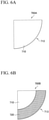
- Fig. 6A is a blank model used in the simulation analysis as Comparative Example 1.
- Fig. 6B is a blank model used in simulation analysis as an example.
- Fig. 6C is a diagram showing an example of a mold for press working assumed in the simulation analysis.
- Fig. 6D is a simple mold model in which a corner portion which forms a shrinkage flange portion is extracted from the mold shown in Fig. 6C . This analysis was performed using the simple mold model shown in Fig. 6D .
- a blank model 700A having a quadrant shape (corresponding to a protruding region) was used.
- a region 710 corresponding to a steel having a tensile strength of 1180 MPa which is a base steel sheet is provided and a radius of curvature R of an outer edge 713 when viewed in a top view was 120 mm.
- a quadrant-shaped blank model 700B was used as same as in the comparative example.
- a region 720 which is a softened part was provided on an outer circumferential side of the quadrant and the region 710 corresponding to a steel having a tensile strength of 1180 MPa which is a base steel sheet was further provided on a central side of the quadrant.
- the simulation was performed by changing the Vickers hardness of the region 720.
- the Vickers hardness of the region 720 corresponding to a softened part was set to 0.83 with respect to the Vickers hardness of the region 710. This corresponds to a case in which the softened part is a steel having a tensile strength of 980 MPa.
- the Vickers hardness of the region 720 was set to 0.66 with respect to the region 710. This corresponds to a case in which the softened part is a steel having a tensile strength of 780 MPa.
- the Vickers hardness of the region 720 was set to 0.5 with respect to the Vickers hardness of the region 710.
- the softened part is a steel having a tensile strength of 590 MPa.
- a radius of curvature R of the outer edge 713 of the model in the example when viewed in a top view is 120 mm as same as in Comparative Example 1.
- the region 720 corresponding to the softened part includes the outer edge 713 of the model and exists to a position 60 mm away from the outer edge 713 of the model. For this reason, the entire vertical wall is composed of the region 720.
- a sheet thickness of the model is the same in the example and Comparative Example 1.
- the simulation of press working of a blank was performed using mold models A', B', and C'.
- the mold models A', B', and C' are simple models corresponding to parts of a die A, a pad B, a punch C in Fig. 6C respectively.
- the inventors of the present invention deformed the blank model by moving the blank model toward the mold model A' (the die) while holding the central side using the mold model C' (the punch) and the mold model B' (the pad). That is to say, simulation analysis in which a formed product shape having a shrinkage flange portion is provided was performed by subjecting an outer circumferential side of the quadrant shape described in Figs.
- sheet thickness reduction rate indicates a reduction rate of a sheet thickness after forming with respect to the sheet thickness before forming in the shrinkage flange portion.
- a maximum value of the sheet thickness reduction rate in the formed product was defined as a sheet thickness reduction rate.
- Fig. 7 is a graph showing a sheet thickness reduction rate in a shrinkage flange portion of the model after press forming which has been obtained as a result of simulation analysis.
- sheet thickness reduction rates in Examples 1 to 3 were 16 to 18% as compared with the sheet thickness reduction rate in the comparative example.
- the sheet thickness reduction rate in the shrinkage flange portion can be reduced using the blank according to any of the embodiments of the present invention.
- the ratio of the Vickers hardness of the softened part with respect to the Vickers hardness of the main portion region was 0.9 or less, the sheet thickness reduction rate could be significantly reduced.
- the reduction of the sheet thickness reduction rate shows that the change in the sheet thickness after forming in the shrinkage flange portion is minimized, and as a result, the occurrence of wrinkles due to the change in the sheet thickness was minimized. That is to say, the blank according to any of the embodiments of the present invention was able to minimize the occurrence of wrinkles in a formed product having a shrinkage flange portion.
- the Vickers hardness ratio of the softened part with respect to the Vickers hardness of the main portion region is preferably 0.9 or less from the viewpoint of minimizing wrinkles. Furthermore, from the viewpoint of the effect of minimizing wrinkles and the strength of components, it is preferable that a ratio of the Vickers hardness of the softened part with respect to the Vickers hardness of the main portion region be 0.4 or more.
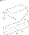
- FIG. 8 is a diagram for explaining the three-point bending crushing test conditions.
- an impactor I was made to collide with the skeleton member 630 including the bulkhead 610 according to the present invention in a direction of the arrow in Fig. 8 and the presence or absence of breakage of the corner portion 615 of the bulkhead 610 was evaluated.
- the collision position was substantially a central position of the skeleton member 630 in a longitudinal direction which is a position in which the bulkhead 610 is provided.
- the collision speed was 64 km/h and the presence or absence of breakage when an amount of impactor I to enter the skeleton member 630 was 10 mm was examined.
- Example 4 the main portion region 617 of the bulkhead 610 was made of a steel having a tensile strength of 1180 MPa. Furthermore, the strength of the softened part 620 provided on the corner portion 615 was controlled so that the tensile strength was 980 MPa, that is, it was 0.83 of the Vickers hardness of the main portion region 617. In Comparative Example 2, the softened part is not provided on the corner portion and the entire bulkhead was made of a steel having a tensile strength of 1180 MPa.
- a dimension of the skeleton member 630 was an angular tubular shape of 100 mm in a vertical direction and 100 mm in a lateral direction when viewed in a cross-sectional view in a short direction and a sheet thickness was 0.8 mm. Moreover, a sheet thickness of the bulkhead was also set to 0.8 mm. Table 1 shows the evaluation results. [Table 1] Sample Softened part of corner portion Breakage of corner portion at time of entering by 10 mm Comparative Example 2 Absence Presence Example 4 Presence Absence
- the present invention is industrially useful because the present invention can provide a blank capable of minimizing an influence of wrinkles occurring on a shrinkage flange portion or the like.
Landscapes
- Engineering & Computer Science (AREA)
- Mechanical Engineering (AREA)
- Chemical & Material Sciences (AREA)
- Materials Engineering (AREA)
- Thermal Sciences (AREA)
- Crystallography & Structural Chemistry (AREA)
- Physics & Mathematics (AREA)
- Metallurgy (AREA)
- Organic Chemistry (AREA)
- Aviation & Aerospace Engineering (AREA)
- Transportation (AREA)
- Shaping Metal By Deep-Drawing, Or The Like (AREA)
- Braking Arrangements (AREA)
Abstract
Description
- The present invention relates to a blank and a component.
- Priority is claimed on
Japanese Patent Application No. 2019-074618, filed April 10, 2019 - When a blank is processed to form a formed product having a prescribed shape, the blank may be subjected to various treatments to adjust the properties and the functions of the blank in some cases.
-
Patent Document 1 discloses a technique for ensuring the ductility of a stretched flange portion by performing partial irradiation of a laser and softening when a weld line is disposed in a region having a concave shape which is a stretched flange portion after forming, in a composite blank. - Also,
Patent Document 2 discloses a technique for partially softening a region which is a ridgeline portion in a member having a hat-shaped cross section after forming in a blank. -
- [Patent Document 1]
Japanese Unexamined Patent Application, First Publication No. H06-226479 - [Patent Document 2]
Japanese Unexamined Patent Application, First Publication No. 2011-068979 - However, in all of the above documents, problems in a shrinkage flange portion formed through compression deformation are not considered. The technique described in
Patent Document 1 is for ensuring the ductility of the stretched flange portion formed through tensile deformation due to partial softening and problems in the shrinkage flange portion formed through compression deformation are not considered. - Also, the technique described in
Patent Document 2 is also for improving the bendability of the ridgeline portion having a hat-shaped cross section after forming through partial softening and problems in the shrinkage flange portion are not considered. Particularly, in the techniques described inPatent Documents - The present invention was made in view of the above problems, and an object of the present invention is to provide a new and improved blank capable of minimizing an influence of wrinkles produced in a shrinkage flange portion or the like.
-
- (1) According to an aspect of the present invention, a blank made of a steel and including at least two protruding regions having an outer edge protruding outward in in-plane directions, in which a softened part is formed at least partially in the protruding regions and the softened part is formed in at least a part of the outer edge of the protruding regions, a Vickers hardness of the softened part is lower than a Vickers hardness of a main portion region, and the blank comprises at least two of the protruding regions having the softened part.
- (2) In the blank of the above (1), in the protruding region having the softened part formed therein, a radius of curvature R of an outer edge of the protruding region may be 150 mm or less, and an opening angle of the outer edge may be 120° or less.
- (3) In the blank of the above (1) or (2), a tensile strength of the main portion region of the blank may be 1100 MPa or more.
- (4) In the blank of any one of the above (1) to (3), a tensile strength of the softened part may be 1000 MPa or less.
- (5) In the blank of any one of the above (1) to (4), a ratio of the Vickers hardness of the softened part to the Vickers hardness of the main portion region of the blank may be 0.4 or more and 0.9 or less.
- (6) According to another aspect of the present invention, a component made of a steel and including: a bottom surface portion; a first vertical wall portion and a second vertical wall portion which stand upright from an end portion of the bottom surface portion; and at least two corner portions provided between the first vertical wall portion and the second vertical wall portion, in which a softened part is formed at least partially in the corner portion, a Vickers hardness of the softened part is lower than a Vickers hardness of a main portion region of the component, and the component includes at least two of the corner portions having the softened part.
- (7) In the component of the above (6), a tensile strength of the main portion region of the component may be 1100 MPa or more.
- (8) In the component of the above (6) or (7), a tensile strength of the softened part may be 1000 MPa or less.
- (9) In the component of any one of the above (6) to (8), a ratio of the Vickers hardness of the softened part to the Vickers hardness of the component may be 0.4 or more and 0.9 or less.
- (10) In the component of any one of the above (6) to (9), the corner portion may include a shrinkage flange portion.
- According to the present invention, a new and improved blank capable of minimizing an influence of wrinkles produced in a shrinkage flange portion or the like is provided.
-
-
Fig. 1A is a perspective view showing an example of a blank according to a first embodiment of the present invention. -
Fig. 1B is a perspective view showing an example of a formed product according to the embodiment. -
Fig. 2A is a plan view showing an example of a blank according to a second embodiment of the present invention. -
Fig. 2B is a perspective view showing an example of a seat cushion frame according to the embodiment. -
Fig. 3 is a cross-sectional view showing protruding regions according to the second embodiment of the present invention. -
Fig. 4 shows an automobile skeleton as an example to which a skeleton member formed using a blank according to any embodiment of the present invention is applied. -
Fig. 5A shows an example of a component formed using a blank according to any embodiment of the present invention. -
Fig. 5B shows an example to which a component formed using a blank according to any embodiment of the present invention is applied. -
Fig. 6A shows a blank model used for simulation analysis as a comparative example. -
Fig. 6B shows a blank model used for simulation analysis as an example. -
Fig. 6C shows an example of a press working form assumed in simulation analysis. -
Fig. 6D shows a simple mold model in which a shrinkage flange portion of a mold model for press working assumed in simulation analysis is extracted. -
Fig. 7 is a graph showing a sheet thickness reduction rate obtained as a result of simulation analysis. -
Fig. 8 is a diagram for explaining three-point bending crushing test conditions. - Preferred embodiments of the present invention will be described in detail below with reference to the accompanying drawings. In the specification and the drawings, constituent elements having substantially the same functional constitution are denoted by the same reference numerals and duplicate description thereof will be omitted.
- First, a schematic configuration of a blank 100 according to a first embodiment of the present invention will be described with reference to
Figs. 1A and 1B. Fig. 1A is a perspective view showing an example of the blank 100 according to the embodiment.Fig. 1B is a perspective view showing an example of a formedproduct 200 according to the embodiment. The blank 100 according to the embodiment is a material to be processed which is subjected to various processing so that the material to be processed is finally processed into a formed product having a prescribed shape. The blank 100 is formed to have a prescribed sheet shape through cutting processing from, for example, a steel sheet which is a flat sheet-shaped member. Examples of the cutting processing include known cutting processing techniques such as punching press processing and laser processing and are not particularly limited. - The blank 100 cut out from the steel sheet is processed into a formed product having a prescribed shape through, for example, cold forming. Although the details of a shape of the blank 100 which has been subjected to the processing will be described later, the blank 100 is processed to have a shape in which the blank 100 has a shrinkage flange portion (corresponding to a
shrinkage flange portion 221 inFig. 1B which will be described later) through cold forming. Examples of the cold forming include known cold forming techniques such as press bending processing and press drawing processing and are not particularly limited. - As shown in
Fig. 1A , the blank 100 has amain portion region 110 and protrudingregions 113. Themain portion region 110 is a region mainly constituting the blank 100 and has the same properties as the steel sheet from which the blank 100 is cut out. Themain portion region 110 may be a steel having a tensile strength of 1100 MPa or more. Furthermore, themain portion region 110 may be a steel having a tensile strength of 1100 MPa or more and 2000 MPa or less. - The protruding
regions 113 are regions in which a part of anouter edge 111 in the blank 100 protrudes outward when viewed in a plan view substantially perpendicular to the sheet surface of the blank 100, that is, in in-plane directions of the blank 100. Furthermore, the protrudingregions 113 are regions which are shrinkage flange portions after forming. In other words, at least a part of the formed protrudingregions 113 constitute at least a part of the shrinkage flange portion.Softened parts 120 are formed at least partially in the protrudingregions 113. Details of the softenedparts 120 will be described later. The blank 100 may have two or moreprotruding regions 113 having the softenedparts 120 formed therein. - A shape of the formed
product 200 and problems during forming will be described below with reference toFig. 1B . The blank 100 having a prescribed shape is formed into the formedproduct 200 having a prescribed shape through, for example, cold forming. As shown inFig. 1B , for example, the formedproduct 200 has a box shape and has aweb portion 210 as a bottom surface, aflange portion 220 standing upright from the bottom surface, and theshrinkage flange portion 221. Here, the formedproduct 200 includes a finished product formed to have a prescribed shape by processing the blank 100 and a semi-finished product in which steps such as additional processing and treatments are required. - For example, the formed
product 200 has theflange portion 220 formed by bending an outer circumferential side of the blank 100. Theflange portion 220 has theshrinkage flange portion 221 deforming while a part thereof receives compressive stress during forming. - In such a formed product having the
shrinkage flange portion 221, problems due to the shape thereof may arise in some cases. That is to say, due to the compressive stress during forming, a part of the blank 100 (the protruding regions 113) may deform in a wavy shape as a result of out-of-plane deformation during forming. When the deformed position is further crushed with a mold, after forming, wrinkles which are minute unevennesses occur. Wrinkles occurring in a formed product may cause deterioration of an appearance or dimensional accuracy of the formed product or deterioration of welding quality. - Particularly, when a high-strength steel sheet is used as a base steel sheet of the blank 100, formability is reduced, since such a steel has a high yield stress and an inferior ductility. Furthermore, since high-strength steel sheets may be used for the purpose of weight reduction in many cases and are thinned, surface rigidity is reduced as a steel sheet. Due to these causes, when the formed
product 200 having theshrinkage flange portion 221 is formed using the blank 100 of a high-strength steel sheet, wrinkles after forming are likely to occur on theshrinkage flange portion 221 and a height of wrinkles and an amount of increase in thickness of wrinkles also increase. As a result, the appearance and the dimensional accuracy of the formedproduct 200 easily deteriorate and the welding quality thereof easily deteriorates. Particularly, when the base steel sheet of the blank 100 is a steel having a tensile strength of 1100 MPa or more, an influence of the occurrence of wrinkles increases. - Thus, as a result of diligent studies, the inventors of the present invention have conceived the idea of forming the
softened parts 120 in the protrudingregions 113 of the blank 100 corresponding to theshrinkage flange portion 221 of the formedproduct 200. That is to say, the inventors of the present invention have come up with the idea of forming thesoftened parts 120 in the protrudingregions 113 to reduce a yield point of a region which is theshrinkage flange portion 221, minimize out-of-plane deformation during forming, and minimize the occurrence of wrinkles in theshrinkage flange portion 221. - Due to the forming process described above, the Vickers hardness of a shrinkage flange portion differs in a ridgeline direction. Furthermore, a difference occurs in a sheet thickness of the shrinkage flange portion in the ridgeline direction. In this respect, the shrinkage flange portion is different from, for example, a bent part in a formed product obtained by bending a sheet material in an out-of-plane direction. The ridgeline direction of the flange portion can be also referred to as a direction parallel to a line of intersection of virtual planes in which sheet surfaces of two flange portions adjacent to the shrinkage flange portion expand.
- For example, in the
shrinkage flange portion 221 of the formedproduct 200 illustrated inFig. 1B , the Vickers hardness of theshrinkage flange portion 221 increases and the sheet thickness of theshrinkage flange portion 221 further increases as a distance from theweb portion 210 increases in the ridgeline direction of theshrinkage flange portion 221. - The softened
parts 120 are softened regions formed at least partially in the protrudingregions 113 of the blank 100. The Vickers hardness of the softenedparts 120 is set lower than the Vickers hardness of themain portion region 110 of the blank 100. Particularly, the Vickers hardness of the softenedparts 120 may be set to be 0.4 or more and 0.9 or less as a proportion with respect to the Vickers hardness of themain portion region 110 of the blank 100. - When the Vickers hardness of the softened
parts 120 is set to 0.9 or less of the Vickers hardness of themain portion region 110, the effect of minimizing the occurrence of wrinkles in theshrinkage flange portion 221 of the formed product can be obtained by partially reducing the yield point of the protrudingregions 113. On the other hand, it is possible to maintain a sufficient strength of the formed product by setting the Vickers hardness of the softenedparts 120 to 0.4 or more with respect to the Vickers hardness of themain portion region 110. - The hardness measurement conditions are as follows. A sample including the protruding
regions 113 of the blank 100 is collected, a sample of a measurement surface is prepared, and the sample is subjected to a Vickers hardness test. A method for preparing a measurement surface is performed conforming to JIS Z 2244:2009. After the measurement surface is polished using #600 to #1500 silicon carbide paper, the measurement surface is mirror-finished using a liquid obtained by dispersing a diamond powder having a particle size of 1 µm to 6 µm in a diluting solution such as alcohol and pure water. The Vickers hardness test is performed in accordance with the method described in JIS Z 2244: 2009. The Vickers hardness of a sample having a measurement surface prepared thereon is measured using a micro Vickers hardness tester with a test load of 1 kgf (9.8 N). For example, positions in which the Vickers hardness is 0.9 or less with respect to an average value of the Vickers hardness at a plurality of positions on a central portion of themain portion region 110 may be set as thesoftened parts 120. - Also, the softened
parts 120 may be set so that the tensile strength is 1000 MPa or less. Thus, the strength of the softenedparts 120 is minimized and the occurrence of wrinkles is further minimized. - Examples of the method for forming each of the softened
parts 120 include a method for softening the blank 100 by partially tempering the blank 100 using a known partial heating technique such as laser heating or high frequency heating. Furthermore, as another example, the blank 100 may be softened by partially tempering the blank 100 through a hot forming technique such as partial hot forming. The method for forming thesoftened part 120 may be any method as long as the hardness can be partially reduced and may be a method other than tempering with heating. For example, the method may be a method such as partially decarburizing the blank 100. - The softened
parts 120 may not be formed in all of the protrudingregions 113 included in the blank 100. The softenedparts 120 may be formed in the protrudingregions 113 in which the occurrence of wrinkles is predicted in consideration of the shape, the size, and the like of theshrinkage flange portion 221 after forming. - The softened
parts 120 may be formed in a region including theouter edge 111 of the protrudingregions 113. In other words, the softenedparts 120 may be formed in at least a part of theouter edge 111 of the protrudingregions 113. When the softenedparts 120 are formed in the region including theouter edge 111 of the protrudingregions 113, the vicinity of theouter edge 111 in which wrinkles easily occur is softened and the occurrence of wrinkles can be further minimized. - Also, the softened
parts 120 may expand in the protrudingregions 113 in the in-plane directions (a direction orthogonal to a sheet thickness direction) of the blank 100. To be specific, thesoftened part 120 includes theouter edge 111, may be formed in the in-plane directions over a distance from theouter edge 111 of 60 mm, and preferably may be formed over a distance from theouter edge 111 of 40 mm. - When the softened
parts 120 expand in the in-plane directions, softened regions in the protrudingregions 113 are sufficiently secured and the occurrence of wrinkles in theshrinkage flange portion 221 is further minimized. Furthermore, when the softenedparts 120 are formed in the in-plane directions from theouter edge 111 within a prescribed range, high strength in a formed product can be maintained while a softened region is secured. In addition, the softenedparts 120 may be formed only in the protrudingregions 113 or may be formed up to themain portion region 110 as long as thesoftened parts 120 are within a range of 50 mm outward from the protrudingregions 113. - In the case of press working (drawing forming, bending forming) in which the movement of the blank 100 can occur when the blank 100 is processed to have a prescribed shape, a formation range of the softened
parts 120 may be determined in consideration of an amount corresponding to the movement of the blank 100 during forming. Furthermore, a depth of the softenedparts 120 in the sheet thickness direction is not particularly limited and the softenedparts 120 may be formed in the sheet thickness direction. - Also, the softened
parts 120 may be formed of a separate member made of a different material from themain portion region 110 of the blank 100. For example, the Vickers hardness of the separate member may be set lower than the Vickers hardness of themain portion region 110 of the blank 100 and the separate member may be attached to the blank 100 through welding or the like to form thesoftened part 120. In this case, the separate member has a protruding shape and is theshrinkage flange portion 221 after forming the blank 100. - According to the embodiment, when the softened
parts 120 are formed in the protrudingregions 113, the yield point of the region which is theshrinkage flange portion 221 is reduced and the out-of-plane deformation during forming is minimized. That is to say, when the softenedparts 120 are formed, plastic deformation of the protrudingregions 113 easily occurs and the protrudingregions 113 and the mold fit each other at an early stage after the start of forming. As a result, the out-of-plane deformation of theshrinkage flange portion 221 is minimized. Therefore, as a result of minimizing the occurrence of wrinkles on theshrinkage flange portion 221 of the formedproduct 200, the influence of wrinkles on the formedproduct 200 is reduced. Particularly, deterioration of an appearance or dimensional accuracy of theshrinkage flange portion 221 of the formedproduct 200 is reduced. - A blank 300 according to a second embodiment of the present invention will be described below. The blank 300 according to the present embodiment is different from that of the first embodiment in that the blank is formed on a seat cushion frame by forming. Description of constituent elements in the description of the present embodiment that are the same as those of the first embodiment will be omitted.
- The blank 300 and a
seat cushion frame 400 according to the present embodiment will be described with reference toFigs. 2A and 2B. Fig. 2A is a plan view showing an example of the blank 300 according to the present embodiment.Fig. 2B is a perspective view showing an example of theseat cushion frame 400 according to the present embodiment. - The blank 300 cut out from a steel sheet is further processed into the seat cushion frame 400 (a side frame) which is a formed product having a prescribed shape by cold forming. To be specific, the blank 300 is processed to have a shape having a shrinkage flange portion (corresponding to a
shrinkage flange portion 421 inFig. 2B which will be described later) by cold forming such as press bending processing and press drawing processing. Theseat cushion frame 400 is a part of a seat frame which is an internal skeleton of a vehicle seat and is a member provided on a side of a seat cushion which supports the thighs or the buttocks of a seat occupant. - As shown in
Fig. 2A , the blank 300 has amain portion region 310 and protrudingregions 313. Each of the protrudingregions 313 is a region in which a part of anouter edge 311 of the blank 300 protrudes outward when viewed in a plan view substantially perpendicular to the sheet surface of the blank 300, that is, in an in-plane direction of the blank 300. Furthermore, theprotruding region 313 is a region which is a shrinkage flange portion after forming. In other words, at least a part of the formedprotruding region 313 constitutes at least a part of the shrinkage flange portion.Softened parts 320 are formed in the protrudingregions 313. - As shown in
Fig. 2B , theseat cushion frame 400 has a framemain body part 410 and aframe flange portion 420 standing upright from an end portion of the framemain body part 410. Theframe flange portion 420 has theshrinkage flange portion 421. Theseat cushion frame 400 can have various shapes in accordance with a structure of the seat frame. - As an example, the
seat cushion frame 400 has theframe flange portion 420 formed by bending an outer circumferential side of the blank 300. When the protrudingregions 313 of the blank 300 deform while receiving compressive stress during forming, theshrinkage flange portion 421 is formed on theframe flange portion 420. As described above, wrinkles may also occur in theshrinkage flange portion 421 of theseat cushion frame 400 in some cases. - As shown in
Fig. 2A , the plurality of protrudingregions 313 can be formed on the blank 300. Furthermore, the protrudingregions 313 can have various protruding shapes in consideration of a shape of theseat cushion frame 400 after forming. The protrudingregions 313 according to the present embodiment will be described below with reference toFig. 3 . -
Fig. 3 is a diagram for explaining the protrudingregions 313 of the blank 300 and is an enlarged diagram of a region X inFig. 2A . As shown inFig. 3 , theprotruding region 313 is a region in which a part of theouter edge 311 of the blank 300 protrudes outward. Theprotruding region 313 is determined with a known circulation method from the setting of a circular arc parallel to the sheet surface of the blank 300 in theouter edge 311 of the blank 300 and from a radius of curvature and an opening angle of the circular arc. The circular arc is a circular arc connecting three points separated by a pitch of 1 mm along theouter edge 311. As shown inFig. 3 , a radius of curvature R of a circular arc for determining theprotruding region 313 is 150 mm or less and an opening angle θ is 60 degrees or more and 120 degrees or less. Through the above method, the protrudingregions 313 are determined and the softenedparts 320 are formed in the protrudingregions 313. - As described above, when the protruding
regions 313 are specifically identified and the softenedparts 320 are formed in the protrudingregions 313, it is possible to provide the softenedparts 320 in the protrudingregions 313 in which wrinkles are assumed to occur. Thus, it is possible to effectively minimize the occurrence of wrinkles in theshrinkage flange portion 421 of theseat cushion frame 400 and maintain a high strength of theseat cushion frame 400 after forming. - The blank 300 may have two or more
protruding regions 313 having the softenedparts 320 formed therein. Furthermore, themain portion region 310 of the blank 300 may be a steel having a tensile strength of 1100 MPa or more. In addition, themain portion region 310 of the blank 300 may be a steel having a tensile strength of 1100 MPa or more and 2000 MPa or less. - According to the present embodiment, when the softened
parts 320 are formed in the protrudingregions 313, the yield point of the region which is theshrinkage flange portion 421 is reduced and out-of-plane deformation during forming is minimized. As a result, in theseat cushion frame 400 which is a formed product, the occurrence of wrinkles in theshrinkage flange portion 421 is minimized. Thus, it is possible to reduce an influence of wrinkles on theseat cushion frame 400. Particularly, deterioration of an appearance or dimensional accuracy of theshrinkage flange portion 421 of theseat cushion frame 400 is reduced. - Although an example in which the blank 300 is formed in the
seat cushion frame 400 has been described in the present embodiment, a seat cushion frame may be used as long as the seat cushion frame is a formed product having a shrinkage flange portion and the present invention is not limited to the seat cushion frame. For example, the present invention may be applied to a seat back frame. - The preferred embodiments of the present invention have been described in detail above. An application example of a skeleton member formed using the blank 100 or 300 according to any of the embodiments of the present invention will be described below with reference to
Fig. 4. Fig. 4 is a diagram showing anautomobile skeleton 500 as an example to which a skeleton member formed using the blank 100 or 300 according to the embodiment of the present invention is applied. The skeleton member formed using the blank 100 or 300 can constitute theautomobile skeleton 500 as a cabin skeleton or a shock absorbing skeleton. Examples of application as the cabin skeleton include aroof side rail 501, an A pillar lower 507, an A pillar upper 505, a kick reinforce 511, afloor cross member 513, afront header 515, and the like. - Also, examples of application of the skeleton member as the shock absorbing skeleton include a
rear side member 503, a bumper reinforce 509, and the like. - The skeleton member formed using the blank 100 or 300 according to any of the embodiments of the present invention minimizes the occurrence of wrinkles in the shrinkage flange portion. Thus, an influence of wrinkles is also reduced on the skeleton member.
- An example of a component formed using the blank 100 according to any of the embodiments of the present invention will be described below with reference to
Figs. 5A and 5B. Fig. 5A is a diagram showing an example of a component formed using the blank 100 according to the embodiment. Furthermore,Fig. 5B is a diagram showing an example in which a component formed using the blank 100 according to the embodiment is applied. Examples of the component formed using the blank 100 according to the embodiment include abulkhead 610. Thebulkhead 610 is a substantially box-shaped member in which one surface is open. When thebulkhead 610 forms a partition wall inside a hollow skeleton member, the rigidity and the collision performance of the skeleton member are further improved. - As shown in
Fig. 5A , thebulkhead 610 as a component has a box shape as an example and has aweb portion 611 as a bottom surface portion, aflange portion 613 as a vertical wall portion standing upright from an end portion of the bottom surface portion, andcorner portions 615.Softened parts 620 are formed at least partially on thecorner portions 615. Furthermore, theweb portion 611 and theflange portion 613 are composed of amain portion region 617. - The
flange portion 613 has afirst flange portion 613a as a first vertical wall portion and asecond flange portion 613b as a second vertical wall portion. Each of thecorner portions 615 is provided between thefirst flange portion 613a and thesecond flange portion 613b so as to bend and connect thefirst flange portion 613a and thesecond flange portion 613b. Thesecond flange portion 613b is provided in a direction substantially orthogonal to thefirst flange portion 613a from an end portion of thecorner portion 615. Furthermore, one end of thecorner portion 615 in a ridgeline direction is connected to theweb portion 611. - As shown in
Fig. 5A , at least twocorner portions 615 are formed on thebulkhead 610. Furthermore, thebulkhead 610 has two ormore corner portions 615 having thesoftened part 620 formed therein. A part of thecorner portion 615 is formed as a part of the shrinkage flange portion described above. - The Vickers hardness of the
softened part 620 is set lower than the Vickers hardness of themain portion region 617 constituting theweb portion 611 or theflange portion 613 of thebulkhead 610. Particularly, the Vickers hardness of thesoftened part 620 may be set to 0.4 or more and 0.9 or less in proportion to the Vickers hardness of themain portion region 617 of thebulkhead 610. - When the Vickers hardness of the
softened part 620 is set to 0.9 or less with respect to the Vickers hardness of themain portion region 617, it is possible to obtain the effect of minimizing breakage at the time of collision at thecorner portion 615 of the formed product. Furthermore, when the Vickers hardness of thesoftened part 620 is set to 0.9 or less with respect to the Vickers hardness of themain portion region 617, it is also possible to obtain the effect of minimizing the occurrence of wrinkles. On the other hand, when the Vickers hardness of thesoftened part 620 is set to 0.4 or more with respect to the Vickers hardness of the main portion region, it is possible to sufficiently maintain the strength of the formed product. - The
main portion region 617 of thebulkhead 610 may be a steel having a tensile strength of 1100 MPa or more. Furthermore, the softenedparts 620 may be set to have a tensile strength of 1000 MPa or less. - The
bulkhead 610 is provided inside the angulartubular skeleton member 630 in a short direction of theskeleton member 630. Theskeleton member 630 has a pair offirst wall portions 631,corner portions 633 provided on end portions of thefirst wall portions 631 in the short direction, and a pair ofsecond wall portions 635 provided in a direction orthogonal to thefirst wall portions 631 from thecorner portions 633. Theflange portion 613 of thebulkhead 610 is attached to inner surface sides of thefirst wall portions 631 and thesecond wall portions 635. Furthermore, thecorner portion 615 of thebulkhead 610 is attached to bent inner sides of thecorner portions 633 of theskeleton member 630. - The
bulkhead 610 is formed of the blank 100 according to the present embodiment and the softenedparts 620 are provided in thecorner portion 615 of thebulkhead 610. For this reason, when a load is input to theskeleton member 630, it is possible to prevent a breakage of thebulkhead 610 in which thecorner portion 615 which is a shrinkage flange portion is a starting point. - Also, since the
bulkhead 610 is formed of the blank 100 according to the present embodiment, the occurrence of wrinkles is minimized in thecorner portion 615 which is a shrinkage flange portion. Thus, an influence of wrinkles on thebulkhead 610 is reduced, for example, the adhesion between thebulkhead 610 and theskeleton member 630 is improved. - In order to confirm an influence of the blank according to the above-described embodiment on the occurrence of wrinkles, simulation analysis of press forming was performed. The simulation analysis results will be described with reference to
Figs. 6A, 6B ,6C , and6D .Fig. 6A is a blank model used in the simulation analysis as Comparative Example 1.Fig. 6B is a blank model used in simulation analysis as an example.Fig. 6C is a diagram showing an example of a mold for press working assumed in the simulation analysis.Fig. 6D is a simple mold model in which a corner portion which forms a shrinkage flange portion is extracted from the mold shown inFig. 6C . This analysis was performed using the simple mold model shown inFig. 6D . - As shown in
Fig. 6A , in the comparative example to the present invention, ablank model 700A having a quadrant shape (corresponding to a protruding region) was used. In the comparative example, aregion 710 corresponding to a steel having a tensile strength of 1180 MPa which is a base steel sheet is provided and a radius of curvature R of anouter edge 713 when viewed in a top view was 120 mm. On the other hand, as shown inFig. 6B , in the example of the present invention, a quadrant-shapedblank model 700B was used as same as in the comparative example. In the example, aregion 720 which is a softened part was provided on an outer circumferential side of the quadrant and theregion 710 corresponding to a steel having a tensile strength of 1180 MPa which is a base steel sheet was further provided on a central side of the quadrant. - Also, in the example, the simulation was performed by changing the Vickers hardness of the
region 720. In Example 1, the Vickers hardness of theregion 720 corresponding to a softened part was set to 0.83 with respect to the Vickers hardness of theregion 710. This corresponds to a case in which the softened part is a steel having a tensile strength of 980 MPa. In Example 2, the Vickers hardness of theregion 720 was set to 0.66 with respect to theregion 710. This corresponds to a case in which the softened part is a steel having a tensile strength of 780 MPa. In Example 3, the Vickers hardness of theregion 720 was set to 0.5 with respect to the Vickers hardness of theregion 710. This corresponds to a case in which the softened part is a steel having a tensile strength of 590 MPa. A radius of curvature R of theouter edge 713 of the model in the example when viewed in a top view is 120 mm as same as in Comparative Example 1. In addition, theregion 720 corresponding to the softened part includes theouter edge 713 of the model and exists to a position 60 mm away from theouter edge 713 of the model. For this reason, the entire vertical wall is composed of theregion 720. A sheet thickness of the model is the same in the example and Comparative Example 1. - As shown in
Fig. 6D , the simulation of press working of a blank was performed using mold models A', B', and C'. The mold models A', B', and C' are simple models corresponding to parts of a die A, a pad B, a punch C inFig. 6C respectively. The inventors of the present invention deformed the blank model by moving the blank model toward the mold model A' (the die) while holding the central side using the mold model C' (the punch) and the mold model B' (the pad). That is to say, simulation analysis in which a formed product shape having a shrinkage flange portion is provided was performed by subjecting an outer circumferential side of the quadrant shape described inFigs. 6A and 6B to compression deformation while bending the outer circumferential side to form a flange. In addition, sheet thickness reduction rates which has occurred in the shrinkage flange portions of each of the models after forming were compared. Here, the sheet thickness reduction rate indicates a reduction rate of a sheet thickness after forming with respect to the sheet thickness before forming in the shrinkage flange portion. A maximum value of the sheet thickness reduction rate in the formed product was defined as a sheet thickness reduction rate. -
Fig. 7 is a graph showing a sheet thickness reduction rate in a shrinkage flange portion of the model after press forming which has been obtained as a result of simulation analysis. As shown inFig. 7 , sheet thickness reduction rates in Examples 1 to 3 were 16 to 18% as compared with the sheet thickness reduction rate in the comparative example. As a result, it was seen that the sheet thickness reduction rate in the shrinkage flange portion can be reduced using the blank according to any of the embodiments of the present invention. In addition, it was seen that, if the ratio of the Vickers hardness of the softened part with respect to the Vickers hardness of the main portion region was 0.9 or less, the sheet thickness reduction rate could be significantly reduced. - It was shown that the reduction of the sheet thickness reduction rate shows that the change in the sheet thickness after forming in the shrinkage flange portion is minimized, and as a result, the occurrence of wrinkles due to the change in the sheet thickness was minimized. That is to say, the blank according to any of the embodiments of the present invention was able to minimize the occurrence of wrinkles in a formed product having a shrinkage flange portion.
- Also, as shown in
Fig. 7 , it was seen that, since the sheet thickness reduction rate does not change significantly among Examples 1 to 3, even if a Vickers hardness ratio of the softened part was reduced from 0.9, a reduction margin of the sheet thickness reduction rate did not change significantly. That is to say, it was shown that the Vickers hardness ratio of the softened part with respect to the Vickers hardness of the main portion region is preferably 0.9 or less from the viewpoint of minimizing wrinkles. Furthermore, from the viewpoint of the effect of minimizing wrinkles and the strength of components, it is preferable that a ratio of the Vickers hardness of the softened part with respect to the Vickers hardness of the main portion region be 0.4 or more. - A three-point bending crush test was performed to evaluate the performance of the
bulkhead 610 as a component according to the present invention. The test results will be described with reference toFig. 8. Fig. 8 is a diagram for explaining the three-point bending crushing test conditions. As shown inFig. 8 , an impactor I was made to collide with theskeleton member 630 including thebulkhead 610 according to the present invention in a direction of the arrow inFig. 8 and the presence or absence of breakage of thecorner portion 615 of thebulkhead 610 was evaluated. The collision position was substantially a central position of theskeleton member 630 in a longitudinal direction which is a position in which thebulkhead 610 is provided. Furthermore, the collision speed was 64 km/h and the presence or absence of breakage when an amount of impactor I to enter theskeleton member 630 was 10 mm was examined. - In Example 4, the
main portion region 617 of thebulkhead 610 was made of a steel having a tensile strength of 1180 MPa. Furthermore, the strength of thesoftened part 620 provided on thecorner portion 615 was controlled so that the tensile strength was 980 MPa, that is, it was 0.83 of the Vickers hardness of themain portion region 617. In Comparative Example 2, the softened part is not provided on the corner portion and the entire bulkhead was made of a steel having a tensile strength of 1180 MPa. A dimension of theskeleton member 630 was an angular tubular shape of 100 mm in a vertical direction and 100 mm in a lateral direction when viewed in a cross-sectional view in a short direction and a sheet thickness was 0.8 mm. Moreover, a sheet thickness of the bulkhead was also set to 0.8 mm. Table 1 shows the evaluation results.[Table 1] Sample Softened part of corner portion Breakage of corner portion at time of entering by 10 mm Comparative Example 2 Absence Presence Example 4 Presence Absence - As shown in Table 1, in Comparative Example 2 in which the softened part was not provided on the corner portion, breakage occurred in the corner portion of the bulkhead when the impactor I entered by 10 mm. On the other hand, in Example 4, the
bulkhead 610 did not break even when the impactor I entered by 10 mm. In this way, it was shown that, when thesoftened part 620 softened more than themain portion region 617 is provided in thecorner portion 615 and the strength of thesoftened part 620 is set to 0.9 or less of the Vickers hardness of themain portion region 617, the breakage at thecorner portion 615 of thebulkhead 610 could be minimized. - Although the preferred embodiments of the present invention have been described in detail above with reference to the accompanying drawings, the present invention is not limited to such examples. It is clear that a person having ordinary knowledge in the field of technology to which the present invention belongs can come up with various changed examples or modified examples within the scope of the technical idea described in the claims and it is naturally understood that these also belong to the technical scope of the present invention.
- The present invention is industrially useful because the present invention can provide a blank capable of minimizing an influence of wrinkles occurring on a shrinkage flange portion or the like.
-
- 100, 300 Blank
- 110, 310 Main portion region
- 111, 311 Outer edge
- 113, 313 Protruding region
- 120, 320 Softened part
- 200 Formed product
- 210 Web portion
- 220 Flange portion
- 221, 421 Shrinkage flange portion
- 400 Seat cushion frame
- 610 Bulkhead (component)
- 611 Web portion (bottom surface portion)
- 613 Flange portion
- 613a First flange portion (first vertical wall portion)
- 613b Second flange portion (second vertical wall portion)
- 615 Corner portion (shrinkage flange portion)
- 617 Main portion region
- 620 Softened part
Claims (10)
- A blank made of a steel and comprising at least two protruding regions having an outer edge protruding outward in in-plane directions,wherein a softened part is formed at least partially in the protruding regions and the softened part is formed in at least a part of the outer edge of the protruding regions,a Vickers hardness of the softened part is lower than a Vickers hardness of a main portion region, andthe blank comprises at least two of the protruding regions having the softened part.
- The blank according to claim 1, wherein, in the protruding region having the softened part formed therein,a radius of curvature R of an outer edge of the protruding region is 150 mm or less, andan opening angle of the outer edge is 120° or less.
- The blank according to claim 1 or 2, wherein a tensile strength of the main portion region of the blank is 1100 MPa or more.
- The blank according to any one of claims 1 to 3, wherein a tensile strength of the softened part is 1000 MPa or less.
- The blank according to any one of claims 1 to 4, wherein a ratio of the Vickers hardness of the softened part to the Vickers hardness of the main portion region of the blank is 0.4 or more and 0.9 or less.
- A component made of a steel and comprising:a bottom surface portion;a first vertical wall portion and a second vertical wall portion which stand upright from an end portion of the bottom surface portion; andat least two corner portions provided between the first vertical wall portion and the second vertical wall portion,wherein a softened part is formed at least partially in the corner portion,a Vickers hardness of the softened part is lower than a Vickers hardness of a main portion region of the component, andthe component comprises at least two of the corner portions having the softened part.
- The component according to claim 6, wherein a tensile strength of the main portion region of the component is 1100 MPa or more.
- The component according to claim 6 or 7, wherein a tensile strength of the softened part is 1000 MPa or less.
- The component according to any one of claims 6 to 8, wherein a ratio of the Vickers hardness of the softened part to the Vickers hardness of the component is 0.4 or more and 0.9 or less.
- The component according to any one of claims 6 to 9, wherein the corner portion includes a shrinkage flange portion.
Applications Claiming Priority (2)
| Application Number | Priority Date | Filing Date | Title |
|---|---|---|---|
| JP2019074618 | 2019-04-10 | ||
| PCT/JP2020/015911 WO2020209319A1 (en) | 2019-04-10 | 2020-04-09 | Blank and component |
Publications (2)
| Publication Number | Publication Date |
|---|---|
| EP3954475A1 true EP3954475A1 (en) | 2022-02-16 |
| EP3954475A4 EP3954475A4 (en) | 2023-01-11 |
Family
ID=72752042
Family Applications (1)
| Application Number | Title | Priority Date | Filing Date |
|---|---|---|---|
| EP20787502.2A Withdrawn EP3954475A4 (en) | 2019-04-10 | 2020-04-09 | BLIND AND COMPONENT |
Country Status (7)
| Country | Link |
|---|---|
| US (1) | US11951520B2 (en) |
| EP (1) | EP3954475A4 (en) |
| JP (1) | JP7188567B2 (en) |
| KR (1) | KR102656971B1 (en) |
| CN (1) | CN113631288B (en) |
| MX (1) | MX2021012210A (en) |
| WO (1) | WO2020209319A1 (en) |
Families Citing this family (1)
| Publication number | Priority date | Publication date | Assignee | Title |
|---|---|---|---|---|
| CN115123123B (en) * | 2022-06-17 | 2025-11-28 | 凌云工业股份有限公司 | Automobile beam with small offset collision safety and repairability and preparation method thereof |
Family Cites Families (12)
| Publication number | Priority date | Publication date | Assignee | Title |
|---|---|---|---|---|
| JP2783490B2 (en) | 1993-02-02 | 1998-08-06 | 本田技研工業株式会社 | Manufacturing method of collective blank members |
| DE10330161A1 (en) * | 2003-07-04 | 2005-06-16 | Daimlerchrysler Ag | Process for deforming a flat metal workpiece for folding metal sheets comprises locally heating in a region in which a material excess is produced during deformation of the workpiece |
| JP2009242907A (en) * | 2008-03-31 | 2009-10-22 | Kobe Steel Ltd | Method for producing aluminum alloy blank for press forming |
| JP2011031273A (en) * | 2009-07-31 | 2011-02-17 | Kobe Steel Ltd | Blank of aluminum alloy sheet and method of forming automotive panel |
| JP5655338B2 (en) | 2009-08-24 | 2015-01-21 | Jfeスチール株式会社 | Partially tempered softened steel sheet and press-formed parts using the steel sheet |
| JP2011255413A (en) | 2010-06-11 | 2011-12-22 | Toyoda Iron Works Co Ltd | Device for heating steel sheet, method for manufacturing press-formed article, and press-formed article |
| CN103189153B (en) | 2010-11-03 | 2016-06-08 | 约翰逊控股公司 | Method for roll forming profiles and structural parts produced therefrom |
| JP5888168B2 (en) * | 2012-07-25 | 2016-03-16 | 新日鐵住金株式会社 | Hot press-formed product having a low-strength part and method for producing the same |
| DE102014216225A1 (en) * | 2014-08-14 | 2016-02-18 | Muhr Und Bender Kg | Structural component and method for producing a structural component |
| JP6330930B1 (en) * | 2017-01-27 | 2018-05-30 | Jfeスチール株式会社 | Press forming method |
| DE102017102699B4 (en) * | 2017-02-10 | 2021-01-28 | Benteler Automobiltechnik Gmbh | Battery tray with improved crash properties |
| JP6975607B2 (en) | 2017-10-16 | 2021-12-01 | 日本放送協会 | Projection screen |
-
2020
- 2020-04-09 US US17/601,626 patent/US11951520B2/en active Active
- 2020-04-09 CN CN202080024820.8A patent/CN113631288B/en active Active
- 2020-04-09 MX MX2021012210A patent/MX2021012210A/en unknown
- 2020-04-09 JP JP2021513693A patent/JP7188567B2/en active Active
- 2020-04-09 WO PCT/JP2020/015911 patent/WO2020209319A1/en not_active Ceased
- 2020-04-09 EP EP20787502.2A patent/EP3954475A4/en not_active Withdrawn
- 2020-04-09 KR KR1020217034696A patent/KR102656971B1/en active Active
Also Published As
| Publication number | Publication date |
|---|---|
| EP3954475A4 (en) | 2023-01-11 |
| WO2020209319A1 (en) | 2020-10-15 |
| JP7188567B2 (en) | 2022-12-13 |
| US11951520B2 (en) | 2024-04-09 |
| JPWO2020209319A1 (en) | 2020-10-15 |
| US20220193742A1 (en) | 2022-06-23 |
| MX2021012210A (en) | 2021-11-03 |
| KR20210143283A (en) | 2021-11-26 |
| CN113631288A (en) | 2021-11-09 |
| CN113631288B (en) | 2023-06-30 |
| KR102656971B1 (en) | 2024-04-16 |
Similar Documents
| Publication | Publication Date | Title |
|---|---|---|
| US12202025B2 (en) | Press-formed article, press-forming method, and press-forming apparatus | |
| JP5569661B2 (en) | Manufacturing method and manufacturing apparatus of press-molded body | |
| TWI574755B (en) | A method of manufacturing a press-formed member, and a press-forming device | |
| KR101854511B1 (en) | Blank, molded plate, method of manufacturing press-molded product and press-molded product | |
| KR101940972B1 (en) | Manufacturing method of press molded article | |
| JP6614160B2 (en) | Manufacturing method of panel-shaped molded product | |
| CN106240639B (en) | Car body side frame | |
| KR101863469B1 (en) | Steel plate material, method for producing same and device for producing same, and method for producing press molded article using said steel plate material | |
| EP3320996A1 (en) | Method and apparatus for manufacturing press component | |
| KR20210069707A (en) | skeletal absence | |
| JP2017159896A (en) | Structural member for vehicle | |
| EP4190646A1 (en) | Structural member for automobile body | |
| US11951520B2 (en) | Blank and component | |
| US10858048B2 (en) | Structural member and method of production of same | |
| KR20180010227A (en) | Press Molded Parts and Design Method | |
| EP3950466A1 (en) | Framework member and vehicle body structure |
Legal Events
| Date | Code | Title | Description |
|---|---|---|---|
| STAA | Information on the status of an ep patent application or granted ep patent |
Free format text: STATUS: THE INTERNATIONAL PUBLICATION HAS BEEN MADE |
|
| PUAI | Public reference made under article 153(3) epc to a published international application that has entered the european phase |
Free format text: ORIGINAL CODE: 0009012 |
|
| STAA | Information on the status of an ep patent application or granted ep patent |
Free format text: STATUS: REQUEST FOR EXAMINATION WAS MADE |
|
| 17P | Request for examination filed |
Effective date: 20211110 |
|
| AK | Designated contracting states |
Kind code of ref document: A1 Designated state(s): AL AT BE BG CH CY CZ DE DK EE ES FI FR GB GR HR HU IE IS IT LI LT LU LV MC MK MT NL NO PL PT RO RS SE SI SK SM TR |
|
| DAV | Request for validation of the european patent (deleted) | ||
| DAX | Request for extension of the european patent (deleted) | ||
| RIN1 | Information on inventor provided before grant (corrected) |
Inventor name: ITO, YASUHIRO Inventor name: SONOBE, SOMA |
|
| REG | Reference to a national code |
Ref country code: DE Ref legal event code: R079 Free format text: PREVIOUS MAIN CLASS: B21C0037150000 Ipc: B21D0022200000 |
|
| A4 | Supplementary search report drawn up and despatched |
Effective date: 20221209 |
|
| RIC1 | Information provided on ipc code assigned before grant |
Ipc: C21D 9/00 20060101ALI20221206BHEP Ipc: C21D 8/00 20060101ALI20221206BHEP Ipc: C21D 1/26 20060101ALI20221206BHEP Ipc: B21D 11/20 20060101ALI20221206BHEP Ipc: B21D 22/20 20060101AFI20221206BHEP |
|
| STAA | Information on the status of an ep patent application or granted ep patent |
Free format text: STATUS: EXAMINATION IS IN PROGRESS |
|
| 17Q | First examination report despatched |
Effective date: 20251125 |
|
| STAA | Information on the status of an ep patent application or granted ep patent |
Free format text: STATUS: THE APPLICATION HAS BEEN WITHDRAWN |
|
| 18W | Application withdrawn |
Effective date: 20260223 |