EP3954414A1 - Aerosol supply device - Google Patents
Aerosol supply device Download PDFInfo
- Publication number
- EP3954414A1 EP3954414A1 EP20787488.4A EP20787488A EP3954414A1 EP 3954414 A1 EP3954414 A1 EP 3954414A1 EP 20787488 A EP20787488 A EP 20787488A EP 3954414 A1 EP3954414 A1 EP 3954414A1
- Authority
- EP
- European Patent Office
- Prior art keywords
- liquid
- aerosol
- supply device
- temperature
- electric power
- Prior art date
- Legal status (The legal status is an assumption and is not a legal conclusion. Google has not performed a legal analysis and makes no representation as to the accuracy of the status listed.)
- Withdrawn
Links
Images


Classifications
-
- A—HUMAN NECESSITIES
- A61—MEDICAL OR VETERINARY SCIENCE; HYGIENE
- A61M—DEVICES FOR INTRODUCING MEDIA INTO, OR ONTO, THE BODY; DEVICES FOR TRANSDUCING BODY MEDIA OR FOR TAKING MEDIA FROM THE BODY; DEVICES FOR PRODUCING OR ENDING SLEEP OR STUPOR
- A61M11/00—Sprayers or atomisers specially adapted for therapeutic purposes
- A61M11/005—Sprayers or atomisers specially adapted for therapeutic purposes using ultrasonics
-
- A—HUMAN NECESSITIES
- A24—TOBACCO; CIGARS; CIGARETTES; SIMULATED SMOKING DEVICES; SMOKERS' REQUISITES
- A24F—SMOKERS' REQUISITES; MATCH BOXES; SIMULATED SMOKING DEVICES
- A24F40/00—Electrically operated smoking devices; Component parts thereof; Manufacture thereof; Maintenance or testing thereof; Charging means specially adapted therefor
- A24F40/50—Control or monitoring
- A24F40/57—Temperature control
-
- A—HUMAN NECESSITIES
- A24—TOBACCO; CIGARS; CIGARETTES; SIMULATED SMOKING DEVICES; SMOKERS' REQUISITES
- A24F—SMOKERS' REQUISITES; MATCH BOXES; SIMULATED SMOKING DEVICES
- A24F40/00—Electrically operated smoking devices; Component parts thereof; Manufacture thereof; Maintenance or testing thereof; Charging means specially adapted therefor
- A24F40/05—Devices without heating means
-
- A—HUMAN NECESSITIES
- A24—TOBACCO; CIGARS; CIGARETTES; SIMULATED SMOKING DEVICES; SMOKERS' REQUISITES
- A24F—SMOKERS' REQUISITES; MATCH BOXES; SIMULATED SMOKING DEVICES
- A24F40/00—Electrically operated smoking devices; Component parts thereof; Manufacture thereof; Maintenance or testing thereof; Charging means specially adapted therefor
- A24F40/40—Constructional details, e.g. connection of cartridges and battery parts
- A24F40/46—Shape or structure of electric heating means
-
- A—HUMAN NECESSITIES
- A24—TOBACCO; CIGARS; CIGARETTES; SIMULATED SMOKING DEVICES; SMOKERS' REQUISITES
- A24F—SMOKERS' REQUISITES; MATCH BOXES; SIMULATED SMOKING DEVICES
- A24F40/00—Electrically operated smoking devices; Component parts thereof; Manufacture thereof; Maintenance or testing thereof; Charging means specially adapted therefor
- A24F40/50—Control or monitoring
- A24F40/51—Arrangement of sensors
-
- A—HUMAN NECESSITIES
- A61—MEDICAL OR VETERINARY SCIENCE; HYGIENE
- A61M—DEVICES FOR INTRODUCING MEDIA INTO, OR ONTO, THE BODY; DEVICES FOR TRANSDUCING BODY MEDIA OR FOR TAKING MEDIA FROM THE BODY; DEVICES FOR PRODUCING OR ENDING SLEEP OR STUPOR
- A61M15/00—Inhalators
- A61M15/0001—Details of inhalators; Constructional features thereof
- A61M15/0003—Details of inhalators; Constructional features thereof with means for dispensing more than one drug
-
- A—HUMAN NECESSITIES
- A61—MEDICAL OR VETERINARY SCIENCE; HYGIENE
- A61M—DEVICES FOR INTRODUCING MEDIA INTO, OR ONTO, THE BODY; DEVICES FOR TRANSDUCING BODY MEDIA OR FOR TAKING MEDIA FROM THE BODY; DEVICES FOR PRODUCING OR ENDING SLEEP OR STUPOR
- A61M15/00—Inhalators
- A61M15/0001—Details of inhalators; Constructional features thereof
- A61M15/0013—Details of inhalators; Constructional features thereof with inhalation check valves
- A61M15/0016—Details of inhalators; Constructional features thereof with inhalation check valves located downstream of the dispenser, i.e. traversed by the product
-
- A—HUMAN NECESSITIES
- A61—MEDICAL OR VETERINARY SCIENCE; HYGIENE
- A61M—DEVICES FOR INTRODUCING MEDIA INTO, OR ONTO, THE BODY; DEVICES FOR TRANSDUCING BODY MEDIA OR FOR TAKING MEDIA FROM THE BODY; DEVICES FOR PRODUCING OR ENDING SLEEP OR STUPOR
- A61M15/00—Inhalators
- A61M15/0001—Details of inhalators; Constructional features thereof
- A61M15/002—Details of inhalators; Constructional features thereof with air flow regulating means
-
- A—HUMAN NECESSITIES
- A61—MEDICAL OR VETERINARY SCIENCE; HYGIENE
- A61M—DEVICES FOR INTRODUCING MEDIA INTO, OR ONTO, THE BODY; DEVICES FOR TRANSDUCING BODY MEDIA OR FOR TAKING MEDIA FROM THE BODY; DEVICES FOR PRODUCING OR ENDING SLEEP OR STUPOR
- A61M15/00—Inhalators
- A61M15/0001—Details of inhalators; Constructional features thereof
- A61M15/0021—Mouthpieces therefor
-
- A—HUMAN NECESSITIES
- A61—MEDICAL OR VETERINARY SCIENCE; HYGIENE
- A61M—DEVICES FOR INTRODUCING MEDIA INTO, OR ONTO, THE BODY; DEVICES FOR TRANSDUCING BODY MEDIA OR FOR TAKING MEDIA FROM THE BODY; DEVICES FOR PRODUCING OR ENDING SLEEP OR STUPOR
- A61M15/00—Inhalators
- A61M15/0085—Inhalators using ultrasonics
-
- A—HUMAN NECESSITIES
- A61—MEDICAL OR VETERINARY SCIENCE; HYGIENE
- A61M—DEVICES FOR INTRODUCING MEDIA INTO, OR ONTO, THE BODY; DEVICES FOR TRANSDUCING BODY MEDIA OR FOR TAKING MEDIA FROM THE BODY; DEVICES FOR PRODUCING OR ENDING SLEEP OR STUPOR
- A61M15/00—Inhalators
- A61M15/06—Inhaling appliances shaped like cigars, cigarettes or pipes
-
- B—PERFORMING OPERATIONS; TRANSPORTING
- B05—SPRAYING OR ATOMISING IN GENERAL; APPLYING FLUENT MATERIALS TO SURFACES, IN GENERAL
- B05B—SPRAYING APPARATUS; ATOMISING APPARATUS; NOZZLES
- B05B12/00—Arrangements for controlling delivery; Arrangements for controlling the spray area
- B05B12/08—Arrangements for controlling delivery; Arrangements for controlling the spray area responsive to condition of liquid or other fluent material to be discharged, of ambient medium or of target ; responsive to condition of spray devices or of supply means, e.g. pipes, pumps or their drive means
-
- B—PERFORMING OPERATIONS; TRANSPORTING
- B05—SPRAYING OR ATOMISING IN GENERAL; APPLYING FLUENT MATERIALS TO SURFACES, IN GENERAL
- B05B—SPRAYING APPARATUS; ATOMISING APPARATUS; NOZZLES
- B05B17/00—Apparatus for spraying or atomising liquids or other fluent materials, not covered by the preceding groups
- B05B17/04—Apparatus for spraying or atomising liquids or other fluent materials, not covered by the preceding groups operating with special methods
- B05B17/06—Apparatus for spraying or atomising liquids or other fluent materials, not covered by the preceding groups operating with special methods using ultrasonic or other kinds of vibrations
- B05B17/0607—Apparatus for spraying or atomising liquids or other fluent materials, not covered by the preceding groups operating with special methods using ultrasonic or other kinds of vibrations generated by electrical means, e.g. piezoelectric transducers
- B05B17/0653—Details
- B05B17/0676—Feeding means
-
- A—HUMAN NECESSITIES
- A24—TOBACCO; CIGARS; CIGARETTES; SIMULATED SMOKING DEVICES; SMOKERS' REQUISITES
- A24F—SMOKERS' REQUISITES; MATCH BOXES; SIMULATED SMOKING DEVICES
- A24F40/00—Electrically operated smoking devices; Component parts thereof; Manufacture thereof; Maintenance or testing thereof; Charging means specially adapted therefor
- A24F40/10—Devices using liquid inhalable precursors
-
- A—HUMAN NECESSITIES
- A24—TOBACCO; CIGARS; CIGARETTES; SIMULATED SMOKING DEVICES; SMOKERS' REQUISITES
- A24F—SMOKERS' REQUISITES; MATCH BOXES; SIMULATED SMOKING DEVICES
- A24F40/00—Electrically operated smoking devices; Component parts thereof; Manufacture thereof; Maintenance or testing thereof; Charging means specially adapted therefor
- A24F40/40—Constructional details, e.g. connection of cartridges and battery parts
- A24F40/48—Fluid transfer means, e.g. pumps
-
- A—HUMAN NECESSITIES
- A24—TOBACCO; CIGARS; CIGARETTES; SIMULATED SMOKING DEVICES; SMOKERS' REQUISITES
- A24F—SMOKERS' REQUISITES; MATCH BOXES; SIMULATED SMOKING DEVICES
- A24F40/00—Electrically operated smoking devices; Component parts thereof; Manufacture thereof; Maintenance or testing thereof; Charging means specially adapted therefor
- A24F40/50—Control or monitoring
-
- A—HUMAN NECESSITIES
- A61—MEDICAL OR VETERINARY SCIENCE; HYGIENE
- A61M—DEVICES FOR INTRODUCING MEDIA INTO, OR ONTO, THE BODY; DEVICES FOR TRANSDUCING BODY MEDIA OR FOR TAKING MEDIA FROM THE BODY; DEVICES FOR PRODUCING OR ENDING SLEEP OR STUPOR
- A61M11/00—Sprayers or atomisers specially adapted for therapeutic purposes
- A61M11/001—Particle size control
- A61M11/002—Particle size control by flow deviation causing inertial separation of transported particles
-
- A—HUMAN NECESSITIES
- A61—MEDICAL OR VETERINARY SCIENCE; HYGIENE
- A61M—DEVICES FOR INTRODUCING MEDIA INTO, OR ONTO, THE BODY; DEVICES FOR TRANSDUCING BODY MEDIA OR FOR TAKING MEDIA FROM THE BODY; DEVICES FOR PRODUCING OR ENDING SLEEP OR STUPOR
- A61M2202/00—Special media to be introduced, removed or treated
- A61M2202/04—Liquids
- A61M2202/0468—Liquids non-physiological
-
- A—HUMAN NECESSITIES
- A61—MEDICAL OR VETERINARY SCIENCE; HYGIENE
- A61M—DEVICES FOR INTRODUCING MEDIA INTO, OR ONTO, THE BODY; DEVICES FOR TRANSDUCING BODY MEDIA OR FOR TAKING MEDIA FROM THE BODY; DEVICES FOR PRODUCING OR ENDING SLEEP OR STUPOR
- A61M2205/00—General characteristics of the apparatus
- A61M2205/02—General characteristics of the apparatus characterised by a particular materials
- A61M2205/0272—Electro-active or magneto-active materials
- A61M2205/0294—Piezoelectric materials
-
- A—HUMAN NECESSITIES
- A61—MEDICAL OR VETERINARY SCIENCE; HYGIENE
- A61M—DEVICES FOR INTRODUCING MEDIA INTO, OR ONTO, THE BODY; DEVICES FOR TRANSDUCING BODY MEDIA OR FOR TAKING MEDIA FROM THE BODY; DEVICES FOR PRODUCING OR ENDING SLEEP OR STUPOR
- A61M2205/00—General characteristics of the apparatus
- A61M2205/10—General characteristics of the apparatus with powered movement mechanisms
- A61M2205/106—General characteristics of the apparatus with powered movement mechanisms reciprocating
-
- A—HUMAN NECESSITIES
- A61—MEDICAL OR VETERINARY SCIENCE; HYGIENE
- A61M—DEVICES FOR INTRODUCING MEDIA INTO, OR ONTO, THE BODY; DEVICES FOR TRANSDUCING BODY MEDIA OR FOR TAKING MEDIA FROM THE BODY; DEVICES FOR PRODUCING OR ENDING SLEEP OR STUPOR
- A61M2205/00—General characteristics of the apparatus
- A61M2205/12—General characteristics of the apparatus with interchangeable cassettes forming partially or totally the fluid circuit
- A61M2205/123—General characteristics of the apparatus with interchangeable cassettes forming partially or totally the fluid circuit with incorporated reservoirs
-
- A—HUMAN NECESSITIES
- A61—MEDICAL OR VETERINARY SCIENCE; HYGIENE
- A61M—DEVICES FOR INTRODUCING MEDIA INTO, OR ONTO, THE BODY; DEVICES FOR TRANSDUCING BODY MEDIA OR FOR TAKING MEDIA FROM THE BODY; DEVICES FOR PRODUCING OR ENDING SLEEP OR STUPOR
- A61M2205/00—General characteristics of the apparatus
- A61M2205/33—Controlling, regulating or measuring
- A61M2205/3368—Temperature
-
- A—HUMAN NECESSITIES
- A61—MEDICAL OR VETERINARY SCIENCE; HYGIENE
- A61M—DEVICES FOR INTRODUCING MEDIA INTO, OR ONTO, THE BODY; DEVICES FOR TRANSDUCING BODY MEDIA OR FOR TAKING MEDIA FROM THE BODY; DEVICES FOR PRODUCING OR ENDING SLEEP OR STUPOR
- A61M2205/00—General characteristics of the apparatus
- A61M2205/33—Controlling, regulating or measuring
- A61M2205/3368—Temperature
- A61M2205/3372—Temperature compensation
-
- A—HUMAN NECESSITIES
- A61—MEDICAL OR VETERINARY SCIENCE; HYGIENE
- A61M—DEVICES FOR INTRODUCING MEDIA INTO, OR ONTO, THE BODY; DEVICES FOR TRANSDUCING BODY MEDIA OR FOR TAKING MEDIA FROM THE BODY; DEVICES FOR PRODUCING OR ENDING SLEEP OR STUPOR
- A61M2205/00—General characteristics of the apparatus
- A61M2205/36—General characteristics of the apparatus related to heating or cooling
- A61M2205/3606—General characteristics of the apparatus related to heating or cooling cooled
-
- A—HUMAN NECESSITIES
- A61—MEDICAL OR VETERINARY SCIENCE; HYGIENE
- A61M—DEVICES FOR INTRODUCING MEDIA INTO, OR ONTO, THE BODY; DEVICES FOR TRANSDUCING BODY MEDIA OR FOR TAKING MEDIA FROM THE BODY; DEVICES FOR PRODUCING OR ENDING SLEEP OR STUPOR
- A61M2205/00—General characteristics of the apparatus
- A61M2205/36—General characteristics of the apparatus related to heating or cooling
- A61M2205/3633—General characteristics of the apparatus related to heating or cooling thermally insulated
-
- A—HUMAN NECESSITIES
- A61—MEDICAL OR VETERINARY SCIENCE; HYGIENE
- A61M—DEVICES FOR INTRODUCING MEDIA INTO, OR ONTO, THE BODY; DEVICES FOR TRANSDUCING BODY MEDIA OR FOR TAKING MEDIA FROM THE BODY; DEVICES FOR PRODUCING OR ENDING SLEEP OR STUPOR
- A61M2205/00—General characteristics of the apparatus
- A61M2205/36—General characteristics of the apparatus related to heating or cooling
- A61M2205/3673—General characteristics of the apparatus related to heating or cooling thermo-electric, e.g. Peltier effect, thermocouples, semi-conductors
-
- A—HUMAN NECESSITIES
- A61—MEDICAL OR VETERINARY SCIENCE; HYGIENE
- A61M—DEVICES FOR INTRODUCING MEDIA INTO, OR ONTO, THE BODY; DEVICES FOR TRANSDUCING BODY MEDIA OR FOR TAKING MEDIA FROM THE BODY; DEVICES FOR PRODUCING OR ENDING SLEEP OR STUPOR
- A61M2205/00—General characteristics of the apparatus
- A61M2205/36—General characteristics of the apparatus related to heating or cooling
- A61M2205/3693—General characteristics of the apparatus related to heating or cooling by mechanical waves, e.g. ultrasonic
-
- A—HUMAN NECESSITIES
- A61—MEDICAL OR VETERINARY SCIENCE; HYGIENE
- A61M—DEVICES FOR INTRODUCING MEDIA INTO, OR ONTO, THE BODY; DEVICES FOR TRANSDUCING BODY MEDIA OR FOR TAKING MEDIA FROM THE BODY; DEVICES FOR PRODUCING OR ENDING SLEEP OR STUPOR
- A61M2205/00—General characteristics of the apparatus
- A61M2205/50—General characteristics of the apparatus with microprocessors or computers
-
- A—HUMAN NECESSITIES
- A61—MEDICAL OR VETERINARY SCIENCE; HYGIENE
- A61M—DEVICES FOR INTRODUCING MEDIA INTO, OR ONTO, THE BODY; DEVICES FOR TRANSDUCING BODY MEDIA OR FOR TAKING MEDIA FROM THE BODY; DEVICES FOR PRODUCING OR ENDING SLEEP OR STUPOR
- A61M2205/00—General characteristics of the apparatus
- A61M2205/82—Internal energy supply devices
- A61M2205/8206—Internal energy supply devices battery-operated
-
- A—HUMAN NECESSITIES
- A61—MEDICAL OR VETERINARY SCIENCE; HYGIENE
- A61M—DEVICES FOR INTRODUCING MEDIA INTO, OR ONTO, THE BODY; DEVICES FOR TRANSDUCING BODY MEDIA OR FOR TAKING MEDIA FROM THE BODY; DEVICES FOR PRODUCING OR ENDING SLEEP OR STUPOR
- A61M2209/00—Ancillary equipment
- A61M2209/04—Tools for specific apparatus
- A61M2209/045—Tools for specific apparatus for filling, e.g. for filling reservoirs
-
- B—PERFORMING OPERATIONS; TRANSPORTING
- B05—SPRAYING OR ATOMISING IN GENERAL; APPLYING FLUENT MATERIALS TO SURFACES, IN GENERAL
- B05B—SPRAYING APPARATUS; ATOMISING APPARATUS; NOZZLES
- B05B1/00—Nozzles, spray heads or other outlets, with or without auxiliary devices such as valves, heating means
- B05B1/30—Nozzles, spray heads or other outlets, with or without auxiliary devices such as valves, heating means designed to control volume of flow, e.g. with adjustable passages
- B05B1/3006—Nozzles, spray heads or other outlets, with or without auxiliary devices such as valves, heating means designed to control volume of flow, e.g. with adjustable passages the controlling element being actuated by the pressure of the fluid to be sprayed
-
- B—PERFORMING OPERATIONS; TRANSPORTING
- B05—SPRAYING OR ATOMISING IN GENERAL; APPLYING FLUENT MATERIALS TO SURFACES, IN GENERAL
- B05B—SPRAYING APPARATUS; ATOMISING APPARATUS; NOZZLES
- B05B12/00—Arrangements for controlling delivery; Arrangements for controlling the spray area
- B05B12/14—Arrangements for controlling delivery; Arrangements for controlling the spray area for supplying a selected one of a plurality of liquids or other fluent materials or several in selected proportions to a spray apparatus, e.g. to a single spray outlet
- B05B12/1418—Arrangements for controlling delivery; Arrangements for controlling the spray area for supplying a selected one of a plurality of liquids or other fluent materials or several in selected proportions to a spray apparatus, e.g. to a single spray outlet for supplying several liquids or other fluent materials in selected proportions to a single spray outlet
-
- B—PERFORMING OPERATIONS; TRANSPORTING
- B05—SPRAYING OR ATOMISING IN GENERAL; APPLYING FLUENT MATERIALS TO SURFACES, IN GENERAL
- B05B—SPRAYING APPARATUS; ATOMISING APPARATUS; NOZZLES
- B05B17/00—Apparatus for spraying or atomising liquids or other fluent materials, not covered by the preceding groups
- B05B17/04—Apparatus for spraying or atomising liquids or other fluent materials, not covered by the preceding groups operating with special methods
- B05B17/06—Apparatus for spraying or atomising liquids or other fluent materials, not covered by the preceding groups operating with special methods using ultrasonic or other kinds of vibrations
- B05B17/0607—Apparatus for spraying or atomising liquids or other fluent materials, not covered by the preceding groups operating with special methods using ultrasonic or other kinds of vibrations generated by electrical means, e.g. piezoelectric transducers
- B05B17/0638—Apparatus for spraying or atomising liquids or other fluent materials, not covered by the preceding groups operating with special methods using ultrasonic or other kinds of vibrations generated by electrical means, e.g. piezoelectric transducers spray being produced by discharging the liquid or other fluent material through a plate comprising a plurality of orifices
- B05B17/0646—Vibrating plates, i.e. plates being directly subjected to the vibrations, e.g. having a piezoelectric transducer attached thereto
-
- B—PERFORMING OPERATIONS; TRANSPORTING
- B05—SPRAYING OR ATOMISING IN GENERAL; APPLYING FLUENT MATERIALS TO SURFACES, IN GENERAL
- B05B—SPRAYING APPARATUS; ATOMISING APPARATUS; NOZZLES
- B05B9/00—Spraying apparatus for discharge of liquids or other fluent material, without essentially mixing with gas or vapour
- B05B9/03—Spraying apparatus for discharge of liquids or other fluent material, without essentially mixing with gas or vapour characterised by means for supplying liquid or other fluent material
- B05B9/04—Spraying apparatus for discharge of liquids or other fluent material, without essentially mixing with gas or vapour characterised by means for supplying liquid or other fluent material with pressurised or compressible container; with pump
- B05B9/08—Apparatus to be carried on or by a person, e.g. of knapsack type
- B05B9/0805—Apparatus to be carried on or by a person, e.g. of knapsack type comprising a pressurised or compressible container for liquid or other fluent material
- B05B9/0838—Apparatus to be carried on or by a person, e.g. of knapsack type comprising a pressurised or compressible container for liquid or other fluent material supply being effected by follower in container, e.g. membrane or floating piston, or by deformation of container
Definitions
- the aerosol supply device described in PTL 1 atomizes a liquid supplied from each liquid feeder via a supply port, by using a surface acoustic wave generated by a piezoelectric substrate and comb-shaped electrodes formed on the piezoelectric substrate.
- the viscosity/surface tension of a liquid varies with the temperature of the liquid, which leads to fluctuations in the rate of atomization. More specifically, changes in the viscosity/surface tension of a liquid cause changes in the degree of waviness of the liquid surface and the manner in which the liquid particles separate. For this reason, the rate of atomization may fluctuate even for the same electric power supplied to the comb-shaped electrodes and for the same surface acoustic wave energy propagated to the liquid. In other words, for the same electric power supplied to the comb-shaped electrodes, the rate at which a liquid is atomized decreases with increasing viscosity of the liquid or with decreasing surface tension of the liquid.
- the aerosol supply device described in PTL 1 includes no temperature control mechanism. This makes the aerosol supply device susceptible to the influence of ambient temperature, which may result in decreased rate of atomization.
- An aerosol supply device includes: an accommodating part configured to accommodate a liquid; an atomization unit having a storing part to store the liquid supplied from the accommodating part, the atomization unit being configured to generate an aerosol by atomizing the liquid stored in the storing part; and a temperature control part configured to control a temperature of the liquid at a given location between the accommodating part and the storing part.
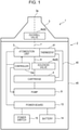
- FIG. 1 schematically illustrates the configuration of the aerosol supply device 1 according to the embodiment.
- Fig. 2 schematically illustrates a liquid 10 being atomized and discharged to the outside of the aerosol supply device 1.
- gaskets or other packing materials are provided between various components of the aerosol supply device 1 from the viewpoint of ensuring hermetic sealing, some of such packing materials are not depicted in Fig. 2 or other figures to facilitate understanding of the present invention.
- the aerosol supply device 1 includes an accommodating part (a cartridge (4)), an atomization unit 5, and a temperature control part (a piezoelectric substrate 5a, an electrode 5c, and an element-heat conduction part 40).
- the accommodating part is configured to accommodate the liquid 10.
- the atomization unit 5 has a storing part 5b to store the liquid 10 supplied from the accommodating part (cartridge 4).
- the atomization unit 5 generates an aerosol 11 by atomizing the liquid 10 stored in the storing part 5b.
- the temperature control part controls the temperature of the liquid 10 at a given location between the accommodating part (cartridge 4) and the storing part 5b.
- the atomization unit 5 includes a vibrating element (piezoelectric substrate 5a) configured to vibrate the liquid 10 to create the aerosol 11, and a vibration source (electrode 5c) configured to, in response to receiving supply of electric power, vibrate the vibrating element.
- a vibrating element piezoelectric substrate 5a
- a vibration source electrode 5c
- the storing part 5b provided to the piezoelectric substrate 5a is a closed-end groove having an elliptical shape in plan view that is formed on the top surface of the piezoelectric substrate 5a.
- the storing part 5b is disposed in at least two places, with the electrode 5c being disposed between the two places.
- the storing part 5b has a through-hole 5d provided in the central portion such that the through-hole 5d extends through the thickness of the piezoelectric substrate 5a.
- the storing part 5b receives the liquid 10 that is supplied from the cartridge 4 via a first passage 6 (tube 6a) and the through-hole 5d by means of a pump 9 described later.
- the electrode 5c is a comb-shaped electrode (also referred to as interdigital transducer (IDT)).
- IDT interdigital transducer
- High-frequency electric power input from a power board 13 to the electrode 5c via a control board 12 is converted into a surface acoustic wave (also referred to as SAW) due to the piezoelectricity of the piezoelectric substrate 5a, and propagates along the surface of the piezoelectric substrate 5a on both sides in the direction of arrangement of the comb teeth.
- SAW surface acoustic wave
- sensors such as a resonant-frequency monitoring sensor for monitoring resonant frequency, or a temperature sensor (not illustrated) capable of detecting the temperature of the liquid 10 immediately before atomization may be provided.
- the thermostat 41 has the function of, when a temperature greater than or equal to a predetermined temperature is reached, delivering heat generated in the piezoelectric substrate 5a to the cartridge 4.
- the thermostat 41 used is one that utilizes changes in the shape of a bimetal element or changes in the volume of a wax. Under normal usage condition such as at the beginning of its use, the thermostat 41 physically disconnects the piezoelectric substrate 5a and the element-heat conduction part 40.
- the housing 45 includes a heat insulation structure (vacuum area 45a), which is provided between the accommodating part (cartridge 4) and the outside of the aerosol supply device 1 and has a lower thermal conductivity than the cartridge 4. More specifically, the heat insulation structure includes the vacuum area 45a, which is a vacuumed space defined between the inner and outer layers of the housing 45.
- the volatilization preventing part 8 (duckbill valve 8b) is capable of transition between a state in which the volatilization preventing part 8 closes the passage (second passage 7) for the aerosol 11, and a state in which the volatilization preventing part 8 opens the passage (second passage 7) for the aerosol 11.
- the Peltier element 48 is operable only by electric wiring.
- the Peltier element 48 is thus easy to handle, is free from risks such as refrigerant gas leaks or corrosive liquid leaks, and allows for easy maintenance.
- the expression “positioned to provide cooling or heating” specifically means that the cooling part (Peltier element 48) or the heating part (Peltier element 48) is positioned to face the piezoelectric substrate 5a while being spaced from or in contact with the piezoelectric substrate 5a.
- the expression “positioned to provide cooling or heating” according to the embodiment means that the Peltier element 48 is positioned such that its upper surface is in contact with the lower surface of the piezoelectric substrate 5a.
- the present invention is not limited to the configuration in which the Peltier element 48 according to the first modification is disposed directly under the piezoelectric substrate 5a.
- the Peltier element 48 may not necessarily be configured to release heat generated from the piezoelectric substrate 5a to the internal space of the housing 45.
- the controller 12a is configured to receive a signal detected from the temperature sensor 49, and control the pump 9 such that when a temperature of the liquid 10 detected by the temperature sensor 49 is greater than or equal to a predetermined temperature or less than or equal to a predetermined temperature, the liquid 10 is pulled back toward the accommodating part from the liquid 10, or the liquid 10 is pushed out toward the atomization unit 5 from the accommodating part.
- the controller 12a controls the pump 9 to allow the liquid 10 to be kept at an appropriate position for atomization.
- the controller 12a is configured to control the electric power to be supplied to a vibration source (such as the electrode 5c or a vibrating motor) such that: when the liquid 10 is at a first temperature, a first electric power is supplied to the vibration source; when the liquid 10 is at a second temperature lower than the first temperature, a second electric power greater than the first electric power is supplied to the vibration source; and when the liquid 10 is at a third temperature higher than the first temperature, a third electric power less than the first electric power is supplied to the vibration source.
- a vibration source such as the electrode 5c or a vibrating motor
- the temperature of the liquid under a low temperature condition (e.g., the second temperature mentioned above) when the rate of atomization is low is used as a reference temperature, and based on the reference temperature, the amount of electric power to be supplied to the electrode 5c is set so as to provide a sufficient rate of atomization of the liquid 10 in a stable manner.
- a temperature control part (external-heat conduction part 50) and a heat insulation structure (urethane foam 55c) according to a second modification are described below with reference to mainly Fig. 5.
- Fig. 5 schematically illustrates a housing 55 with the urethane foam 55c attached thereto, and the external-heat conduction part 50, in accordance with the second modification.
- the exposed part 50a is disposed in a depression 55a provided in the outer surface of the housing 55.
- the depression 55a is provided in at least a portion of the outer surface of the housing 55 (at the same position as the cartridge 4 in the axial direction in accordance with the embodiment).
- heat is supplied from the outside to the accommodating part (cartridge 4) or dissipated from the accommodating part (cartridge 4) to the outside through the outer surface of the housing 55. This makes it possible to control the temperature of the liquid 10 within the accommodating part (cartridge 4).
- the foregoing description of the embodiment is directed to an exemplary configuration in which the liquid 10 is supplied toward the piezoelectric substrate 5a from below, this is not meant to be limiting.
- the liquid 10 may be configured to drip onto the piezoelectric substrate 5a from above.
- the housing 45 and the lid 56 are separate components constituting the device body 2, this is not meant to be limiting of the present invention.
- the housing 45 and the lid 56 may be formed integrally.
Landscapes
- Health & Medical Sciences (AREA)
- Engineering & Computer Science (AREA)
- Life Sciences & Earth Sciences (AREA)
- Animal Behavior & Ethology (AREA)
- Anesthesiology (AREA)
- Biomedical Technology (AREA)
- Heart & Thoracic Surgery (AREA)
- Hematology (AREA)
- Bioinformatics & Cheminformatics (AREA)
- Veterinary Medicine (AREA)
- General Health & Medical Sciences (AREA)
- Public Health (AREA)
- Pulmonology (AREA)
- Pharmacology & Pharmacy (AREA)
- Special Spraying Apparatus (AREA)
- Disinfection, Sterilisation Or Deodorisation Of Air (AREA)
- Electrostatic Spraying Apparatus (AREA)
- Nozzles (AREA)
Abstract
Description
- The present invention relates to an aerosol supply device configured to supply an aerosol of an atomized liquid.
- Aerosol supply devices such as flavor inhalers capable of delivering flavor without combustion of a flavor source such as tobacco are now in widespread use.
- Other known examples of aerosol supply devices include inhalers capable of atomizing a liquid by using ultrasonic waves for supply to the user.
-
PTL 1 discloses an aerosol supply device (referred to as "liquid atomizing apparatus" in PTL 1) configured to generate an aerosol by use of a surface acoustic wave (also referred to as SAW). - More specifically, the aerosol supply device described in
PTL 1 atomizes a liquid supplied from each liquid feeder via a supply port, by using a surface acoustic wave generated by a piezoelectric substrate and comb-shaped electrodes formed on the piezoelectric substrate. - PTL 1:
Japanese Patent Application Publication No. 2012-024646 - With regard to atomization of a liquid, the viscosity/surface tension of a liquid varies with the temperature of the liquid, which leads to fluctuations in the rate of atomization. More specifically, changes in the viscosity/surface tension of a liquid cause changes in the degree of waviness of the liquid surface and the manner in which the liquid particles separate. For this reason, the rate of atomization may fluctuate even for the same electric power supplied to the comb-shaped electrodes and for the same surface acoustic wave energy propagated to the liquid. In other words, for the same electric power supplied to the comb-shaped electrodes, the rate at which a liquid is atomized decreases with increasing viscosity of the liquid or with decreasing surface tension of the liquid.
- In this regard, the aerosol supply device described in
PTL 1 includes no temperature control mechanism. This makes the aerosol supply device susceptible to the influence of ambient temperature, which may result in decreased rate of atomization. - Further, if a liquid freezes under low outside air temperature conditions, this may, in some cases, make it impossible to generate an aerosol due to the inability to supply the liquid onto the piezoelectric substrate.
- The present invention has been made in view of the above-mentioned problems. Accordingly, it is an object of the present invention to provide an aerosol supply device capable of stabilizing the rate of liquid atomization to allow for stable aerosol supply.
- An aerosol supply device according to the present invention includes: an accommodating part configured to accommodate a liquid; an atomization unit having a storing part to store the liquid supplied from the accommodating part, the atomization unit being configured to generate an aerosol by atomizing the liquid stored in the storing part; and a temperature control part configured to control a temperature of the liquid at a given location between the accommodating part and the storing part.
- The aerosol supply device according to the present invention allows for stable supply of a liquid to the atomization unit to provide stable supply of an aerosol to the outside of the aerosol supply device.
-
- [
Fig. 1] Fig. 1 schematically illustrates the configuration of an aerosol supply device according to the embodiment presented herein. - [
Fig. 2] Fig. 2 schematically illustrates a liquid being atomized and discharged to the outside of the aerosol supply device. - [
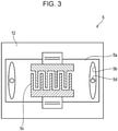
Fig. 3] Fig. 3 is a plan view of an atomization unit. - [
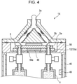
Fig. 4] Fig. 4 schematically illustrates an aerosol supply device including a Peltier element and a temperature sensor, in accordance with a first modification. - [
Fig. 5] Fig. 5 schematically illustrates a housing with a urethane foam attached thereto, and an external-heat conduction part, in accordance with a second modification. - Embodiments of the present invention are described below with reference to the drawings. The following description of the embodiments is illustrative only for purposes of better understanding the present invention, and not to be taken as limiting the present invention. It is to be readily appreciated, therefore, that the shapes, arrangements, materials, or other details of components or parts described below may be changed or modified without departing from the scope of the present invention, and that all such equivalents fall within the scope of the present invention.
- Throughout the drawings, like components are designated by like reference signs, and overlapping descriptions are omitted as appropriate.
- An overview of an
aerosol supply device 1 according to the embodiment is first described below with reference toFigs. 1 and2 .Fig. 1 schematically illustrates the configuration of theaerosol supply device 1 according to the embodiment.Fig. 2 schematically illustrates aliquid 10 being atomized and discharged to the outside of theaerosol supply device 1. Although gaskets or other packing materials are provided between various components of theaerosol supply device 1 from the viewpoint of ensuring hermetic sealing, some of such packing materials are not depicted inFig. 2 or other figures to facilitate understanding of the present invention. - The
aerosol supply device 1 according to the embodiment includes an accommodating part (a cartridge (4)), anatomization unit 5, and a temperature control part (apiezoelectric substrate 5a, anelectrode 5c, and an element-heat conduction part 40). The accommodating part is configured to accommodate theliquid 10. Theatomization unit 5 has a storingpart 5b to store theliquid 10 supplied from the accommodating part (cartridge 4). Theatomization unit 5 generates anaerosol 11 by atomizing theliquid 10 stored in thestoring part 5b. The temperature control part controls the temperature of theliquid 10 at a given location between the accommodating part (cartridge 4) and thestoring part 5b. - In particular, disposing the temperature control part in the form of a heat conduction part, a heat source, or a cooling part directly at "a given location between the accommodating part and the
storing part 5b" is preferred because this allows the temperature of theliquid 10 to be efficiently controlled through supply or absorption of heat. - According to the above-mentioned configuration, by controlling the temperature of the
liquid 10 as theliquid 10 travels from the accommodating part to the storingpart 5b, the rate of atomization of theliquid 10 can be stabilized irrespective of outside air temperature, which allows for stable supply of theaerosol 11 to the outside of theaerosol supply device 1. - The configuration of various parts of the
aerosol supply device 1 is now described below with reference toFig. 3 in addition toFigs. 1 and2 .Fig. 3 is a plan view of theatomization unit 5. - The
aerosol supply device 1 according to a first embodiment supplies theaerosol 11 by atomizing theliquid 10 by vibration (surface acoustic wave). As for the "vibration" mentioned above, using a surface acoustic wave is preferred from the viewpoint of atomization because of the ability to propagate vibration at a high frequency. However, this is not meant to be limiting. Alternatively, the vibration used may be such that the entire object to be vibrated (vibrating element) vibrates. - As illustrated in
Figs. 2 and3 , theatomization unit 5 includes a vibrating element (piezoelectric substrate 5a) configured to vibrate theliquid 10 to create theaerosol 11, and a vibration source (electrode 5c) configured to, in response to receiving supply of electric power, vibrate the vibrating element. - In particular, according to this embodiment, the "vibrating element" is the
piezoelectric substrate 5a having a piezoelectric element, and the "vibration source" is theelectrode 5c having a comb shape. Theelectrode 5c generates a surface acoustic wave on thepiezoelectric substrate 5a. - The above-mentioned configuration allows for efficient utilization of the energy required for atomization based on the surface acoustic wave.
- The
piezoelectric substrate 5a according to this embodiment is made of lithium niobate including a piezoelectric element. Thepiezoelectric substrate 5a has thestoring part 5b to store theliquid 10. - As illustrated in
Fig. 3 , thestoring part 5b provided to thepiezoelectric substrate 5a according to this embodiment is a closed-end groove having an elliptical shape in plan view that is formed on the top surface of thepiezoelectric substrate 5a. The storingpart 5b is disposed in at least two places, with theelectrode 5c being disposed between the two places. The storingpart 5b has a through-hole 5d provided in the central portion such that the through-hole 5d extends through the thickness of thepiezoelectric substrate 5a. The storingpart 5b receives theliquid 10 that is supplied from thecartridge 4 via a first passage 6 (tube 6a) and the through-hole 5d by means of apump 9 described later. - The
electrode 5c is disposed in contact with thepiezoelectric substrate 5a to supply a surface acoustic wave to the liquid 10 stored in the storingpart 5b disposed on thepiezoelectric substrate 5a. - The
electrode 5c is a comb-shaped electrode (also referred to as interdigital transducer (IDT)). High-frequency electric power input from apower board 13 to theelectrode 5c via acontrol board 12 is converted into a surface acoustic wave (also referred to as SAW) due to the piezoelectricity of thepiezoelectric substrate 5a, and propagates along the surface of thepiezoelectric substrate 5a on both sides in the direction of arrangement of the comb teeth. - The number of comb teeth of the
electrode 5c is not limited to the number depicted but is determined based on the efficiency of atomization by which theaerosol 11 is produced by using a surface acoustic wave. The width and spacing of the comb teeth are determined based on a frequency based on the particle size of theaerosol 11 to be produced by atomization. - An important consideration with regard to a surface acoustic wave is the control of the frequency of electric power. Accordingly, sensors such as a resonant-frequency monitoring sensor for monitoring resonant frequency, or a temperature sensor (not illustrated) capable of detecting the temperature of the liquid 10 immediately before atomization may be provided.
- The exterior construction of the
aerosol supply device 1 according to this embodiment mainly includes adevice body 2, and amouthpiece 3 attached to an upper portion of thedevice body 2 and through which theaerosol 11 is to be discharged. - The
aerosol supply device 1 further includes the element-heat conduction part 40. The element-heat conduction part 40 has thermal conductivity, and is connected to the vibrating element (piezoelectric substrate 5a) and to the accommodating part (cartridge 4). As used herein, the expression "having thermal conductivity" means being highly thermally conductive. Accordingly, the element-heat conduction part 40 is made of a material such as copper, aluminum, or carbon. More specifically, the element-heat conduction part 40 has a higher thermal conductivity than another component (which is, for example, thetube 6a in this embodiment) that is in contact with the liquid 10 between thepiezoelectric substrate 5a and thecartridge 4. - The "temperature control part" according to the present invention includes the vibrating element (
piezoelectric substrate 5a), the vibration source (electrode 5c), and the element-heat conduction part 40. - The above-mentioned configuration makes it possible to dissipate, by means of the element-
heat conduction part 40, the heat of thepiezoelectric substrate 5a that is generated in association with the vibration generated from theelectrode 5c and propagated to the vibrating element (piezoelectric substrate 5a) to atomize the liquid 10. This helps to reduce breakage of the vibrating element (piezoelectric substrate 5a) caused by application of heat. Further, the accommodating part (cartridge 4) can be heated. This helps to ensure that even under low temperature environment, the liquid 10 does not freeze within thecartridge 4, which allows for stable aerosol supply by theaerosol supply device 1. - The
aerosol supply device 1 according to this embodiment includes athermostat 41. Thethermostat 41 is capable of physically connecting and disconnecting thepiezoelectric substrate 5a and the element-heat conduction part 40 in accordance with the internal temperature of theaerosol supply device 1. - The
thermostat 41 has the function of, when a temperature greater than or equal to a predetermined temperature is reached, delivering heat generated in thepiezoelectric substrate 5a to thecartridge 4. For example, thethermostat 41 used is one that utilizes changes in the shape of a bimetal element or changes in the volume of a wax. Under normal usage condition such as at the beginning of its use, thethermostat 41 physically disconnects thepiezoelectric substrate 5a and the element-heat conduction part 40. - To atomize the liquid 10, an alternating-current voltage is applied from the
electrode 5c to thepiezoelectric substrate 5a. This results in a SAW being generated on thepiezoelectric substrate 5a, which causes the temperature of thepiezoelectric substrate 5a to rise. Once a temperature greater than or equal to a predetermined temperature is reached, thethermostat 41 automatically operates to physically connect thepiezoelectric substrate 5a and the element-heat conduction part 40. - The above-mentioned configuration is preferred because this allows the temperature of the
piezoelectric substrate 5a to be easily maintained within a predetermined temperature range by means of thecartridge 4. This facilitates stabilization of atomization rate. - In an alternative configuration, the
thermostat 41 may not be used. Instead, acontroller 12a described later may be configured to, in response to a signal associated with a temperature detected by atemperature sensor 49 described later with reference toFig. 4 , drive an actuator (not illustrated) to bring the element-heat conduction part 40 into contact with thepiezoelectric substrate 5a. - In one example, the
controller 12a may be configured to, in response to thetemperature sensor 49 detecting a temperature determined to be the temperature at which the liquid 10 within thecartridge 4 freezes, control the element-heat conduction part 40 into contact with thepiezoelectric substrate 5a. - The above-mentioned configuration is not meant to be limiting. In a still another example, the
piezoelectric substrate 5a and the element-heat conduction part 40 may be configured to be connected at all times. - The
thermostat 41 may not necessarily be designed to dissipate heat from thepiezoelectric substrate 5a through the above-mentioned mechanical action. In one alternative example, thecontroller 12a may utilize the on/off state of an electrical signal provided from thethermostat 41 to switch the directions of current through aPeltier element 48 described later with reference toFig. 4 , to thereby make thePeltier element 48 function as a cooler or function as a heater. - The
mouthpiece 3 according to this embodiment is formed such that, in front view, themouthpiece 3 extends to be wider in an end portion near the bottom, and has a tapered part with a width that decreases toward adischarge port 3a located at the top end of themouthpiece 3 and through which theaerosol 11 is to be discharged externally. - As illustrated in
Fig. 2 , themouthpiece 3 has a passage (second passage 7) through which to pass theaerosol 11 generated from theatomization unit 5. The passage (second passage 7) includes two separate passages each disposed to allow passage of theaerosol 11 generated from the liquid 10 stored in the storingpart 5b disposed in the at least two places. The twosecond passages 7 are formed symmetrically with respect to an imaginary plane passing through thedischarge port 3a. The twosecond passages 7 join into a single passage immediately before reaching thedischarge port 3a located at the top end of themouthpiece 3. - The separate passages (second passages 7) may be formed to have different lengths. In other words, the two
second passages 7 may not necessarily be formed symmetrically with respect to the imaginary plane passing through thedischarge port 3a but may be formed asymmetrically. For example, if the twosecond passages 7 allow passage ofaerosols 11 containing different components, each passage may be formed with a length or shape appropriate to thecorresponding aerosol 11. - In a particularly preferred example for such separate
second passages 7, thesecond passages 7 include an asymmetric portion. The asymmetric portion is formed, for example, by a curvature of one of the twosecond passages 7 that is different from that of the other one of the twosecond passages 7. - According to the above-mentioned configuration, by bringing the
aerosol 11 into contact with a wall surface defining the asymmetric portion of the twosecond passages 7 with different curvatures, particles contained in the aerosol can be deposited/reduced, and their particle size can be adjusted. This allows the user to smoothly inhale theaerosol 11 without experiencing discomfort in the throat caused by components contained in theaerosol 11. - The term "curvature" as used herein is meant to conceptually include not only sharp bends but also gentle bends. Examples of two
second passages 7 with different curvatures include not only two passages that are both bent but also two passages including one straight passage. - The
mouthpiece 3 according to this embodiment includes aduckbill valve 8b, and thesecond passage 7 that splits into two passages. However, themouthpiece 3 may not necessarily be configured as described above. - In one alternative example, the
mouthpiece 3 may not include theduckbill valve 8b, and may be configured such that a singlesecond passage 7 is disposed in contiguity with a single passage (first passage 6) through which the liquid 10 is supplied from thecartridge 4. - The above-mentioned configuration makes it possible to shorten the
second passage 7 through which theaerosol 11 generated from theatomization unit 5 travels before reaching thedischarge port 3a. Shortening thesecond passage 7 in this way helps to reduce condensation of theaerosol 11. - As illustrated in
Fig. 2 , thedevice body 2 includes ahousing 45, and alid 46. Thehousing 45 accommodates components including: thecartridge 4; asolenoid valve 8a; thepump 9; thecontrol board 12 including thecontroller 12a; thepower board 13; and abattery 14. Thelid 46 is attached to the top open end portion of thehousing 45, and has a recess in its upper end portion to accommodate theatomization unit 5. Thedevice body 2 is provided with apower switch 15 exposed to the outside of thedevice body 2. - The
device body 2 has a passage (first passage 6) for the liquid 10 that is defined between thecartridge 4, which will be described later, and theatomization unit 5. Further, the passage (second passage 7) for theaerosol 11 is defined between theatomization unit 5 and the outside of thedevice body 2 so as to extend from thedevice body 2 to themouthpiece 3. - The
housing 45 according to this embodiment includes a heat insulation structure (vacuum area 45a), which is provided between the accommodating part (cartridge 4) and the outside of theaerosol supply device 1 and has a lower thermal conductivity than thecartridge 4. More specifically, the heat insulation structure includes thevacuum area 45a, which is a vacuumed space defined between the inner and outer layers of thehousing 45. - The term "vacuum" as used herein refers to "the state of a space filled with gas with a pressure lower than atmospheric pressure", and is meant to permit the presence of trace amounts of molecules. The presence of the
vacuum area 45a results in extremely low thermal conductivity, which contributes to heat insulation. This helps to reduce the influence of outside air temperature on the liquid 10 within thecartridge 4. - The
cartridge 4 according to this embodiment includes a body part 4a, abase plate 4b, and a slidingblock 4d. Thebase plate 4b is integrated with the bottom portion of the body part 4a. The slidingblock 4d is disposed inside thecartridge 4, and arranged in a watertight manner on the inner wall surface of the body part 4a. The slidingblock 4d is capable of sliding within the body part 4a. - The
base plate 4b has a through-hole 4c extending through the thickness of thebase plate 4b. Apush rod 9b of thepump 9, which will be described later, can be inserted into the through-hole 4c. - According to the this embodiment, the liquid 10 can be supplied separately from each of two
cartridges 4 to the corresponding one of two storingparts 5b provided to thepiezoelectric substrate 5a of theatomization unit 5. - However, the present invention is not limited to this configuration. Alternatively, the liquid 10 may be supplied from a
single cartridge 4 to two storingparts 5b. This configuration makes it possible to reduce the number ofsolenoid valves 8a, which will be described later. That is, thesolenoid valve 8a may be simply provided to a portion of thetube 6a near thecartridge 4, at a position before where thetube 6a splits in two toward the two storingparts 5b. - The above-mentioned configuration makes it possible to, by means of a
single solenoid valve 8a, control whether to supply the liquid 10 to two storingparts 5b or stop the supply of the liquid 10. - The
aerosol supply device 1 may further include a plurality ofcartridges 4. If two ormore cartridges 4 are to be used,individual cartridges 4 may accommodateliquids 10 with different components such as taste or fragrance. - The accommodating part according to the present invention may not necessarily be the
cartridge 4 that is removable, but may be a container pre-installed on the device body 2 (i.e., a refillable container). If such a pre-installed container is to be used, the container may be filled with the liquid 10 in a similar manner. That is, another passage communicating with the container and the outside may be formed in advance, and the liquid 10 may be charged into the container through the other passage to fill the container with the liquid 10. - The above-mentioned configuration eliminates the need for the user to, when refilling the container with the liquid 10, remove pre-installed components including the
solenoid valve 8a, thecartridge 4, and thetube 6a connecting thesolenoid valve 8a and thecartridge 4, and attach these components again. - The liquid 10 may include a solvent such as water, glycerol, propylene glycol, or ethanol. Further, the liquid 10 may include a solute containing a component such as taste or fragrance. Exemplary solvents include volatile components such as tobacco extracts, menthol, linalool, limonene, or vanillin, or non-volatile components, for example, sugars such as fructose, glucose, sucrose, or lactose, acids such as malic acids or citric acids, or salts.
- The liquid 10 may be emulsified by an emulsifier, or may be suspended by a dispersant. An antifreeze component such as the glycerol, propylene glycol, or ethanol mentioned above may be added to the liquid 10 to produce an antifreeze solution with a melting point of less than or equal to -20 degrees, more preferably less than or equal to -30 degrees. The presence of such an antifreeze component in the liquid 10 helps to prevent the liquid 10 within the
atomization unit 5 from freezing even when the outside environment is at low temperature, such as in winter. - The
solenoid valve 8a, which is disposed between thetubes 6a, is connected to thetubes 6a that connect thecartridge 4 and theatomization unit 5 within thedevice body 2. - The
solenoid valve 8a includes an open/close part (not illustrated) capable of opening and closing thefirst passage 6 through which the liquid 10 flows. - According to the configuration mentioned above, by the
controller 12a operating the open/close part of thesolenoid valve 8a to close thefirst passage 6, volatilization of the liquid 10 from the accommodating part (cartridge 4) can be prevented. Further, by thecontroller 12a operating the open/close part of thesolenoid valve 8a to open thefirst passage 6, the liquid 10 can be supplied to theatomization unit 5, and consequently theaerosol 11 can be supplied to the user. - In the following description of this embodiment, the
duckbill valve 8b constituting a check valve is described as an example of avolatilization preventing part 8 configured to open and close the passage for theaerosol 11. Theduckbill valve 8b according to this embodiment is a valve including opposed flat plates made of a soft resin material, with the spacing between the flat plates decreasing progressively toward the downstream (suction) side. Theduckbill valve 8b is configured such that in normal condition, the flat plates contact each other to close the passage, and when a suction pressure is applied from the downstream side, the flat plates move away from each other to open the passage. - The
duckbill valve 8b acts as a small check valve to allow the passage for theaerosol 1 1 to narrow. This makes it possible to reduce the size of themouthpiece 3 and therefore the size of theaerosol supply device 1. Theduckbill valve 8b is preferred for its ability to open by a small suction force without being affected by the direction of gravity, and for its ability to naturally close the open/close part due to the elastic restoring force once the suction stops. - The two
second passages 7 of themouthpiece 3 are each provided with the volatilization preventing part 8 (duckbill valve 8b). - The volatilization preventing part (
duckbill valve 8b) is disposed in each of the two passages at an equal distance from thedischarge port 3a. - According to the above-mentioned configuration, the
aerosol 11 generated from the storingpart 5b disposed in two places can be discharged through thedischarge port 3a at the same timing. This helps to reduce variations in the rate at which theaerosol 11 is discharged. - The volatilization preventing part 8 (
duckbill valve 8b) is capable of transition between a state in which thevolatilization preventing part 8 closes the passage (second passage 7) for theaerosol 11, and a state in which thevolatilization preventing part 8 opens the passage (second passage 7) for theaerosol 11. - According to the above-mentioned configuration, closing the
second passage 7 for theaerosol 11 by means of theduckbill valve 8b makes it possible to limit volatilization of the liquid 10 within a hermetically sealed space with the saturated vapor pressure of the liquid 10 as an upper limit to thereby inhibit precipitation of the solute on theatomization unit 5. This helps to reduce deterioration of atomization efficiency. - The
volatilization preventing part 8 according to this embodiment is a valve element (duckbill valve 8b) configured to close the passage (second passage 7) for theaerosol 11 in a first state, and open the passage (second passage 7) for theaerosol 11 in a second state in which the pressure condition has changed due to suction applied by the user. The volatilization preventing part (duckbill valve 8b) is disposed between the storingpart 5b and thedischarge port 3a. - More specifically, the "first state" according to this embodiment refers to a state in which the air inside the
aerosol supply device 1 is not being sucked by the user through thedischarge port 3a. Conversely, the "second state" refers to a state in which the air inside theaerosol supply device 1 is being sucked by the user through thedischarge port 3a. - According to the above-mentioned configuration, the open/close part is a valve element. Consequently, while suction is applied by the user, the
aerosol 11 can be supplied to the user, and while suction is not applied by the user, thesecond passage 7 is closed to prevent volatilization of the liquid 10 to the external environment through thedischarge port 3a. - Further, as described above, the
aerosol supply device 1 that atomizes the liquid 10 by means of a surface acoustic wave includes the volatilization preventing part (duckbill valve 8b) disposed between the storingpart 5b and thedischarge port 3a. As a result, precipitation of the solute on the storingpart 5b can be prevented. This helps to reduce variations in the concentration of the solute in the liquid 10, thus allowing stable taste or fragrance. - The "valve element" according to the present invention is not limited to the
duckbill valve 8b. The valve element may be a solenoid valve similar to thesolenoid valve 8a, an air-operated pinch valve with a tube closed by the pressure applied by supplied air, or an electrically driven valve. For example, if the electrically driven valve is to be used, a portion of thesecond passage 7 may be simply formed by a flexible tube to which the electrically driven valve can be connected. - By using an electrically driven valve instead of the
duckbill valve 8b, theaerosol 11 can be discharged externally by thecontroller 12a controlling the opening action of the electrically driven valve, without the user having to suck on thedischarge port 3a of themouthpiece 3 and apply suction pressure. That is, an electrically driven valve is suited for use in diffusers that do not rely on the suction applied by the user to spray an aerosol. For example, the opening action of an electrically driven valve is controlled by thecontroller 12a in accordance with an operation performed on thepower switch 15 as will be described later. - Although the
duckbill valve 8b as a check valve has been described above as an exemplary "valve element", this is not meant to be limiting. The valve element may be any valve element capable of preventing volatilization due to its ability to close a passage in its normal state. For example, the valve element may be one capable of permitting backflow when positive pressure is being applied. - Likewise, the volatilization preventing part for opening and closing the
first passage 6 is not limited to thesolenoid valve 8a but may be an air-operated pinch valve with a tube closed by the pressure applied by supplied air, or an electrically driven valve. - In another example, the volatilization preventing part for opening and closing the
first passage 6 or thesecond passage 7 may be one that is driven non-electrically. That is, the volatilization preventing part used may be one that causes thefirst passage 6 or thesecond passage 7 to be opened and closed by a physical drive action (movement of a barrier) (not illustrated) responsive to the user attaching themouthpiece 3 to thedevice body 2 or pushing themouthpiece 3 into thedevice body 2. - With no suction pressure applied, the
duckbill valve 8b closes thesecond passage 7. This helps to prevent foreign matter from passing into theatomization unit 5 even if the foreign matter enters theaerosol supply device 1 through thedischarge port 3a when theaerosol supply device 1 is not in use. Discharge of theaerosol 11 containing such foreign mater can be thus reduced, which proves advantageous also from the viewpoint of sanitation. - The
aerosol supply device 1 further includes thepump 9 capable of supplying the liquid 10 to theatomization unit 5. Thepump 9 according to this embodiment is a syringe pump capable of supplying the liquid 10 to theatomization unit 5 from thecartridge 4, and also pulling the liquid 10 back toward the accommodating part (cartridge 4) from theatomization unit 5. - Although described in more detail later, using a syringe pump as the
pump 9 makes it possible to pull the liquid 10 back toward the accommodating part (cartridge 4) from theatomization unit 5. - By thus reducing the amount of the liquid 10 remaining on the
atomization unit 5, precipitation of the solute on theatomization unit 5 can be reduced. - More specifically, the
pump 9 includes amotor 9a, and thepush rod 9b capable of advancing or retracting as themotor 9a rotates. As thepump 9 operates, thepush rod 9b passes through the through-hole 4c and pushes in the slidingblock 4d upward. At this time, the liquid 10 is pushed in by the slidingblock 4d and supplied to theatomization unit 5. - If the
pump 9 is a syringe pump as described above, by retracting thepush rod 9b from the through-hole 4c of thecartridge 4, the liquid 10 can be pulled in the reverse direction. The liquid 10 can be thus pulled in to a position where the liquid 10 leaves the storingpart 5b. This configuration is preferred for the ability to reduce precipitation of the solute on the storingpart 5b. - For instance, there are cases where, if the liquid 10 contains citric acid mixed therein, the citric acid that has not turned into mist may precipitate out of the liquid 10 remaining in the storing
part 5b and solidify. In this regard, by pulling the liquid 10 in the reverse direction from the storingpart 5b by means of thepump 9 as described above, precipitation of citric acid on the storingpart 5b is reduced to thereby reduce variations in the concentration of citric acid in the liquid 10. This allows stable taste or fragrance. - Further, the sliding
block 4d that comes into contact with the liquid 10 is disposed in thecartridge 4. This means that the pump 9 (pushrod 9b) does not directly contact the liquid 10. As a result, for instance, in changing different kinds ofcartridges 4 to change the kind of the liquid 10 having taste or fragrance, even if thepump 9 is not replaced, mixing of components such as taste or fragrance do not occur before and after the changing of thecartridges 4. - However, the pump according to the present invention may not necessarily be configured as described above but may be, for example, a piezoelectric pump (not illustrated). Using a piezoelectric pump makes it possible to provide a product with low electric power consumption. In another example, the liquid 10 may be supplied by capillary action.
- The
aerosol supply device 1 further includes thecontrol board 12 having thecontroller 12a configured to control the electric power to be supplied to the vibration source (electrode 5c). - The
controller 12a controls various electronics. In particular, thecontroller 12a controls theatomization unit 5 such that electric power is supplied to theelectrode 5c to generate a surface acoustic wave on the surface of thepiezoelectric substrate 5a. - The
controller 12a also controls operations of components such as thepump 9 and thesolenoid valve 8a. Thecontroller 12a according to this embodiment changes thesolenoid valve 8a from a closed state, which is a normal state, to an open state in response to receiving a signal transmitted from thepower board 13 and indicating that theaerosol supply device 1 has been activated by the user operating thepower switch 15. - Further, the
controller 12a activates themotor 9a of thepump 9 to cause thepush rod 9b to push in the slidingblock 4d in a direction (upward) that diminishes the volume of thecartridge 4. Consequently, the liquid 10 is supplied to the storingpart 5b through thefirst passage 6. The liquid 10 is thus resonated and atomized by a surface acoustic wave on the surface of thepiezoelectric substrate 5a. - In this state, as the user sucks in the air inside the
aerosol supply device 1 through thedischarge port 3a, the pressure in a portion of theduckbill valve 8b near thedischarge port 3a becomes negative. This causes theduckbill valve 8b to open, which allows the user to suck in theaerosol 11 passing through theduckbill valve 8b. - The
controller 12a is configured to, when theaerosol supply device 1 becomes no longer used, for example, when thepower switch 15 is switched off, operate thesolenoid valve 8a (open/close part) to close the passage for the liquid 10. - In a particularly preferred example, the
controller 12a is configured to, in closing the passage for the liquid 10 as described above, control thepump 9 such that the liquid 10 is supplied to theatomization unit 5 before the liquid 10 is pulled back toward the accommodating part (cartridge 4) from theatomization unit 5, and cause the open/close part (solenoid valve 8a) to close the passage for the liquid 10 supplied to theatomization unit 5. - According to the above-mentioned configuration, if the solute precipitates out on the
atomization unit 5, the liquid 10 is supplied to thecartridge 4 to dissolve the solute again. Then, the liquid is pulled back toward thecartridge 4 from theatomization unit 5. This allows the amount of solute remaining on theatomization unit 5 to be reduced in comparison to a case where the liquid 10 is pulled back toward thecartridge 4 without being first supplied to theatomization unit 5. This helps to further reduce precipitation of the solute on the atomization unit 5 (piezoelectric substrate 5a). - In another alternative example, the
controller 12a may be configured to, based on the amount of consumption of the liquid 10 per unit time as detected by a sensor (not illustrated), control the output of thepump 9 to change the speed at which to feed thepush rod 9b, or control SAW output to stabilize the rate of atomization. - A temperature control part (Peltier element 48) according to a first modification is now described below with reference to mainly
Fig. 4. Fig. 4 schematically illustrates an aerosol supply device IX including thePeltier element 48 and thetemperature sensor 49, in accordance with a first modification. - The temperature control part according to the first modification includes a cooling part (Peltier element 48) configured to absorb heat at a given location between the accommodating part (cartridge 4) and the storing
part 5b. - In another example, the temperature control part may include a heating part (Peltier element 48) configured to release heat at a given location between the accommodating part (cartridge 4) and the storing
part 5b. - According to the above-mentioned configuration, the temperature control part includes a cooling part (Peltier element 48) or a heating part (Peltier element 48) configured to cool or heat a given location between the accommodating part (cartridge 4) and the storing
part 5b to control the temperature of the liquid 10 passing through the location to thereby stabilize the rate of atomization. In other words, the above-mentioned configuration helps to reduce the influence of outside air temperature. - In particular, using the
Peltier element 48 as the cooling part is preferred in comparison to using an air-cooling device because at least a portion of the interior of the aerosol supply device IX can be suitably cooled to a temperature less than or equal to the outside air temperature. - For example, the
Peltier element 48 does not use a refrigerant such as chlorofluorocarbon and thus has very little impact on the environment. Further, thePeltier element 48 allows for compact/lightweight construction and flexible shape design, and makes it easily possible to avoid interference with other components within the device. - Further, the
Peltier element 48 has superior temperature response, and is capable of both cooling and heating. Accordingly, thePeltier element 48 enables temperature control near room temperature, and the absence of any movable part eliminates any potential vibration/noise. Due to the absence of any mechanical component that is subject to fatigue/breakage, thePeltier element 48 allows for maximum lifetime and reliability as cooling means. - Further, the
Peltier element 48 is operable only by electric wiring. ThePeltier element 48 is thus easy to handle, is free from risks such as refrigerant gas leaks or corrosive liquid leaks, and allows for easy maintenance. - However, the cooling part according to the present invention may not necessarily be configured as described above. Alternatively, the cooling part may be formed by an air-cooling device such as a fan, a water-cooling device, or other devices (not illustrated).
- In one example, the cooling part may include a passage through which water can be supplied from the outside to a target part to be cooled (e.g., the
piezoelectric substrate 5a). In this case, air may be blown against the target part by a fan (not illustrated) to promote evaporation of water, and the resulting heat of vaporization may be used to cool the target part. In another example, a refrigerant such as chlorofluorocarbon or hydrofluorocarbon may be fed into the device, and the refrigerant may be rapidly expanded by an expansion valve (not illustrated) disposed within the device to thereby cool air that contacts the target part. The refrigerant may be made to circulate inside and outside the device as in the case of a heat pump. - In particular, the cooling part (Peltier element 48) or heating part (Peltier element 48) according to the first modification is positioned to provide cooling or heating to the
piezoelectric substrate 5a. - The expression "positioned to provide cooling or heating" specifically means that the cooling part (Peltier element 48) or the heating part (Peltier element 48) is positioned to face the
piezoelectric substrate 5a while being spaced from or in contact with thepiezoelectric substrate 5a. The expression "positioned to provide cooling or heating" according to the embodiment means that thePeltier element 48 is positioned such that its upper surface is in contact with the lower surface of thepiezoelectric substrate 5a. - The above-mentioned configuration makes it possible to control the temperature of the
piezoelectric substrate 5a with which the liquid 10 comes into contact during atomization of the liquid 10. This allows the rate of atomization to be suitably controlled in comparison to a case where the temperature of a part remote from where atomization takes place is controlled. - In particular, disposing the cooling part (Peltier element 48) at the above-mentioned location allows the cooling part to suitably cool the
piezoelectric substrate 5a, which tends to easily rise in temperature due to a surface acoustic wave generated thereon. This leads to extended lifetime of thepiezoelectric substrate 5a. - More specifically, a
lid 56 has a through-hole 56a provided in a part of thelid 56 facing the central portion of the lower surface of thePeltier element 48. Due to the presence of the through-hole 56a, the lower surface of thePeltier element 48 faces the internal space of thehousing 45. - The above-mentioned configuration allows the
Peltier element 48 to, under control by thecontroller 12a, release heat generated from thepiezoelectric substrate 5a to the internal space of thehousing 45. - The present invention is not limited to the configuration in which the
Peltier element 48 according to the first modification is disposed directly under thepiezoelectric substrate 5a. In other words, thePeltier element 48 may not necessarily be configured to release heat generated from thepiezoelectric substrate 5a to the internal space of thehousing 45. - For example, the
Peltier element 48 may be configured to release heat generated from thepiezoelectric substrate 5a to the outside of the aerosol supply device IX. In other words, thePeltier element 48 may be configured to allow heat exchange in a desired direction between the inside of thehousing 45 and the outside of the aerosol supply device IX. - More specifically, the
Peltier element 48 may be disposed in thehousing 45 such that one side of thePeltier element 48 is exposed to the outside of the aerosol supply device IX, and a side opposite to the one side of thePeltier element 48 is exposed to the internal space of thehousing 45. According to the above-mentioned configuration, whether to provide cooling or heating to the internal space of thehousing 45 can be switched simply by changing the direction of current to be passed through thePeltier element 48. - The temperature control part (heating part) is used to heat the
cartridge 4 to prevent the liquid 10 from freezing within thecartridge 4 under low outside air temperature conditions or to melt thefrozen liquid 10 into liquid form again. The temperature control unit used at this time is not limited to thePeltier element 48. Alternatively, for example, a heater (not illustrated) may not be used. - As described above with reference to
Fig. 2 , theaerosol supply device 1 according to the embodiment mentioned above includes thepump 9 capable of supplying the liquid 10 to theatomization unit 5, and thecontroller 12a configured to control the electric power to be supplied to thepump 9. In addition to these components, the aerosol supply device IX according to the first modification further includes thetemperature sensor 49 illustrated inFig. 4 . Thetemperature sensor 49 detects the temperature around the accommodating part (cartridge 4). Thetemperature sensor 49 includes, for example, a thermocouple or resistance temperature detector. - As with the
pump 9 according to the first embodiment, thepump 9 is a syringe pump capable of pulling the liquid 10 back toward the accommodating part (cartridge 4) from theatomization unit 5. - The
controller 12a is configured to receive a signal detected from thetemperature sensor 49, and control thepump 9 such that when a temperature of the liquid 10 detected by thetemperature sensor 49 is greater than or equal to a predetermined temperature or less than or equal to a predetermined temperature, the liquid 10 is pulled back toward the accommodating part from the liquid 10, or the liquid 10 is pushed out toward theatomization unit 5 from the accommodating part. - In one example, the "predetermined temperature" is a temperature represented by temperature information set in advance prior to product shipment and stored in the
control board 12. In a further preferred example, the predetermined temperature is a variable temperature that can be set after product shipment, as this allows the temperature to be changed in accordance with the external environment, product condition, or other circumstances. - For instance, in summer when the outside air temperature is high, the liquid 10 expands, which may in some cases cause the liquid 10 to spill over from a predetermined area (e.g., the storing
part 5b). Such a situation, that is, a situation where due to the influence of outside air temperature, the liquid 10 spills out from a predetermined area and is no longer atomized, can be prevented or reduced by pulling back the liquid 10 toward the accommodating part by means of thepump 9. - In winter when the outside air temperature is low, the liquid 10 contracts, and thus may not reach the
atomization unit 5 in some cases. Such a situation, that is, a situation where due to the influence of outside air temperature, the liquid 10 does not reach theatomization unit 5 and is longer atomized, can be prevented or reduced by pushing out the liquid 10 toward theatomization unit 5 by means of thepump 9. - In other words, according to the above-mentioned configuration, the
controller 12a controls thepump 9 to allow the liquid 10 to be kept at an appropriate position for atomization. - In another preferred example, the
controller 12a is configured to, upon receiving a signal indicative of thepower switch 15 being turned off, control thepump 9 such that the liquid 10 is pulled back into thecartridge 4 from theatomization unit 5. This helps to prevent leakage of the liquid from the storingpart 5b. - In another preferred example, the
controller 12a is configured to, upon receiving a signal indicative of thepower switch 15 being turned on, control thepump 9 to feed the liquid 10 to an appropriate liquid position (e.g., the storingpart 5b) and keep the liquid 10 on standby so that the liquid 10 is ready to be atomized whenever needed. - The
controller 12a is configured to control the electric power to be supplied to a vibration source (such as theelectrode 5c or a vibrating motor) such that: when the liquid 10 is at a first temperature, a first electric power is supplied to the vibration source; when the liquid 10 is at a second temperature lower than the first temperature, a second electric power greater than the first electric power is supplied to the vibration source; and when the liquid 10 is at a third temperature higher than the first temperature, a third electric power less than the first electric power is supplied to the vibration source. - In this regard, if the liquid 10 is at a high temperature, supplying to the
electrode 5c the same electric power as that when the liquid 10 is at a low temperature results in increased rate of atomization due to low viscosity of the liquid 10 in comparison to when the liquid 10 is at a low temperature. Accordingly, the electric power to be supplied to theelectrode 5c is decreased to thereby reduce variations in the rate of atomization. - Conversely, if the liquid 10 is at a low high temperature, supplying to the
electrode 5c the same electric power as that when the liquid 10 is at a high temperature results in decreased rate of atomization due to high viscosity of the liquid 10 in comparison to when the liquid 10 is at a high temperature. Accordingly, the electric power to be supplied to theelectrode 5c is increased to thereby reduce variations in the rate of atomization. - According to the above-mentioned configuration, by controlling the electric power to be supplied to the vibration source (such as the
electrode 5c or a vibrating motor), the amount ofaerosol 11 generated by atomization can be finely controlled. This helps to stabilize the rate of atomization. - In a particularly preferred example, the temperature of the liquid under a low temperature condition (e.g., the second temperature mentioned above) when the rate of atomization is low is used as a reference temperature, and based on the reference temperature, the amount of electric power to be supplied to the
electrode 5c is set so as to provide a sufficient rate of atomization of the liquid 10 in a stable manner. - The term "temperature of the liquid 10" as used herein refers to a temperature calculated based on a temperature detected by the
temperature sensor 49 disposed near the cartridge 4 (within the space around the cartridge 4). However, this is not meant to be limiting. Alternatively, the above-mentioned temperature may be a temperature directly detected by a temperature sensor (not illustrated) disposed in direct contact with the liquid 10. - Lastly, a temperature control part (external-heat conduction part 50) and a heat insulation structure (
urethane foam 55c) according to a second modification are described below with reference to mainlyFig. 5. Fig. 5 schematically illustrates ahousing 55 with theurethane foam 55c attached thereto, and the external-heat conduction part 50, in accordance with the second modification. - An
aerosol supply device 1Y according to the second modification includes thehousing 55 facing the outside of theaerosol supply device 1Y and covering at least the accommodating part (cartridge 4). The temperature control part includes the external-heat conduction part 50. The external-heat conduction part 50 has thermal conductivity, and is connected to the accommodating part (cartridge 4) and to the outer surface of thehousing 55. As used herein, the expression "having thermal conductivity" means being highly thermally conductive. Accordingly, the external-heat conduction part 50 includes a material such as copper, aluminum, or carbon. More specifically, the external-heat conduction part 50 has a higher thermal conductivity than another component (which is, for example, thehousing 55 in accordance with the embodiment) disposed at a location between the outside and thecartridge 4. - The external-
heat conduction part 50 includes an exposedpart 50a, anintroduction part 50b, and acontact part 50c. The exposedpart 50a is an externally exposed part. Theintroduction part 50b is connected to the exposedpart 50a via a through-hole 55b, which is provided in thehousing 55, to introduce heat inward. Thecontact part 50c is connected to theintroduction part 50b, and contacts thecartridge 4. - The exposed
part 50a is disposed in adepression 55a provided in the outer surface of thehousing 55. Thedepression 55a is provided in at least a portion of the outer surface of the housing 55 (at the same position as thecartridge 4 in the axial direction in accordance with the embodiment). - The exposed
part 50a is disposed closer to the bottom of thedepression 55a than to the outer edge of thedepression 55a. This configuration helps to ensure that another object does not come into contact with the exposedpart 50a unless intended otherwise. This makes it possible to reduce unexpected propagation of heat to the exposedpart 50a from the other object. - According to the above-mentioned configuration, heat is supplied from the outside to the accommodating part (cartridge 4) or dissipated from the accommodating part (cartridge 4) to the outside through the outer surface of the
housing 55. This makes it possible to control the temperature of the liquid 10 within the accommodating part (cartridge 4). - Examples of means for supplying external heat include one utilizing body temperature (human hand) and one utilizing chemical heat generation (portable heat pack).
- The heat conduction part (element-
heat conduction part 40 or external-heat conduction part 50) may be formed with a cylindrical or box-shaped part so as to surround thecartridge 4. - Although the heat insulation structure of the
aerosol supply device 1 according to the first embodiment illustrated inFig. 2 is described above as being formed by thevacuum area 45a, this is not meant to be limiting. For example, theaerosol supply device 1Y according to the second modification includes a heat insulation structure formed by theurethane foam 55c bonded by using an adhesive so as to cover the inner surface of thehousing 55. Using theurethane foam 55c allows a heat insulation structure to be formed easily. Theurethane foam 55c has a through-hole provided in a portion of theurethane foam 55c. Theintroduction part 50b of the external-heat conduction part 50 can be inserted through the through-hole. - Each of the
aerosol supply devices 1, IX, and 1Y according to the embodiment and their modifications mentioned above is described above as being configured to atomize a liquid by using a SAW. However, the aerosol supply device according to the present invention may not necessarily be an aerosol supply device that atomizes a liquid by using a SAW, but may be an aerosol supply device that atomizes a liquid by using, for example, a heating device such as a heater, or an ultrasonic wave oscillator. - Examples of aerosol supply devices other than electronic cigarettes may include inhalers for ejecting a liquid, and diffusers for diffusing fragrance.
- Although the foregoing description of the embodiment is directed to an exemplary configuration in which the liquid 10 is supplied toward the
piezoelectric substrate 5a from below, this is not meant to be limiting. Alternatively, the liquid 10 may be configured to drip onto thepiezoelectric substrate 5a from above. - Although the foregoing description of the embodiment and their modifications mentioned above is directed to a case where the
housing 45 and thelid 56 are separate components constituting thedevice body 2, this is not meant to be limiting of the present invention. Alternatively, thehousing 45 and thelid 56 may be formed integrally. - In another example, individual components of the aerosol supply device according to the present invention may not necessarily exist as independent components. For instance, the following cases may be permitted: plural components are formed as a single part; a single component is formed by plural components; a component constitutes a portion of another component; and a component and another component partially overlap.
- It is to be readily appreciated that the features described above with reference to the embodiment and their modifications mentioned above can be used in combination. For example, the aerosol supply device may include, as a temperature control part, all of the following components: the element-
heat conduction part 40, thePeltier element 48, and the external-heat conduction part 50. - The present application claims priority from
Japanese Patent Application No. 2019-074361 filed on April 9, 2019 - The embodiment described in the foregoing encompass technical ideas described below.
- (1) An aerosol supply device including:
- an accommodating part configured to accommodate a liquid;
- an atomization unit having a storing part to store the liquid supplied from the accommodating part, the atomization unit being configured to generate an aerosol by atomizing the liquid stored in the storing part; and
- a temperature control part configured to control a temperature of the liquid at a given location between the accommodating part and the storing part.
- (2) The aerosol supply device according to (1),
- wherein the aerosol supply device is configured to supply the aerosol by atomizing the liquid by vibration,
- wherein the atomization unit includes
- a vibrating element configured to vibrate the liquid to form the aerosol, and
- a vibration source configured to, in response to receiving supply of electric power, vibrate the vibrating element,
- wherein the aerosol supply device further includes an element-heat conduction part having thermal conductivity, the element-heat conduction unit being connected to the vibrating element and to the accommodating part, and
- wherein the temperature control part includes the vibrating element, the vibration source, and the element-heat conduction part.
- (3) The aerosol supply device according to (1) or (2),
- wherein the aerosol supply device is configured to supply the aerosol by atomizing the liquid by vibration,
- wherein the atomization unit includes
- a vibrating element configured to vibrate the liquid to form the aerosol, and
- a vibration source configured to, in response to receiving supply of electric power, vibrate the vibrating element,
- wherein the aerosol supply device further includes a controller configured to control the electric power to be supplied to the vibration source, and
- wherein the controller is configured to,
- when the liquid is at a first temperature, supply a first electric power as the electric power,
- when the liquid is at a second temperature lower than the first temperature, supply a second electric power greater than the first electric power as the electric power, and
- when the liquid is at a third temperature higher than the first temperature, supply a third electric power less than the first electric power as the electric power.
- (4) The aerosol supply device according to (2) or (3),
- wherein the aerosol supply device is configured to supply the aerosol by atomizing the liquid by a surface acoustic wave,
- wherein the vibrating element is a piezoelectric substrate having a piezoelectric element, and
- wherein the vibration source is a comb-shaped electrode configured to generate a surface acoustic wave on the piezoelectric substrate.
- (5) The aerosol supply device according to any one of (1) to (4), wherein a heat insulation structure is disposed between the accommodating part and an outside of the aerosol supply device, the heat insulation structure having a lower thermal conductivity than the accommodating part.
- (6) The aerosol supply device according to any one of (1) to (5), further including
- a housing facing an outside of the aerosol supply device and covering at least the accommodating part, and
- wherein the temperature control part includes an external-heat conduction part having thermal conductivity, the external-heat conduction part being connected to the accommodating part and to an outer surface of the housing.
- (7) The aerosol supply device according to any one of (1) to (6), wherein the temperature control part includes a cooling part configured to absorb heat, or a heating part configured to release heat, at a given location between the accommodating part and the storing part.
- (8) The aerosol supply device according to any one of (1) to (7), wherein the temperature control part includes a heating part configured to release heat at a given location between the accommodating part and the storing part.
- (9) The aerosol supply device according to (8) as dependent on (7),
- wherein the aerosol supply device is configured to supply the aerosol by atomizing the liquid by a surface acoustic wave,
- wherein the atomization unit includes
- a piezoelectric substrate having a piezoelectric element, the piezoelectric substrate being configured to vibrate the liquid to form the aerosol, and
- a comb-shaped electrode configured to, in response to receiving supply of electric power, generate a surface acoustic wave on the piezoelectric substrate, and
- wherein the cooling part or the heating part is positioned to provide cooling or heating to the piezoelectric substrate.
- (10) The aerosol supply device according to any one of (1) to (9), wherein the temperature control part includes a Peltier element.
- (11) The aerosol supply device according to any one of (1) to (10), further including:
- a pump capable of supplying the liquid to the atomization unit;
- a controller configured to control electric power to be supplied to the pump; and
- a temperature sensor configured to detect a temperature around the accommodating part,
- wherein the pump is a syringe pump capable of pulling back the liquid toward the accommodating part from the atomization unit, and
- wherein the controller is configured to,
when a temperature of the liquid detected by the temperature sensor is greater than or equal to a predetermined temperature or less than or equal to a predetermined temperature, control the pump to pull back the liquid toward the accommodating part from the atomization unit or to push out the liquid toward the atomization unit from the accommodating part.
-
- 1, 1X, 1Y
- aerosol supply device
- 2
- device body
- 3
- mouthpiece
- 3a
- discharge port
- 4
- cartridge (accommodating part)
- 4a
- body part
- 4b
- base plate
- 4c
- through-hole
- 4d
- sliding block
- 5
- atomization unit
- 5a
- piezoelectric substrate (substrate, vibrating element, temperature control part)
- 5b
- storing part
- 5c
- electrode (vibration source, temperature control part)
- 5d
- through-hole
- 6
- first passage
- 6a
- tube
- 7
- second passage
- 8
- volatilization preventing part
- 8a
- solenoid valve
- 8b
- duckbill valve
- 9
- pump
- 9a
- motor
- 9b
- push rod
- 10
- liquid
- 11
- aerosol
- 12
- control board
- 12a
- controller
- 13
- power board
- 14
- battery
- 15
- power switch
- 40
- element-heat conduction part (temperature control part)
- 41
- thermostat (temperature control part)
- 45
- housing
- 45a
- vacuum area (heat insulation structure)
- 46
- lid
- 48
- Peltier element (cooling part, heating part, temperature control part)
- 49
- temperature sensor
- 50
- external-heat conduction part (temperature control part)
- 50a
- exposed part
- 50b
- introduction part
- 50c
- contact part
- 55
- housing
- 55a
- depression
- 55b
- through-hole
- 55c
- urethane foam (heat insulation structure)
- 56
- lid
- 56a
- through-hole
Claims (11)
- An aerosol supply device comprising:an accommodating part configured to accommodate a liquid;an atomization unit having a storing part to store the liquid supplied from the accommodating part, the atomization unit being configured to generate an aerosol by atomizing the liquid stored in the storing part; anda temperature control part configured to control a temperature of the liquid at a given location between the accommodating part and the storing part.
- The aerosol supply device according to Claim 1,wherein the aerosol supply device is configured to supply the aerosol by atomizing the liquid by vibration,wherein the atomization unit includesa vibrating element configured to vibrate the liquid to form the aerosol, anda vibration source configured to, in response to receiving supply of electric power, vibrate the vibrating element,wherein the aerosol supply device further includes an element-heat conduction part having thermal conductivity, the element-heat conduction unit being connected to the vibrating element and to the accommodating part, andwherein the temperature control part includes the vibrating element, the vibration source, and the element-heat conduction part.
- The aerosol supply device according to Claim 1 or 2,wherein the aerosol supply device is configured to supply the aerosol by atomizing the liquid by vibration,wherein the atomization unit includesa vibrating element configured to vibrate the liquid to form the aerosol, anda vibration source configured to, in response to receiving supply of electric power, vibrate the vibrating element,wherein the aerosol supply device further includes a controller configured to control the electric power to be supplied to the vibration source, andwherein the controller is configured to,when the liquid is at a first temperature, supply a first electric power as the electric power,when the liquid is at a second temperature lower than the first temperature, supply a second electric power greater than the first electric power as the electric power, andwhen the liquid is at a third temperature higher than the first temperature, supply a third electric power less than the first electric power as the electric power.
- The aerosol supply device according to Claim 2 or 3,wherein the aerosol supply device is configured to supply the aerosol by atomizing the liquid by a surface acoustic wave,wherein the vibrating element is a piezoelectric substrate having a piezoelectric element, andwherein the vibration source is a comb-shaped electrode configured to generate a surface acoustic wave on the piezoelectric substrate.
- The aerosol supply device according to any one of Claims 1 to 4, wherein a heat insulation structure is disposed between the accommodating part and an outside of the aerosol supply device, the heat insulation structure having a lower thermal conductivity than the accommodating part.
- The aerosol supply device according to any one of Claims 1 to 5,wherein the aerosol supply device further includes a housing facing an outside of the aerosol supply device and covering at least the accommodating part, andwherein the temperature control part includes an external-heat conduction part having thermal conductivity, the external-heat conduction part being connected to the accommodating part and to an outer surface of the housing.
- The aerosol supply device according to any one of Claims 1 to 6, wherein the temperature control part includes a cooling part configured to absorb heat at a given location between the accommodating part and the storing part.
- The aerosol supply device according to any one of Claims 1 to 7, wherein the temperature control part includes a heating part configured to release heat at a given location between the accommodating part and the storing part.
- The aerosol supply device according to Claim 8 as dependent on Claim 7,wherein the aerosol supply device is configured to supply the aerosol by atomizing the liquid by a surface acoustic wave,wherein the atomization unit includesa piezoelectric substrate having a piezoelectric element, the piezoelectric substrate being configured to vibrate the liquid to form the aerosol, anda comb-shaped electrode configured to, in response to receiving supply of electric power, generate a surface acoustic wave on the piezoelectric substrate, andwherein the cooling part or the heating part is positioned to provide cooling or heating to the piezoelectric substrate.
- The aerosol supply device according to any one of Claims 1 to 9, wherein the temperature control part includes a Peltier element.
- The aerosol supply device according to any one of Claims 1 to 10, further comprising:a pump capable of supplying the liquid to the atomization unit;a controller configured to control electric power to be supplied to the pump; anda temperature sensor configured to detect a temperature around the accommodating part,wherein the pump is a syringe pump capable of pulling back the liquid toward the accommodating part from the atomization unit, andwherein the controller is configured to,
when a temperature of the liquid detected by the temperature sensor is greater than or equal to a predetermined temperature or less than or equal to a predetermined temperature, control the pump to pull back the liquid toward the accommodating part from the atomization unit or to push out the liquid toward the atomization unit from the accommodating part.
Priority Applications (1)
| Application Number | Priority Date | Filing Date | Title |
|---|---|---|---|
| EP26150027.6A EP4706416A3 (en) | 2019-04-09 | 2020-03-27 | Aerosol supply device |
Applications Claiming Priority (2)
| Application Number | Priority Date | Filing Date | Title |
|---|---|---|---|
| JP2019074361 | 2019-04-09 | ||
| PCT/JP2020/014315 WO2020209112A1 (en) | 2019-04-09 | 2020-03-27 | Aerosol supply device |
Related Child Applications (1)
| Application Number | Title | Priority Date | Filing Date |
|---|---|---|---|
| EP26150027.6A Division EP4706416A3 (en) | 2019-04-09 | 2020-03-27 | Aerosol supply device |
Publications (2)
| Publication Number | Publication Date |
|---|---|
| EP3954414A1 true EP3954414A1 (en) | 2022-02-16 |
| EP3954414A4 EP3954414A4 (en) | 2023-03-22 |
Family
ID=72751676
Family Applications (2)
| Application Number | Title | Priority Date | Filing Date |
|---|---|---|---|
| EP26150027.6A Pending EP4706416A3 (en) | 2019-04-09 | 2020-03-27 | Aerosol supply device |
| EP20787488.4A Withdrawn EP3954414A4 (en) | 2019-04-09 | 2020-03-27 | AEROSOL SUPPLY DEVICE |
Family Applications Before (1)
| Application Number | Title | Priority Date | Filing Date |
|---|---|---|---|
| EP26150027.6A Pending EP4706416A3 (en) | 2019-04-09 | 2020-03-27 | Aerosol supply device |
Country Status (6)
| Country | Link |
|---|---|
| US (1) | US12178259B2 (en) |
| EP (2) | EP4706416A3 (en) |
| JP (1) | JP7194266B2 (en) |
| CN (1) | CN113677384B (en) |
| TW (1) | TW202045260A (en) |
| WO (1) | WO2020209112A1 (en) |
Cited By (1)
| Publication number | Priority date | Publication date | Assignee | Title |
|---|---|---|---|---|
| WO2023161099A1 (en) * | 2022-02-23 | 2023-08-31 | Jt International Sa | Vapour generating device with liquid flow control |
Families Citing this family (15)
| Publication number | Priority date | Publication date | Assignee | Title |
|---|---|---|---|---|
| JP7411654B2 (en) * | 2018-11-05 | 2024-01-11 | ジュール・ラブズ・インコーポレイテッド | Cartridges for vaporizer devices |
| JP7194267B2 (en) * | 2019-04-09 | 2022-12-21 | 日本たばこ産業株式会社 | Aerosol delivery device |
| KR20220119413A (en) * | 2019-12-23 | 2022-08-29 | 필립모리스 프로덕츠 에스.에이. | Converging aerosol generator |
| KR102466513B1 (en) * | 2020-07-24 | 2022-11-11 | 주식회사 케이티앤지 | Aerosol-generating apparatus based on ultrasound and control method thereof |
| CN112353010A (en) * | 2020-12-04 | 2021-02-12 | 深圳易佳特科技有限公司 | Electronic cigarette for oil squeezing of motor |
| CN112617297B (en) * | 2020-12-22 | 2025-07-11 | 深圳麦克韦尔科技有限公司 | Atomizer and electronic atomization device |
| KR102544202B1 (en) * | 2021-01-22 | 2023-06-16 | 주식회사 케이티앤지 | Vibrator structure, cartridge and aerosol generating device including the same |
| US12593867B2 (en) | 2021-01-22 | 2026-04-07 | Kt&G Corporation | Vibrator structure, and cartridge and aerosol generating device including the same |
| US12478097B2 (en) * | 2021-01-26 | 2025-11-25 | Kt&G Corporation | Aerosol generating device |
| KR20240093703A (en) * | 2021-11-17 | 2024-06-24 | 니뽄 다바코 산교 가부시키가이샤 | aerosol generation system |
| CN114669436B (en) * | 2022-03-17 | 2024-02-02 | 重庆大学 | Frequency modulation drive circuit, frequency modulation drive method, and drive device |
| KR102728724B1 (en) * | 2022-07-26 | 2024-11-11 | 주식회사 케이티앤지 | Aerosol generating device |
| KR102751183B1 (en) * | 2022-09-16 | 2025-01-10 | 주식회사 케이티앤지 | Aerosol generating device |
| KR102758706B1 (en) * | 2022-10-31 | 2025-01-22 | 주식회사 케이티앤지 | Aerosol generating device |
| DE102024105991A1 (en) * | 2024-03-01 | 2025-09-04 | Leibniz-Institut Für Festkörper- Und Werkstoffforschung Dresden E.V. | Acoustofluidic device for generating aerosols |
Family Cites Families (23)
| Publication number | Priority date | Publication date | Assignee | Title |
|---|---|---|---|---|
| JPS5123342B2 (en) * | 1972-07-31 | 1976-07-16 | ||
| JPH0620531Y2 (en) * | 1989-12-28 | 1994-06-01 | ミドリ安全工業株式会社 | Thermal spray inhaler |
| JPH0411965A (en) * | 1990-04-26 | 1992-01-16 | Tonen Corp | Controlling method for ultrasonic wave atomizer |
| JPH04236962A (en) * | 1991-01-17 | 1992-08-25 | Koji Toda | Ultrasonic inhalator device |
| JP2555189Y2 (en) * | 1991-09-06 | 1997-11-19 | サンデン株式会社 | Ultrasonic atomizer |
| JPH0852216A (en) * | 1994-08-13 | 1996-02-27 | Koji Toda | Ultrasonic inhaler |
| JP2003024442A (en) * | 2001-07-13 | 2003-01-28 | Olympus Optical Co Ltd | Medical spray equipment |
| JP4025055B2 (en) * | 2001-11-05 | 2007-12-19 | 独立行政法人理化学研究所 | Immobilization device |
| AT413145B (en) * | 2002-03-15 | 2005-11-15 | Clemens Gruensteidl | THE CLEAN AIR HUMIDIFIER |
| KR20070012985A (en) * | 2005-07-25 | 2007-01-30 | 엘지전자 주식회사 | humidifier |
| JP2009000652A (en) * | 2007-06-22 | 2009-01-08 | Tamura Seisakusho Co Ltd | Atomizer |
| JP2011089684A (en) * | 2009-10-21 | 2011-05-06 | Toyota Motor Corp | Temperature adjusting device |
| JP2012024646A (en) | 2010-07-20 | 2012-02-09 | Murata Mfg Co Ltd | Liquid atomizing apparatus |
| JP2015016407A (en) * | 2013-07-10 | 2015-01-29 | 株式会社コバテクノロジー | Atomizer with use of saw |
| CA3013531C (en) * | 2016-03-30 | 2024-05-28 | Philip Morris Products S.A. | Smoking device and method for aerosol-generation |
| JP6872604B2 (en) * | 2016-09-30 | 2021-05-19 | チャイナ タバコ フーナン インダストリアル カンパニー リミテッド | Atomizer for ultrasonic e-cigarette |
| WO2018069995A1 (en) * | 2016-10-12 | 2018-04-19 | 日本たばこ産業株式会社 | Flavor inhaler |
| CN206566313U (en) * | 2016-11-16 | 2017-10-20 | 郑州大学第一附属医院 | A kind of temperature control nebulizer |
| JP7011290B2 (en) | 2017-10-13 | 2022-01-26 | 国立大学法人東京工業大学 | 3D measurement projector and 3D measurement device |
| EP3731666B1 (en) * | 2017-12-28 | 2022-02-09 | Philip Morris Products S.A. | Surface changing aerosol-generating system |
| WO2019198162A1 (en) * | 2018-04-10 | 2019-10-17 | 日本たばこ産業株式会社 | Atomization unit |
| CN108433188A (en) * | 2018-04-28 | 2018-08-24 | 东莞市哈维电子科技有限公司 | Portable electronic smoking device, electronic cigarette power supply device and electronic smoking device |
| PL3871530T3 (en) * | 2018-10-26 | 2024-10-28 | Japan Tobacco Inc. | Control unit, aerosol generation device, and method and program for controlling heater |
-
2020
- 2020-03-27 JP JP2021513574A patent/JP7194266B2/en active Active
- 2020-03-27 EP EP26150027.6A patent/EP4706416A3/en active Pending
- 2020-03-27 CN CN202080027640.5A patent/CN113677384B/en active Active
- 2020-03-27 WO PCT/JP2020/014315 patent/WO2020209112A1/en not_active Ceased
- 2020-03-27 EP EP20787488.4A patent/EP3954414A4/en not_active Withdrawn
- 2020-04-08 TW TW109111799A patent/TW202045260A/en unknown
-
2021
- 2021-10-06 US US17/495,538 patent/US12178259B2/en active Active
Cited By (1)
| Publication number | Priority date | Publication date | Assignee | Title |
|---|---|---|---|---|
| WO2023161099A1 (en) * | 2022-02-23 | 2023-08-31 | Jt International Sa | Vapour generating device with liquid flow control |
Also Published As
| Publication number | Publication date |
|---|---|
| US20220022551A1 (en) | 2022-01-27 |
| CN113677384B (en) | 2024-03-01 |
| US12178259B2 (en) | 2024-12-31 |
| WO2020209112A1 (en) | 2020-10-15 |
| TW202045260A (en) | 2020-12-16 |
| JPWO2020209112A1 (en) | 2020-10-15 |
| EP4706416A3 (en) | 2026-06-10 |
| EP4706416A2 (en) | 2026-03-11 |
| JP7194266B2 (en) | 2022-12-21 |
| EP3954414A4 (en) | 2023-03-22 |
| CN113677384A (en) | 2021-11-19 |
Similar Documents
| Publication | Publication Date | Title |
|---|---|---|
| US12178259B2 (en) | Temperature controlled aerosol supply device | |
| US20220022546A1 (en) | Aerosol supply device | |
| TW201943341A (en) | Atomization unit | |
| CN109562239B (en) | Inhaler and liquid reservoir for an inhaler | |
| KR102809349B1 (en) | Smoking devices and aerosol generating methods | |
| EP3782680B1 (en) | An aerosol-generating system comprising a vibratable element | |
| JP6187936B2 (en) | Drug delivery system | |
| US7131599B2 (en) | Atomizing device | |
| US8225781B2 (en) | Inhalation apparatus | |
| JP7677975B2 (en) | Aerosol generator with surface acoustic wave atomizer | |
| US12161154B2 (en) | Aerosol supply device | |
| EP4081283B1 (en) | An aerosol-generator comprising multiple supply elements | |
| US7814901B2 (en) | Nebulizing drug delivery device with increased flow rate | |
| US20220218937A1 (en) | Humidifier | |
| JP4962163B2 (en) | Refrigerator and atomizer installed in refrigerator | |
| KR102402071B1 (en) | Apparatus for calibrating ultrasonic vibrator and method thereof | |
| US20080110453A1 (en) | Nebulizer and methods for controlling the nebulizer | |
| US10806868B1 (en) | Mesh nebulizer systems | |
| HK40064321A (en) | Aerosol supply device | |
| JPH05161705A (en) | Aroma generating device | |
| RU2818771C1 (en) | Aerosol generator comprising surface acoustic wave atomizer | |
| JPH07231938A (en) | Inhaler | |
| US20240008534A1 (en) | Aerosol Generating Device Comprising an Outer Wall and a Power Supply Device | |
| WO2024132793A1 (en) | An aerosol generation device | |
| HK40060061B (en) | Aerosol supply device |
Legal Events
| Date | Code | Title | Description |
|---|---|---|---|
| STAA | Information on the status of an ep patent application or granted ep patent |
Free format text: STATUS: THE INTERNATIONAL PUBLICATION HAS BEEN MADE |
|
| PUAI | Public reference made under article 153(3) epc to a published international application that has entered the european phase |
Free format text: ORIGINAL CODE: 0009012 |
|
| STAA | Information on the status of an ep patent application or granted ep patent |
Free format text: STATUS: REQUEST FOR EXAMINATION WAS MADE |
|
| 17P | Request for examination filed |
Effective date: 20211007 |
|
| AK | Designated contracting states |
Kind code of ref document: A1 Designated state(s): AL AT BE BG CH CY CZ DE DK EE ES FI FR GB GR HR HU IE IS IT LI LT LU LV MC MK MT NL NO PL PT RO RS SE SI SK SM TR |
|
| DAV | Request for validation of the european patent (deleted) | ||
| DAX | Request for extension of the european patent (deleted) | ||
| RIC1 | Information provided on ipc code assigned before grant |
Ipc: B05B 12/14 20060101ALN20221114BHEP Ipc: B05B 1/30 20060101ALN20221114BHEP Ipc: B05B 9/08 20060101ALN20221114BHEP Ipc: A24F 40/48 20200101ALN20221114BHEP Ipc: A24F 40/50 20200101ALN20221114BHEP Ipc: A24F 40/10 20200101ALN20221114BHEP Ipc: A24F 40/05 20200101ALI20221114BHEP Ipc: A61M 15/06 20060101ALI20221114BHEP Ipc: A61M 15/00 20060101ALI20221114BHEP Ipc: B05B 12/08 20060101ALI20221114BHEP Ipc: B05B 17/06 20060101ALI20221114BHEP Ipc: A61M 11/00 20060101AFI20221114BHEP |
|
| A4 | Supplementary search report drawn up and despatched |
Effective date: 20230220 |
|
| RIC1 | Information provided on ipc code assigned before grant |
Ipc: B05B 12/14 20060101ALN20230214BHEP Ipc: B05B 1/30 20060101ALN20230214BHEP Ipc: B05B 9/08 20060101ALN20230214BHEP Ipc: A24F 40/48 20200101ALN20230214BHEP Ipc: A24F 40/50 20200101ALN20230214BHEP Ipc: A24F 40/10 20200101ALN20230214BHEP Ipc: A24F 40/05 20200101ALI20230214BHEP Ipc: A61M 15/06 20060101ALI20230214BHEP Ipc: A61M 15/00 20060101ALI20230214BHEP Ipc: B05B 12/08 20060101ALI20230214BHEP Ipc: B05B 17/06 20060101ALI20230214BHEP Ipc: A61M 11/00 20060101AFI20230214BHEP |
|
| STAA | Information on the status of an ep patent application or granted ep patent |
Free format text: STATUS: EXAMINATION IS IN PROGRESS |
|
| 17Q | First examination report despatched |
Effective date: 20250902 |
|
| STAA | Information on the status of an ep patent application or granted ep patent |
Free format text: STATUS: THE APPLICATION IS DEEMED TO BE WITHDRAWN |
|
| 18D | Application deemed to be withdrawn |
Effective date: 20260103 |