EP3954190B1 - Image acquisition device and processing method for agricultural harvesting operation machine - Google Patents
Image acquisition device and processing method for agricultural harvesting operation machine Download PDFInfo
- Publication number
- EP3954190B1 EP3954190B1 EP20788625.0A EP20788625A EP3954190B1 EP 3954190 B1 EP3954190 B1 EP 3954190B1 EP 20788625 A EP20788625 A EP 20788625A EP 3954190 B1 EP3954190 B1 EP 3954190B1
- Authority
- EP
- European Patent Office
- Prior art keywords
- acquisition devices
- images
- image
- machine body
- frame
- Prior art date
- Legal status (The legal status is an assumption and is not a legal conclusion. Google has not performed a legal analysis and makes no representation as to the accuracy of the status listed.)
- Active
Links
Images




Classifications
-
- A—HUMAN NECESSITIES
- A01—AGRICULTURE; FORESTRY; ANIMAL HUSBANDRY; HUNTING; TRAPPING; FISHING
- A01D—HARVESTING; MOWING
- A01D41/00—Combines, i.e. harvesters or mowers combined with threshing devices
- A01D41/12—Details of combines
- A01D41/127—Control or measuring arrangements specially adapted for combines
- A01D41/1278—Control or measuring arrangements specially adapted for combines for automatic steering
-
- A—HUMAN NECESSITIES
- A01—AGRICULTURE; FORESTRY; ANIMAL HUSBANDRY; HUNTING; TRAPPING; FISHING
- A01D—HARVESTING; MOWING
- A01D41/00—Combines, i.e. harvesters or mowers combined with threshing devices
- A01D41/12—Details of combines
- A01D41/127—Control or measuring arrangements specially adapted for combines
-
- A—HUMAN NECESSITIES
- A01—AGRICULTURE; FORESTRY; ANIMAL HUSBANDRY; HUNTING; TRAPPING; FISHING
- A01B—SOIL WORKING IN AGRICULTURE OR FORESTRY; PARTS, DETAILS, OR ACCESSORIES OF AGRICULTURAL MACHINES OR IMPLEMENTS, IN GENERAL
- A01B69/00—Steering of agricultural machines or implements; Guiding agricultural machines or implements on a desired track
- A01B69/001—Steering by means of optical assistance, e.g. television cameras
-
- A—HUMAN NECESSITIES
- A01—AGRICULTURE; FORESTRY; ANIMAL HUSBANDRY; HUNTING; TRAPPING; FISHING
- A01B—SOIL WORKING IN AGRICULTURE OR FORESTRY; PARTS, DETAILS, OR ACCESSORIES OF AGRICULTURAL MACHINES OR IMPLEMENTS, IN GENERAL
- A01B79/00—Methods for working soil
- A01B79/005—Precision agriculture
-
- A—HUMAN NECESSITIES
- A01—AGRICULTURE; FORESTRY; ANIMAL HUSBANDRY; HUNTING; TRAPPING; FISHING
- A01D—HARVESTING; MOWING
- A01D41/00—Combines, i.e. harvesters or mowers combined with threshing devices
- A01D41/02—Self-propelled combines
-
- G—PHYSICS
- G05—CONTROLLING; REGULATING
- G05D—SYSTEMS FOR CONTROLLING OR REGULATING NON-ELECTRIC VARIABLES
- G05D1/00—Control of position, course, altitude or attitude of land, water, air or space vehicles, e.g. using automatic pilots
- G05D1/02—Control of position or course in two dimensions
- G05D1/021—Control of position or course in two dimensions specially adapted to land vehicles
- G05D1/0231—Control of position or course in two dimensions specially adapted to land vehicles using optical position detecting means
- G05D1/0246—Control of position or course in two dimensions specially adapted to land vehicles using optical position detecting means using a video camera in combination with image processing means
-
- G—PHYSICS
- G05—CONTROLLING; REGULATING
- G05D—SYSTEMS FOR CONTROLLING OR REGULATING NON-ELECTRIC VARIABLES
- G05D1/00—Control of position, course, altitude or attitude of land, water, air or space vehicles, e.g. using automatic pilots
- G05D1/20—Control system inputs
- G05D1/24—Arrangements for determining position or orientation
- G05D1/247—Arrangements for determining position or orientation using signals provided by artificial sources external to the vehicle, e.g. navigation beacons
- G05D1/249—Arrangements for determining position or orientation using signals provided by artificial sources external to the vehicle, e.g. navigation beacons from positioning sensors located off-board the vehicle, e.g. from cameras
Definitions
- the bird's-eye view image production unit produces a virtual image, i.e., a bird's-eye view image, obtained by observing the combine harvester from above, based on the surrounding images obtained by the cameras and a pre-stored top view of the combine harvester.
- the display unit (44) displays the bird's-eye view image produced by the bird's-eye view image production unit.
- JP2015070799A provides a combine harvester capable of intuitively grasping the surrounding conditions of a wide range.
- the combine harvester includes a cutting unit, a plurality of cameras, a bird's-eye view video creation unit, and a display unit.
- the harvesting unit harvests grain 71.
- the plurality of cameras obtains surrounding images of the combine harvester, i.e., surrounding images.
- the bird's-eye view image generation unit generates a simulated image of the combine harvester observed from above, i.e., a bird's-eye view image, based on the surrounding images obtained by the camera and the pre-stored bird's-eye view of the combine harvester.
- the display unit 44 displays the bird's-eye view image generated by the bird's-eye view image generation unit.
- JP2010029135A aims to prevent an aircraft from colliding with a kite or the like, so that the driver can clearly grasp the situation around the combine harvester.
- a plurality of cameras (11) for photographing the periphery of a fuselage (7) including a portion of the fuselage (7) are respectively arranged on the front side, the rear side, and the left and right sides of the fuselage (7).
- a control device (9) is provided for displaying the situation around the fuselage (7) together with the outline of the fuselage (7) on a display device (10) of a control unit, and a display screen (10) of the display device (7). 10) is displayed on a plurality of display screens.
- the camera (11) is arranged to be able to switch to a shooting screen through a specific camera.
- US2011/072773A1 discloses a farm vehicle which includes a crop gathering mechanism to convey harvested crop material to a crop flow path passing internally through at least part of the vehicle.
- the vehicle includes a vehicle data bus and a plurality of control modules operatively connected to the vehicle data bus and configured to monitor information on the vehicle data bus and to act according to such information.
- An electronic operator module is configured to monitor the states of operator controls and to broadcast information on the vehicle data bus specifying such states.
- video cameras positioned within the vehicle face the crop flow path and are operably connected to a graphic display.
- a graphic display control module includes a processor configured to control the display of images on the graphic display for selective display of images from the video cameras based upon information from the vehicle data bus.
- JP2018186728A discloses a combine includes a feed chain for feeding the harvested grain culm to a threshing device, an imaging unit for imaging a conveyance state of the grain culm using the feed chain, and a control unit for transmitting abnormal conditions to a control center side when the abnormal conditions are detected in the grain culm conveyance state using the feed chain based on the analysis of the image imaged in the imaging unit.
- the combine is configured so that the position information of the machine body in the time point when this abnormal condition detected is transmitted to the control center side when the abnormal conditions in the grain culm conveyance state using the feed chain are detected.
- the combine is configured so that the traveling speed of the machine body and the driving speed of the feed chain are decelerated automatically when the abnormal conditions of the grain culm conveyance state using the feed chain are detected.
- the present disclosure provides an image acquisition device according to the subject-matter of claim 1 and an image processing method for an agricultural harvesting operation machine according to the subject-matter of claim 12, in which information required for harvesting operations is fully considered, images of a location of the agricultural harvesting operation machines is acquired, and the acquired images are efficiently processed.
- the acquired images have information about the positions of crops to be harvested, the positions of crops that have been harvested, and the state of crops that are being harvested, so as to assist agricultural harvesting operations.
- the present disclosure further provides an image acquisition device and an image processing method for an agricultural harvesting operation machine, the image acquisition device and the image processing method is applied to unmanned agricultural harvesting operations, which reduces production cost and promotes coordination of intelligent information.
- the acquired images and the images that have been processed can represent the state of harvesting operations in real time, production efficiency is improved while using simple and efficient controls.
- the present disclosure further provides an image acquisition device and an image processing method for an agricultural harvesting operation machine, the acquired images have no redundant information, and are acquired for the operation area of agricultural harvesting operations, which makes full use of resources and simplifies the difficulty of processing.
- the present disclosure further provides an image acquisition device and an image processing method for an agricultural harvesting operation machine, the acquired images are suitable for remote transmission, which is possible to remotely control the harvesting operation.
- the present disclosure further provides an image acquisition device and an image processing method for an agricultural harvesting operation machine, the acquired images are not only suitable for simplified recognition, but also suitable for extracting information, so as to quickly determine the state of the operation machine.
- the present disclosure further provides an image acquisition device and an image processing method for an agricultural harvesting operation machine, the image acquisition device and the image processing method do not have high requirements on the operation machine, and can be configured as additional equipment in the machine, so as to promote the evolution of different types of harvesting operation machines.
- the present disclosure further provides an image acquisition device and an image processing method for an agricultural harvesting operation machine, the image acquisition device is adaptively configured according to different operation machines, optimally solves the installation configuration, and improves the stability of agricultural production.
- the present disclosure further provides an image acquisition device and an image processing method for an agricultural harvesting operation machine, the image acquisition device is suitable for overall management, so that the acquired images are processed collaboratively, the processing process is simplified, and the processing speed is improved.
- the present disclosure further provides an image acquisition device and an image processing method for an agricultural harvesting operation machine, intelligent unmanned operation can be realized and supervised according to the preset control program, and combined with the real-time feedback of the image acquisition device.
- the term “a” should be understood as “at least one” or “one or more”, that is, in one embodiment, the number of a component may be one, and in another embodiment, the number of the component may also be multiple, the term “one” cannot be understood as a restriction on the number.
- the present disclosure provides an image acquisition device and an image processing method for an agricultural harvesting operation machine, to acquire and process state information in agricultural harvesting operations in real time, provide a direct data source for subsequent control and supervision, and provide basis for optimization of operation efficiency.
- the image capturing assembly 20 is installed on the machine body 10 in a covering manner, and acquires images toward the operating area 100. In other words, an acquiring range of the image capturing assembly 20 covers a front and sides of the machine body 10. It is worth mentioning that, the harvested operations have been saved by the machine body 10.
- the image capturing assembly 20 acquires the images of the operation area 100 including the crops being harvested and the crops to be harvested.
- the image capturing assembly 20 is installed on the front and both sides of the machine body 10. That is, the image capturing assembly 20 acquires the images of the operation area 100 in a manner around front of the operation area 100.
- the images acquired by the image capturing assembly 20 basically covers the operating area 100.
- the images acquired from the image capturing assembly 20 can reflect images around the machine body 10, and after being further processed, the acquired images can express the state information of the operating area 100.
- the images acquired by the image capturing assembly 20 may be multiple copies, and the images provided by output of the image capturing assembly 20 are one of the multiple copies.
- the output of the image capturing assembly 20 is the state information of the operation area 100. The state of the machine body 10 in operation is acquired according to the images acquired by the image capturing assembly 20.
- the image acquisition device includes the image capturing assembly 20 and a communication device 30, the communication device 30 is communicatively connected with the image capturing assembly 20 and acquires image information from the image capturing assembly 20.
- the image acquisition device is installed in the machine body 10.
- the image capturing assembly 20 acquires the images of the operating area 100, and the communication device 30 uploads the information provided by the image capturing assembly 20.
- the communication device 30 transmits a copy of images provided by the image capturing assembly 20 to a remote monitoring terminal to ensure real-time transmission.
- the communication device 30 transmits processed information of the image acquired by the image capturing assembly 20 to a remote control terminal to ensure a transmission speed.
- the image capturing assembly 20 is distributed on the front and the sides of the machine body 10. The multiple copies of images acquired by the image capturing assembly 20 are spliced, and then transmitted through the communication device 30.
- the machine body 10 includes a body frame 11, at least one wheel frame 12, and a harvesting frame 13, the harvesting frame 13 is arranged at a front of the body frame 11, the wheel frame 12 is supported on a bottom of the body frame 11.
- the wheel frame 12 is operated to drive the harvesting frame 13 and the body frame 11 forward to cut and transport the crops in front.
- the image acquisition device is arranged on the body frame 11 of the agricultural harvesting operation machine. More specifically, the image capturing assembly 20 is arranged on the body frame 11, and the image capturing assembly 20 acquires the images towards the operating area 100, and avoids acquiring images of the wheel frame 12 and the harvesting frame 13.
- the image capturing assembly 20 includes a number of acquisition devices and a processor 24.
- the number of acquisition devices of the image capturing assembly 20 are pre-installed on the front and sides of the body frame 11 in a predetermined orientation.
- the images acquired by the acquisition devices are processed, summarized, and analyzed by the processor 24.
- the processor 24 performs image processing according to the positions where the acquisition devices are installed.
- the acquisition devices may be implemented as a number of wide-angle cameras, or may be implemented as a panoramic camera.
- the acquisition devices as illustrated in FIG. 3 , are installed in a distributed manner and classified as a distant view acquisition device 21, at least one close view acquisition device 22, and at least one side view acquisition device 23.
- the distant view acquisition device 21 and the close view acquisition device 22 are adapted to the body frame 11 and forward facing, and face an upper side and a lower side of the harvesting frame 13 respectively. More specifically, the distant view acquisition device 21 acquires images along the upper side of the wheel frame 12, and the close view acquisition device 22 acquires images along positions between the wheel frame 12 and the wheel frame 12.
- the side view acquisition devices 23 are respectively installed on both sides of the body frame 11, and acquire images of crop state on both sides.
- the close view acquisition device 22, and the side view acquisition device 23 based on different position types of the distant view acquisition device 21, the close view acquisition device 22, and the side view acquisition device 23, the body frame 11, the wheel frame 12, and the harvesting frame 13 in the acquired images can be omitted by default.
- a lower edge of the image acquired by the distant view acquisition device 21 may be regarded as the harvesting frame 13, and the lower edge is pre-cut or omitted in the processing process.
- an upper edge of the image acquired by the close view acquisition device 22 can be regarded as the harvesting frame 13, and a lower edge can be regarded as the wheel frame 12, so as to acquire state information of the crop being harvesting.
- a lower edge of the image acquired by the side view acquisition device 23 can be regarded as the wheel frame 12, so that part of the machine body 10 can be excluded. Therefore, the images acquired by the distant view acquisition device 21, the close view acquisition device 22, and the side view acquisition device 23 are quickly and preliminarily processed and spliced by the processor 24, to acquire the state information of the operation area 100.
- FIGS. 4-6 an image processing method of the preferred embodiment is shown in FIGS. 4-6 .
- the image processing method for the agricultural harvesting operation machine includes the following steps:
- a harvesting state of the machine body 10 in the operation area 100 is acquired and represented in real time, which is step III.
- the acquired images can be further analyzed in detail later.
- a number of side scene acquisition devices 23 acquire the images toward both sides of the machine body 10.
- the number of side scene acquisition devices 23 are respectively installed on the left and right sides of the machine body 10, so that the state of the crops on both sides of the machine body 10 can be acquired. That is, generally, the side scene acquisition devices 23 acquire images of a field that has been harvested and a field to be harvested respectively, which is step I.
- the acquired images are sequentially spliced, so that the images of the field that has been harvested and the field to be harvested are acquired.
- the installed positions such as the side view acquisition devices 23 installed on the left side of the machine body 10, and to acquire the state of the crops to be harvested according to the side view acquisition devices 23 installed on the right side of the machine body 10, so as to acquire the state of the crops on the left and right sides of the working machine body 10, the position of the machine body 10 is thus determined, which is step II.
- step III according to the images of the sides of the machine body 10 acquired by the side view acquisition devices 23, a forward direction and a speed of the machine body 10 can be acquire, thereby ensuring accuracy of the forward direction of harvesting, and helping improve harvesting efficiency.
- step III further includes the steps: Transmit the state information of the machine body 10 remotely.
- an operation state of the machine body 10 can be acquired remotely. Further, the machine body 10 is remotely controlled for parameters in the harvesting operation. For example, a certain difference between the crops and the harvesting frame 13 is determined according to the images acquired by the close view acquisition devices 22 and the side view acquisition device 23, that is, the operation of the machine body 10 is relatively deviated from a required crop area, the harvesting frame 13 is required to be fully filled, to achieve high-efficiency harvesting. More specifically, for example, 80% of the left side of the harvesting frame 13 is determined to be harvesting crops according to the feedback image, then the state information can be acquired remotely, and the forward direction of the machine body 10 can be adjusted to the left, so that the harvesting frame 13 can fully cover the crops to be harvested.
- operation adjustments of the machine body 10 can be manually operated remotely, or can be adjusted by a predetermined program, and the images acquired by the image acquisition device can help control so as to realize unmanned agricultural production.
- FIGS. 8-9 An image acquisition device for an agricultural harvesting operation machine of another feasible way of the above-mentioned preferred embodiment of the present disclosure is set forth, as illustrated in FIGS. 8-9 , the agricultural harvesting operation machine includes a machine body 10A and an image capturing assembly 20A, structures of the machine body 10A and the image capturing assembly 20A are similar with the machine body 10 and the image capturing assembly 20 of the agricultural harvesting operation machine in the above-mentioned preferred embodiment, and is not repeated in the present disclosure.
- FIGS. 4-6 illustrate image splicing according to the same installed positions, and finally three different distant view acquisition devices 21A, close view acquisition device 22A, and side view acquisition devices 23A composite the final image.
- the images acquired by the acquisition devices with similar positions are spliced, and then subsequently processed to be the final image.
- the images acquired by the distance view acquisition device 21A and the close view acquisition device 22A located at the upper side and the lower side of the harvesting frame 13A are spliced first.
- the installed positions of a number of distance view acquisition devices 21A and a number of close view acquisition devices 22A are considered to be adjacent to each other.
- the distant view acquisition devices 21A and the close view acquisition devices 22A acquire images of the crops to be harvested and the crops being harvested at the same position relative to the harvesting frame 13A, which is the step I.
- the acquired images are sequentially spliced, so that the images of the upper side and the lower side of the harvesting frame 13A are acquired. It is worth mentioning that, unlike the existing image splicing, there is no need to recognition each image to determine content of the image, but directly to acquire an overall image of the crops before and after being cut at a certain position of the machine body 10A according to the installed positions, which is the step II.
- step III according to an image of a certain position of the machine body 10A, the operation area 100A in front of the machine body 10A is acquired in real time and the state information is represented.
- the acquired images can be further analyzed in detail later, which are similar to a viewing angle of traditional manual cutting.
- the images acquired by the close view acquisition device 22A located below an end of the harvesting frame 13A and the side view acquisition device 23A located at an edge of the end of the harvesting frame 13A are spliced first.
- the installed positions of the side view acquisition devices 23A and a number of close view acquisition devices 22A are considered to be adjacent to each other. That is, the side view acquisition device 23A and the close view acquisition device 22A acquire images of the crops being harvested and the crops that have been harvested located the end of the harvesting frame 13A, which is the step I.
- the acquired images are sequentially spliced, so that the images of the end of the harvesting frame 13A are acquired. It is worth mentioning that, unlike the existing image splicing, there is no need to recognize each image to determine content of the image, but to directly acquire an overall image of the crops before and after being cut at a certain position of the machine body 10A according to the installed positions, which is the step II.
- step III according to the overall image of the certain position of the machine body 10A, the operating area 100A in front of the machine body 10A is acquired in real time and the state information is represented.
- the acquired images can be further analyzed in detail later, which are similar to the viewing angle of traditional manual cutting.
- an edge working state of the machine body 10A is further acquired, which is convenient for assisting in adjusting the operation position and the operation speed of the machine body 10A.
- the images acquired by all the acquisition devices are finally spliced together, so as to acquire an image of the operation area 100A of the machine body 10A.
- the state before and after operation of the machine body 10A is comprehensively acquired.
- the image capturing assembly 20A finally acquire an observation angle similar to that of the machine body 10A from top to bottom, including the crops being harvested, the crops to be harvested, and the position of the harvesting operation in the field.
- the working state of the machine body 10A in the embodiment can be acquired remotely. Further, the machine body 10A is remotely controlled for parameters in the harvesting operation. For example, a certain difference between the crops and the harvesting frame 13 is determined according to the images acquired by the close view acquisition devices 22A and the side view acquisition device 23A, that is, the operation of the machine body 10 is relatively deviated from a required crop area, the harvesting frame 13 is required to be fully filled, to achieve high-efficiency harvesting.
- the crops that are not harvested at the left side of the harvesting frame 13 are determined and displayed in the side view acquisition device 23A according to the feedback image, then the state information can be acquired remotely, and the forward direction of the machine body 10 can be adjusted to the left, so that the harvesting frame 13 can fully cover the crops to be harvested.
Landscapes
- Engineering & Computer Science (AREA)
- Life Sciences & Earth Sciences (AREA)
- Environmental Sciences (AREA)
- Physics & Mathematics (AREA)
- Remote Sensing (AREA)
- General Physics & Mathematics (AREA)
- Automation & Control Theory (AREA)
- Radar, Positioning & Navigation (AREA)
- Aviation & Aerospace Engineering (AREA)
- Mechanical Engineering (AREA)
- Soil Sciences (AREA)
- Computer Vision & Pattern Recognition (AREA)
- Multimedia (AREA)
- Electromagnetism (AREA)
- Management, Administration, Business Operations System, And Electronic Commerce (AREA)
- Combines (AREA)
Description
- The present disclosure relates to a field of agricultural equipment, and particularly to an image acquisition device and an image processing method for an agricultural harvesting operation machine.
- In agricultural production, the final work of large-scale planting operations is to harvest crops. For stalk crops, the final harvest work includes cutting, collecting, as well as threshing of the crops. At present, large harvesting equipment is essential for agricultural production. Higher harvesting efficiency can maximize the harvest, and good finishing work is more conducive to subsequent re-seeding or straw recycling. However, the current harvesting equipment is basically a simple cutting machine, in conjunction with a conveying and threshing machine, that simply enlarges and widens a cutter, which still has many shortcomings.
- An existing harvesting equipment is mainly composed of a header, a conveyor, a thresher, and a storage bin. Moreover, operation of the harvesting equipment requires manual operations, because areas and rate of harvest are dependent on manual experience. Some harvesting equipment is equipped with a camera, but images are difficult to fully reflect a specific state of the harvesting operation. As illustrated in
FIG. 1 , in agricultural production, a state of traditional harvesting operations is shown. Positions of the crops to be harvested, positions of the crops that have been harvested, and the states of the crop being harvested are state information required for traditional harvesting. For example, in a farmer's harvesting operation with a sickle, a target of a next harvesting operation is determined from the positions of the crops to be harvested, the positions of the crops that have been harvested is behind, and the cutting positions of the crops being harvested, therefore, it can be said that it is a set of quite intelligent operation process. However, the existing harvesting equipment basically ignores the state information, and performs harvesting operations mechanically, repeatedly, and without differentiation. - Although the existing large harvesting equipment can quickly complete a wide range of operations, efficient operation completion is inseparable from manual experience. It is necessary to manually determine the harvest location and rate of harvesting, and sudden problems also require manual intervention to solve. Unmanned operations are difficult to realize. In addition, the existing harvesting equipment cannot obtain required state information in real time, without the required information of the harvesting operation, correct judgments cannot be made.
- In addition, due to particularity of agricultural production, what is required is not only scenes around the machine. In other words, even if the scene images around the machine are acquired, subsequent recognition processing is also required. Algorithms are too costly and time-consuming for agricultural production, for harvesting operations with strong real-time performance, the scenes around the machine are not important. Moreover, unlike distance required by urban traffic, the scene images at longer distances in agricultural production are not of much use, which are merely redundant images of vast land.
- Taking into account requirement of large-scale production in the agricultural field, an image acquisition device and an image processing method for agricultural harvesting operation machine are pursued by market.
CN 105682446A discloses a combine harvester which includes a harvesting unit, a plurality of cameras, a bird's-eye view image production unit, and a display unit (44). The harvesting unit is used to harvest grass stalks (71). The plurality of cameras obtains images of the combine harvester's surroundings, i.e., surrounding images. The bird's-eye view image production unit produces a virtual image, i.e., a bird's-eye view image, obtained by observing the combine harvester from above, based on the surrounding images obtained by the cameras and a pre-stored top view of the combine harvester. The display unit (44) displays the bird's-eye view image produced by the bird's-eye view image production unit.JP2015070799A JP2010029135A US2011/072773A1 discloses a farm vehicle which includes a crop gathering mechanism to convey harvested crop material to a crop flow path passing internally through at least part of the vehicle. The vehicle includes a vehicle data bus and a plurality of control modules operatively connected to the vehicle data bus and configured to monitor information on the vehicle data bus and to act according to such information. An electronic operator module is configured to monitor the states of operator controls and to broadcast information on the vehicle data bus specifying such states. Additionally, video cameras positioned within the vehicle face the crop flow path and are operably connected to a graphic display. A graphic display control module includes a processor configured to control the display of images on the graphic display for selective display of images from the video cameras based upon information from the vehicle data bus.US2019/021226A1 discloses a system for controlling an operative parameter of a harvesting platform of an agricultural harvesting machine comprises a sensor adapted to provide downed crop information indicative of a characteristic of downed crop in a field to be harvested and an electronic control unit adapted to control an operative parameter of at least one of a reel and a cutter bar table position of the harvesting platform based upon the downed crop information.JP2018186728A - The present disclosure provides an image acquisition device according to the subject-matter of
claim 1 and an image processing method for an agricultural harvesting operation machine according to the subject-matter ofclaim 12, in which information required for harvesting operations is fully considered, images of a location of the agricultural harvesting operation machines is acquired, and the acquired images are efficiently processed. - The acquired images have information about the positions of crops to be harvested, the positions of crops that have been harvested, and the state of crops that are being harvested, so as to assist agricultural harvesting operations.
- The present disclosure further provides an image acquisition device and an image processing method for an agricultural harvesting operation machine, the image acquisition device and the image processing method is applied to unmanned agricultural harvesting operations, which reduces production cost and promotes coordination of intelligent information.
- The acquired images and the images that have been processed can represent the state of harvesting operations in real time, production efficiency is improved while using simple and efficient controls.
- The acquired images comprehensively cover an operation area of harvesting operation, so as to acquire the information required for harvesting operation.
- The image processing method can quickly acquire the state of harvesting operation in real time based on effectiveness of the acquired images, which is conducive to the subsequent control.
- The present disclosure further provides an image processing method for an agricultural harvesting operation machine, the image processing method assists in locating the position of the operating machine, which is conducive to determining a moving position and speed in the subsequent control.
- The acquired images can help to acquire the state of the crops being harvested, which is conducive to adjusting an operation mode of the harvesting operation in real time, and acquiring the maximum harvest benefit.
- With use of the effective acquired images and relatively simple processing methods, the subsequent control can directly respond according to the operation state, which is suitable for unmanned operations.
- The acquired images are suitable for recognition, which is convenient to acquire the required operation information from the image feedback, and can also output a real-time alarm for problems.
- The present disclosure further provides an image acquisition device and an image processing method for an agricultural harvesting operation machine, the acquired images have no redundant information, and are acquired for the operation area of agricultural harvesting operations, which makes full use of resources and simplifies the difficulty of processing.
- The present disclosure further provides an image acquisition device and an image processing method for an agricultural harvesting operation machine, the acquired images are suitable for remote transmission, which is possible to remotely control the harvesting operation.
- The present disclosure further provides an image acquisition device and an image processing method for an agricultural harvesting operation machine, the acquired images are not only suitable for simplified recognition, but also suitable for extracting information, so as to quickly determine the state of the operation machine.
- The present disclosure further provides an image acquisition device and an image processing method for an agricultural harvesting operation machine, the image acquisition device and the image processing method do not have high requirements on the operation machine, and can be configured as additional equipment in the machine, so as to promote the evolution of different types of harvesting operation machines.
- The present disclosure further provides an image acquisition device and an image processing method for an agricultural harvesting operation machine, the image acquisition device is adaptively configured according to different operation machines, optimally solves the installation configuration, and improves the stability of agricultural production.
- The present disclosure further provides an image acquisition device and an image processing method for an agricultural harvesting operation machine, the image acquisition device is suitable for overall management, so that the acquired images are processed collaboratively, the processing process is simplified, and the processing speed is improved.
- The present disclosure further provides an image acquisition device and an image processing method for an agricultural harvesting operation machine, intelligent unmanned operation can be realized and supervised according to the preset control program, and combined with the real-time feedback of the image acquisition device.
- The present disclosure further provides an image acquisition device and an image processing method for an agricultural harvesting operation machine, the image acquisition device not only has strong adaptability, but also has high effect stability for different types of operation machines, and is suitable for wide application.
- The present disclosure further provides an image acquisition device and an image processing method for an agricultural harvesting operation machine, the transformation cost of the operation machine is lower, and more work state is provided for reference control, and comprehensive information assistance is also provided for manual work.
- Other features of the present disclosure are fully embodied by the following detailed description and can be implemented by the combination of means and devices specifically pointed out in the appended claims.
- According to the independent claims there is provided an agricultural harvesting operation machine and an image processing method for an agricultural harvesting operation machine.
- These and other objectives, features, and advantages of the present disclosure are fully embodied by the following detailed description, drawings, and claims.
-
-
FIG. 1 is a schematic view of a way and a scene of an agricultural harvesting operation. -
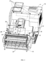
FIG. 2 is an overall schematic view of an image acquisition device for an agricultural harvesting operation machine of a preferred embodiment according to the present disclosure. -
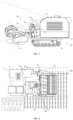
FIG. 3 is a side schematic view of the image acquisition device for the agricultural harvesting operation machine of the above-mentioned preferred embodiment according to the present disclosure. -
FIG. 4 is a partial schematic view of the image acquisition device for the agricultural harvesting operation machine of the above-mentioned preferred embodiment according to the present disclosure. -
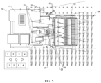
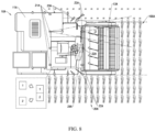
FIG. 5 is a partial schematic view of the image acquisition device for the agricultural harvesting operation machine of the above-mentioned preferred embodiment according to the present disclosure. -
FIG. 6 is a partial schematic view of the image acquisition device for the agricultural harvesting operation machine of the above-mentioned preferred embodiment according to the present disclosure. -
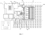
FIG. 7 is a flowchart of an image processing method for the agricultural harvesting operation machine of the above-mentioned preferred embodiment according to the present disclosure. -
FIG. 8 is a partial flowchart of the image processing method for the agricultural harvesting operation machine in another way of the above-mentioned preferred embodiment according to the present disclosure. -
FIG. 9 is a partial flowchart of the image processing method for the agricultural harvesting operation machine in the above-mentioned way of the above-mentioned preferred embodiment according to the present disclosure. -
FIG. 10 is an application schematic view of the image acquisition device and the image processing method for the agricultural harvesting operation machine of the above-mentioned preferred embodiment according to the present disclosure. - The following description is used to disclose the present disclosure so that one skilled in the art can implement the present disclosure. The preferred embodiments in the following description are only examples, and one skilled in the art can think of other obvious variations. The basic principles of the present disclosure defined in the following description can be applied to other embodiments, modified embodiments, improvement embodiments, equivalent embodiments, and other technical solutions that do not deviate from the scope as defined in the appended claims.
- One of ordinary skill in the art should understand that, according to the present disclosure, the orientation or position relationship indicated by the terms "longitudinal", "lateral", "upper", "lower", "front", "rear", "left", "right", "vertical", "horizontal", "top", "bottom", "inner", "outer", etc., is the orientation or position relationship shown in the drawings, which is convenient for describing the present disclosure and simplifying the description, rather than indicating or implying that the referred device or component must have a specific orientation, be constructed and operated in a specific orientation, the above terms should not be understood as limiting the present disclosure.
- It can be understood that, the term "a" should be understood as "at least one" or "one or more", that is, in one embodiment, the number of a component may be one, and in another embodiment, the number of the component may also be multiple, the term "one" cannot be understood as a restriction on the number.
- The present disclosure provides an image acquisition device and an image processing method for an agricultural harvesting operation machine, to acquire and process state information in agricultural harvesting operations in real time, provide a direct data source for subsequent control and supervision, and provide basis for optimization of operation efficiency.
- A preferred embodiment of the present disclosure is illustrated in
FIGS. 2-10 , the agricultural harvesting operation machine includes amachine body 10 and animage capturing assembly 20, theimage capturing assembly 20 is installed on a surface of themachine body 10. As shown inFIGS. 4-9 , when themachine body 10 is activated for harvesting operations, anoperation area 100 is formed in front of themachine body 10, and themachine body 10 only performs the harvesting operations in theoperation area 100. One of ordinary skill in the art can understand that, the harvesting operations of themachine body 10 sequentially performs operations including cutting, conveying, threshing, storing etc. of crops while moving forward. In other words, theoperation area 100 of themachine body 10 includes not only crops being harvested, but also crops that have been harvested and crops to be harvested, and theoperation area 100 is moveable. - The
image capturing assembly 20 is installed on themachine body 10 in a covering manner, and acquires images toward theoperating area 100. In other words, an acquiring range of theimage capturing assembly 20 covers a front and sides of themachine body 10. It is worth mentioning that, the harvested operations have been saved by themachine body 10. Theimage capturing assembly 20 acquires the images of theoperation area 100 including the crops being harvested and the crops to be harvested. In the preferred embodiment, theimage capturing assembly 20 is installed on the front and both sides of themachine body 10. That is, theimage capturing assembly 20 acquires the images of theoperation area 100 in a manner around front of theoperation area 100. - It is worth mentioning that, the images acquired by the
image capturing assembly 20 basically covers theoperating area 100. The images acquired from theimage capturing assembly 20 can reflect images around themachine body 10, and after being further processed, the acquired images can express the state information of theoperating area 100. - In some embodiments, the images acquired by the
image capturing assembly 20 may be multiple copies, and the images provided by output of theimage capturing assembly 20 are one of the multiple copies. In some embodiments, the output of theimage capturing assembly 20 is the state information of theoperation area 100. The state of themachine body 10 in operation is acquired according to the images acquired by theimage capturing assembly 20. - Referring to
FIG. 2 , the image acquisition device includes theimage capturing assembly 20 and acommunication device 30, thecommunication device 30 is communicatively connected with theimage capturing assembly 20 and acquires image information from theimage capturing assembly 20. The image acquisition device is installed in themachine body 10. When themachine body 10 performs the harvesting operations, theimage capturing assembly 20 acquires the images of theoperating area 100, and thecommunication device 30 uploads the information provided by theimage capturing assembly 20. In some embodiments, thecommunication device 30 transmits a copy of images provided by theimage capturing assembly 20 to a remote monitoring terminal to ensure real-time transmission. In some embodiments, thecommunication device 30 transmits processed information of the image acquired by theimage capturing assembly 20 to a remote control terminal to ensure a transmission speed. - In the preferred embodiment, the
image capturing assembly 20 is distributed on the front and the sides of themachine body 10. The multiple copies of images acquired by theimage capturing assembly 20 are spliced, and then transmitted through thecommunication device 30. - In detail, as illustrated in
FIGS. 2-3 , themachine body 10 includes abody frame 11, at least onewheel frame 12, and aharvesting frame 13, theharvesting frame 13 is arranged at a front of thebody frame 11, thewheel frame 12 is supported on a bottom of thebody frame 11. Thewheel frame 12 is operated to drive theharvesting frame 13 and thebody frame 11 forward to cut and transport the crops in front. The image acquisition device is arranged on thebody frame 11 of the agricultural harvesting operation machine. More specifically, theimage capturing assembly 20 is arranged on thebody frame 11, and theimage capturing assembly 20 acquires the images towards the operatingarea 100, and avoids acquiring images of thewheel frame 12 and theharvesting frame 13. - Further, in the preferred embodiment, the
image capturing assembly 20 includes a number of acquisition devices and aprocessor 24. The number of acquisition devices of theimage capturing assembly 20 are pre-installed on the front and sides of thebody frame 11 in a predetermined orientation. The images acquired by the acquisition devices are processed, summarized, and analyzed by theprocessor 24. In some embodiments, theprocessor 24 performs image processing according to the positions where the acquisition devices are installed. - In detail, the acquisition devices may be implemented as a number of wide-angle cameras, or may be implemented as a panoramic camera. In the preferred embodiment, The acquisition devices, as illustrated in
FIG. 3 , are installed in a distributed manner and classified as a distantview acquisition device 21, at least one closeview acquisition device 22, and at least one sideview acquisition device 23. The distantview acquisition device 21 and the closeview acquisition device 22 are adapted to thebody frame 11 and forward facing, and face an upper side and a lower side of theharvesting frame 13 respectively. More specifically, the distantview acquisition device 21 acquires images along the upper side of thewheel frame 12, and the closeview acquisition device 22 acquires images along positions between thewheel frame 12 and thewheel frame 12. The sideview acquisition devices 23 are respectively installed on both sides of thebody frame 11, and acquire images of crop state on both sides. - That is, the images acquired by the distant
view acquisition device 21 are related to the state of the crops to be harvested, and the images acquired by the closeview acquisition device 22 are related to the crops being harvested. The images acquired by the sideview acquisition device 23 are related to the position of theoperation area 100. - In some embodiments, the distant
view acquisition device 21, the closeview acquisition device 22, and the sideview acquisition device 23 are respectively numbered according to the installed positions. Theprocessor 24 acquires the position of the corresponding acquisition device according to each different number, and processes the images according to the acquired positions of the images. Since the processing is based on a position source of the image, the processing speed is increased. Especially for image splicing processing, based on the installed positions of the distantview acquisition device 21, the closeview acquisition device 22, and the sideview acquisition device 23, the images around themachine body 10 can be acquired quickly, thereby acquiring the state of theoperating area 100. In particular, based on different position types of the distantview acquisition device 21, the closeview acquisition device 22, and the sideview acquisition device 23, thebody frame 11, thewheel frame 12, and theharvesting frame 13 in the acquired images can be omitted by default. For example, a lower edge of the image acquired by the distantview acquisition device 21 may be regarded as theharvesting frame 13, and the lower edge is pre-cut or omitted in the processing process. For example, an upper edge of the image acquired by the closeview acquisition device 22 can be regarded as theharvesting frame 13, and a lower edge can be regarded as thewheel frame 12, so as to acquire state information of the crop being harvesting. For example, a lower edge of the image acquired by the sideview acquisition device 23 can be regarded as thewheel frame 12, so that part of themachine body 10 can be excluded. Therefore, the images acquired by the distantview acquisition device 21, the closeview acquisition device 22, and the sideview acquisition device 23 are quickly and preliminarily processed and spliced by theprocessor 24, to acquire the state information of theoperation area 100. - In detail, an image processing method of the preferred embodiment is shown in
FIGS. 4-6 . The image processing method for the agricultural harvesting operation machine includes the following steps: - I. Acquire a number of copies of images of the front and sides of the
machine body 10; - II. Splice the images according to positions in the acquired images; and
- III. Acquire state information around the
machine body 10 according to the spliced image. - In detail, as illustrated in
FIG. 5 , in the preferred embodiment, a number of the distantview acquisition devices 21 acquires the images toward the upper side of theharvesting frame 13. A number of the distantview acquisition devices 21 are installed at a certain interval, so that theoperation area 100 at the front of themachine body 10 is covered. That is, the number of the distantview acquisition devices 21 acquires the images for the crops to be harvested, which is the step I. - Then, according to the installed positions of the number of distant
view acquisition devices 21, the acquired images are sequentially spliced, so that the images of the crops to be harvested in front of theharvesting frame 13 are acquired. It is worth mentioning that, unlike the existing image splicing, there is no need to recognize each image to determine content of the image, but to splice a number of images directly according to the installed positions or theharvesting frame 13 in each image. Thus, an overall image of the front of themachine body 10 is acquired, which is the step II. - Then in step III, according to the overall image of the front of the
machine body 10 acquired by the distantview acquisition device 21, theoperating area 100 in front of themachine body 10 is acquired in real time and state information is represented. In some embodiments, the acquired images can be further analyzed in detail later. - In detail, as illustrated in
FIG. 4 , in the preferred embodiment, a number of closeview acquisition devices 22 acquires the images between the bottom of theharvesting frame 13 and thewheel frame 12. A number of closeview acquisition devices 22 are installed at a certain interval, so that theoperation area 100 in the middle of themachine body 10 is covered. That is, a number of closeview acquisition devices 22 acquires the images for the crops being harvested, which is step I. - Then, according to the installed positions of the number of close
view acquisition devices 22, the acquired images are sequentially spliced, so that the images of the crops being harvested under theharvesting frame 13 are acquired. It is worth mentioning that, unlike the existing image splicing, there is no need to recognize each image to determine content of the image, but to splice a number of images directly according to the installed positions or theharvesting frame 13 in each image. Thus, an overall image of the workingmachine body 10 is acquired, which is step II. - Then, according to the overall image of the working
machine body 10 acquired by the closeview acquisition devices 22, a harvesting state of themachine body 10 in theoperation area 100 is acquired and represented in real time, which is step III. In some embodiments, the acquired images can be further analyzed in detail later. - In detail, as illustrated in
FIG. 6 , in the preferred embodiment, a number of sidescene acquisition devices 23 acquire the images toward both sides of themachine body 10. The number of sidescene acquisition devices 23 are respectively installed on the left and right sides of themachine body 10, so that the state of the crops on both sides of themachine body 10 can be acquired. That is, generally, the sidescene acquisition devices 23 acquire images of a field that has been harvested and a field to be harvested respectively, which is step I. - Then, according to the installed positions of the number of side
scene acquisition devices 23, the acquired images are sequentially spliced, so that the images of the field that has been harvested and the field to be harvested are acquired. It is worth mentioning that, unlike existing image splicing, there is no need to recognize each image to determine content of the image, but to directly acquire the state of the crops that have been harvested according to the installed positions, such as the sideview acquisition devices 23 installed on the left side of themachine body 10, and to acquire the state of the crops to be harvested according to the sideview acquisition devices 23 installed on the right side of themachine body 10, so as to acquire the state of the crops on the left and right sides of the workingmachine body 10, the position of themachine body 10 is thus determined, which is step II. - Then in step III, according to the images of the sides of the
machine body 10 acquired by the sideview acquisition devices 23, a forward direction and a speed of themachine body 10 can be acquire, thereby ensuring accuracy of the forward direction of harvesting, and helping improve harvesting efficiency. - Furthermore, the images acquired by the distant
view acquisition devices 21, the closeview acquisition devices 22, and the sideview acquisition devices 23 are finally spliced together, to acquire the image of themachine body 10 in theoperation area 100. As illustrated inFIG. 7 , the state of the three sides of themachine body 10 is comprehensively acquired. In some embodiments, theimage capturing assembly 20 finally obtains an observation angle similar to that of themachine body 10 from top to bottom, which includes the crops being harvested, the crops to be harvested, and the position of the harvesting operation in the field. - Further, the image processing method, after step III, further includes the steps:
Transmit the state information of themachine body 10 remotely. - As illustrated in
FIG. 10 , an operation state of themachine body 10 can be acquired remotely. Further, themachine body 10 is remotely controlled for parameters in the harvesting operation. For example, a certain difference between the crops and theharvesting frame 13 is determined according to the images acquired by the closeview acquisition devices 22 and the sideview acquisition device 23, that is, the operation of themachine body 10 is relatively deviated from a required crop area, theharvesting frame 13 is required to be fully filled, to achieve high-efficiency harvesting. More specifically, for example, 80% of the left side of theharvesting frame 13 is determined to be harvesting crops according to the feedback image, then the state information can be acquired remotely, and the forward direction of themachine body 10 can be adjusted to the left, so that theharvesting frame 13 can fully cover the crops to be harvested. - Of course, operation adjustments of the
machine body 10 can be manually operated remotely, or can be adjusted by a predetermined program, and the images acquired by the image acquisition device can help control so as to realize unmanned agricultural production. - An image acquisition device for an agricultural harvesting operation machine of another feasible way of the above-mentioned preferred embodiment of the present disclosure is set forth, as illustrated in
FIGS. 8-9 , the agricultural harvesting operation machine includes amachine body 10A and animage capturing assembly 20A, structures of themachine body 10A and theimage capturing assembly 20A are similar with themachine body 10 and theimage capturing assembly 20 of the agricultural harvesting operation machine in the above-mentioned preferred embodiment, and is not repeated in the present disclosure. - The difference from the above-mentioned embodiment is that,
FIGS. 4-6 illustrate image splicing according to the same installed positions, and finally three different distantview acquisition devices 21A, closeview acquisition device 22A, and sideview acquisition devices 23A composite the final image. In the embodiment, according to the positions of the distantview acquisition device 21A, the closeview acquisition device 22A, and the sideview acquisition device 23A, the images acquired by the acquisition devices with similar positions are spliced, and then subsequently processed to be the final image. - The images acquired by the distance
view acquisition device 21A and the closeview acquisition device 22A located at the upper side and the lower side of theharvesting frame 13A are spliced first. As illustrated inFIG. 8 , the installed positions of a number of distanceview acquisition devices 21A and a number of closeview acquisition devices 22A are considered to be adjacent to each other. In other words, the distantview acquisition devices 21A and the closeview acquisition devices 22A acquire images of the crops to be harvested and the crops being harvested at the same position relative to theharvesting frame 13A, which is the step I. - Then, according to the installed positions of the distant
view acquisition device 21A and the closeview acquisition device 22A located above and below theharvesting frame 13A, the acquired images are sequentially spliced, so that the images of the upper side and the lower side of theharvesting frame 13A are acquired. It is worth mentioning that, unlike the existing image splicing, there is no need to recognition each image to determine content of the image, but directly to acquire an overall image of the crops before and after being cut at a certain position of themachine body 10A according to the installed positions, which is the step II. - Then in step III, according to an image of a certain position of the
machine body 10A, theoperation area 100A in front of themachine body 10A is acquired in real time and the state information is represented. In some embodiments, the acquired images can be further analyzed in detail later, which are similar to a viewing angle of traditional manual cutting. - In addition, The images acquired by the close
view acquisition device 22A located below an end of theharvesting frame 13A and the sideview acquisition device 23A located at an edge of the end of theharvesting frame 13A are spliced first. As illustrated inFIG. 9 , the installed positions of the sideview acquisition devices 23A and a number of closeview acquisition devices 22A are considered to be adjacent to each other. That is, the sideview acquisition device 23A and the closeview acquisition device 22A acquire images of the crops being harvested and the crops that have been harvested located the end of theharvesting frame 13A, which is the step I. - Then, according to the installed positions of the close
view acquisition device 22A located below the end of theharvesting frame 13A and the sideview acquisition device 23A located at the edge of the end, the acquired images are sequentially spliced, so that the images of the end of theharvesting frame 13A are acquired. It is worth mentioning that, unlike the existing image splicing, there is no need to recognize each image to determine content of the image, but to directly acquire an overall image of the crops before and after being cut at a certain position of themachine body 10A according to the installed positions, which is the step II. - Then in step III, according to the overall image of the certain position of the
machine body 10A, theoperating area 100A in front of themachine body 10A is acquired in real time and the state information is represented. In some embodiments, the acquired images can be further analyzed in detail later, which are similar to the viewing angle of traditional manual cutting. In the embodiment, an edge working state of themachine body 10A is further acquired, which is convenient for assisting in adjusting the operation position and the operation speed of themachine body 10A. - It is worth mentioning that, the images acquired by all the acquisition devices, including the distant
view acquisition device 21A, the closeview acquisition device 22A, and the sideview acquisition device 23A, are finally spliced together, so as to acquire an image of theoperation area 100A of themachine body 10A. As illustrated inFIG. 7 , the state before and after operation of themachine body 10A is comprehensively acquired. In some embodiments, theimage capturing assembly 20A finally acquire an observation angle similar to that of themachine body 10A from top to bottom, including the crops being harvested, the crops to be harvested, and the position of the harvesting operation in the field. - As illustrated in
FIG. 10 , the working state of themachine body 10A in the embodiment can be acquired remotely. Further, themachine body 10A is remotely controlled for parameters in the harvesting operation. For example, a certain difference between the crops and theharvesting frame 13 is determined according to the images acquired by the closeview acquisition devices 22A and the sideview acquisition device 23A, that is, the operation of themachine body 10 is relatively deviated from a required crop area, theharvesting frame 13 is required to be fully filled, to achieve high-efficiency harvesting. More specifically, for example, the crops that are not harvested at the left side of theharvesting frame 13 are determined and displayed in the sideview acquisition device 23A according to the feedback image, then the state information can be acquired remotely, and the forward direction of themachine body 10 can be adjusted to the left, so that theharvesting frame 13 can fully cover the crops to be harvested. - One of ordinary skill in the art should understand that, the above description and the embodiments of the present disclosure shown in the drawings are only examples and do not limit the present disclosure. The purpose of the present disclosure has been completely and effectively achieved. The functions and structural principles of the present disclosure have been shown and explained in the embodiments. Without departing from the principles, the embodiments of the present disclosure may have any deformation or modification within the scope of the appended claims.
Claims (15)
- An agricultural harvesting operation machine, comprising:a machine body (10) and an image capturing assembly (20), wherein the image capturing assembly (20) comprises a plurality of acquisition devices and a processor (24); the plurality of acquisition devices of the image capturing assembly is arranged on front and sides of the body frame with predetermined orientations;wherein the plurality of acquisition devices comprises:a plurality of distant view acquisition devices (21), at least one close view acquisition device (22), and at least two side view acquisition devices (23);wherein the plurality of distant view acquisition devices (21) and the at least one close view acquisition device (22) are adapted to be arranged on the body frame (11) forward facing, and face above and below the harvesting frame (13) respectively; andwherein the side view acquisition devices (23) are respectively arranged on both sides of the body frame (11), and face away from both sides of the machine body (10); wherein the machine comprises a controller, configured to form an operation area (100) in front of the machine body (10) in response to an activation of the machine body (10) for performing harvesting operations;wherein an acquiring range of the image capturing assembly (20) is arranged on the machine body (10) covering the machine body (10), and the image capturing assembly (20) is configured to acquire images toward the operating area (100), the image acquisition devices (20) placed on the machine body and configured to capture images of the operation area (100);wherein the machine body (10) comprises a body frame (11), a harvesting frame (13), and at least one wheel frame (12), the harvesting frame (13) being arranged in front of the body frame (11), the at least one wheel frame (12) being supported on a bottom of the body frame (11); andwherein the at least one wheel frame (12) is operated to drive the harvesting frame (13) and the body frame (11) forward to cut and transport crops in front.characterized in that, the plurality of acquisition devices is respectively numbered according to arranged positions, and the processor (24) is configured to acquire the position of each of the acquisition devices according to each number, and is configured to acquire images of crops to be harvested in front of the harvesting frame (13) according to the position of the each of the acquisition devices, and is configured to sequentially splice images acquired by the plurality of acquisition devices according to the position of each of the plurality of acquisition devices, and is configured to acquire an overall image of a front of the machine body (10).
- The agricultural harvesting operation machine according to claim 1, wherein at least one of the plurality of acquisition devices is implemented as a panoramic camera.
- The agricultural harvesting operation machine according to claim 1, wherein at least one of the plurality of acquisition devices is implemented as a wide-angle camera.
- The agricultural harvesting operation machine according to claim 3, wherein the processor (24) processes the images according to arranged positions of the plurality of acquisition devices.
- The agricultural harvesting operation machine according to claim 1, wherein the distant view acquisition devices (21) keep an orientation along an upper side of the at least one wheel frame (12), and the close view acquisition device (22) keeps an orientation along positions between the at least one wheel frame (12).
- The agricultural harvesting operation machine according to claim 1, wherein the plurality of distant view acquisition devices (21) is arranged at a certain interval, and a plurality of close view acquisition devices (22) is arranged at another certain interval.
- The agricultural harvesting operation machine according to claim 1, wherein the processor (24) processes the images according to the arranged positions of the plurality of acquisition devices, the images acquired by the close view acquisition devices (22) are preferentially spliced, and the images acquired by other acquisition devices are further spliced.
- The agricultural harvesting operation machine according to claim 1, wherein the processor (24) processes the images according to the arranged positions of the acquisition devices, the images acquired by the distant view acquisition devices (21) are preferentially spliced, and the images acquired by other acquisition devices are further spliced.
- The agricultural harvesting operation machine according to claim 1, wherein the images acquired by the plurality of acquisition devices which are adjacent to each other are preferentially spliced, and the images acquired by other acquisition devices are further spliced.
- The agricultural harvesting operation machine according to claim 9, wherein the images acquired by the distant view acquisition devices (21) and the close view acquisition devices (22) located above and below the harvesting frame (13) are preferentially spliced.
- The agricultural harvesting operation machine according to claim 9, wherein the images acquired by the distant view acquisition devices (21) located below an end of the harvesting frame (13) and the side view acquisition devices (23) located at an edge of the end are preferentially spliced.
- An image processing method for an agricultural harvesting operation machine, comprising:acquiring a plurality of images of a front and sides of a machine body (10), wherein the plurality of images is acquired from a plurality of acquisition devices, and the plurality of acquisition devices are respectively numbered according to arranged positions;characterized in that, acquiring the arranged positions of the plurality of acquisition devices according to each number;sequentially splicing the plurality of image according to the arranged position of each of the plurality of acquisition devices, and acquiring an overall image of a front of the machine body (10); andacquiring state information around the machine body (10) according to the spliced image.
- The image processing method according to claim 14, the method further comprising: transmitting the state information of the machine body (10) remotely.
- The image processing method according to claim 14, wherein splicing the plurality of images further comprising:
splicing preferentially the images acquired by the plurality of acquisition devices with similar orientations. - The image processing method according to claim 14, wherein splicing the plurality of images further comprising:
splicing preferentially the images acquired by the plurality of acquisition devices which are adjacent to each other.
Applications Claiming Priority (3)
| Application Number | Priority Date | Filing Date | Title |
|---|---|---|---|
| CN201910280375.0A CN110209155B (en) | 2019-04-09 | 2019-04-09 | Image acquisition device for agricultural cutting operation machine and processing method thereof |
| CN201920473543.3U CN210466135U (en) | 2019-04-09 | 2019-04-09 | Agricultural cutting machine |
| PCT/CN2020/080322 WO2020207225A1 (en) | 2019-04-09 | 2020-03-20 | Image acquisition device and processing method for agricultural harvesting operation machine |
Publications (3)
| Publication Number | Publication Date |
|---|---|
| EP3954190A1 EP3954190A1 (en) | 2022-02-16 |
| EP3954190A4 EP3954190A4 (en) | 2023-01-04 |
| EP3954190B1 true EP3954190B1 (en) | 2025-07-09 |
Family
ID=72751525
Family Applications (1)
| Application Number | Title | Priority Date | Filing Date |
|---|---|---|---|
| EP20788625.0A Active EP3954190B1 (en) | 2019-04-09 | 2020-03-20 | Image acquisition device and processing method for agricultural harvesting operation machine |
Country Status (6)
| Country | Link |
|---|---|
| US (1) | US12471528B2 (en) |
| EP (1) | EP3954190B1 (en) |
| JP (1) | JP7397880B2 (en) |
| AU (1) | AU2020256953B2 (en) |
| CA (1) | CA3135646A1 (en) |
| WO (1) | WO2020207225A1 (en) |
Families Citing this family (1)
| Publication number | Priority date | Publication date | Assignee | Title |
|---|---|---|---|---|
| CN117765085B (en) * | 2024-02-22 | 2024-06-07 | 华南农业大学 | Tea bud leaf picking far and near alternate positioning method |
Family Cites Families (17)
| Publication number | Priority date | Publication date | Assignee | Title |
|---|---|---|---|---|
| JP4744823B2 (en) | 2004-08-05 | 2011-08-10 | 株式会社東芝 | Perimeter monitoring apparatus and overhead image display method |
| JP2010029135A (en) * | 2008-07-30 | 2010-02-12 | Iseki & Co Ltd | Display device of combine harvester |
| JP5068779B2 (en) | 2009-02-27 | 2012-11-07 | 現代自動車株式会社 | Vehicle surroundings overhead image display apparatus and method |
| US9345194B2 (en) * | 2009-09-30 | 2016-05-24 | Cnh Industrial America Llc | Automatic display of remote camera image |
| JP2014117243A (en) | 2012-12-18 | 2014-06-30 | Yanmar Co Ltd | Combine harvester |
| CN105682446B (en) * | 2013-10-01 | 2018-06-08 | 洋马株式会社 | Combine harvester |
| JP2015070799A (en) * | 2013-10-01 | 2015-04-16 | ヤンマー株式会社 | Combine |
| US9911454B2 (en) * | 2014-05-29 | 2018-03-06 | Jaunt Inc. | Camera array including camera modules |
| JP6163460B2 (en) | 2014-06-30 | 2017-07-12 | ヤンマー株式会社 | Accompanying work system |
| JP2017086048A (en) | 2015-11-17 | 2017-05-25 | 井関農機株式会社 | Combine-harvester |
| CN105991929A (en) | 2016-06-21 | 2016-10-05 | 浩云科技股份有限公司 | Extrinsic parameter calibration and whole-space video stitching method for whole-space camera |
| WO2017221641A1 (en) | 2016-06-22 | 2017-12-28 | コニカミノルタ株式会社 | Plant growth index measurement device, method, and program |
| US10209718B2 (en) * | 2017-03-14 | 2019-02-19 | Starsky Robotics, Inc. | Vehicle sensor system and method of use |
| JP2018186728A (en) | 2017-04-28 | 2018-11-29 | 井関農機株式会社 | Combine |
| US10757859B2 (en) * | 2017-07-20 | 2020-09-01 | Deere & Company | System for optimizing platform settings based on crop state classification |
| CN210130123U (en) * | 2019-01-04 | 2020-03-10 | 丰疆智能科技股份有限公司 | Harvester with tripod head camera device |
| CN110209155B (en) * | 2019-04-09 | 2024-07-16 | 丰疆智能科技股份有限公司 | Image acquisition device for agricultural cutting operation machine and processing method thereof |
-
2020
- 2020-03-20 US US17/602,726 patent/US12471528B2/en active Active
- 2020-03-20 AU AU2020256953A patent/AU2020256953B2/en active Active
- 2020-03-20 EP EP20788625.0A patent/EP3954190B1/en active Active
- 2020-03-20 WO PCT/CN2020/080322 patent/WO2020207225A1/en not_active Ceased
- 2020-03-20 JP JP2021559955A patent/JP7397880B2/en active Active
- 2020-03-20 CA CA3135646A patent/CA3135646A1/en active Pending
Also Published As
| Publication number | Publication date |
|---|---|
| US20220167555A1 (en) | 2022-06-02 |
| EP3954190A1 (en) | 2022-02-16 |
| CA3135646A1 (en) | 2020-10-15 |
| JP2022528260A (en) | 2022-06-09 |
| EP3954190A4 (en) | 2023-01-04 |
| US12471528B2 (en) | 2025-11-18 |
| AU2020256953A1 (en) | 2021-12-02 |
| AU2020256953B2 (en) | 2024-02-29 |
| WO2020207225A1 (en) | 2020-10-15 |
| JP7397880B2 (en) | 2023-12-13 |
Similar Documents
| Publication | Publication Date | Title |
|---|---|---|
| DE102014201203B4 (en) | Agricultural work vehicle with an aircraft and associated power supply | |
| EP3939403B1 (en) | System and method of assisted or automated unload synchronization | |
| US9345194B2 (en) | Automatic display of remote camera image | |
| US9313951B2 (en) | Optical image capture for controlling a position of a harvester transfer device | |
| JP2019028688A (en) | Autonomous combine harvester system | |
| EP3939407A1 (en) | System and method of assisted or automated grain unload synchronization | |
| WO2014093814A1 (en) | Predictive load estimation through forward vision | |
| US11864494B2 (en) | AI-optimized harvester configured to maximize yield and minimize impurities | |
| EP3970466A1 (en) | System and method for presenting the surroundings of an agricultural implement | |
| US20160366821A1 (en) | Crop mat measurement through stereo imaging | |
| DE102016202628A1 (en) | Sensor arrangement for monitoring the function of a header | |
| JP7587503B2 (en) | Harvester and its automatic operation method | |
| US20220124956A1 (en) | Machine-vision system for tracking and quantifying missed tassel during a detasseling operation | |
| CN205567135U (en) | Corn harvester numerical control system | |
| DE102024101821A1 (en) | SYSTEM AND PROCEDURES FOR EVALUATING AGRICULTURAL ACTIVITIES | |
| US12471528B2 (en) | Image acquisition device and processing method for agricultural harvesting operation machine | |
| JP6735047B1 (en) | Mowing work method | |
| JP2022119267A (en) | Agriculture support system, mobile body, and agriculture support method | |
| US12178155B2 (en) | System and method of assisted or automated grain unload synchronization | |
| CN110209155B (en) | Image acquisition device for agricultural cutting operation machine and processing method thereof | |
| CN210466135U (en) | Agricultural cutting machine | |
| CN114044139A (en) | Unmanned aerial vehicle and intelligent farm management method based on unmanned aerial vehicle | |
| JP6874893B2 (en) | Mowing work method | |
| JP7301737B2 (en) | work vehicle | |
| US20260053090A1 (en) | System and Method of Assisted Assembly of a Header in an Agricultural Harvester and Agricultural Harvester |
Legal Events
| Date | Code | Title | Description |
|---|---|---|---|
| STAA | Information on the status of an ep patent application or granted ep patent |
Free format text: STATUS: THE INTERNATIONAL PUBLICATION HAS BEEN MADE |
|
| PUAI | Public reference made under article 153(3) epc to a published international application that has entered the european phase |
Free format text: ORIGINAL CODE: 0009012 |
|
| STAA | Information on the status of an ep patent application or granted ep patent |
Free format text: STATUS: REQUEST FOR EXAMINATION WAS MADE |
|
| 17P | Request for examination filed |
Effective date: 20211108 |
|
| AK | Designated contracting states |
Kind code of ref document: A1 Designated state(s): AL AT BE BG CH CY CZ DE DK EE ES FI FR GB GR HR HU IE IS IT LI LT LU LV MC MK MT NL NO PL PT RO RS SE SI SK SM TR |
|
| DAV | Request for validation of the european patent (deleted) | ||
| DAX | Request for extension of the european patent (deleted) | ||
| REG | Reference to a national code |
Ref country code: DE Ref legal event code: R079 Free format text: PREVIOUS MAIN CLASS: A01D0041020000 Ipc: A01B0069000000 Ref document number: 602020054253 Country of ref document: DE |
|
| A4 | Supplementary search report drawn up and despatched |
Effective date: 20221206 |
|
| RIC1 | Information provided on ipc code assigned before grant |
Ipc: A01D 41/127 20060101ALI20221130BHEP Ipc: A01D 41/02 20060101ALI20221130BHEP Ipc: A01B 69/00 20060101AFI20221130BHEP |
|
| STAA | Information on the status of an ep patent application or granted ep patent |
Free format text: STATUS: EXAMINATION IS IN PROGRESS |
|
| 17Q | First examination report despatched |
Effective date: 20240506 |
|
| GRAP | Despatch of communication of intention to grant a patent |
Free format text: ORIGINAL CODE: EPIDOSNIGR1 |
|
| STAA | Information on the status of an ep patent application or granted ep patent |
Free format text: STATUS: GRANT OF PATENT IS INTENDED |
|
| INTG | Intention to grant announced |
Effective date: 20250303 |
|
| GRAS | Grant fee paid |
Free format text: ORIGINAL CODE: EPIDOSNIGR3 |
|
| GRAA | (expected) grant |
Free format text: ORIGINAL CODE: 0009210 |
|
| STAA | Information on the status of an ep patent application or granted ep patent |
Free format text: STATUS: THE PATENT HAS BEEN GRANTED |
|
| AK | Designated contracting states |
Kind code of ref document: B1 Designated state(s): AL AT BE BG CH CY CZ DE DK EE ES FI FR GB GR HR HU IE IS IT LI LT LU LV MC MK MT NL NO PL PT RO RS SE SI SK SM TR |
|
| P01 | Opt-out of the competence of the unified patent court (upc) registered |
Free format text: CASE NUMBER: APP_25856/2025 Effective date: 20250530 |
|
| REG | Reference to a national code |
Ref country code: GB Ref legal event code: FG4D |
|
| REG | Reference to a national code |
Ref country code: CH Ref legal event code: EP |
|
| REG | Reference to a national code |
Ref country code: IE Ref legal event code: FG4D |
|
| REG | Reference to a national code |
Ref country code: DE Ref legal event code: R096 Ref document number: 602020054253 Country of ref document: DE |
|
| REG | Reference to a national code |
Ref country code: NL Ref legal event code: MP Effective date: 20250709 |
|
| PG25 | Lapsed in a contracting state [announced via postgrant information from national office to epo] |
Ref country code: PT Free format text: LAPSE BECAUSE OF FAILURE TO SUBMIT A TRANSLATION OF THE DESCRIPTION OR TO PAY THE FEE WITHIN THE PRESCRIBED TIME-LIMIT Effective date: 20251110 |
|
| PG25 | Lapsed in a contracting state [announced via postgrant information from national office to epo] |
Ref country code: NL Free format text: LAPSE BECAUSE OF FAILURE TO SUBMIT A TRANSLATION OF THE DESCRIPTION OR TO PAY THE FEE WITHIN THE PRESCRIBED TIME-LIMIT Effective date: 20250709 |
|
| REG | Reference to a national code |
Ref country code: AT Ref legal event code: MK05 Ref document number: 1810872 Country of ref document: AT Kind code of ref document: T Effective date: 20250709 |
|
| PG25 | Lapsed in a contracting state [announced via postgrant information from national office to epo] |
Ref country code: IS Free format text: LAPSE BECAUSE OF FAILURE TO SUBMIT A TRANSLATION OF THE DESCRIPTION OR TO PAY THE FEE WITHIN THE PRESCRIBED TIME-LIMIT Effective date: 20251109 |
|
| PG25 | Lapsed in a contracting state [announced via postgrant information from national office to epo] |
Ref country code: NO Free format text: LAPSE BECAUSE OF FAILURE TO SUBMIT A TRANSLATION OF THE DESCRIPTION OR TO PAY THE FEE WITHIN THE PRESCRIBED TIME-LIMIT Effective date: 20251009 |
|
| REG | Reference to a national code |
Ref country code: LT Ref legal event code: MG9D |
|
| PG25 | Lapsed in a contracting state [announced via postgrant information from national office to epo] |
Ref country code: AT Free format text: LAPSE BECAUSE OF FAILURE TO SUBMIT A TRANSLATION OF THE DESCRIPTION OR TO PAY THE FEE WITHIN THE PRESCRIBED TIME-LIMIT Effective date: 20250709 |
|
| PG25 | Lapsed in a contracting state [announced via postgrant information from national office to epo] |
Ref country code: FI Free format text: LAPSE BECAUSE OF FAILURE TO SUBMIT A TRANSLATION OF THE DESCRIPTION OR TO PAY THE FEE WITHIN THE PRESCRIBED TIME-LIMIT Effective date: 20250709 |
|
| PG25 | Lapsed in a contracting state [announced via postgrant information from national office to epo] |
Ref country code: HR Free format text: LAPSE BECAUSE OF FAILURE TO SUBMIT A TRANSLATION OF THE DESCRIPTION OR TO PAY THE FEE WITHIN THE PRESCRIBED TIME-LIMIT Effective date: 20250709 |
|
| PG25 | Lapsed in a contracting state [announced via postgrant information from national office to epo] |
Ref country code: GR Free format text: LAPSE BECAUSE OF FAILURE TO SUBMIT A TRANSLATION OF THE DESCRIPTION OR TO PAY THE FEE WITHIN THE PRESCRIBED TIME-LIMIT Effective date: 20251010 |
|
| PG25 | Lapsed in a contracting state [announced via postgrant information from national office to epo] |
Ref country code: SE Free format text: LAPSE BECAUSE OF FAILURE TO SUBMIT A TRANSLATION OF THE DESCRIPTION OR TO PAY THE FEE WITHIN THE PRESCRIBED TIME-LIMIT Effective date: 20250709 |
|
| PG25 | Lapsed in a contracting state [announced via postgrant information from national office to epo] |
Ref country code: LV Free format text: LAPSE BECAUSE OF FAILURE TO SUBMIT A TRANSLATION OF THE DESCRIPTION OR TO PAY THE FEE WITHIN THE PRESCRIBED TIME-LIMIT Effective date: 20250709 |
|
| PG25 | Lapsed in a contracting state [announced via postgrant information from national office to epo] |
Ref country code: PL Free format text: LAPSE BECAUSE OF FAILURE TO SUBMIT A TRANSLATION OF THE DESCRIPTION OR TO PAY THE FEE WITHIN THE PRESCRIBED TIME-LIMIT Effective date: 20250709 Ref country code: BG Free format text: LAPSE BECAUSE OF FAILURE TO SUBMIT A TRANSLATION OF THE DESCRIPTION OR TO PAY THE FEE WITHIN THE PRESCRIBED TIME-LIMIT Effective date: 20250709 |
|
| PG25 | Lapsed in a contracting state [announced via postgrant information from national office to epo] |
Ref country code: RS Free format text: LAPSE BECAUSE OF FAILURE TO SUBMIT A TRANSLATION OF THE DESCRIPTION OR TO PAY THE FEE WITHIN THE PRESCRIBED TIME-LIMIT Effective date: 20251009 |
|
| PG25 | Lapsed in a contracting state [announced via postgrant information from national office to epo] |
Ref country code: ES Free format text: LAPSE BECAUSE OF FAILURE TO SUBMIT A TRANSLATION OF THE DESCRIPTION OR TO PAY THE FEE WITHIN THE PRESCRIBED TIME-LIMIT Effective date: 20250709 |
|
| PG25 | Lapsed in a contracting state [announced via postgrant information from national office to epo] |
Ref country code: SM Free format text: LAPSE BECAUSE OF FAILURE TO SUBMIT A TRANSLATION OF THE DESCRIPTION OR TO PAY THE FEE WITHIN THE PRESCRIBED TIME-LIMIT Effective date: 20250709 |
|
| PG25 | Lapsed in a contracting state [announced via postgrant information from national office to epo] |
Ref country code: DK Free format text: LAPSE BECAUSE OF FAILURE TO SUBMIT A TRANSLATION OF THE DESCRIPTION OR TO PAY THE FEE WITHIN THE PRESCRIBED TIME-LIMIT Effective date: 20250709 |
|
| PGFP | Annual fee paid to national office [announced via postgrant information from national office to epo] |
Ref country code: DE Payment date: 20260313 Year of fee payment: 7 |
|
| PG25 | Lapsed in a contracting state [announced via postgrant information from national office to epo] |
Ref country code: IT Free format text: LAPSE BECAUSE OF FAILURE TO SUBMIT A TRANSLATION OF THE DESCRIPTION OR TO PAY THE FEE WITHIN THE PRESCRIBED TIME-LIMIT Effective date: 20250709 |
|
| PGFP | Annual fee paid to national office [announced via postgrant information from national office to epo] |
Ref country code: FR Payment date: 20260330 Year of fee payment: 7 |
|
| PG25 | Lapsed in a contracting state [announced via postgrant information from national office to epo] |
Ref country code: CZ Free format text: LAPSE BECAUSE OF FAILURE TO SUBMIT A TRANSLATION OF THE DESCRIPTION OR TO PAY THE FEE WITHIN THE PRESCRIBED TIME-LIMIT Effective date: 20250709 |
|
| PG25 | Lapsed in a contracting state [announced via postgrant information from national office to epo] |
Ref country code: SK Free format text: LAPSE BECAUSE OF FAILURE TO SUBMIT A TRANSLATION OF THE DESCRIPTION OR TO PAY THE FEE WITHIN THE PRESCRIBED TIME-LIMIT Effective date: 20250709 Ref country code: EE Free format text: LAPSE BECAUSE OF FAILURE TO SUBMIT A TRANSLATION OF THE DESCRIPTION OR TO PAY THE FEE WITHIN THE PRESCRIBED TIME-LIMIT Effective date: 20250709 |
|
| PLBE | No opposition filed within time limit |
Free format text: ORIGINAL CODE: 0009261 |
|
| STAA | Information on the status of an ep patent application or granted ep patent |
Free format text: STATUS: NO OPPOSITION FILED WITHIN TIME LIMIT |