EP3951812A1 - Transformer core and transformer - Google Patents
Transformer core and transformer Download PDFInfo
- Publication number
- EP3951812A1 EP3951812A1 EP20189858.2A EP20189858A EP3951812A1 EP 3951812 A1 EP3951812 A1 EP 3951812A1 EP 20189858 A EP20189858 A EP 20189858A EP 3951812 A1 EP3951812 A1 EP 3951812A1
- Authority
- EP
- European Patent Office
- Prior art keywords
- elongate
- column
- transformer core
- clamping structure
- yoke
- Prior art date
- Legal status (The legal status is an assumption and is not a legal conclusion. Google has not performed a legal analysis and makes no representation as to the accuracy of the status listed.)
- Granted
Links
Images


Classifications
-
- H—ELECTRICITY
- H01—ELECTRIC ELEMENTS
- H01F—MAGNETS; INDUCTANCES; TRANSFORMERS; SELECTION OF MATERIALS FOR THEIR MAGNETIC PROPERTIES
- H01F27/00—Details of transformers or inductances, in general
- H01F27/24—Magnetic cores
- H01F27/26—Fastening parts of the core together; Fastening or mounting the core on casing or support
- H01F27/263—Fastening parts of the core together
-
- H—ELECTRICITY
- H01—ELECTRIC ELEMENTS
- H01F—MAGNETS; INDUCTANCES; TRANSFORMERS; SELECTION OF MATERIALS FOR THEIR MAGNETIC PROPERTIES
- H01F27/00—Details of transformers or inductances, in general
- H01F27/24—Magnetic cores
- H01F27/26—Fastening parts of the core together; Fastening or mounting the core on casing or support
-
- H—ELECTRICITY
- H01—ELECTRIC ELEMENTS
- H01F—MAGNETS; INDUCTANCES; TRANSFORMERS; SELECTION OF MATERIALS FOR THEIR MAGNETIC PROPERTIES
- H01F27/00—Details of transformers or inductances, in general
- H01F27/24—Magnetic cores
-
- H—ELECTRICITY
- H01—ELECTRIC ELEMENTS
- H01F—MAGNETS; INDUCTANCES; TRANSFORMERS; SELECTION OF MATERIALS FOR THEIR MAGNETIC PROPERTIES
- H01F27/00—Details of transformers or inductances, in general
- H01F27/24—Magnetic cores
- H01F27/245—Magnetic cores made from sheets, e.g. grain-oriented
-
- H—ELECTRICITY
- H01—ELECTRIC ELEMENTS
- H01F—MAGNETS; INDUCTANCES; TRANSFORMERS; SELECTION OF MATERIALS FOR THEIR MAGNETIC PROPERTIES
- H01F27/00—Details of transformers or inductances, in general
- H01F27/28—Coils; Windings; Conductive connections
- H01F27/30—Fastening or clamping coils, windings, or parts thereof together; Fastening or mounting coils or windings on core, casing, or other support
- H01F27/306—Fastening or mounting coils or windings on core, casing or other support
-
- H—ELECTRICITY
- H01—ELECTRIC ELEMENTS
- H01F—MAGNETS; INDUCTANCES; TRANSFORMERS; SELECTION OF MATERIALS FOR THEIR MAGNETIC PROPERTIES
- H01F27/00—Details of transformers or inductances, in general
- H01F27/33—Arrangements for noise damping
Definitions
- the present disclosure relates to a transformer core and, more particularly, to a transformer core having an improved stiffness. Further, the disclosure relates to a transformer comprising such a transformer core.
- a conventional transformer typically comprises windings mounted on cores of ferromagnetic material.
- the cores are connected at its lower ends to a bottom yoke and at its upper ends to a top yoke.
- the yokes and the columns are typically assembled as a stack of magnetic sheets, e.g. grain-oriented or grain-not-oriented magnetic sheets. Further, it is known to use a frame for clamping and compressing the bottom yoke together and the top yoke together.
- the structure of the transformer assembly i.e. the "transformer frame structure” may be displaced in such a way that high stress levels acting on critical parts of the assembly may arise. This may result in fatigue and crack propagation mechanisms and a failure of the transformer. Corresponding loads may occur for example in case of a transformer used in the field of nuclear power, wind power, marine and other industries.
- a transformer core comprising a first yoke, a second yoke, a column having a column main axis and extending between the first yoke and the second yoke, and an elongate clamping structure comprising an elongate rigid member having a rigid member main axis.
- the column includes an elongate opening having an opening main axis which is oriented transversal with respect to the column main axis.
- the rigid member is positioned within the elongate opening such that the rigid member main axis is oriented parallel to the opening main axis.
- the elongate clamping structure allows for effectuating a controllable stiffness of the column. In this manner the mechanical properties of the column and of the whole transformer core can be controlled or influenced.
- the stiffness of the column significantly influences the dynamic response of the transformer core and the dynamic response of the transformer to external loads such as vibrational or shock loads. Further, it influences the quality of a noise generated by the transformer core in response to such loads. More specifically, the elongate clamping structure allows for effectuating an enlarged stiffness of the transformer core resulting in an improved response behavior of the transformer to external loads.
- the stiffness of the transformer core plays a dominant role in the dynamic response of the transformer, particularly to vibrational loads.
- the structural stiffness of the transformer core directly influences the mechanical resonance behavior of the transformer core and the corresponding relevant mode shapes.
- a low mechanical overall resonance frequency leads to large displacements of the structure during vibration, and therefore to high stress levels on critical parts of the transformer frame structure.
- the stiffness and compactness of the columns of the core are primary factors with respect to the lowest and dominant mechanical resonances of the core. This is due to the ratio between the stiffness and the mass of a column which is insofar unfavorable.
- the most critical mode of vibration is the one involving a longitudinal bending of the columns, as schematically sketched in Figures 2a and 2b illustrating a side view of a transformer.
- the elongate clamping structure allows for achieving an increased flexural stiffness of the column and in this manner increased mechanical resonance frequencies of the transformer core resulting in reduced stress levels. Thus, a reduced risk of a failure of the transformer can be
- the column comprises a stack of sheets, e.g. grain-oriented or grain-not-oriented sheets.
- the elongate clamping structure is particularly suited in such a case, since it allows for reducing movements of the sheets relative to each other.
- the elongate clamping structure comprises a first end portion and an opposing second end portion, wherein the first and second end portions are configured to compress a portion of the column which surrounds the elongate clamping structure. This allows for effectuating a force which compresses or tightens the column. In this manner, the stiffness of the column can be further improved.
- the first end portion and/or the second end portion of the elongate clamping structure comprise(s) a fixing member having a conical shaped head portion.
- the conical shaped head portion helps generating a specifically effective compressing force.
- the fixing member for example comprises or is formed by a countersunk bolt.
- the elongate opening comprises at least one conical end portion which is shaped correspondent to the conical shaped head portion of the fixing member, wherein the transformer core is preferably designed such that the conical shaped head portion of the fixing member is positioned completely within the elongate opening.
- the transformer core is preferably designed such that the conical shaped head portion of the fixing member is positioned completely within the elongate opening.
- the column comprises at least one leg plate extending parallel to the column main axis, wherein the at least one conical end portion of the elongate opening is formed in the at least one leg plate.
- the fixing member comprises a screw which is screwable connected to the rigid member. This allows for achieving a controllable compressive force acting on the column in a particularly suitable and easy to handle manner. Moreover, this facilitates assembling of the transformer core.
- the transformer core further comprises at least one washer positioned around the conical shaped head portion of the fixing member.
- the washer is of insulating material. This allows for mitigating the risk of damaging parts of the transformer core during assembly.
- the elongate clamping structure comprises an insulation tube which is positioned between the rigid member and an inner surface of the elongate opening and configured to effectuate an isolation between the rigid member and the column.
- the insulation tube may be a flexible insulation tube.
- the washer is be formed as a part of the insulation tube.
- the insulation tube preferably extends to the outer end of the conical shaped head portion of the fixing member.
- the insulation tube is designed such that it ends flush with a surrounding outer surface section of the column directly adjacent to the conical end portion of the elongate opening.
- the washer is preferably positioned between the conical shaped head portion of the fixing member and the insulation tube.
- the insulation tube and the washer in any case are formed such that they do not protrude above the surrounding outer surface section of the column.
- the transformer core comprises at least one further elongate clamping structure which is constructed analog to the first mentioned elongate clamping structure.
- the elongate rigid member of the at least one further elongate clamping structure is oriented parallel to the elongate rigid member of the first mentioned elongate clamping structure.
- the at least one further elongate clamping structure allows for effectuating a further improved stiffness and compactness of the column.
- At least three elongate clamping structures are preferably provided such that a row of elongate clamping structures along the column is formed, comprising a first elongate clamping structure, a second elongate clamping structure, and a third elongate clamping structure, in that order, wherein a first distance between the first and the second elongate clamping structures differs from a second distance between the second and the third elongate clamping structures.
- the row of elongate clamping structures is formed such that the distances between the elongate clamping structures increase with increasing distance form the first yoke, wherein preferably, the first yoke is a bottom yoke and the second yoke is an upper yoke.
- the transformer core further comprises at least one further column, wherein a main axis of the at least one further column and the main axis of the first mentioned column are positioned within a common plane, and wherein the opening main axis of the elongate opening is further oriented normal to said plane.
- the at least one further column is constructed analog to the first mentioned column.
- the at least one further column comprises corresponding elongate openings, wherein rigid members of corresponding further elongate clamping structures are positioned within the elongate openings analogously.
- a transformer comprising a transformer core according to the disclosure and a winding wound around the column is provided.
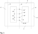
- Fig. 1 is a schematic front view of a transformer core according to the disclosure.
- a transformer comprising the transformer core may be for example a distribution transformer.
- the transformer core comprises a first yoke 2, a second yoke 4, and a column 6.
- the first yoke 2 is a lower or bottom yoke and the second yoke 4 is an upper yoke.
- the column 6 extends between the first yoke 2 and the second yoke 4.
- the column 6 has a column main axis 8 which is preferably oriented at least essentially vertically. A cross-section of the column 6 normal to the column main axis 8 is preferably at least to a first approximation circular.
- the transformer core further comprises at least one further column 6', 6", for example two further columns 6', 6", wherein a main axis 8', 8" of the at least one further column 6', 6" and the main axis 8 of the first mentioned column 6 are positioned within a common plane, for example a vertical plane.
- the at least one further column 6', 6" is preferably constructed analog to the first mentioned column 6.
- the transformer comprises the transformer core according to the disclosure and windings wound around each one of the columns 6, 6, 6".
- the transformer core further comprises an elongate clamping structure 10.
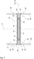
- Fig. 3 is a schematic cross-sectional view of the elongate clamping structure 10 and a surrounding portion of the column 6. Note that Fig. 3 shows the distances between corresponding parts enlarged simply for improved recognizability.
- the cross-section of Fig. 3 is taken perpendicular to the common plane in which the main axes 8, 8', 8" of the columns 6, 6', 6" are positioned, i.e. in a plane perpendicular to the drawing plane of Fig. 1 .
- the elongate clamping structure 10 comprises an elongate rigid member 12 having a rigid member main axis 14.
- the rigid member 12 is preferably made of a material comprising a metal, particularly steel.
- the rigid member 12 preferably is tube shaped, for example in the form of a hollow-core bolt.
- the rigid member 12 is a steel pipe in the form of a hollow-core bolt.
- the column 6 includes an elongate opening 16 having an opening main axis 18 which is oriented transversal, for example perpendicular with respect to the column main axis 8.
- the opening main axis 18 is oriented horizontally.
- the rigid member 12 is positioned within the elongate opening 16 such that the rigid member main axis 14 is oriented parallel to the opening main axis 18.
- Figures 2a and 2b are schematically illustrated side views of a prior art transformer core illustrating generally an effect of a load acting on the transformer core.
- the transformer core comprises a bottom yoke 200, a column 600, and an upper yoke 400.
- Fig. 2a illustrates a state of the transformer core without the load acting on the transformer core
- Fig. 2b a state with the load acting on the transformer core, as indicated by an arrow.
- the load leads to a deformation of the transformer core as shown in Fig. 2b which is generally unwanted since it involves an increased risk of a crack mechanism potentially leading to a failure of the transformer, as outlined above.
- the stiffness of the column and of the transformer core can be suitably increased under use of the elongate clamping structure in such a way that a corresponding unwanted deformation of the transformer core can be prevented.
- the elongate rigid member 12 is designed such that it extends over at least 80%, more preferably at least 90% of the length of the elongate opening 16. Preferably, both ends of the elongate rigid member 12 does not protrude beyond an outer surface of the column 6.
- the elongate clamping structure 10 comprises a first end portion 20 and an opposing second end portion 22.
- the first and second end portions 20, 22 are configured to compress a portion of the column 6 which surrounds the elongate clamping structure 10.
- the first end portion 20 and/or the second end portion 22 of the elongate clamping structure 10 comprises a fixing member 24, 24' having a conical shaped head portion 26, 26'.
- the fixing member 24, 24' is a countersunk bolt.
- the fixing member 24, 24' comprises or is formed of a screw which is screwable connected to the rigid member 12, for example screwed into the rigid member 12 having the form of a hollow-core bolt. This enables easy connecting the elongate clamping structure 10 to the column 6 during assembly of the transformer core.
- the elongate opening 16 comprises at least one conical end portion 30, 30' which is shaped correspondent to the conical shaped head portion 26, 26' of the fixing member 24, 24'. This allows for an easy and fine adjustment of a compressive force acting on the column 6 that is generated by the fixing members 24 in combination with the elongate rigid member 12.
- the column 6 preferably comprises at least one leg plate 66 extending parallel to the column main axis 8, wherein the at least one conical end portion 30, 30' is formed in the at least one leg plate 66.
- the leg plate 66 forms an outer surface of the column 6.
- the column 6 comprises a stack of sheets, wherein an inner surface of the at least one leg plate 66 abuts the stack of sheets.
- the column 6 comprises two leg plates 66 disposed on opposing sides of the column 6 with respect to the column main axis 8.
- the transformer core is preferably designed such that the conical shaped head portion 26, 26' of the fixing member 24, 24' is positioned completely within the elongate opening 16. Accordingly, an interference of a winding of a coil wound around the column 6 with the elongate clamping structure 10 can be precluded or at least mitigated.
- the elongate clamping structure 10 preferably further comprises an insulation tube 32 which is positioned between the rigid member 12 and an inner surface of the elongate opening 16 and configured to effectuate an isolation between the rigid member 12 and the column 6.
- the insulation tube 32 is made from a material comprising Polytetrafluorethylene (PTFE).
- PTFE Polytetrafluorethylene
- the insulation tube 32 is a PTFE-tube.
- the transformer core may further comprise at least one washer positioned around the conical shaped head portion 26, 26' of the fixing member 24, 24'.
- the at least one washer is arranged between the head portion 26, 26' of the fixing member 26, 26' and the conical end portion 30, 30' of the elongate opening 16.
- the at least one washer may be associated with the insulation tube 32 or formed as a part of the insulation tube 32.
- the at least one washer - here indicated by reference sign 34 - may be an insulatingwasher arranged between the head portion 26, 26' and a surface of the conical end portion 30, 30' of the elongate opening 16. This reduces the risk of damaging the insulation tube 32 during assembly, for example during tightening the fixing members 26, 26'.
- the transformer core preferably further comprises at least one further elongate clamping structure 10', 10", 10'” as exemplarily sketched in Fig. 1 , which is constructed analog to the first mentioned elongate clamping structure 10.
- the elongate rigid member of the at least one further elongate clamping structure 10', 10", 10'” is preferably oriented parallel to the elongate rigid member 12 of the first mentioned elongate clamping structure 10.
- the transformer core comprises at least three elongate clamping structures 10, 10', 10", 10'" such that a row of elongate clamping structures along the column 6 is formed, comprising a first elongate clamping structure 10, a second elongate clamping structure 10', and a third elongate clamping structure 10", in that order.
- a first distance d 1 between the first and the second elongate clamping structures 10, 10' differs from a second distance d 2 between the second and the third elongate clamping structures 10', 10".
- the row of elongate clamping structures 10, 10', 10", 10"' is formed such that the distances d 1 , d 2 , d 3 between the elongate clamping structures 10, 10', 10", 10"' increase with increasing distance form the first yoke 2.
Landscapes
- Engineering & Computer Science (AREA)
- Power Engineering (AREA)
- Coils Of Transformers For General Uses (AREA)
- Coils Or Transformers For Communication (AREA)
- Transformers For Measuring Instruments (AREA)
Abstract
Description
- The present disclosure relates to a transformer core and, more particularly, to a transformer core having an improved stiffness. Further, the disclosure relates to a transformer comprising such a transformer core.
- A conventional transformer typically comprises windings mounted on cores of ferromagnetic material. The cores are connected at its lower ends to a bottom yoke and at its upper ends to a top yoke. The yokes and the columns are typically assembled as a stack of magnetic sheets, e.g. grain-oriented or grain-not-oriented magnetic sheets. Further, it is known to use a frame for clamping and compressing the bottom yoke together and the top yoke together.
- However, in certain cases of dynamic loads, for example vibrational loads caused by a seismic activity, the structure of the transformer assembly, i.e. the "transformer frame structure" may be displaced in such a way that high stress levels acting on critical parts of the assembly may arise. This may result in fatigue and crack propagation mechanisms and a failure of the transformer. Corresponding loads may occur for example in case of a transformer used in the field of nuclear power, wind power, marine and other industries.
- There is a need to provide improved techniques for reducing the risk of a failure of a transformer. There is particularly a need for techniques that mitigate the risk of crack formations in a transformer frame structure. These objects are achieved by the independent claims. Dependent claims refer to preferred embodiments.
- According to the present disclosure, a transformer core, comprising a first yoke, a second yoke, a column having a column main axis and extending between the first yoke and the second yoke, and an elongate clamping structure comprising an elongate rigid member having a rigid member main axis is provided. The column includes an elongate opening having an opening main axis which is oriented transversal with respect to the column main axis. The rigid member is positioned within the elongate opening such that the rigid member main axis is oriented parallel to the opening main axis.
- The elongate clamping structure allows for effectuating a controllable stiffness of the column. In this manner the mechanical properties of the column and of the whole transformer core can be controlled or influenced. The stiffness of the column significantly influences the dynamic response of the transformer core and the dynamic response of the transformer to external loads such as vibrational or shock loads. Further, it influences the quality of a noise generated by the transformer core in response to such loads. More specifically, the elongate clamping structure allows for effectuating an enlarged stiffness of the transformer core resulting in an improved response behavior of the transformer to external loads.
- The stiffness of the transformer core plays a dominant role in the dynamic response of the transformer, particularly to vibrational loads. The structural stiffness of the transformer core directly influences the mechanical resonance behavior of the transformer core and the corresponding relevant mode shapes. Generally, a low mechanical overall resonance frequency leads to large displacements of the structure during vibration, and therefore to high stress levels on critical parts of the transformer frame structure. The stiffness and compactness of the columns of the core are primary factors with respect to the lowest and dominant mechanical resonances of the core. This is due to the ratio between the stiffness and the mass of a column which is insofar unfavorable. The most critical mode of vibration is the one involving a longitudinal bending of the columns, as schematically sketched in
Figures 2a and 2b illustrating a side view of a transformer. The elongate clamping structure allows for achieving an increased flexural stiffness of the column and in this manner increased mechanical resonance frequencies of the transformer core resulting in reduced stress levels. Thus, a reduced risk of a failure of the transformer can be achieved. - Various embodiments may preferably implement the following features:
Preferably, the column comprises a stack of sheets, e.g. grain-oriented or grain-not-oriented sheets. The elongate clamping structure is particularly suited in such a case, since it allows for reducing movements of the sheets relative to each other. - Preferably, the elongate clamping structure comprises a first end portion and an opposing second end portion, wherein the first and second end portions are configured to compress a portion of the column which surrounds the elongate clamping structure. This allows for effectuating a force which compresses or tightens the column. In this manner, the stiffness of the column can be further improved.
- Preferably, the first end portion and/or the second end portion of the elongate clamping structure comprise(s) a fixing member having a conical shaped head portion. The conical shaped head portion helps generating a specifically effective compressing force.
- Preferably, the fixing member for example comprises or is formed by a countersunk bolt.
- Preferably, the elongate opening comprises at least one conical end portion which is shaped correspondent to the conical shaped head portion of the fixing member, wherein the transformer core is preferably designed such that the conical shaped head portion of the fixing member is positioned completely within the elongate opening. Thus, an adverse effect of the fixing member on windings of a coil of the transformer which is wound about the column can be excluded or at least mitigated.
- Preferably, the column comprises at least one leg plate extending parallel to the column main axis, wherein the at least one conical end portion of the elongate opening is formed in the at least one leg plate.
- Preferably, the fixing member comprises a screw which is screwable connected to the rigid member. This allows for achieving a controllable compressive force acting on the column in a particularly suitable and easy to handle manner. Moreover, this facilitates assembling of the transformer core.
- Preferably, the transformer core further comprises at least one washer positioned around the conical shaped head portion of the fixing member.
- Preferably, the washer is of insulating material. This allows for mitigating the risk of damaging parts of the transformer core during assembly.
- Preferably, the elongate clamping structure comprises an insulation tube which is positioned between the rigid member and an inner surface of the elongate opening and configured to effectuate an isolation between the rigid member and the column. The insulation tube may be a flexible insulation tube.
- Preferably, the washer is be formed as a part of the insulation tube. In other words, the insulation tube preferably extends to the outer end of the conical shaped head portion of the fixing member. Preferably, the insulation tube is designed such that it ends flush with a surrounding outer surface section of the column directly adjacent to the conical end portion of the elongate opening. Alternatively, the washer is preferably positioned between the conical shaped head portion of the fixing member and the insulation tube. Preferably, the insulation tube and the washer in any case are formed such that they do not protrude above the surrounding outer surface section of the column.
- Preferably, the transformer core comprises at least one further elongate clamping structure which is constructed analog to the first mentioned elongate clamping structure. Preferably, the elongate rigid member of the at least one further elongate clamping structure is oriented parallel to the elongate rigid member of the first mentioned elongate clamping structure. The at least one further elongate clamping structure allows for effectuating a further improved stiffness and compactness of the column.
- For example, at least three elongate clamping structures are preferably provided such that a row of elongate clamping structures along the column is formed, comprising a first elongate clamping structure, a second elongate clamping structure, and a third elongate clamping structure, in that order, wherein a first distance between the first and the second elongate clamping structures differs from a second distance between the second and the third elongate clamping structures. This allows for achieving a certain level of stiffness and compactness of the column by a particularly small number of elongate clamping structures.
- Preferably, the row of elongate clamping structures is formed such that the distances between the elongate clamping structures increase with increasing distance form the first yoke, wherein preferably, the first yoke is a bottom yoke and the second yoke is an upper yoke.
- Preferably, the transformer core further comprises at least one further column, wherein a main axis of the at least one further column and the main axis of the first mentioned column are positioned within a common plane, and wherein the opening main axis of the elongate opening is further oriented normal to said plane.
- Preferably, the at least one further column is constructed analog to the first mentioned column. Preferably, the at least one further column comprises corresponding elongate openings, wherein rigid members of corresponding further elongate clamping structures are positioned within the elongate openings analogously.
- According to a further aspect of the disclosure, a transformer comprising a transformer core according to the disclosure and a winding wound around the column is provided.
- The subject-matter of the disclosure will be explained in more detail with reference to preferred exemplary embodiments which are illustrated in the attached drawings, in which:
-
Fig. 1 is a schematic frontal view of a transformer core comprising columns and yokes according to the disclosure. -
Figures 2a and 2b are schematic side views of a transformer core illustrating a longitudinal bending of the columns. -
Fig. 3 is a schematic cross-sectional view of an elongate clamping structure according to the disclosure. -
Fig. 4 illustrates a variation of the elongate clamping structure ofFig. 3 comprising a separately formed washer. - Example embodiments of the disclosure will be described with reference to the drawings in which identical or similar reference signs designate identical or similar elements. The features of embodiments may be combined with each other, unless specifically noted otherwise.
-
Fig. 1 is a schematic front view of a transformer core according to the disclosure. A transformer comprising the transformer core may be for example a distribution transformer. The transformer core comprises afirst yoke 2, asecond yoke 4, and acolumn 6. Thefirst yoke 2 is a lower or bottom yoke and thesecond yoke 4 is an upper yoke. Thecolumn 6 extends between thefirst yoke 2 and thesecond yoke 4. Thecolumn 6 has a columnmain axis 8 which is preferably oriented at least essentially vertically. A cross-section of thecolumn 6 normal to the columnmain axis 8 is preferably at least to a first approximation circular. - The transformer core further comprises at least one
further column 6', 6", for example twofurther columns 6', 6", wherein amain axis 8', 8" of the at least onefurther column 6', 6" and themain axis 8 of the first mentionedcolumn 6 are positioned within a common plane, for example a vertical plane. The at least onefurther column 6', 6" is preferably constructed analog to the first mentionedcolumn 6. The transformer comprises the transformer core according to the disclosure and windings wound around each one of thecolumns - The transformer core further comprises an
elongate clamping structure 10.Fig. 3 is a schematic cross-sectional view of theelongate clamping structure 10 and a surrounding portion of thecolumn 6. Note thatFig. 3 shows the distances between corresponding parts enlarged simply for improved recognizability. The cross-section ofFig. 3 is taken perpendicular to the common plane in which themain axes columns Fig. 1 . - The
elongate clamping structure 10 comprises an elongaterigid member 12 having a rigid member main axis 14. Therigid member 12 is preferably made of a material comprising a metal, particularly steel. Therigid member 12 preferably is tube shaped, for example in the form of a hollow-core bolt. For example, therigid member 12 is a steel pipe in the form of a hollow-core bolt. - The
column 6 includes anelongate opening 16 having an opening main axis 18 which is oriented transversal, for example perpendicular with respect to the columnmain axis 8. Preferably, the opening main axis 18 is oriented horizontally. Therigid member 12 is positioned within theelongate opening 16 such that the rigid member main axis 14 is oriented parallel to the opening main axis 18. -
Figures 2a and 2b are schematically illustrated side views of a prior art transformer core illustrating generally an effect of a load acting on the transformer core. The transformer core comprises abottom yoke 200, acolumn 600, and anupper yoke 400.Fig. 2a illustrates a state of the transformer core without the load acting on the transformer core,Fig. 2b a state with the load acting on the transformer core, as indicated by an arrow. The load leads to a deformation of the transformer core as shown inFig. 2b which is generally unwanted since it involves an increased risk of a crack mechanism potentially leading to a failure of the transformer, as outlined above. According to the present disclosure, the stiffness of the column and of the transformer core can be suitably increased under use of the elongate clamping structure in such a way that a corresponding unwanted deformation of the transformer core can be prevented. - Preferably, the elongate
rigid member 12 is designed such that it extends over at least 80%, more preferably at least 90% of the length of theelongate opening 16. Preferably, both ends of the elongaterigid member 12 does not protrude beyond an outer surface of thecolumn 6. - The
elongate clamping structure 10 comprises afirst end portion 20 and an opposingsecond end portion 22. The first andsecond end portions column 6 which surrounds theelongate clamping structure 10. To this end thefirst end portion 20 and/or thesecond end portion 22 of theelongate clamping structure 10 comprises a fixingmember 24, 24' having a conical shapedhead portion 26, 26'. Preferably, the fixingmember 24, 24' is a countersunk bolt. Preferably, the fixingmember 24, 24' comprises or is formed of a screw which is screwable connected to therigid member 12, for example screwed into therigid member 12 having the form of a hollow-core bolt. This enables easy connecting theelongate clamping structure 10 to thecolumn 6 during assembly of the transformer core. - The
elongate opening 16 comprises at least oneconical end portion 30, 30' which is shaped correspondent to the conical shapedhead portion 26, 26' of the fixingmember 24, 24'. This allows for an easy and fine adjustment of a compressive force acting on thecolumn 6 that is generated by the fixingmembers 24 in combination with the elongaterigid member 12. - The
column 6 preferably comprises at least oneleg plate 66 extending parallel to the columnmain axis 8, wherein the at least oneconical end portion 30, 30' is formed in the at least oneleg plate 66. For example, theleg plate 66 forms an outer surface of thecolumn 6. In particular, thecolumn 6 comprises a stack of sheets, wherein an inner surface of the at least oneleg plate 66 abuts the stack of sheets. For example, as sketched inFig. 3 , thecolumn 6 comprises twoleg plates 66 disposed on opposing sides of thecolumn 6 with respect to the columnmain axis 8. - The transformer core is preferably designed such that the conical shaped
head portion 26, 26' of the fixingmember 24, 24' is positioned completely within theelongate opening 16. Accordingly, an interference of a winding of a coil wound around thecolumn 6 with theelongate clamping structure 10 can be precluded or at least mitigated. - The
elongate clamping structure 10 preferably further comprises aninsulation tube 32 which is positioned between therigid member 12 and an inner surface of theelongate opening 16 and configured to effectuate an isolation between therigid member 12 and thecolumn 6. For example, theinsulation tube 32 is made from a material comprising Polytetrafluorethylene (PTFE). Preferably, theinsulation tube 32 is a PTFE-tube. - The transformer core may further comprise at least one washer positioned around the conical shaped
head portion 26, 26' of the fixingmember 24, 24'. Preferably, the at least one washer is arranged between thehead portion 26, 26' of the fixingmember 26, 26' and theconical end portion 30, 30' of theelongate opening 16. - The at least one washer may be associated with the
insulation tube 32 or formed as a part of theinsulation tube 32. Alternatively, as sketched in the cross-sectional view ofFig. 4 , the at least one washer - here indicated by reference sign 34 - may be an insulatingwasher arranged between thehead portion 26, 26' and a surface of theconical end portion 30, 30' of theelongate opening 16. This reduces the risk of damaging theinsulation tube 32 during assembly, for example during tightening the fixingmembers 26, 26'. - The transformer core preferably further comprises at least one further
elongate clamping structure 10', 10", 10'" as exemplarily sketched inFig. 1 , which is constructed analog to the first mentionedelongate clamping structure 10. The elongate rigid member of the at least one furtherelongate clamping structure 10', 10", 10'" is preferably oriented parallel to the elongaterigid member 12 of the first mentionedelongate clamping structure 10. - For example, the transformer core comprises at least three elongate clamping
structures column 6 is formed, comprising a firstelongate clamping structure 10, a second elongate clamping structure 10', and a thirdelongate clamping structure 10", in that order. A first distance d1 between the first and the second elongate clampingstructures 10, 10' differs from a second distance d2 between the second and the third elongate clampingstructures 10', 10". According to the illustrated embodiment the row ofelongate clamping structures elongate clamping structures first yoke 2. For example, the distances di may be chosen such that di+1 = di xi, where i = 1, 2, 3, ... with 1,05 ≤ xi ≤ 1,5 and xi+1 > xi. - While the invention has been described in detail in the drawings and forgoing description, such description is to be considered illustrative or exemplary and not restrictive. Variations to the disclosed embodiments can be understood and effected by those skilled in the art and practicing the claimed invention, from a study of the drawings, the disclosure, and the appended claims. In the claims, the word "comprising" does not exclude other elements or steps, and the indefinite article "a" or "an" does not exclude a plurality. The mere fact that certain elements or steps are recited in distinct claims does not indicate that a combination of these elements or steps cannot be used to advantage, specifically, in addition to the actual claim dependency, any further meaningful claim combination shall be considered disclosed.
Claims (15)
- Transformer core, comprising:a first yoke (2),a second yoke (4),a column (6) having a column main axis (8) and extending between the first yoke (2) and the second yoke (4), andan elongate clamping structure (10) comprising an elongate rigid member (12) having a rigid member main axis (14),wherein the column (6) includes an elongate opening (16) having an opening main axis (18) which is oriented transversal with respect to the column main axis (8),wherein the rigid member (12) is positioned within the elongate opening (16) such that the rigid member main axis (14) is oriented parallel to the opening main axis (18).
- The transformer core according to claim 1, wherein the elongate clamping structure (10) comprises a first end portion (20) and an opposing second end portion (22), wherein the first and second end portions (20, 22) are configured to compress a portion of the column (6) which surrounds the clamping structure (10).
- The transformer core according to claim 2, wherein the first end portion (20) and/or the second end portion (22) of the elongate clamping structure (10) comprises a fixing member (24, 24') having a conical shaped head portion (26, 26').
- The transformer core according to claim 3, wherein the elongate opening (16) comprises at least one conical end portion (30, 30') which is shaped correspondent to the conical shaped head portion (26, 26') of the fixing member (24, 24'), wherein the transformer core is designed such that the conical shaped head portion (26, 26') of the fixing member (24, 24') is positioned completely within the elongate opening (16).
- The transformer core according to claim 3 or 4, wherein the fixing member (24, 24') comprises a screw which is screwable connected to the rigid member (12).
- The transformer core according to any of claims 3 to 5, further comprising at least one washer positioned around the conical shaped head portion (26, 26') of the fixing member (24, 24'), wherein preferably the at least one washer is made from an electrically insulating material.
- A transformer core according to any of the preceding claims, wherein the elongate clamping structure (10) further comprises an insulation tube (32) which is positioned between the rigid member (12) and an inner surface of the elongate opening (16) and configured to effectuate an isolation between the rigid member (12) and the column (6).
- The transformer core according to claim 7 in its dependence on claim 6, wherein the washer is formed as a part of the insulation tube (32).
- The transformer core according to claim 7 in its dependence on claim 6, wherein the washer is positioned between the conical shaped head portion (26, 26') of the fixing member (24, 24') and the insulation tube (32).
- The transformer core according to any of the preceding claims, further comprising at least one further elongate clamping structure (10', 10", 10'") which is constructed analog to the first mentioned elongate clamping structure 10, wherein preferably, the elongate rigid member of the at least one further elongate clamping structure (10', 10", 10"') is oriented parallel to the elongate rigid member (12) of the first mentioned elongate clamping structure (10).
- The transformer core according to claim 10, comprising at least three elongate clamping structures (10, 10', 10", 10") such that a row of elongate clamping structures along the column (6) is formed, comprising a first elongate clamping structure (10), a second elongate clamping structure (10'), and a third elongate clamping structure (10"), in that order, wherein a first distance (d1) between the first and the second elongate clamping structures (10, 10') differs from a second distance (d2) between the second and the third elongate clamping structures (10', 10").
- The transformer core according to claim 11, wherein the row of elongate clamping structures (10, 10', 10", 10") is formed such that the distances (d1, d2, d3) between the elongate clamping structures (10, 10', 10", 10"') increase with increasing distance form the first yoke (2), wherein preferably, the first yoke (2) is a bottom yoke and the second yoke (4) is an upper yoke.
- A transformer core of any of the preceding claims, further comprising at least one further column (6'), wherein a main axis (8') of the at least one further column (6') and the main axis (8) of the first mentioned column (6) are positioned within a common plane, and wherein the opening main axis (18) of the elongate opening (16) is further oriented normal to said plane.
- A transformer core of claim 13, wherein the at least one further column (6') is constructed analog to the first mentioned column (6).
- A transformer, comprising a transformer core of any of the preceding claims, and a winding wound around the column (6).
Priority Applications (9)
| Application Number | Priority Date | Filing Date | Title |
|---|---|---|---|
| EP20189858.2A EP3951812B1 (en) | 2020-08-06 | 2020-08-06 | Transformer core and transformer |
| ES20189858T ES3040550T3 (en) | 2020-08-06 | 2020-08-06 | Transformer core and transformer |
| JP2023507739A JP2023536966A (en) | 2020-08-06 | 2021-08-03 | transformer core and transformer |
| PCT/EP2021/071617 WO2022029100A1 (en) | 2020-08-06 | 2021-08-03 | Transformer core and transformer |
| KR1020237004108A KR102836240B1 (en) | 2020-08-06 | 2021-08-03 | Transformer cores and transformers |
| CN202180047554.5A CN115769319A (en) | 2020-08-06 | 2021-08-03 | Transformer core and transformer |
| US18/015,755 US20230274871A1 (en) | 2020-08-06 | 2021-08-03 | Transformer core and transformer |
| CN202411039419.8A CN118737650A (en) | 2020-08-06 | 2021-08-03 | Transformer core and transformer |
| JP2024084948A JP7702534B2 (en) | 2020-08-06 | 2024-05-24 | Transformer Cores and Transformers |
Applications Claiming Priority (1)
| Application Number | Priority Date | Filing Date | Title |
|---|---|---|---|
| EP20189858.2A EP3951812B1 (en) | 2020-08-06 | 2020-08-06 | Transformer core and transformer |
Publications (2)
| Publication Number | Publication Date |
|---|---|
| EP3951812A1 true EP3951812A1 (en) | 2022-02-09 |
| EP3951812B1 EP3951812B1 (en) | 2025-07-30 |
Family
ID=71994389
Family Applications (1)
| Application Number | Title | Priority Date | Filing Date |
|---|---|---|---|
| EP20189858.2A Active EP3951812B1 (en) | 2020-08-06 | 2020-08-06 | Transformer core and transformer |
Country Status (7)
| Country | Link |
|---|---|
| US (1) | US20230274871A1 (en) |
| EP (1) | EP3951812B1 (en) |
| JP (2) | JP2023536966A (en) |
| KR (1) | KR102836240B1 (en) |
| CN (2) | CN118737650A (en) |
| ES (1) | ES3040550T3 (en) |
| WO (1) | WO2022029100A1 (en) |
Citations (5)
| Publication number | Priority date | Publication date | Assignee | Title |
|---|---|---|---|---|
| US2908879A (en) * | 1956-10-24 | 1959-10-13 | Mc Graw Edison Co | Wound-type core for a transformer or the like |
| DE1413534A1 (en) * | 1963-06-28 | 1969-04-10 | Licentia Gmbh | Split core for transformers, reactors and similar induction devices |
| JPS56114506U (en) * | 1980-02-01 | 1981-09-03 | ||
| JPH06290964A (en) * | 1993-03-31 | 1994-10-18 | Mitsubishi Electric Corp | Iron core tightening structure |
| DE102018001962A1 (en) * | 2017-03-17 | 2018-09-20 | Fanuc Corporation | IRON CORE, WHICH INCLUDES A FIRST IRON CORE BLOCK AND A SECOND IRON CORE BLOCK |
Family Cites Families (10)
| Publication number | Priority date | Publication date | Assignee | Title |
|---|---|---|---|---|
| JP2602126B2 (en) * | 1991-02-26 | 1997-04-23 | 三菱電機株式会社 | Iron core fastening structure |
| US5777537A (en) * | 1996-05-08 | 1998-07-07 | Espey Mfg. & Electronics Corp. | Quiet magnetic structures such as power transformers and reactors |
| JP4328229B2 (en) * | 2003-06-04 | 2009-09-09 | 株式会社ユニオン精密 | Fastening structure using screw accessories and disassembly method using screw accessories |
| JP5099548B2 (en) | 2007-12-03 | 2012-12-19 | 学校法人東海大学 | Fastening structure |
| CN201741535U (en) * | 2010-05-28 | 2011-02-09 | 广东海鸿变压器有限公司 | Stereo-triangular wound core power transformer with voltage class more than or equal to 110KV |
| PL2426682T3 (en) * | 2010-09-02 | 2018-07-31 | Abb Schweiz Ag | Wound transformer core with support structure |
| JP6124393B2 (en) * | 2012-10-11 | 2017-05-10 | タカオカ化成工業株式会社 | Molded transformer |
| JP6407549B2 (en) * | 2014-04-03 | 2018-10-17 | 株式会社日立製作所 | Static induction machine |
| JP6717883B2 (en) * | 2018-06-20 | 2020-07-08 | ファナック株式会社 | Electromagnetic equipment with iron core support structure |
| EP3667687A1 (en) * | 2018-12-12 | 2020-06-17 | Siemens Aktiengesellschaft | Clamping system for an electric transformer |
-
2020
- 2020-08-06 ES ES20189858T patent/ES3040550T3/en active Active
- 2020-08-06 EP EP20189858.2A patent/EP3951812B1/en active Active
-
2021
- 2021-08-03 WO PCT/EP2021/071617 patent/WO2022029100A1/en not_active Ceased
- 2021-08-03 KR KR1020237004108A patent/KR102836240B1/en active Active
- 2021-08-03 US US18/015,755 patent/US20230274871A1/en active Pending
- 2021-08-03 JP JP2023507739A patent/JP2023536966A/en active Pending
- 2021-08-03 CN CN202411039419.8A patent/CN118737650A/en active Pending
- 2021-08-03 CN CN202180047554.5A patent/CN115769319A/en active Pending
-
2024
- 2024-05-24 JP JP2024084948A patent/JP7702534B2/en active Active
Patent Citations (5)
| Publication number | Priority date | Publication date | Assignee | Title |
|---|---|---|---|---|
| US2908879A (en) * | 1956-10-24 | 1959-10-13 | Mc Graw Edison Co | Wound-type core for a transformer or the like |
| DE1413534A1 (en) * | 1963-06-28 | 1969-04-10 | Licentia Gmbh | Split core for transformers, reactors and similar induction devices |
| JPS56114506U (en) * | 1980-02-01 | 1981-09-03 | ||
| JPH06290964A (en) * | 1993-03-31 | 1994-10-18 | Mitsubishi Electric Corp | Iron core tightening structure |
| DE102018001962A1 (en) * | 2017-03-17 | 2018-09-20 | Fanuc Corporation | IRON CORE, WHICH INCLUDES A FIRST IRON CORE BLOCK AND A SECOND IRON CORE BLOCK |
Also Published As
| Publication number | Publication date |
|---|---|
| KR20230031962A (en) | 2023-03-07 |
| ES3040550T3 (en) | 2025-11-03 |
| CN115769319A (en) | 2023-03-07 |
| JP2023536966A (en) | 2023-08-30 |
| EP3951812B1 (en) | 2025-07-30 |
| US20230274871A1 (en) | 2023-08-31 |
| JP2024109850A (en) | 2024-08-14 |
| JP7702534B2 (en) | 2025-07-03 |
| KR102836240B1 (en) | 2025-07-18 |
| CN118737650A (en) | 2024-10-01 |
| WO2022029100A1 (en) | 2022-02-10 |
Similar Documents
| Publication | Publication Date | Title |
|---|---|---|
| DE602005002057T4 (en) | Receiver for hearing aid with improved coil | |
| US5777537A (en) | Quiet magnetic structures such as power transformers and reactors | |
| US10046845B2 (en) | Flexible connection between the floor structure and the hull structure of an aircraft | |
| KR101765539B1 (en) | Molded Transformer | |
| US20230274871A1 (en) | Transformer core and transformer | |
| CN117373801A (en) | A noise reduction reactor | |
| US20180277295A1 (en) | Iron core including first iron core block and second iron core block | |
| JP4734757B2 (en) | Three-phase winding core | |
| US12080474B1 (en) | Transformer and a transformer arrangement | |
| JPS5860514A (en) | Large capacity reactor | |
| JP2018110176A (en) | Transformer | |
| US20240013963A1 (en) | A winding, a transformer and a transformer arrangement | |
| JP4327521B2 (en) | Seismic structure transformer | |
| JP2018117062A (en) | Iron core for stationary induction machine | |
| KR102181173B1 (en) | Supporting apparatus for transformer | |
| JPS63254242A (en) | multi-wound coil spring | |
| JP2005146680A (en) | Laminated rubber bearing device with lead core material | |
| KR102867274B1 (en) | Transformer and Method for Transformer | |
| US20110227687A1 (en) | Induction device | |
| US20230386728A1 (en) | Core for Stationary Electromagnetic Apparatus | |
| KR102964628B1 (en) | Reactor for escaping resonant frequency | |
| JP3246815U (en) | Electrical Equipment | |
| KR101753112B1 (en) | Constructed to have earthquake resistance function and switchboard | |
| US3868612A (en) | Power transformer having a spring-compressed winding structure | |
| JPH08335519A (en) | Gas insulated transformer |
Legal Events
| Date | Code | Title | Description |
|---|---|---|---|
| PUAI | Public reference made under article 153(3) epc to a published international application that has entered the european phase |
Free format text: ORIGINAL CODE: 0009012 |
|
| STAA | Information on the status of an ep patent application or granted ep patent |
Free format text: STATUS: THE APPLICATION HAS BEEN PUBLISHED |
|
| AK | Designated contracting states |
Kind code of ref document: A1 Designated state(s): AL AT BE BG CH CY CZ DE DK EE ES FI FR GB GR HR HU IE IS IT LI LT LU LV MC MK MT NL NO PL PT RO RS SE SI SK SM TR |
|
| STAA | Information on the status of an ep patent application or granted ep patent |
Free format text: STATUS: REQUEST FOR EXAMINATION WAS MADE |
|
| 17P | Request for examination filed |
Effective date: 20220809 |
|
| RBV | Designated contracting states (corrected) |
Designated state(s): AL AT BE BG CH CY CZ DE DK EE ES FI FR GB GR HR HU IE IS IT LI LT LU LV MC MK MT NL NO PL PT RO RS SE SI SK SM TR |
|
| P01 | Opt-out of the competence of the unified patent court (upc) registered |
Effective date: 20230527 |
|
| STAA | Information on the status of an ep patent application or granted ep patent |
Free format text: STATUS: EXAMINATION IS IN PROGRESS |
|
| 17Q | First examination report despatched |
Effective date: 20230904 |
|
| RAP1 | Party data changed (applicant data changed or rights of an application transferred) |
Owner name: HITACHI ENERGY LTD |
|
| GRAP | Despatch of communication of intention to grant a patent |
Free format text: ORIGINAL CODE: EPIDOSNIGR1 |
|
| STAA | Information on the status of an ep patent application or granted ep patent |
Free format text: STATUS: GRANT OF PATENT IS INTENDED |
|
| INTG | Intention to grant announced |
Effective date: 20250225 |
|
| RIN1 | Information on inventor provided before grant (corrected) |
Inventor name: LEEM, JONG-MIN Inventor name: LEE, SEUNG-CHUL Inventor name: DE MERCATO, LUIGI |
|
| GRAS | Grant fee paid |
Free format text: ORIGINAL CODE: EPIDOSNIGR3 |
|
| GRAA | (expected) grant |
Free format text: ORIGINAL CODE: 0009210 |
|
| STAA | Information on the status of an ep patent application or granted ep patent |
Free format text: STATUS: THE PATENT HAS BEEN GRANTED |
|
| AK | Designated contracting states |
Kind code of ref document: B1 Designated state(s): AL AT BE BG CH CY CZ DE DK EE ES FI FR GB GR HR HU IE IS IT LI LT LU LV MC MK MT NL NO PL PT RO RS SE SI SK SM TR |
|
| REG | Reference to a national code |
Ref country code: GB Ref legal event code: FG4D |
|
| REG | Reference to a national code |
Ref country code: CH Ref legal event code: EP |
|
| REG | Reference to a national code |
Ref country code: DE Ref legal event code: R096 Ref document number: 602020055359 Country of ref document: DE |
|
| REG | Reference to a national code |
Ref country code: IE Ref legal event code: FG4D |
|
| PGFP | Annual fee paid to national office [announced via postgrant information from national office to epo] |
Ref country code: ES Payment date: 20250926 Year of fee payment: 6 |
|
| PGFP | Annual fee paid to national office [announced via postgrant information from national office to epo] |
Ref country code: DE Payment date: 20250820 Year of fee payment: 6 |
|
| PGFP | Annual fee paid to national office [announced via postgrant information from national office to epo] |
Ref country code: FR Payment date: 20250922 Year of fee payment: 6 |
|
| REG | Reference to a national code |
Ref country code: ES Ref legal event code: FG2A Ref document number: 3040550 Country of ref document: ES Kind code of ref document: T3 Effective date: 20251103 |
|
| REG | Reference to a national code |
Ref country code: NL Ref legal event code: MP Effective date: 20250730 |
|
| REG | Reference to a national code |
Ref country code: AT Ref legal event code: MK05 Ref document number: 1819972 Country of ref document: AT Kind code of ref document: T Effective date: 20250730 |
|
| PG25 | Lapsed in a contracting state [announced via postgrant information from national office to epo] |
Ref country code: PT Free format text: LAPSE BECAUSE OF FAILURE TO SUBMIT A TRANSLATION OF THE DESCRIPTION OR TO PAY THE FEE WITHIN THE PRESCRIBED TIME-LIMIT Effective date: 20251202 |
|
| PG25 | Lapsed in a contracting state [announced via postgrant information from national office to epo] |
Ref country code: IS Free format text: LAPSE BECAUSE OF FAILURE TO SUBMIT A TRANSLATION OF THE DESCRIPTION OR TO PAY THE FEE WITHIN THE PRESCRIBED TIME-LIMIT Effective date: 20251130 |
|
| PG25 | Lapsed in a contracting state [announced via postgrant information from national office to epo] |
Ref country code: NO Free format text: LAPSE BECAUSE OF FAILURE TO SUBMIT A TRANSLATION OF THE DESCRIPTION OR TO PAY THE FEE WITHIN THE PRESCRIBED TIME-LIMIT Effective date: 20251030 |
|
| REG | Reference to a national code |
Ref country code: LT Ref legal event code: MG9D |
|
| PG25 | Lapsed in a contracting state [announced via postgrant information from national office to epo] |
Ref country code: AT Free format text: LAPSE BECAUSE OF FAILURE TO SUBMIT A TRANSLATION OF THE DESCRIPTION OR TO PAY THE FEE WITHIN THE PRESCRIBED TIME-LIMIT Effective date: 20250730 |
|
| PG25 | Lapsed in a contracting state [announced via postgrant information from national office to epo] |
Ref country code: FI Free format text: LAPSE BECAUSE OF FAILURE TO SUBMIT A TRANSLATION OF THE DESCRIPTION OR TO PAY THE FEE WITHIN THE PRESCRIBED TIME-LIMIT Effective date: 20250730 |
|
| PGFP | Annual fee paid to national office [announced via postgrant information from national office to epo] |
Ref country code: IT Payment date: 20251125 Year of fee payment: 6 |
|
| PG25 | Lapsed in a contracting state [announced via postgrant information from national office to epo] |
Ref country code: NL Free format text: LAPSE BECAUSE OF FAILURE TO SUBMIT A TRANSLATION OF THE DESCRIPTION OR TO PAY THE FEE WITHIN THE PRESCRIBED TIME-LIMIT Effective date: 20250730 Ref country code: HR Free format text: LAPSE BECAUSE OF FAILURE TO SUBMIT A TRANSLATION OF THE DESCRIPTION OR TO PAY THE FEE WITHIN THE PRESCRIBED TIME-LIMIT Effective date: 20250730 |
|
| PG25 | Lapsed in a contracting state [announced via postgrant information from national office to epo] |
Ref country code: GR Free format text: LAPSE BECAUSE OF FAILURE TO SUBMIT A TRANSLATION OF THE DESCRIPTION OR TO PAY THE FEE WITHIN THE PRESCRIBED TIME-LIMIT Effective date: 20251031 |
|
| PG25 | Lapsed in a contracting state [announced via postgrant information from national office to epo] |
Ref country code: SE Free format text: LAPSE BECAUSE OF FAILURE TO SUBMIT A TRANSLATION OF THE DESCRIPTION OR TO PAY THE FEE WITHIN THE PRESCRIBED TIME-LIMIT Effective date: 20250730 |
|
| PG25 | Lapsed in a contracting state [announced via postgrant information from national office to epo] |
Ref country code: LV Free format text: LAPSE BECAUSE OF FAILURE TO SUBMIT A TRANSLATION OF THE DESCRIPTION OR TO PAY THE FEE WITHIN THE PRESCRIBED TIME-LIMIT Effective date: 20250730 |
|
| PG25 | Lapsed in a contracting state [announced via postgrant information from national office to epo] |
Ref country code: PL Free format text: LAPSE BECAUSE OF FAILURE TO SUBMIT A TRANSLATION OF THE DESCRIPTION OR TO PAY THE FEE WITHIN THE PRESCRIBED TIME-LIMIT Effective date: 20250730 Ref country code: BG Free format text: LAPSE BECAUSE OF FAILURE TO SUBMIT A TRANSLATION OF THE DESCRIPTION OR TO PAY THE FEE WITHIN THE PRESCRIBED TIME-LIMIT Effective date: 20250730 |
|
| PG25 | Lapsed in a contracting state [announced via postgrant information from national office to epo] |
Ref country code: RS Free format text: LAPSE BECAUSE OF FAILURE TO SUBMIT A TRANSLATION OF THE DESCRIPTION OR TO PAY THE FEE WITHIN THE PRESCRIBED TIME-LIMIT Effective date: 20251030 |
|
| PG25 | Lapsed in a contracting state [announced via postgrant information from national office to epo] |
Ref country code: RO Free format text: LAPSE BECAUSE OF FAILURE TO SUBMIT A TRANSLATION OF THE DESCRIPTION OR TO PAY THE FEE WITHIN THE PRESCRIBED TIME-LIMIT Effective date: 20250730 |
|
| REG | Reference to a national code |
Ref country code: CH Ref legal event code: H13 Free format text: ST27 STATUS EVENT CODE: U-0-0-H10-H13 (AS PROVIDED BY THE NATIONAL OFFICE) Effective date: 20260324 |
|
| PG25 | Lapsed in a contracting state [announced via postgrant information from national office to epo] |
Ref country code: SM Free format text: LAPSE BECAUSE OF FAILURE TO SUBMIT A TRANSLATION OF THE DESCRIPTION OR TO PAY THE FEE WITHIN THE PRESCRIBED TIME-LIMIT Effective date: 20250730 |
|
| PG25 | Lapsed in a contracting state [announced via postgrant information from national office to epo] |
Ref country code: DK Free format text: LAPSE BECAUSE OF FAILURE TO SUBMIT A TRANSLATION OF THE DESCRIPTION OR TO PAY THE FEE WITHIN THE PRESCRIBED TIME-LIMIT Effective date: 20250730 |
|
| PG25 | Lapsed in a contracting state [announced via postgrant information from national office to epo] |
Ref country code: LU Free format text: LAPSE BECAUSE OF NON-PAYMENT OF DUE FEES Effective date: 20250806 |
|
| PG25 | Lapsed in a contracting state [announced via postgrant information from national office to epo] |
Ref country code: CZ Free format text: LAPSE BECAUSE OF FAILURE TO SUBMIT A TRANSLATION OF THE DESCRIPTION OR TO PAY THE FEE WITHIN THE PRESCRIBED TIME-LIMIT Effective date: 20250730 Ref country code: CH Free format text: LAPSE BECAUSE OF NON-PAYMENT OF DUE FEES Effective date: 20250831 |
|
| PG25 | Lapsed in a contracting state [announced via postgrant information from national office to epo] |
Ref country code: SK Free format text: LAPSE BECAUSE OF FAILURE TO SUBMIT A TRANSLATION OF THE DESCRIPTION OR TO PAY THE FEE WITHIN THE PRESCRIBED TIME-LIMIT Effective date: 20250730 Ref country code: EE Free format text: LAPSE BECAUSE OF FAILURE TO SUBMIT A TRANSLATION OF THE DESCRIPTION OR TO PAY THE FEE WITHIN THE PRESCRIBED TIME-LIMIT Effective date: 20250730 |