EP3951548A1 - Control device - Google Patents
Control device Download PDFInfo
- Publication number
- EP3951548A1 EP3951548A1 EP20782171.1A EP20782171A EP3951548A1 EP 3951548 A1 EP3951548 A1 EP 3951548A1 EP 20782171 A EP20782171 A EP 20782171A EP 3951548 A1 EP3951548 A1 EP 3951548A1
- Authority
- EP
- European Patent Office
- Prior art keywords
- axis
- master axis
- slave
- master
- return control
- Prior art date
- Legal status (The legal status is an assumption and is not a legal conclusion. Google has not performed a legal analysis and makes no representation as to the accuracy of the status listed.)
- Granted
Links
Images


Classifications
-
- G—PHYSICS
- G05—CONTROLLING; REGULATING
- G05B—CONTROL OR REGULATING SYSTEMS IN GENERAL; FUNCTIONAL ELEMENTS OF SUCH SYSTEMS; MONITORING OR TESTING ARRANGEMENTS FOR SUCH SYSTEMS OR ELEMENTS
- G05B19/00—Program-control systems
- G05B19/02—Program-control systems electric
- G05B19/18—Numerical control [NC], i.e. automatically operating machines, in particular machine tools, e.g. in a manufacturing environment, so as to execute positioning, movement or co-ordinated operations by means of program data in numerical form
- G05B19/406—Numerical control [NC], i.e. automatically operating machines, in particular machine tools, e.g. in a manufacturing environment, so as to execute positioning, movement or co-ordinated operations by means of program data in numerical form characterised by monitoring or safety
- G05B19/4067—Restoring data or position after power failure or other interruption
-
- G—PHYSICS
- G05—CONTROLLING; REGULATING
- G05B—CONTROL OR REGULATING SYSTEMS IN GENERAL; FUNCTIONAL ELEMENTS OF SUCH SYSTEMS; MONITORING OR TESTING ARRANGEMENTS FOR SUCH SYSTEMS OR ELEMENTS
- G05B19/00—Program-control systems
- G05B19/02—Program-control systems electric
- G05B19/18—Numerical control [NC], i.e. automatically operating machines, in particular machine tools, e.g. in a manufacturing environment, so as to execute positioning, movement or co-ordinated operations by means of program data in numerical form
- G05B19/4155—Numerical control [NC], i.e. automatically operating machines, in particular machine tools, e.g. in a manufacturing environment, so as to execute positioning, movement or co-ordinated operations by means of program data in numerical form characterised by program execution, i.e. part program or machine function execution, e.g. selection of a program
-
- G—PHYSICS
- G05—CONTROLLING; REGULATING
- G05B—CONTROL OR REGULATING SYSTEMS IN GENERAL; FUNCTIONAL ELEMENTS OF SUCH SYSTEMS; MONITORING OR TESTING ARRANGEMENTS FOR SUCH SYSTEMS OR ELEMENTS
- G05B2219/00—Program-control systems
- G05B2219/30—Nc systems
- G05B2219/41—Servomotor, servo controller till figures
- G05B2219/41289—Motor direction controlled by relays
-
- G—PHYSICS
- G05—CONTROLLING; REGULATING
- G05B—CONTROL OR REGULATING SYSTEMS IN GENERAL; FUNCTIONAL ELEMENTS OF SUCH SYSTEMS; MONITORING OR TESTING ARRANGEMENTS FOR SUCH SYSTEMS OR ELEMENTS
- G05B2219/00—Program-control systems
- G05B2219/30—Nc systems
- G05B2219/43—Speed, acceleration, deceleration control ADC
- G05B2219/43174—Simulating cam motion mechanism
-
- G—PHYSICS
- G05—CONTROLLING; REGULATING
- G05B—CONTROL OR REGULATING SYSTEMS IN GENERAL; FUNCTIONAL ELEMENTS OF SUCH SYSTEMS; MONITORING OR TESTING ARRANGEMENTS FOR SUCH SYSTEMS OR ELEMENTS
- G05B2219/00—Program-control systems
- G05B2219/30—Nc systems
- G05B2219/50—Machine tool, machine tool null till machine tool work handling
- G05B2219/50218—Synchronize groups of axis, spindles
-
- G—PHYSICS
- G05—CONTROLLING; REGULATING
- G05B—CONTROL OR REGULATING SYSTEMS IN GENERAL; FUNCTIONAL ELEMENTS OF SUCH SYSTEMS; MONITORING OR TESTING ARRANGEMENTS FOR SUCH SYSTEMS OR ELEMENTS
- G05B2219/00—Program-control systems
- G05B2219/30—Nc systems
- G05B2219/50—Machine tool, machine tool null till machine tool work handling
- G05B2219/50233—Synchonize time-dependent with electronic cam data
Definitions
- the present invention relates to a controller for performing electronic cam control.
- Motion control for controlling the motions of motors used in machines and equipment may be performed using electronic cams.
- An electronic cam achieves the operation of a mechanical cam through electronic control and performs synchronization control for synchronizing a master axis and a slave axis to follow an electronic cam profile defined using software.
- a slave axis may stop at a position deviating from its intended position (hereafter, a position corresponding to the master axis) defined by a stop position of the master axis and the electronic cam profile.
- the electronic cam system cannot operate each axis as intended.
- Techniques have been developed for calculating the position corresponding to the master axis using the position of the master axis after an emergency stop and for moving the slave axis to the calculated position corresponding to the master axis without moving the master axis (e.g., Patent Literature 1).
- Patent Literature 1 Japanese Patent No. 5506456
- the slave axis can stop at the position deviating from the position corresponding to the master axis when the power to the controller is disconnected in, for example, a power outage or device maintenance.
- a known controller involves a manual operation of a worker to move the slave axis to the position corresponding to the master axis after the power disconnect.
- One or more aspects of the present invention are directed to a controller that causes a slave axis to automatically return to a position corresponding to a master axis after a power disconnect.
- a controller is a controller for performing synchronization control over a master axis and a slave axis to follow an electronic cam profile.
- the controller includes a reference position calculator and a return control unit.
- the reference position calculator in response to power being restored after a power disconnect, obtains a position of the master axis and calculates a reference position of the master axis and a reference position of the slave axis based on the obtained position of the master axis, a position of the master axis at cam synchronization, and the electronic cam profile.
- the return control unit performs return control to determine a position of the slave axis corresponding to a current position of the master axis based on the current position of the master axis, the electronic cam profile, and the reference position of the master axis and the reference position of the slave axis calculated by the reference position calculator, and moves the slave axis to the determined position.
- a power disconnect in, for example, a power outage or device maintenance can cause the axes to be at reference positions different from the reference positions before the power disconnect.
- a known controller thus involves a manual operation of moving the slave axis to return to the position corresponding to the master axis after the power disconnect.
- the controller according to one or more aspects of the present invention recalculates the reference positions of the axes once power is restored.
- the controller causes the slave axis to automatically return to the position corresponding to the master axis after the power disconnect in, for example, a power outage or device maintenance.
- the controller may further include an information provider that causes a state screen to appear on a display before the control is performed by the return control unit.
- the state screen may include a graph showing a relationship between the positions of the master axis and the slave axis and the electronic cam profile.
- the information provider may change the position of the slave axis shown in the graph in the return control in response to the return control being performed by the return control unit.
- the controller including the information provider allows a user to easily determine the situation. This controller increases user convenience.
- the controller including the information provider may include the return control unit that starts the return control in response to a predetermined button on the state screen being operated.
- the controller causes the slave axis to automatically return to the position corresponding to the master axis after a power disconnect in, for example, a power outage.
- FIG. 1 is a diagram describing the configuration and implementation of a controller 10 according to one embodiment of the present invention.
- the controller 10 is a programmable logic controller (PLC) developed for controlling a servo system 20.
- the servo system 20 includes a master axis and multiple slave axes at positions controlled with reference to the position of the master axis.
- the controller 10 may control any number of slave axis.
- the configuration and the functions of the controller 10 controlling the servo system 20 will be described below by way of example.
- the servo system 20 includes a motor 22a drivable by a servo driver 21a and a motor 22b drivable by a servo driver 21b as shown in FIG. 1 .
- the axis of the motor 22a is the master axis, and the axis of the motor 22b is the slave axis.
- Providing commands to control the position of the master axis (the axis of the motor 22a) and the position of the slave axis (the axis of the motor 22b) to the servo driver 21a or 21b may be hereafter simply referred to as controlling the positions of the master axis and the slave axis.
- the controller 10 is a PLC connectable to an operation panel 18 and the servo system 20.
- the controller 10 is programmed to be operable as a synchronization control unit 11, a reference position storage 12, a reference position updater 13, a return control unit 14, and a user interface (Ul) control unit 15.
- the operation panel 18 is a computer including a touchscreen, and functions as an input-output unit for the controller 10.
- the reference position storage 12 is a nonvolatile storage for storing the reference positions of the master axis and the slave axis.
- the reference position storage 12 also stores the positions of the master axis and the slave axis at the time when the master axis and the slave axis are synchronized with each other through cam control. These axis positions are hereafter referred to as the position of the master axis at cam synchronization and the position of the slave axis at cam synchronization.
- the controller 10 typically uses part of a rewritable nonvolatile memory such as a flash read-only memory (ROM), or storage such as a hard disk drive (HDD) that are included in the controller 10 as the reference position storage 12.
- ROM flash read-only memory
- HDD hard disk drive
- the synchronization control unit 11 controls the position of the master axis (the rotation angle of the axis of the motor 22a).
- the synchronization control unit 11 also controls the position of the slave axis (the rotation angle of the axis of the motor 22b) to correspond to the position of the master axis to follow a preset electronic cam profile.
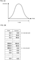
- the electronic cam profile used by the synchronization control unit 11 to control the slave axis includes information about the relationship between the phase of the master axis and the deviation of the slave axis shown in FIG. 2A .
- the phase of the master axis refers to a change in the position of the master axis either from its position at cam synchronization or from the reference position of the master axis.
- the deviation of the slave axis refers to a change in the position of the slave axis either from the position of the master axis at cam synchronization or from the reference position of the slave axis.
- the information in the table shown in FIG. 2B can be used as the electronic cam profile.
- the data values (for phase and deviation) between the cam start point and the cam end point in FIG. 2B correspond to one cycle in FIG. 2A .
- the phase at the cam end point defined by the electronic cam profile is hereafter referred to as an end point phase, and the deviation at the same end point as an end point deviation.
- the end point phase is the phase of data at the cam end point
- the end point deviation is the deviation of data at the cam end point.
- the reference position updater 13 performs a reference position update process every time the master axis reaches the cam end point during the cam control of the master axis and the slave axis performed by the synchronization control unit 11.
- the reference position updater 13 also performs the reference position update process when the controller 10 resumes after a power disconnect in, for example, a power outage or device maintenance.
- the reference position updater 13 performs the reference position update process by obtaining the position of the master axis from the servo system 20, calculating the reference positions of the master axis and the slave axis based on the obtained master axis position, and updating the reference positions of the master axis and the slave axis stored in the reference position storage 12 using the calculation results.
- the reference position updater 13 calculates the reference positions of the master axis and the slave axis using Formulas (1) and (2) below.
- Reference position of master axis Floor current position of master axis ⁇ position of master axis at cam synchronization / end point phase ⁇ end point phase + position of master axis at cam synchronization
- Reference position of slave axis Floor current position of master axis ⁇ position of master axis at cam synchronization / end point phase ⁇ end point deviation + deviation of slave axis at cam synchronization
- the current position of the master axis in Formulas (1) and (2) is the position of the master axis obtained from the servo system 20.
- the floor refers to a floor function.
- the reference position of the master axis is calculated to be 300 and the reference position of the slave axis to be 150 by the calculations shown in the figure in the reference position update process.
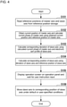
- the return control unit 14 ( FIG. 1 ) performs a return control process shown in FIG. 4 .
- the return control unit 14 performs the process after the controller 10 resumes and the reference position updater 13 completes the reference position update process after the power disconnect in, for example, a power outage or device maintenance.
- the return control unit 14 Upon completion of the reference position update process by the reference position updater 13 after the power disconnect, the return control unit 14 starts the return control process by first reading the reference positions of the master axis and the slave axis from the reference position storage 12 (step S101). Subsequently, the return control unit 14 obtains the current position of the master axis from the servo system 20, and calculates the current phase of the master axis by subtracting the reference position of the master axis from the obtained current position of the master axis (step S102).
- the return control unit 14 calculates, using the calculated current phase of the master axis and the electronic cam profile of the slave axis, the corresponding deviation of the slave axis, which is the deviation of the slave axis corresponding to the current position of the master axis (step S103).
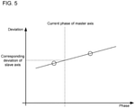
- the return control unit 14 calculates the corresponding deviation of the slave axis, which is the deviation corresponding to the current phase of the master axis, using linear interpolation between the two deviation points at the two phases nearest the current phase of the master axis in the electronic cam profile in step S102, as in the example schematically shown in FIG. 5 .
- step S103 the return control unit 14 causes an operation screen to appear on the display of the operation panel 18 (step S103).
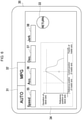
- FIG. 6 is a diagram of an operation screen 30 appearing on the display of the operation panel 18 in step S103.
- the operation screen 30 includes an AUTO button 31, an MPG button 32, a RETURN button 33, a graph area 34, and parameter input fields 35 to 38.
- the graph area 34 includes a graph showing the relationship between the positions of the master axis and the slave axis (white circle) and the electronic cam profile (curve).
- the AUTO button 31 is to be pressed by a user for operation without specifying parameters, such as speed, used in controlling the position of the slave axis.
- the RETURN button 33 is to be pressed by the user for operation specifying parameters, such as speed, used in controlling the position of the slave axis. This button is to be pressed in response to intended values being entered in the parameter input fields 35 to 38.
- the MPG button 32 is to be pressed by the user for manually controlling the position of the slave axis.
- the return control unit 14 that has caused the operation screen 30 to appear on the display of the operation panel 18 waits for an instruction input by the user (step S103).
- the return control unit 14 moves the slave axis to the corresponding position of the slave axis under the default conditions or the conditions specified by the user (step S104), and ends the return control process.
- the return control unit 14 also changes the position of the white circle indicating the positions of the master axis and the slave axis in the graph on the operation screen 30 as the control proceeds.
- the return control unit 14 In response to the MPG button 32 being pressed by the user, the return control unit 14 displays a control screen for manually controlling the position of the slave axis on the operation screen 30 in step S104. The return control unit 14 then controls the slave axis in accordance with the operation received on the control screen, and ends the return control process.
- the axes in response to a power disconnect in, for example, a power outage or device maintenance, can be at reference positions different from the reference positions before the power disconnect.
- a known controller thus involves a manual operation of moving the slave axis to return to the position corresponding to the master axis after the power disconnect.
- the controller 10 according to one or more embodiments recalculates the reference positions of the axes once power is restored after the power disconnect.
- the controller 10 causes the slave axis to automatically return to the position corresponding to the master axis without any inconvenience after the power disconnect. Modifications
- the controller 10 described above may be modified variously.
- the reference position updater 13 may perform the reference position update process at least once every cycle of control defined by the electronic cam profile.
- the reference position updater 13 may perform the reference position update process at a time different from the time described above (when the master axis reaches the cam end point).
- the reference position updater 13 may use any formulas other than Formula (1) or (2) described above to calculate the reference positions of these axes in the reference position update process.
- the graph on the operation screen 30 may show the position of the master axis and the position of the slave axis separately from each other.
- the MPG button 32, the RETURN button 33, and the parameter input fields 35 to 38 may be eliminated from the operation screen 30. Further, the controller 10 may be modified to move the slave axis to the position corresponding to the master axis without waiting for an instruction input by the user.
Landscapes
- Engineering & Computer Science (AREA)
- Human Computer Interaction (AREA)
- Manufacturing & Machinery (AREA)
- Physics & Mathematics (AREA)
- General Physics & Mathematics (AREA)
- Automation & Control Theory (AREA)
- Control Of Position Or Direction (AREA)
- Numerical Control (AREA)
Abstract
Description
- The present invention relates to a controller for performing electronic cam control.
- Motion control for controlling the motions of motors used in machines and equipment may be performed using electronic cams. An electronic cam achieves the operation of a mechanical cam through electronic control and performs synchronization control for synchronizing a master axis and a slave axis to follow an electronic cam profile defined using software.
- At an emergency stop of such an electronic cam system that performs synchronization control (hereafter, electronic cam control), a slave axis may stop at a position deviating from its intended position (hereafter, a position corresponding to the master axis) defined by a stop position of the master axis and the electronic cam profile. When resuming the electronic cam control with the slave axis deviating from the position corresponding to the master axis, the electronic cam system cannot operate each axis as intended. Techniques have been developed for calculating the position corresponding to the master axis using the position of the master axis after an emergency stop and for moving the slave axis to the calculated position corresponding to the master axis without moving the master axis (e.g., Patent Literature 1).
- Patent Literature 1:
Japanese Patent No. 5506456 - The slave axis can stop at the position deviating from the position corresponding to the master axis when the power to the controller is disconnected in, for example, a power outage or device maintenance. A known controller involves a manual operation of a worker to move the slave axis to the position corresponding to the master axis after the power disconnect.
- One or more aspects of the present invention are directed to a controller that causes a slave axis to automatically return to a position corresponding to a master axis after a power disconnect.
- In response to the above issue, a controller according to one aspect of the present invention is a controller for performing synchronization control over a master axis and a slave axis to follow an electronic cam profile. The controller includes a reference position calculator and a return control unit. The reference position calculator, in response to power being restored after a power disconnect, obtains a position of the master axis and calculates a reference position of the master axis and a reference position of the slave axis based on the obtained position of the master axis, a position of the master axis at cam synchronization, and the electronic cam profile. The return control unit performs return control to determine a position of the slave axis corresponding to a current position of the master axis based on the current position of the master axis, the electronic cam profile, and the reference position of the master axis and the reference position of the slave axis calculated by the reference position calculator, and moves the slave axis to the determined position.
- More specifically, a power disconnect in, for example, a power outage or device maintenance can cause the axes to be at reference positions different from the reference positions before the power disconnect. A known controller thus involves a manual operation of moving the slave axis to return to the position corresponding to the master axis after the power disconnect. The controller according to one or more aspects of the present invention recalculates the reference positions of the axes once power is restored. Thus, the controller causes the slave axis to automatically return to the position corresponding to the master axis after the power disconnect in, for example, a power outage or device maintenance.
- The controller may further include an information provider that causes a state screen to appear on a display before the control is performed by the return control unit. The state screen may include a graph showing a relationship between the positions of the master axis and the slave axis and the electronic cam profile. The information provider may change the position of the slave axis shown in the graph in the return control in response to the return control being performed by the return control unit. The controller including the information provider allows a user to easily determine the situation. This controller increases user convenience.
- The controller including the information provider may include the return control unit that starts the return control in response to a predetermined button on the state screen being operated.
- The controller according to the aspects of the present invention causes the slave axis to automatically return to the position corresponding to the master axis after a power disconnect in, for example, a power outage.
-
-
FIG. 1 is a diagram describing the configuration and implementation of a controller according to one embodiment of the present invention. -
FIG. 2A is a graph showing an electronic cam profile. -
FIG. 2B is a table showing the electronic cam profile. -
FIG. 3 is a graph used in a reference position update process for calculating the reference positions of a master axis and a slave axis. -
FIG. 4 is a flowchart of a return control process performed by a return control unit included in the controller. -
FIG. 5 is a graph describing an example procedure for calculating the corresponding deviation of the slave axis. -
FIG. 6 is a diagram of an operation screen to appear on a display panel as controlled by the controller. -
FIG. 1 is a diagram describing the configuration and implementation of acontroller 10 according to one embodiment of the present invention. - The
controller 10 according to the present embodiment is a programmable logic controller (PLC) developed for controlling aservo system 20. Theservo system 20 includes a master axis and multiple slave axes at positions controlled with reference to the position of the master axis. - The
controller 10 may control any number of slave axis. The configuration and the functions of thecontroller 10 controlling theservo system 20 will be described below by way of example. Theservo system 20 includes amotor 22a drivable by aservo driver 21a and amotor 22b drivable by aservo driver 21b as shown inFIG. 1 . The axis of themotor 22a is the master axis, and the axis of themotor 22b is the slave axis. Providing commands to control the position of the master axis (the axis of themotor 22a) and the position of the slave axis (the axis of themotor 22b) to theservo driver - The
controller 10 according to the present embodiment is a PLC connectable to anoperation panel 18 and theservo system 20. Thecontroller 10 is programmed to be operable as asynchronization control unit 11, areference position storage 12, areference position updater 13, areturn control unit 14, and a user interface (Ul) control unit 15. Theoperation panel 18 is a computer including a touchscreen, and functions as an input-output unit for thecontroller 10. - The
reference position storage 12 is a nonvolatile storage for storing the reference positions of the master axis and the slave axis. Thereference position storage 12 also stores the positions of the master axis and the slave axis at the time when the master axis and the slave axis are synchronized with each other through cam control. These axis positions are hereafter referred to as the position of the master axis at cam synchronization and the position of the slave axis at cam synchronization. Thecontroller 10 typically uses part of a rewritable nonvolatile memory such as a flash read-only memory (ROM), or storage such as a hard disk drive (HDD) that are included in thecontroller 10 as thereference position storage 12. - The
synchronization control unit 11 controls the position of the master axis (the rotation angle of the axis of themotor 22a). Thesynchronization control unit 11 also controls the position of the slave axis (the rotation angle of the axis of themotor 22b) to correspond to the position of the master axis to follow a preset electronic cam profile. The electronic cam profile used by thesynchronization control unit 11 to control the slave axis includes information about the relationship between the phase of the master axis and the deviation of the slave axis shown inFIG. 2A . The phase of the master axis refers to a change in the position of the master axis either from its position at cam synchronization or from the reference position of the master axis. The deviation of the slave axis refers to a change in the position of the slave axis either from the position of the master axis at cam synchronization or from the reference position of the slave axis. For example, the information in the table shown inFIG. 2B can be used as the electronic cam profile. The data values (for phase and deviation) between the cam start point and the cam end point inFIG. 2B correspond to one cycle inFIG. 2A . The phase at the cam end point defined by the electronic cam profile is hereafter referred to as an end point phase, and the deviation at the same end point as an end point deviation. In the example inFIG. 2B , the end point phase is the phase of data at the cam end point, and the end point deviation is the deviation of data at the cam end point. - The
reference position updater 13 performs a reference position update process every time the master axis reaches the cam end point during the cam control of the master axis and the slave axis performed by thesynchronization control unit 11. Thereference position updater 13 also performs the reference position update process when thecontroller 10 resumes after a power disconnect in, for example, a power outage or device maintenance. - The
reference position updater 13 performs the reference position update process by obtaining the position of the master axis from theservo system 20, calculating the reference positions of the master axis and the slave axis based on the obtained master axis position, and updating the reference positions of the master axis and the slave axis stored in thereference position storage 12 using the calculation results. Thereference position updater 13 calculates the reference positions of the master axis and the slave axis using Formulas (1) and (2) below.

- The current position of the master axis in Formulas (1) and (2) is the position of the master axis obtained from the
servo system 20. The floor refers to a floor function. - More specifically, as shown in
FIG. 3 , when the position of the master axis at cam synchronization is 100, the position of the slave axis at cam synchronization is 150, the end point phase is 200, the end point deviation is 0, and the obtained current position of the master axis is 450, the reference position of the master axis is calculated to be 300 and the reference position of the slave axis to be 150 by the calculations shown in the figure in the reference position update process. - The return control unit 14 (
FIG. 1 ) performs a return control process shown inFIG. 4 . Thereturn control unit 14 performs the process after thecontroller 10 resumes and thereference position updater 13 completes the reference position update process after the power disconnect in, for example, a power outage or device maintenance. - Upon completion of the reference position update process by the
reference position updater 13 after the power disconnect, thereturn control unit 14 starts the return control process by first reading the reference positions of the master axis and the slave axis from the reference position storage 12 (step S101). Subsequently, thereturn control unit 14 obtains the current position of the master axis from theservo system 20, and calculates the current phase of the master axis by subtracting the reference position of the master axis from the obtained current position of the master axis (step S102). - The
return control unit 14 then calculates, using the calculated current phase of the master axis and the electronic cam profile of the slave axis, the corresponding deviation of the slave axis, which is the deviation of the slave axis corresponding to the current position of the master axis (step S103). When the electronic cam profile is the information in the table inFIG. 2B , thereturn control unit 14 calculates the corresponding deviation of the slave axis, which is the deviation corresponding to the current phase of the master axis, using linear interpolation between the two deviation points at the two phases nearest the current phase of the master axis in the electronic cam profile in step S102, as in the example schematically shown inFIG. 5 . - After step S103, the
return control unit 14 causes an operation screen to appear on the display of the operation panel 18 (step S103). -
FIG. 6 is a diagram of anoperation screen 30 appearing on the display of theoperation panel 18 in step S103. As illustrated, theoperation screen 30 includes anAUTO button 31, anMPG button 32, aRETURN button 33, agraph area 34, and parameter input fields 35 to 38. - The
graph area 34 includes a graph showing the relationship between the positions of the master axis and the slave axis (white circle) and the electronic cam profile (curve). TheAUTO button 31 is to be pressed by a user for operation without specifying parameters, such as speed, used in controlling the position of the slave axis. TheRETURN button 33 is to be pressed by the user for operation specifying parameters, such as speed, used in controlling the position of the slave axis. This button is to be pressed in response to intended values being entered in the parameter input fields 35 to 38. TheMPG button 32 is to be pressed by the user for manually controlling the position of the slave axis. - The
return control unit 14 that has caused theoperation screen 30 to appear on the display of theoperation panel 18 waits for an instruction input by the user (step S103). - In response to the
AUTO button 31 or theRETURN button 33 being pressed by the user, thereturn control unit 14 moves the slave axis to the corresponding position of the slave axis under the default conditions or the conditions specified by the user (step S104), and ends the return control process. In step S104, thereturn control unit 14 also changes the position of the white circle indicating the positions of the master axis and the slave axis in the graph on theoperation screen 30 as the control proceeds. - In response to the
MPG button 32 being pressed by the user, thereturn control unit 14 displays a control screen for manually controlling the position of the slave axis on theoperation screen 30 in step S104. Thereturn control unit 14 then controls the slave axis in accordance with the operation received on the control screen, and ends the return control process. - More specifically, in response to a power disconnect in, for example, a power outage or device maintenance, the axes can be at reference positions different from the reference positions before the power disconnect. A known controller thus involves a manual operation of moving the slave axis to return to the position corresponding to the master axis after the power disconnect. As described above, the
controller 10 according to one or more embodiments recalculates the reference positions of the axes once power is restored after the power disconnect. Thus, thecontroller 10 causes the slave axis to automatically return to the position corresponding to the master axis without any inconvenience after the power disconnect. Modifications - The
controller 10 described above may be modified variously. For example, thereference position updater 13 may perform the reference position update process at least once every cycle of control defined by the electronic cam profile. Thus, thereference position updater 13 may perform the reference position update process at a time different from the time described above (when the master axis reaches the cam end point). Thereference position updater 13 may use any formulas other than Formula (1) or (2) described above to calculate the reference positions of these axes in the reference position update process. - The graph on the operation screen 30 (
FIG. 5 ) may show the position of the master axis and the position of the slave axis separately from each other. TheMPG button 32, theRETURN button 33, and the parameter input fields 35 to 38 may be eliminated from theoperation screen 30. Further, thecontroller 10 may be modified to move the slave axis to the position corresponding to the master axis without waiting for an instruction input by the user. - A controller (10) for performing synchronization control over a master axis and a slave axis to follow an electronic cam profile, the controller (10) comprising:
- a reference position calculator (13) configured to, in response to power being restored after a power disconnect, obtain a position of the master axis and calculate a reference position of the master axis and a reference position of the slave axis based on the obtained position of the master axis, a position of the master axis at cam synchronization, and the electronic cam profile; and
- a return control unit (14) configured to perform return control to determine a position of the slave axis corresponding to a current position of the master axis based on the current position of the master axis, the electronic cam profile, and the reference position of the master axis and the reference position of the slave axis calculated by the reference position calculator, and to move the slave axis to the determined position.
-
- 10
- controller
- 11
- synchronization control unit
- 12
- reference position storage
- 13
- reference position updater
- 14
- return control unit
- 18
- operation panel
- 20
- servo system
- 21a, 21b
- servo driver
- 22a, 22b
- motor
- 30
- operation screen
- 31
- AUTO button
- 32
- MPG button
- 33
- RETURN button
- 34 to 38
- parameter input field
Claims (4)
- A control device for performing synchronization control over a master axis and a slave axis to follow an electronic cam profile, the control device comprising:a reference position calculator configured to, in response to power being restored after a power disconnect, obtain a position of the master axis and calculate a reference position of the master axis and a reference position of the slave axis based on the obtained position of the master axis, a position of the master axis at cam synchronization, and the electronic cam profile; anda return control unit configured to perform return control to determine a position of the slave axis corresponding to a current position of the master axis based on the current position of the master axis, the electronic cam profile, and the reference position of the master axis and the reference position of the slave axis calculated by the reference position calculator, and to move the slave axis to the determined position.
- The control device according to claim 1, further comprising:
an information provider configured to cause a state screen to appear on a display before the return control is performed by the return control unit, the state screen including a graph showing a relationship between the positions of the master axis and the slave axis and the electronic cam profile. - The control device according to claim 2, wherein
the information provider changes the position of the slave axis shown in the graph in the return control in response to the return control being performed by the return control unit. - The control device according to claim 2 or claim 3, wherein
the return control unit starts the return control in response to a predetermined button on the state screen being operated.
Applications Claiming Priority (2)
| Application Number | Priority Date | Filing Date | Title |
|---|---|---|---|
| JP2019067191A JP6943268B2 (en) | 2019-03-29 | 2019-03-29 | Control device |
| PCT/JP2020/009427 WO2020203016A1 (en) | 2019-03-29 | 2020-03-05 | Control device |
Publications (3)
| Publication Number | Publication Date |
|---|---|
| EP3951548A1 true EP3951548A1 (en) | 2022-02-09 |
| EP3951548A4 EP3951548A4 (en) | 2022-12-07 |
| EP3951548B1 EP3951548B1 (en) | 2025-01-01 |
Family
ID=72668822
Family Applications (1)
| Application Number | Title | Priority Date | Filing Date |
|---|---|---|---|
| EP20782171.1A Active EP3951548B1 (en) | 2019-03-29 | 2020-03-05 | Control device |
Country Status (5)
| Country | Link |
|---|---|
| US (1) | US11899430B2 (en) |
| EP (1) | EP3951548B1 (en) |
| JP (1) | JP6943268B2 (en) |
| CN (1) | CN113646723B (en) |
| WO (1) | WO2020203016A1 (en) |
Families Citing this family (1)
| Publication number | Priority date | Publication date | Assignee | Title |
|---|---|---|---|---|
| CN116088413B (en) * | 2023-02-22 | 2026-03-03 | 深圳市雷赛控制技术有限公司 | Control method and device of electronic cam, storage medium and electronic equipment |
Family Cites Families (22)
| Publication number | Priority date | Publication date | Assignee | Title |
|---|---|---|---|---|
| JPS556456B2 (en) | 1972-12-25 | 1980-02-16 | ||
| US4000449A (en) | 1974-10-22 | 1976-12-28 | Westinghouse Electric Corporation | Electrical shaft system |
| US4084083A (en) * | 1975-11-05 | 1978-04-11 | Contraves Goerz Corporation | Multi-axis electronic motion generator |
| JPH0822313A (en) * | 1994-07-08 | 1996-01-23 | Fanuc Ltd | Numerical control unit |
| DE19934044A1 (en) * | 1999-07-16 | 2001-01-25 | Mannesmann Ag | Working clock-synchronous servo axle group coupling/decoupling involves defining axle group demand value with master position value sequence table, servo axle group demand values |
| EP1383018B1 (en) | 2001-04-27 | 2009-06-03 | Citizen Holdings Co., Ltd. | Automatic lathe, and method for controlling the same and device for controlling the same |
| ITVI20010149A1 (en) | 2001-07-04 | 2003-01-04 | Adriano Cazzavillan | METHOD TO COORDINATE AND SYNCHRONIZE THE MOVEMENT OF SERVO-ASSISTED AXES |
| JP3665008B2 (en) * | 2001-10-25 | 2005-06-29 | ファナック株式会社 | Synchronization control method and synchronization control apparatus |
| JP2004199433A (en) * | 2002-12-19 | 2004-07-15 | Fanuc Ltd | Synchronous control device |
| JP2004246498A (en) * | 2003-02-12 | 2004-09-02 | Fanuc Ltd | Position control device |
| DE602006002912D1 (en) | 2005-04-13 | 2008-11-13 | Fanuc Ltd | Numerical control |
| JP4233540B2 (en) | 2005-04-13 | 2009-03-04 | ファナック株式会社 | Numerical control device that drives each axis motor using table format data |
| JP2008090513A (en) | 2006-09-29 | 2008-04-17 | Fanuc Ltd | Numerical controller |
| JP5436073B2 (en) * | 2009-07-06 | 2014-03-05 | 三菱電機株式会社 | Positioning control device and positioning control method |
| JP5506456B2 (en) * | 2010-03-03 | 2014-05-28 | 三菱電機株式会社 | Electronic cam control device |
| JP5803337B2 (en) | 2011-06-28 | 2015-11-04 | オムロン株式会社 | Synchronization control device, synchronization control method, synchronization control program, and computer-readable recording medium recording the synchronization control program |
| KR101269987B1 (en) * | 2012-02-16 | 2013-05-31 | 순환엔지니어링 주식회사 | Apparatus and method of controlling stage apparatus comprising multi-axis |
| JP5963797B2 (en) | 2014-04-01 | 2016-08-03 | リンナイ株式会社 | Thermal power control device |
| JP6235457B2 (en) | 2014-12-25 | 2017-11-22 | ファナック株式会社 | Numerical control device that operates with tabular data |
| JP6262706B2 (en) * | 2015-11-25 | 2018-01-17 | ファナック株式会社 | Cam shape data creation device and synchronization control device |
| JP2017102509A (en) * | 2015-11-30 | 2017-06-08 | ファナック株式会社 | Cam data display device |
| JP6441257B2 (en) | 2016-04-28 | 2018-12-19 | ファナック株式会社 | Numerical control apparatus and synchronous tracking control method |
-
2019
- 2019-03-29 JP JP2019067191A patent/JP6943268B2/en active Active
-
2020
- 2020-03-05 US US17/598,499 patent/US11899430B2/en active Active
- 2020-03-05 WO PCT/JP2020/009427 patent/WO2020203016A1/en not_active Ceased
- 2020-03-05 EP EP20782171.1A patent/EP3951548B1/en active Active
- 2020-03-05 CN CN202080025662.8A patent/CN113646723B/en active Active
Also Published As
| Publication number | Publication date |
|---|---|
| US20220171367A1 (en) | 2022-06-02 |
| WO2020203016A1 (en) | 2020-10-08 |
| EP3951548B1 (en) | 2025-01-01 |
| US11899430B2 (en) | 2024-02-13 |
| JP2020166612A (en) | 2020-10-08 |
| JP6943268B2 (en) | 2021-09-29 |
| CN113646723B (en) | 2024-05-14 |
| CN113646723A (en) | 2021-11-12 |
| EP3951548A4 (en) | 2022-12-07 |
Similar Documents
| Publication | Publication Date | Title |
|---|---|---|
| EP2687929B9 (en) | Computation unit, control method and program for a motion controller | |
| JP5123050B2 (en) | System including robot and press machine, system including a plurality of robots, and control device for robot used in such system | |
| US9182756B2 (en) | Display device, display control method, program, and computer readable recording medium | |
| JP6038189B2 (en) | Synchronous control device | |
| CN102804087A (en) | Controller support device, simulation method of control program, support program of controller and computer-readable storage medium storing support program of controller | |
| US10180674B2 (en) | Controller and control system | |
| EP3361635B1 (en) | Control system and pulse output device | |
| JP2013011937A (en) | Synchronous control device, synchronous control method, synchronous control program, and computer readable recording medium on which synchronous control program is recorded | |
| JP2015176340A (en) | Programmable controller and device control method by programmable controller | |
| US11899430B2 (en) | Control device | |
| CN112470396B (en) | Setting supported devices | |
| JP6262706B2 (en) | Cam shape data creation device and synchronization control device | |
| US20240198531A1 (en) | System and control device | |
| CN110968036A (en) | Numerical controller | |
| CN102981481B (en) | The automatic module control method of apparatus for production line | |
| CN110968045A (en) | Speed control method and device for moving target and readable storage medium | |
| JP6611227B2 (en) | NC machine control system | |
| CN106662855A (en) | Method for setting synchronous control of positioning control device, program, and control setting device for positioning control device | |
| US11121660B2 (en) | System and method for improving drive efficiency in an industrial automation system | |
| US10571885B2 (en) | Method for controlling motor driving by PLC | |
| CN112425065B (en) | Setting supported devices | |
| CN108656115A (en) | A kind of control method and device of the joint speed reducer of prosthetic robot | |
| CN110570938A (en) | graphical scanning progress display method and system | |
| US20190187669A1 (en) | Control unit, data refresh method, and data refresh program | |
| JP6127701B2 (en) | Control device support device and control device support method |
Legal Events
| Date | Code | Title | Description |
|---|---|---|---|
| STAA | Information on the status of an ep patent application or granted ep patent |
Free format text: STATUS: THE INTERNATIONAL PUBLICATION HAS BEEN MADE |
|
| PUAI | Public reference made under article 153(3) epc to a published international application that has entered the european phase |
Free format text: ORIGINAL CODE: 0009012 |
|
| STAA | Information on the status of an ep patent application or granted ep patent |
Free format text: STATUS: REQUEST FOR EXAMINATION WAS MADE |
|
| 17P | Request for examination filed |
Effective date: 20211001 |
|
| AK | Designated contracting states |
Kind code of ref document: A1 Designated state(s): AL AT BE BG CH CY CZ DE DK EE ES FI FR GB GR HR HU IE IS IT LI LT LU LV MC MK MT NL NO PL PT RO RS SE SI SK SM TR |
|
| DAV | Request for validation of the european patent (deleted) | ||
| DAX | Request for extension of the european patent (deleted) | ||
| A4 | Supplementary search report drawn up and despatched |
Effective date: 20221107 |
|
| RIC1 | Information provided on ipc code assigned before grant |
Ipc: G05B 19/4067 20060101AFI20221031BHEP |
|
| REG | Reference to a national code |
Ref country code: DE Ref legal event code: R079 Free format text: PREVIOUS MAIN CLASS: G05D0003000000 Ipc: G05B0019406700 Ref document number: 602020044099 Country of ref document: DE |
|
| GRAP | Despatch of communication of intention to grant a patent |
Free format text: ORIGINAL CODE: EPIDOSNIGR1 |
|
| STAA | Information on the status of an ep patent application or granted ep patent |
Free format text: STATUS: GRANT OF PATENT IS INTENDED |
|
| RIC1 | Information provided on ipc code assigned before grant |
Ipc: G05B 19/4067 20060101AFI20240725BHEP |
|
| INTG | Intention to grant announced |
Effective date: 20240807 |
|
| GRAS | Grant fee paid |
Free format text: ORIGINAL CODE: EPIDOSNIGR3 |
|
| GRAA | (expected) grant |
Free format text: ORIGINAL CODE: 0009210 |
|
| STAA | Information on the status of an ep patent application or granted ep patent |
Free format text: STATUS: THE PATENT HAS BEEN GRANTED |
|
| AK | Designated contracting states |
Kind code of ref document: B1 Designated state(s): AL AT BE BG CH CY CZ DE DK EE ES FI FR GB GR HR HU IE IS IT LI LT LU LV MC MK MT NL NO PL PT RO RS SE SI SK SM TR |
|
| REG | Reference to a national code |
Ref country code: GB Ref legal event code: FG4D |
|
| REG | Reference to a national code |
Ref country code: CH Ref legal event code: EP |
|
| REG | Reference to a national code |
Ref country code: DE Ref legal event code: R096 Ref document number: 602020044099 Country of ref document: DE |
|
| REG | Reference to a national code |
Ref country code: IE Ref legal event code: FG4D |
|
| PGFP | Annual fee paid to national office [announced via postgrant information from national office to epo] |
Ref country code: DE Payment date: 20250331 Year of fee payment: 6 |
|
| REG | Reference to a national code |
Ref country code: LT Ref legal event code: MG9D |
|
| REG | Reference to a national code |
Ref country code: NL Ref legal event code: MP Effective date: 20250101 |
|
| REG | Reference to a national code |
Ref country code: AT Ref legal event code: MK05 Ref document number: 1756885 Country of ref document: AT Kind code of ref document: T Effective date: 20250101 |
|
| PG25 | Lapsed in a contracting state [announced via postgrant information from national office to epo] |
Ref country code: NL Free format text: LAPSE BECAUSE OF FAILURE TO SUBMIT A TRANSLATION OF THE DESCRIPTION OR TO PAY THE FEE WITHIN THE PRESCRIBED TIME-LIMIT Effective date: 20250101 |
|
| PG25 | Lapsed in a contracting state [announced via postgrant information from national office to epo] |
Ref country code: FI Free format text: LAPSE BECAUSE OF FAILURE TO SUBMIT A TRANSLATION OF THE DESCRIPTION OR TO PAY THE FEE WITHIN THE PRESCRIBED TIME-LIMIT Effective date: 20250101 |
|
| PG25 | Lapsed in a contracting state [announced via postgrant information from national office to epo] |
Ref country code: PL Free format text: LAPSE BECAUSE OF FAILURE TO SUBMIT A TRANSLATION OF THE DESCRIPTION OR TO PAY THE FEE WITHIN THE PRESCRIBED TIME-LIMIT Effective date: 20250101 |
|
| PG25 | Lapsed in a contracting state [announced via postgrant information from national office to epo] |
Ref country code: ES Free format text: LAPSE BECAUSE OF FAILURE TO SUBMIT A TRANSLATION OF THE DESCRIPTION OR TO PAY THE FEE WITHIN THE PRESCRIBED TIME-LIMIT Effective date: 20250101 |
|
| PG25 | Lapsed in a contracting state [announced via postgrant information from national office to epo] |
Ref country code: NO Free format text: LAPSE BECAUSE OF FAILURE TO SUBMIT A TRANSLATION OF THE DESCRIPTION OR TO PAY THE FEE WITHIN THE PRESCRIBED TIME-LIMIT Effective date: 20250401 Ref country code: IS Free format text: LAPSE BECAUSE OF FAILURE TO SUBMIT A TRANSLATION OF THE DESCRIPTION OR TO PAY THE FEE WITHIN THE PRESCRIBED TIME-LIMIT Effective date: 20250501 |
|
| PG25 | Lapsed in a contracting state [announced via postgrant information from national office to epo] |
Ref country code: HR Free format text: LAPSE BECAUSE OF FAILURE TO SUBMIT A TRANSLATION OF THE DESCRIPTION OR TO PAY THE FEE WITHIN THE PRESCRIBED TIME-LIMIT Effective date: 20250101 |
|
| PG25 | Lapsed in a contracting state [announced via postgrant information from national office to epo] |
Ref country code: PT Free format text: LAPSE BECAUSE OF FAILURE TO SUBMIT A TRANSLATION OF THE DESCRIPTION OR TO PAY THE FEE WITHIN THE PRESCRIBED TIME-LIMIT Effective date: 20250502 Ref country code: LV Free format text: LAPSE BECAUSE OF FAILURE TO SUBMIT A TRANSLATION OF THE DESCRIPTION OR TO PAY THE FEE WITHIN THE PRESCRIBED TIME-LIMIT Effective date: 20250101 |
|
| PG25 | Lapsed in a contracting state [announced via postgrant information from national office to epo] |
Ref country code: GR Free format text: LAPSE BECAUSE OF FAILURE TO SUBMIT A TRANSLATION OF THE DESCRIPTION OR TO PAY THE FEE WITHIN THE PRESCRIBED TIME-LIMIT Effective date: 20250402 Ref country code: BG Free format text: LAPSE BECAUSE OF FAILURE TO SUBMIT A TRANSLATION OF THE DESCRIPTION OR TO PAY THE FEE WITHIN THE PRESCRIBED TIME-LIMIT Effective date: 20250101 |
|
| PG25 | Lapsed in a contracting state [announced via postgrant information from national office to epo] |
Ref country code: AT Free format text: LAPSE BECAUSE OF FAILURE TO SUBMIT A TRANSLATION OF THE DESCRIPTION OR TO PAY THE FEE WITHIN THE PRESCRIBED TIME-LIMIT Effective date: 20250101 |
|
| PG25 | Lapsed in a contracting state [announced via postgrant information from national office to epo] |
Ref country code: CZ Free format text: LAPSE BECAUSE OF FAILURE TO SUBMIT A TRANSLATION OF THE DESCRIPTION OR TO PAY THE FEE WITHIN THE PRESCRIBED TIME-LIMIT Effective date: 20250101 |
|
| PG25 | Lapsed in a contracting state [announced via postgrant information from national office to epo] |
Ref country code: SE Free format text: LAPSE BECAUSE OF FAILURE TO SUBMIT A TRANSLATION OF THE DESCRIPTION OR TO PAY THE FEE WITHIN THE PRESCRIBED TIME-LIMIT Effective date: 20250101 |
|
| REG | Reference to a national code |
Ref country code: DE Ref legal event code: R097 Ref document number: 602020044099 Country of ref document: DE |
|
| PG25 | Lapsed in a contracting state [announced via postgrant information from national office to epo] |
Ref country code: SM Free format text: LAPSE BECAUSE OF FAILURE TO SUBMIT A TRANSLATION OF THE DESCRIPTION OR TO PAY THE FEE WITHIN THE PRESCRIBED TIME-LIMIT Effective date: 20250101 |
|
| PG25 | Lapsed in a contracting state [announced via postgrant information from national office to epo] |
Ref country code: DK Free format text: LAPSE BECAUSE OF FAILURE TO SUBMIT A TRANSLATION OF THE DESCRIPTION OR TO PAY THE FEE WITHIN THE PRESCRIBED TIME-LIMIT Effective date: 20250101 |
|
| PG25 | Lapsed in a contracting state [announced via postgrant information from national office to epo] |
Ref country code: MC Free format text: LAPSE BECAUSE OF FAILURE TO SUBMIT A TRANSLATION OF THE DESCRIPTION OR TO PAY THE FEE WITHIN THE PRESCRIBED TIME-LIMIT Effective date: 20250101 |
|
| PG25 | Lapsed in a contracting state [announced via postgrant information from national office to epo] |
Ref country code: IT Free format text: LAPSE BECAUSE OF FAILURE TO SUBMIT A TRANSLATION OF THE DESCRIPTION OR TO PAY THE FEE WITHIN THE PRESCRIBED TIME-LIMIT Effective date: 20250101 |
|
| PG25 | Lapsed in a contracting state [announced via postgrant information from national office to epo] |
Ref country code: EE Free format text: LAPSE BECAUSE OF FAILURE TO SUBMIT A TRANSLATION OF THE DESCRIPTION OR TO PAY THE FEE WITHIN THE PRESCRIBED TIME-LIMIT Effective date: 20250101 |
|
| REG | Reference to a national code |
Ref country code: CH Ref legal event code: H13 Free format text: ST27 STATUS EVENT CODE: U-0-0-H10-H13 (AS PROVIDED BY THE NATIONAL OFFICE) Effective date: 20251023 |
|
| PG25 | Lapsed in a contracting state [announced via postgrant information from national office to epo] |
Ref country code: RO Free format text: LAPSE BECAUSE OF FAILURE TO SUBMIT A TRANSLATION OF THE DESCRIPTION OR TO PAY THE FEE WITHIN THE PRESCRIBED TIME-LIMIT Effective date: 20250101 |
|
| PG25 | Lapsed in a contracting state [announced via postgrant information from national office to epo] |
Ref country code: SK Free format text: LAPSE BECAUSE OF FAILURE TO SUBMIT A TRANSLATION OF THE DESCRIPTION OR TO PAY THE FEE WITHIN THE PRESCRIBED TIME-LIMIT Effective date: 20250101 |
|
| PLBE | No opposition filed within time limit |
Free format text: ORIGINAL CODE: 0009261 |
|
| STAA | Information on the status of an ep patent application or granted ep patent |
Free format text: STATUS: NO OPPOSITION FILED WITHIN TIME LIMIT |
|
| PG25 | Lapsed in a contracting state [announced via postgrant information from national office to epo] |
Ref country code: LU Free format text: LAPSE BECAUSE OF NON-PAYMENT OF DUE FEES Effective date: 20250305 |
|
| 26N | No opposition filed |
Effective date: 20251002 |
|
| REG | Reference to a national code |
Ref country code: BE Ref legal event code: MM Effective date: 20250331 |
|
| GBPC | Gb: european patent ceased through non-payment of renewal fee |
Effective date: 20250401 |
|
| PG25 | Lapsed in a contracting state [announced via postgrant information from national office to epo] |
Ref country code: GB Free format text: LAPSE BECAUSE OF NON-PAYMENT OF DUE FEES Effective date: 20250401 |
|
| PG25 | Lapsed in a contracting state [announced via postgrant information from national office to epo] |
Ref country code: FR Free format text: LAPSE BECAUSE OF NON-PAYMENT OF DUE FEES Effective date: 20250331 |
|
| PG25 | Lapsed in a contracting state [announced via postgrant information from national office to epo] |
Ref country code: BE Free format text: LAPSE BECAUSE OF NON-PAYMENT OF DUE FEES Effective date: 20250331 |
|
| PG25 | Lapsed in a contracting state [announced via postgrant information from national office to epo] |
Ref country code: CH Free format text: LAPSE BECAUSE OF NON-PAYMENT OF DUE FEES Effective date: 20250331 |
|
| PG25 | Lapsed in a contracting state [announced via postgrant information from national office to epo] |
Ref country code: IE Free format text: LAPSE BECAUSE OF NON-PAYMENT OF DUE FEES Effective date: 20250305 |
|
| PG25 | Lapsed in a contracting state [announced via postgrant information from national office to epo] |
Ref country code: CY Free format text: LAPSE BECAUSE OF FAILURE TO SUBMIT A TRANSLATION OF THE DESCRIPTION OR TO PAY THE FEE WITHIN THE PRESCRIBED TIME-LIMIT Effective date: 20250101 |
|
| PG25 | Lapsed in a contracting state [announced via postgrant information from national office to epo] |
Ref country code: RS Free format text: LAPSE BECAUSE OF FAILURE TO SUBMIT A TRANSLATION OF THE DESCRIPTION OR TO PAY THE FEE WITHIN THE PRESCRIBED TIME-LIMIT Effective date: 20250101 |
|
| PG25 | Lapsed in a contracting state [announced via postgrant information from national office to epo] |
Ref country code: LT Free format text: LAPSE BECAUSE OF FAILURE TO SUBMIT A TRANSLATION OF THE DESCRIPTION OR TO PAY THE FEE WITHIN THE PRESCRIBED TIME-LIMIT Effective date: 20250101 |
|
| PG25 | Lapsed in a contracting state [announced via postgrant information from national office to epo] |
Ref country code: TR Free format text: LAPSE BECAUSE OF FAILURE TO SUBMIT A TRANSLATION OF THE DESCRIPTION OR TO PAY THE FEE WITHIN THE PRESCRIBED TIME-LIMIT Effective date: 20250101 |