EP3951483A1 - Measuring method for measuring sensing capability of eye of subject, and setting method for progressive power lens - Google Patents
Measuring method for measuring sensing capability of eye of subject, and setting method for progressive power lens Download PDFInfo
- Publication number
- EP3951483A1 EP3951483A1 EP20782447.5A EP20782447A EP3951483A1 EP 3951483 A1 EP3951483 A1 EP 3951483A1 EP 20782447 A EP20782447 A EP 20782447A EP 3951483 A1 EP3951483 A1 EP 3951483A1
- Authority
- EP
- European Patent Office
- Prior art keywords
- subject
- change region
- display screen
- intersection point
- fixation target
- Prior art date
- Legal status (The legal status is an assumption and is not a legal conclusion. Google has not performed a legal analysis and makes no representation as to the accuracy of the status listed.)
- Granted
Links
Images


Classifications
-
- A—HUMAN NECESSITIES
- A61—MEDICAL OR VETERINARY SCIENCE; HYGIENE
- A61B—DIAGNOSIS; SURGERY; IDENTIFICATION
- A61B3/00—Apparatus for testing the eyes; Instruments for examining the eyes
- A61B3/02—Subjective types, i.e. testing apparatus requiring the active assistance of the patient
- A61B3/028—Subjective types, i.e. testing apparatus requiring the active assistance of the patient for testing visual acuity; for determination of refraction, e.g. phoropters
-
- A—HUMAN NECESSITIES
- A61—MEDICAL OR VETERINARY SCIENCE; HYGIENE
- A61B—DIAGNOSIS; SURGERY; IDENTIFICATION
- A61B3/00—Apparatus for testing the eyes; Instruments for examining the eyes
- A61B3/0016—Operational features thereof
- A61B3/0041—Operational features thereof characterised by display arrangements
- A61B3/005—Constructional features of the display
-
- A—HUMAN NECESSITIES
- A61—MEDICAL OR VETERINARY SCIENCE; HYGIENE
- A61B—DIAGNOSIS; SURGERY; IDENTIFICATION
- A61B3/00—Apparatus for testing the eyes; Instruments for examining the eyes
- A61B3/0091—Fixation targets for viewing direction
-
- A—HUMAN NECESSITIES
- A61—MEDICAL OR VETERINARY SCIENCE; HYGIENE
- A61B—DIAGNOSIS; SURGERY; IDENTIFICATION
- A61B3/00—Apparatus for testing the eyes; Instruments for examining the eyes
- A61B3/02—Subjective types, i.e. testing apparatus requiring the active assistance of the patient
- A61B3/028—Subjective types, i.e. testing apparatus requiring the active assistance of the patient for testing visual acuity; for determination of refraction, e.g. phoropters
- A61B3/032—Devices for presenting test symbols or characters, e.g. test chart projectors
-
- G—PHYSICS
- G02—OPTICS
- G02C—SPECTACLES; SUNGLASSES OR GOGGLES INSOFAR AS THEY HAVE THE SAME FEATURES AS SPECTACLES; CONTACT LENSES
- G02C7/00—Optical parts
- G02C7/02—Lenses; Lens systems ; Methods of designing lenses
- G02C7/024—Methods of designing ophthalmic lenses
- G02C7/025—Methods of designing ophthalmic lenses considering parameters of the viewed object
-
- G—PHYSICS
- G02—OPTICS
- G02C—SPECTACLES; SUNGLASSES OR GOGGLES INSOFAR AS THEY HAVE THE SAME FEATURES AS SPECTACLES; CONTACT LENSES
- G02C7/00—Optical parts
- G02C7/02—Lenses; Lens systems ; Methods of designing lenses
- G02C7/024—Methods of designing ophthalmic lenses
- G02C7/027—Methods of designing ophthalmic lenses considering wearer's parameters
-
- G—PHYSICS
- G02—OPTICS
- G02C—SPECTACLES; SUNGLASSES OR GOGGLES INSOFAR AS THEY HAVE THE SAME FEATURES AS SPECTACLES; CONTACT LENSES
- G02C7/00—Optical parts
- G02C7/02—Lenses; Lens systems ; Methods of designing lenses
- G02C7/06—Lenses; Lens systems ; Methods of designing lenses bifocal; multifocal ; progressive
- G02C7/061—Spectacle lenses with progressively varying focal power
- G02C7/063—Shape of the progressive surface
- G02C7/066—Shape, location or size of the viewing zones
-
- A—HUMAN NECESSITIES
- A61—MEDICAL OR VETERINARY SCIENCE; HYGIENE
- A61B—DIAGNOSIS; SURGERY; IDENTIFICATION
- A61B3/00—Apparatus for testing the eyes; Instruments for examining the eyes
- A61B3/02—Subjective types, i.e. testing apparatus requiring the active assistance of the patient
- A61B3/024—Subjective types, i.e. testing apparatus requiring the active assistance of the patient for determining the visual field, e.g. perimeter types
Definitions
- the present invention relates to a measuring method for measuring sensitivity of an eye around a certain line of sight that is maintained by a subject and also relates to a designing method for designing a progressive power lens by using measurement result of the measuring method.
- the progressive power lens has regions of a distance vision part for distance viewing, a near vision part for near viewing, and an intermediate vision part positioned between the distance vision part and the near vision part, and the progressive power lens changes in refractive power between the distance vision part and the near vision part.
- the progressive power lens is designed by determining a spherical power at the distance measurement position, a cylindrical power and an addition power, in accordance with the distance power, astigmatism power, and near power of a person who will purchase eyeglasses (hereinafter simply called a "purchaser").
- a progressive power lens is individually designed so as to be suitable for an eye of each purchaser by adjusting a spherical power, a cylindrical power, and an addition power.
- a progressive power lens more suitable for an eye of a purchaser it is preferable to take into consideration sensitivity of an eye around a line of sight that is maintained to be directed to a direction other than forward, in addition to a spherical power, a cylindrical power, and an addition power.
- the sensitivity of an eye around a line of sight differs for each purchaser.
- Patent literature 1 a method for quantitatively measuring a field of view of a subject is publicly known (Patent literature 1).
- This method for measuring a field of view is performed as follows. A face image containing a human face is shown so that a subject will look at it straightly from forward. Then, visual stimuli are generated at multiple positions that have mutually different distances from a target fixation point determined in an area of face in the face image. On the basis of positions where a subject recognized the generated visual stimuli, a field of view of the subject is measured. The visual stimuli are generated in an area of the hair of head and in an area outside the head, including the face and the hair, in the face image.
- Patent literature 1 Japanese Unexamined Patent Application Laid-Open No. 2013-085709
- the above method fails to disclose a technique for measuring sensitivity of an eye around a line of sight that is maintained in a certain direction.
- blurring of an image easily occurs in a side area laterally separated from a main fixation axis, in the intermediate vision part or the near vision part in a progressive power lens.
- Sensitivity to this blurring of an image varies depending on the person. That is, a sensible range in which a blur of an image extends in a side area from the intermediate vision part to the near vision part differs between individuals. For this reason, it is preferable to measure sensitivity of an eye around a certain line of sight that is maintained, in terms of providing a progressive power lens more suitable for a purchaser of an eyeglass lens.
- an object of the present invention is to provide a measuring method for measuring sensitivity of an eye around a certain line of sight that is maintained by a subject and to provide a designing method for designing a progressive power lens by using measurement result of the measuring method.
- An embodiment of the present disclosure is a measuring method for measuring sensitivity of an eye around a certain line of sight that is maintained by a subject.
- the measuring method includes:
- the change region may be at least one continuous region that continuously extends from a side edge of the display screen relative to the intersection point, toward the intersection point or the fixation target.
- the change region may be at least one continuous region that continuously extends from an upper edge or a lower edge of the display screen relative to the intersection point, toward the intersection point or the fixation target.
- the change region may be formed on at least one of right and left sides bounded by a vertical line that is parallel to an up-down direction of the display screen while passing the intersection point, and the change region does not cross the vertical line.
- the fixation target may be a region having predetermined dimensions
- the change region may include a blurred image of the pattern.
- the measuring method may include comprising showing the pattern by changing a degree of blurring of the image of the pattern in the change region in a predetermined range, at the time of showing the change region on the display screen.
- the sensitivity of the eye may include information of a sensible distance of the change region from the intersection point in the condition in which the change region can be sensed by the subject and is most separated from the intersection point.
- the sensible distance may be determined in accordance with the degree of blurring, and the sensitivity of the eye includes information of a set of the degree of blurring and the sensible distance corresponding to the degree of blurring.
- the certain line of sight may be in a direction different from a direction of a line of sight of the subject looking forward straightly.
- the certain line of sight may be directed downward relative to the line of sight of the subject looking forward straightly.
- the image of the pattern shown on the display screen, in a region other than the change region may have a constant degree of the change irrespective of the position in the display screen.
- An embodiment of the present disclosure is a designing method for a progressive power lens suitable for an eye of a subject, the progressive power lens having regions of a distance vision part for distance viewing, a near vision part for near viewing, and an intermediate vision part positioned between the distance vision part and the near vision part, the progressive power lens changing in refractive power between the distance vision part and the near vision part.
- the designing method includes:
- the measuring method enables measuring sensitivity of an eye around a certain line of sight that is maintained by a subject. As a result, it is possible to design a progressive power lens suitable for sensitivity of an eye that differs depending on the purchaser of an eyeglass lens.
- FIG. 1 shows a schematic configuration of a measurement system 1 that implements a measuring method for measuring sensitivity of an eye of a subject according to an embodiment.
- the sensitivity of an eye is an ability of an eye relating to whether a subject can recognize change of an image of a pattern shown around a certain line of sight, while focusing on a certain part of the pattern and maintaining the certain line of sight.
- the image of the pattern is predetermined and is shown on a display screen.
- This sensitivity is different from sensibility of a subject that is examined in terms of a degree of endurance with psychological pain.
- the psychological pain is caused by change of a pattern, for example, a blurred pattern, in a state in which the change of the pattern is recognized.
- the measurement system 1 primarily includes a computer 10 and a head-mounted display 16.
- the head-mounted display 16 is a display device that shows a display screen in front of an eyeball of a subject "S", in a state of being secured to the head of the subject "S".
- FIG. 1 shows an example of using the head-mounted display 16 as a display device, but any display device can be used on the condition that it shows a display screen in front of an eyeball of the subject "S” in a state of being secured to the head of the subject "S".
- the computer 10 is connected to an input operation system 12 including a mouse, a keyboard, an input mechanism that allows input by operating a button, or the like, and the computer 10 is also connected to a monitor 14.
- the monitor 14 displays information such as a result of measuring sensitivity of an eyeball, and a pattern and a change region of the pattern that are shown on the display screen of the head-mounted display 16 during measurement, which will be described later.
- a measurement condition setting screen is also displayed to allow setting details of a procedure of the measuring method for measuring sensitivity of an eyeball.
- the computer 10 includes a memory, which is not shown in the drawing, and measurement software for measuring sensitivity of an eye is recorded in the memory.
- the computer 10 reads and drives this measurement software and thereby makes the head-mounted display 16 show display information on the display screen, as described below.
- the head-mounted display 16 shows an image of a predetermined pattern on the display screen in accordance with an instruction from the computer 10. Moreover, in order to make a line of sight of a subject "S" be a certain line of sight, a fixation target to be focused on by the subject "S” is shown on the display screen.
- the pattern is preferably a series of unit element shapes that are continuous vertically and laterally. Examples of the pattern include a lattice pattern and a checkered pattern in which black and white rectangular regions are arranged alternately with each other.
- the fixation target occupies a certain area defined by, for example, a rectangular frame, a circular frame, or a circle.
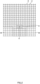
- FIG. 2 shows an example of a pattern "P" that is shown on a display screen 17.
- the pattern "P" is a lattice pattern, and rectangular lattices are arranged on the display screen 17. It is preferable that approximately 10 to 30 lattices be arranged vertically and laterally on the display screen 17, in terms of measuring sensitivity for a change region.
- the rectangular shapes of the arranged lattices are preferably square.
- the subject "S” aims the line of sight at a fixation target "A” in accordance with an instruction.
- the fixation target "A” is a region enclosed by a rectangular frame.
- the head-mounted display 16 shows a change region where the image of the pattern "P" is changed, at an anisotropic area around an intersection point “O” or the fixation target "A” in the display screen 17.
- the anisotropic area is separated from the intersection point “O” and the fixation target "A".
- the intersection point “O” is where a certain line of sight of the subject "S” focusing on the fixation target "A” crosses the display screen 17.
- the intersection point "O" which is a point where a line of sight of the subject "S” focusing on the fixation target "A” crosses the display screen 17, corresponds to an approximately center point in the region of the fixation target "A".
- FIG. 2 shows a change region "M” where an image of lattice lines is blurred.
- the change region "M” may have a deformed shape in which an original shape, such as a rectangular shape of a lattice pattern, is deformed, instead of a blur of an image.
- the change region may be a region where a difference in brightness between the lattice lines and a background area is varied from that in an area other than the change region.
- the anisotropic region means a region other than an isotropic region that is defined by a circular shape centering at the intersection point "O" or the fixation target "A".
- the anisotropic region also includes a disk-shaped area having a circular hole at its center and having a cut part.
- the head-mounted display 16 shows a change region where the image of the displayed pattern is changed, on the display screen 17, in such a manner that the change region is continuously or intermittently brought close to or away from the intersection point "O" or the fixation target "A" in the display screen 17.
- Continuously bringing the change region closer or farther away means bringing the change region closer or farther away at a predetermined rate.
- Intermittently bringing the change region closer or farther away means bringing the change region closer or farther away at a constant time interval.
- a change region having a certain area or a certain shape may be brought close to or away from the intersection point "O" or the fixation target "A".
- a change region which extends from an edge of the display screen 17, may approach in such a manner as to be enlarged toward the intersection point "O” or the fixation target "A", or may be separated in such a manner as to be retracted from the intersection point "O” or the fixation target "A" toward the edge of the display screen 17.
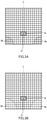
- FIGs. 3A and 3B are explanatory drawings of examples of change regions.
- the change region "M” extends from an edge of the display screen 17 and has a small area.
- the change region "M” extends from an edge of the display screen 17 and has an area larger than that of the change region "M” shown in FIG. 3A , whereby the change region "M” comes close to the intersection point "O" or the fixation target "A".
- the head-mounted display 16 shows the change region "M” in such a manner that the change region “M” is continuously or intermittently brought close to or away from the intersection point "O" or the fixation target "A".
- the computer 10 determines a range in which the subject "S” can sense the change region "M", whereby sensitivity of an eye is measured.
- the subject "S” looking at the display screen 17 presses a button of an input mechanism of the input operation system 12 by hand operation, to notify the computer 10 that the subject "S” has sensed the change region "M”.
- the computer 10 determines the sensible range of the change region on the basis of information of the change region "M” that is shown on the display screen 17 at the time of receiving a signal for notifying that the subject "S” has sensed the change region "M".
- the information of the change region "M” includes a distance of the change region to the intersection point "O” or the fixation target "A”, and a degree of change of the image in the change region "M", for example, a degree of blurring in the case of using a blur.
- the measurement system 1 determines the range that can be sensed by the subject "S", in response to hand operation for pressing the button of the input mechanism of the input operation system 12 by the subject "S", that is, in accordance with self notification from the subject "S”. However, the determination can be performed based on information other than the self notification of the subject "S”. Abiological reaction tends to appear when the change region "M" is sensed.
- the sensible range may be determined based on a change in biological signal by using a measuring device for measuring a biological signal of the subject "S", such as an electroencephalogram, a magnetoencephalogram, or blood flow information.
- the measurement system 1 shows the fixation target "A” on the display screen 17 to make the subject "S” focus on the fixation target "A", and in this state, continuously or intermittently brings the change region "M” close to or away from the intersection point "O” or the fixation target "A” while the line of sight is maintained.
- This enables quantitatively measuring sensitivity of an eye around a predetermined line of sight, with high accuracy.
- the change region "M” is preferably at least one continuous region that continuously extends from a side edge of the display screen 17 relative to the intersection point "O” or the fixation target "A", toward the intersection point “O” or the fixation target "A".
- the change region "M”, which continuously extends from a side edge of the display screen 17, makes it possible to efficiently measure a sensible distance (shortest distance) in a right-left direction from the intersection point "O” or the fixation target "A" to the change region "M".
- the change region "M” is preferably at least one continuous region that continuously extends from an upper edge or a lower edge of the display screen 17 relative to the intersection point "O", toward the intersection point "O" or the fixation target "A".
- the change region "M”, which continuously extends from an upper edge or a lower edge of the display screen 17, makes it possible to efficiently measure a sensible distance (shortest distance) in an up-down direction from the intersection point "O” or the fixation target "A" to the change region "M".
- the change region "M" may be at least one continuous region that continuously extends from an upper edge or a lower edge, and a side edge of the display screen 17 relative to the intersection point "O", toward the intersection point "O" or the fixation target "A".
- a sensible distance (shortest distance) in the up-down direction, the right-left direction, or a direction tilted from the right-left direction, from the intersection point O or the fixation target "A" to the change region "M” can be efficiently measured.
- the change region "M” is preferably formed on at least one of right and left sides bounded by a vertical line that is parallel to the up-down direction of the display screen 17 while passing the intersection point "O", and the change region "M” preferably does not cross the vertical line. As shown in FIGs. 3A and 3B , the change region “M” is formed so as to not cross a vertical line "L". This change region "M” corresponds to a side area of an eyeglass lens. Sensitivity for this change region "M” corresponds to sensitivity for the side area of an eyeglass lens and is thereby effectively used in designing the side area of an eyeglass lens.
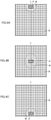
- FIGs. 4A to 4C are explanatory drawings of examples of the change regions used in one embodiment. That is, in the one embodiment shown in FIGs. 4A to 4C , the fixation target "A" is a region having predetermined dimensions, and the change region “M” is provided so as to surround the region of the fixation target "A” and has a largest degree of change of the image of the pattern "P" in the display screen 17.
- an outer region “B” that surrounds the change region “M” is provided in the display screen 17, and the outer region “B” preferably has no change as in the region of the fixation target "A". It is also possible to measure sensitivity around a line of sight by using such a display. Under these conditions, the outer region “B” is not limited to a region having no change as in the region of the fixation target "A", and it may be a region having a small degree of change compared with that of the image in the change region "M”.
- the change region "M" preferably includes a blurred image of the pattern "P".
- Blurring can occur in a side area of an eyeglass lens, in particular, a progressive power lens.
- the head-mounted display 16 preferably shows the pattern "P" by changing the degree of blurring of the image of the pattern "P” in the change region "M” in a predetermined range, at the time of showing the change region "M” on the display screen 17.
- the sensible range in which an eye senses blurring around a line of sight varies depending on the degree of blurring and also on the person.
- the sensitivity of an eye preferably includes information of a sensible distance of the change region "M" from the intersection point “O” in the condition in which the change region "M” can be sensed by the subject "S” and is most separated from the intersection point "O".
- the distance from the intersection point “O” is the shortest distance from the intersection point "O” to the change region "M".
- the information of the sensible distance relates to a distance from a line of sight, of a position where the change region "M" starts to be sensed.
- the information of the sensible distance from the intersection point "O” in the condition in which the intersection point "O” is most separated is preferably used as an index of sensitivity of an eye.
- the sensible distance is determined in accordance with a degree of blurring in the change region "M".
- information containing a set of the degree of blurring and the sensible distance corresponding to the degree of blurring is preferably used as an index of sensitivity of an eye.
- the degree of blurring is lower, the sensible distance tends to be shorter.
- a line of sight that is aimed at the fixation target "A” is preferably in a direction different from that of a line of sight of the subject "S" looking forward straightly.
- This direction includes an up-down direction, a right-left direction, and a direction tilted from the right-left direction.
- a line of sight directed downward relative to a front line of sight corresponds to a line of sight when a person wearing eyeglasses looks at a near position by using near vision parts of progressive power lenses.
- the image of the pattern "P” in a region other than the change region "M” preferably has a constant degree of change irrespective of the position in the display screen 17.
- the degrees of blurring in the region of the fixation target "A" and in the outer region “B” are preferably the same.
- the degree of change in the region other than the change region "M” can be set as desired on the condition that it is constant.
- the region other than the change region "M” preferably has a degree of blurring smaller than that in the change region "M", and more preferably has no blur.
- the change region "M” may be shown on each of right and left sides of a line of sight at the same time, on the display screen 17, as shown in FIGs. 2 , 3A, and 3B . However, the change region “M” may be shown on one side, and sensitivity relating to the change region "M" on a right side or a left side of a line of sight may be measured.
- the measurement system 1 may collectively measure sensitivity of both eyes relating to the change region "M", but may measure it with respect to each eye.
- Sensitivity of both eyes may be collectively measured by separately showing two patterns.
- One of the two patterns has the change region "M" in an area on an inner side (nose side) in the right-left direction of lines of sights of both eyes.
- the other has the change region "M" in an area on an outer side (side opposite to the nose side) in the right-left direction. In this case, sensitivities of both eyes on the outer side and on the inner side in the right-left direction are measured separately.
- Sensitivity of one eye may be measured by separately showing two patterns.
- One of the two patterns has the change region "M” only in the area on the inner side (nose side) in the right-left direction.
- the other has the change region "M” only in the area on the outer side (side opposite to the nose side) in the right-left direction.
- sensitivity of one eye may be measured by showing a pattern having the change region "M" in an area on each side in the right-left direction. In these cases, sensitivities of one eye on the outer side and on the inner side are measured separately, or sensitivities of one eye on both sides in the right-left direction may be collectively measured at the same time.
- FIG. 5 schematically shows a progressive power lens in a state of a circle-shaped lens substrate that is not edged to fit to the shape of an eyeglass frame.
- the progressive power lens is an eyeglass lens that has regions of a distance vision part for distance viewing, a near vision part for near viewing, and an intermediate vision part positioned between the distance vision part and the near vision part, and the progressive power lens changes in refractive power between the distance vision part and the near vision part.
- This measurement provides information of sensitivity for the change region "M”.
- a refractive power distribution in a progressive power lens is designed.
- side areas on right and left sides in the regions from the intermediate vision part to the near vision part often generate astigmatism to cause blurring or distorting of an image, whereby a purchaser tends to have uncomfortable wear feeling (uncomfortable feeling due to blurring or distorting of an image).
- a purchaser as the subject "S”
- measure the sensitivity of an eye measure the sensitivity of an eye
- design a progressive power lens based on the measurement result so as to not give uncomfortable wear feeling.
- a distribution of astigmatism in a clear visual field area or a side area from the intermediate vision part to the near vision part is preferably adjusted in accordance with sensitivity of an eye for the change region "M".
- sensitivity is low for a low degree of blurring, but is high for a high degree of blurring
- a maximum astigmatism amount in the side area is reduced by dispersing regions having low astigmatism amounts, to a wide area.
- the fixation target "A” is shown on the display screen 17 of the display device to make the subject "S” focus on the fixation target "A", and in this state, the change region “M” is continuously or intermittently brought close to or away from the intersection point "O" or the fixation target "A” while the line of sight is maintained.
- the sensitivity is an ability relating to whether the change region can be sensed, and therefore, it is possible to measure the range in which the change region "M” can be sensed, by continuously or intermittently bringing the change region "M” closer or farther away.
- the wear feeling of eyeglasses of a purchaser who will purchase eyeglasses differs depending on this sensitivity. Thus, an eyeglass lens suitable for a purchaser and not giving uncomfortable wear feeling can be provided.
- the measurement of sensitivity of an eye may be performed in the state in which the eyeglasses are worn.
- information of the sensible distance is preferably corrected by using light ray tracking of an eyeglass lens.
- a degree of deformation in the change region "M", which is sensed by the subject "S” is preferably corrected in consideration of the shape of an eyeglass lens.
- the sensitivity is preferably measured by preparing multiple eyeglass lenses having known lens characteristics in advance and using an eyeglass lens most appropriate for the subject "S" among these eyeglass lenses.
- the measuring method for measuring sensitivity of an eye of a subject and a designing method for a progressive power lens of the present invention are detailed above.
- the present invention is not limited to the foregoing embodiments, and of course, various modifications and alterations may be made without departing from the gist of the present invention.
Landscapes
- Health & Medical Sciences (AREA)
- Ophthalmology & Optometry (AREA)
- Physics & Mathematics (AREA)
- Life Sciences & Earth Sciences (AREA)
- General Health & Medical Sciences (AREA)
- General Physics & Mathematics (AREA)
- Optics & Photonics (AREA)
- Engineering & Computer Science (AREA)
- Biophysics (AREA)
- Biomedical Technology (AREA)
- Heart & Thoracic Surgery (AREA)
- Medical Informatics (AREA)
- Molecular Biology (AREA)
- Surgery (AREA)
- Animal Behavior & Ethology (AREA)
- Public Health (AREA)
- Veterinary Medicine (AREA)
- Eye Examination Apparatus (AREA)
- Eyeglasses (AREA)
Abstract
Description
- The present invention relates to a measuring method for measuring sensitivity of an eye around a certain line of sight that is maintained by a subject and also relates to a designing method for designing a progressive power lens by using measurement result of the measuring method.
- Eyeglass lenses using progressive power lenses are publicly known. The progressive power lens has regions of a distance vision part for distance viewing, a near vision part for near viewing, and an intermediate vision part positioned between the distance vision part and the near vision part, and the progressive power lens changes in refractive power between the distance vision part and the near vision part.
- The progressive power lens is designed by determining a spherical power at the distance measurement position, a cylindrical power and an addition power, in accordance with the distance power, astigmatism power, and near power of a person who will purchase eyeglasses (hereinafter simply called a "purchaser").
- A progressive power lens is individually designed so as to be suitable for an eye of each purchaser by adjusting a spherical power, a cylindrical power, and an addition power. For a progressive power lens more suitable for an eye of a purchaser, it is preferable to take into consideration sensitivity of an eye around a line of sight that is maintained to be directed to a direction other than forward, in addition to a spherical power, a cylindrical power, and an addition power. The sensitivity of an eye around a line of sight differs for each purchaser.
- For example, a method for quantitatively measuring a field of view of a subject is publicly known (Patent literature 1).
- This method for measuring a field of view is performed as follows. A face image containing a human face is shown so that a subject will look at it straightly from forward. Then, visual stimuli are generated at multiple positions that have mutually different distances from a target fixation point determined in an area of face in the face image. On the basis of positions where a subject recognized the generated visual stimuli, a field of view of the subject is measured. The visual stimuli are generated in an area of the hair of head and in an area outside the head, including the face and the hair, in the face image.
- Patent literature 1:
Japanese Unexamined Patent Application Laid-Open No. 2013-085709 - In the above method, a field of view of a subject is measured only in the state in which the subject looks forward straightly. Thus, the above method fails to disclose a technique for measuring sensitivity of an eye around a line of sight that is maintained in a certain direction.
- In particular, blurring of an image easily occurs in a side area laterally separated from a main fixation axis, in the intermediate vision part or the near vision part in a progressive power lens. Sensitivity to this blurring of an image varies depending on the person. That is, a sensible range in which a blur of an image extends in a side area from the intermediate vision part to the near vision part differs between individuals. For this reason, it is preferable to measure sensitivity of an eye around a certain line of sight that is maintained, in terms of providing a progressive power lens more suitable for a purchaser of an eyeglass lens.
- In view of this, an object of the present invention is to provide a measuring method for measuring sensitivity of an eye around a certain line of sight that is maintained by a subject and to provide a designing method for designing a progressive power lens by using measurement result of the measuring method.
- An embodiment of the present disclosure is a measuring method for measuring sensitivity of an eye around a certain line of sight that is maintained by a subject. The measuring method includes:
- showing an image of a predetermined pattern on a display screen, the display screen being shown in front of an eyeball of the subject by a display device that is secured to a head of the subject;
- showing a fixation target to be focused on by the subject, on the described screen, in order to make a line of sight of the subject be the certain line of sight;
- showing a change region where the image of the predetermined pattern is changed, at an anisotropic area around an intersection point or the fixation target in the display screen, the anisotropic area being separated from the intersection point and the fixation target, the intersection point being where the certain line of sight of the subject focusing on the fixation target, crosses the display screen;
- showing the change region where the image of the predetermined pattern is changed, on the display screen, in such a manner that the change region is continuously or intermittently brought close to or away from the intersection point or the fixation target in the display screen; and
- determining a range in which the subject can sense the change region, in response to the change region shown by bringing the change region close to or away from the intersection point or the fixation target, whereby the sensitivity of the eye is measured.
- Preferably, the change region may be at least one continuous region that continuously extends from a side edge of the display screen relative to the intersection point, toward the intersection point or the fixation target.
- Preferably, the change region may be at least one continuous region that continuously extends from an upper edge or a lower edge of the display screen relative to the intersection point, toward the intersection point or the fixation target.
- Preferably, the change region may be formed on at least one of right and left sides bounded by a vertical line that is parallel to an up-down direction of the display screen while passing the intersection point, and the change region does not cross the vertical line.
- Preferably, the fixation target may be a region having predetermined dimensions,
- the change region is provided so as to surround the region of the fixation target and has a largest degree of change of the image of the pattern in the display screen, and
- the change region is surrounded by a region that has a small degree of the change compared with the degree of the change in the change region or does not have the change.
- Preferably, the change region may include a blurred image of the pattern.
- Preferably, the measuring method may include comprising showing the pattern by changing a degree of blurring of the image of the pattern in the change region in a predetermined range, at the time of showing the change region on the display screen.
- Preferably, the sensitivity of the eye may include information of a sensible distance of the change region from the intersection point in the condition in which the change region can be sensed by the subject and is most separated from the intersection point.
- Preferably, the sensible distance may be determined in accordance with the degree of blurring, and
the sensitivity of the eye includes information of a set of the degree of blurring and the sensible distance corresponding to the degree of blurring. - Preferably, the certain line of sight may be in a direction different from a direction of a line of sight of the subject looking forward straightly.
- Preferably, the certain line of sight may be directed downward relative to the line of sight of the subject looking forward straightly.
- Preferably, the image of the pattern shown on the display screen, in a region other than the change region, may have a constant degree of the change irrespective of the position in the display screen.
- An embodiment of the present disclosure is a designing method for a progressive power lens suitable for an eye of a subject, the progressive power lens having regions of a distance vision part for distance viewing, a near vision part for near viewing, and an intermediate vision part positioned between the distance vision part and the near vision part, the progressive power lens changing in refractive power between the distance vision part and the near vision part. The designing method includes:
- showing an image of a predetermined pattern on a display screen, the display screen being shown in front of an eyeball of the subject by a display device that is secured to a head of the subject;
- showing a fixation target to be focused on by the subject, on the described screen, in order to make a line of sight of the subject be a line of sight directed downward relative of a line of sight of the subject looking forward straightly;
- showing a change region where the image of the predetermined pattern is changed, at an anisotropic area around an intersection point or the fixation target in the display screen, the anisotropic area being separated from the intersection point and the fixation target, the intersection point being where the line of sight directed downward of the subject focusing on the fixation target, crosses the display screen;
- showing the change region, where the image of the predetermined pattern is changed, on the display screen, in such a manner that the change region is continuously or intermittently brought close to or away from the intersection point or the fixation target in the display screen;
- determining a range in which the subject can sense the change region, in response to the change region shown by bringing the change region close to or away from the intersection point or the fixation target, whereby the sensitivity of the eye is measured; and
- designing a refractive power distribution suitable for the subject on a basis of information of the measured sensitivity of the eye.
- The measuring method enables measuring sensitivity of an eye around a certain line of sight that is maintained by a subject. As a result, it is possible to design a progressive power lens suitable for sensitivity of an eye that differs depending on the purchaser of an eyeglass lens.
-
-
FIG. 1 shows a schematic configuration of a measurement system that implements a measuring method for measuring sensitivity of an eye of a subject according to one embodiment. -
FIG. 2 shows an example of a pattern that is shown on a display screen used in one embodiment. -
FIGs. 3A and 3B are explanatory drawings of examples of change regions used in one embodiment. -
FIGs. 4A to 4C are explanatory drawings of other examples of the change regions used in one embodiment. -
FIG. 5 schematically shows a progressive power lens. - The following describes a measuring method and a designing method for a progressive power lens according to one embodiment of the present invention, based on the attached drawings.
-
FIG. 1 shows a schematic configuration of a measurement system 1 that implements a measuring method for measuring sensitivity of an eye of a subject according to an embodiment. - The sensitivity of an eye, which is measured by the measurement system 1, is an ability of an eye relating to whether a subject can recognize change of an image of a pattern shown around a certain line of sight, while focusing on a certain part of the pattern and maintaining the certain line of sight. The image of the pattern is predetermined and is shown on a display screen. This sensitivity is different from sensibility of a subject that is examined in terms of a degree of endurance with psychological pain. The psychological pain is caused by change of a pattern, for example, a blurred pattern, in a state in which the change of the pattern is recognized.
- The measurement system 1 primarily includes a
computer 10 and a head-mounteddisplay 16. - The head-mounted
display 16 is a display device that shows a display screen in front of an eyeball of a subject "S", in a state of being secured to the head of the subject "S".FIG. 1 shows an example of using the head-mounteddisplay 16 as a display device, but any display device can be used on the condition that it shows a display screen in front of an eyeball of the subject "S" in a state of being secured to the head of the subject "S". - The
computer 10 is connected to aninput operation system 12 including a mouse, a keyboard, an input mechanism that allows input by operating a button, or the like, and thecomputer 10 is also connected to amonitor 14. Themonitor 14 displays information such as a result of measuring sensitivity of an eyeball, and a pattern and a change region of the pattern that are shown on the display screen of the head-mounteddisplay 16 during measurement, which will be described later. Moreover, a measurement condition setting screen is also displayed to allow setting details of a procedure of the measuring method for measuring sensitivity of an eyeball. - The
computer 10 includes a memory, which is not shown in the drawing, and measurement software for measuring sensitivity of an eye is recorded in the memory. Thecomputer 10 reads and drives this measurement software and thereby makes the head-mounteddisplay 16 show display information on the display screen, as described below. - Specifically, the head-mounted
display 16 shows an image of a predetermined pattern on the display screen in accordance with an instruction from thecomputer 10. Moreover, in order to make a line of sight of a subject "S" be a certain line of sight, a fixation target to be focused on by the subject "S" is shown on the display screen. Herein, the pattern is preferably a series of unit element shapes that are continuous vertically and laterally. Examples of the pattern include a lattice pattern and a checkered pattern in which black and white rectangular regions are arranged alternately with each other. - The fixation target occupies a certain area defined by, for example, a rectangular frame, a circular frame, or a circle.
-
FIG. 2 shows an example of a pattern "P" that is shown on adisplay screen 17. The pattern "P" is a lattice pattern, and rectangular lattices are arranged on thedisplay screen 17. It is preferable that approximately 10 to 30 lattices be arranged vertically and laterally on thedisplay screen 17, in terms of measuring sensitivity for a change region. In addition, the rectangular shapes of the arranged lattices are preferably square. - The subject "S" aims the line of sight at a fixation target "A" in accordance with an instruction. In the example shown in
FIG. 2 , the fixation target "A" is a region enclosed by a rectangular frame. - Moreover, the head-mounted
display 16 shows a change region where the image of the pattern "P" is changed, at an anisotropic area around an intersection point "O" or the fixation target "A" in thedisplay screen 17. The anisotropic area is separated from the intersection point "O" and the fixation target "A". The intersection point "O" is where a certain line of sight of the subject "S" focusing on the fixation target "A" crosses thedisplay screen 17. The intersection point "O", which is a point where a line of sight of the subject "S" focusing on the fixation target "A" crosses thedisplay screen 17, corresponds to an approximately center point in the region of the fixation target "A".
FIG. 2 shows a change region "M" where an image of lattice lines is blurred. The change region "M" may have a deformed shape in which an original shape, such as a rectangular shape of a lattice pattern, is deformed, instead of a blur of an image. Alternatively, the change region may be a region where a difference in brightness between the lattice lines and a background area is varied from that in an area other than the change region. The anisotropic region means a region other than an isotropic region that is defined by a circular shape centering at the intersection point "O" or the fixation target "A". - In view of this, the anisotropic region also includes a disk-shaped area having a circular hole at its center and having a cut part.
- Furthermore, the head-mounted
display 16 shows a change region where the image of the displayed pattern is changed, on thedisplay screen 17, in such a manner that the change region is continuously or intermittently brought close to or away from the intersection point "O" or the fixation target "A" in thedisplay screen 17. Continuously bringing the change region closer or farther away means bringing the change region closer or farther away at a predetermined rate. Intermittently bringing the change region closer or farther away means bringing the change region closer or farther away at a constant time interval. In this case, a change region having a certain area or a certain shape may be brought close to or away from the intersection point "O" or the fixation target "A". Alternatively, a change region, which extends from an edge of thedisplay screen 17, may approach in such a manner as to be enlarged toward the intersection point "O" or the fixation target "A", or may be separated in such a manner as to be retracted from the intersection point "O" or the fixation target "A" toward the edge of thedisplay screen 17. -
FIGs. 3A and 3B are explanatory drawings of examples of change regions. In the example shown inFIG. 3A , the change region "M" extends from an edge of thedisplay screen 17 and has a small area. In the example shown inFIG. 3B , the change region "M" extends from an edge of thedisplay screen 17 and has an area larger than that of the change region "M" shown inFIG. 3A , whereby the change region "M" comes close to the intersection point "O" or the fixation target "A". - The head-mounted
display 16 shows the change region "M" in such a manner that the change region "M" is continuously or intermittently brought close to or away from the intersection point "O" or the fixation target "A". In response to this, thecomputer 10 determines a range in which the subject "S" can sense the change region "M", whereby sensitivity of an eye is measured. At this stage, the subject "S" looking at thedisplay screen 17 presses a button of an input mechanism of theinput operation system 12 by hand operation, to notify thecomputer 10 that the subject "S" has sensed the change region "M". Thecomputer 10 determines the sensible range of the change region on the basis of information of the change region "M" that is shown on thedisplay screen 17 at the time of receiving a signal for notifying that the subject "S" has sensed the change region "M". The information of the change region "M" includes a distance of the change region to the intersection point "O" or the fixation target "A", and a degree of change of the image in the change region "M", for example, a degree of blurring in the case of using a blur. - The measurement system 1 determines the range that can be sensed by the subject "S", in response to hand operation for pressing the button of the input mechanism of the
input operation system 12 by the subject "S", that is, in accordance with self notification from the subject "S". However, the determination can be performed based on information other than the self notification of the subject "S". Abiological reaction tends to appear when the change region "M" is sensed. Thus, for example, the sensible range may be determined based on a change in biological signal by using a measuring device for measuring a biological signal of the subject "S", such as an electroencephalogram, a magnetoencephalogram, or blood flow information. - In this manner, the measurement system 1 shows the fixation target "A" on the
display screen 17 to make the subject "S" focus on the fixation target "A", and in this state, continuously or intermittently brings the change region "M" close to or away from the intersection point "O" or the fixation target "A" while the line of sight is maintained. This enables quantitatively measuring sensitivity of an eye around a predetermined line of sight, with high accuracy. - In one embodiment, the change region "M" is preferably at least one continuous region that continuously extends from a side edge of the
display screen 17 relative to the intersection point "O" or the fixation target "A", toward the intersection point "O" or the fixation target "A". The change region "M", which continuously extends from a side edge of thedisplay screen 17, makes it possible to efficiently measure a sensible distance (shortest distance) in a right-left direction from the intersection point "O" or the fixation target "A" to the change region "M". - In one embodiment, the change region "M" is preferably at least one continuous region that continuously extends from an upper edge or a lower edge of the
display screen 17 relative to the intersection point "O", toward the intersection point "O" or the fixation target "A". The change region "M", which continuously extends from an upper edge or a lower edge of thedisplay screen 17, makes it possible to efficiently measure a sensible distance (shortest distance) in an up-down direction from the intersection point "O" or the fixation target "A" to the change region "M". - As shown in
FIGs. 3A and 3B , the change region "M" may be at least one continuous region that continuously extends from an upper edge or a lower edge, and a side edge of thedisplay screen 17 relative to the intersection point "O", toward the intersection point "O" or the fixation target "A". Particularly in this case, a sensible distance (shortest distance) in the up-down direction, the right-left direction, or a direction tilted from the right-left direction, from the intersection point O or the fixation target "A" to the change region "M", can be efficiently measured. - In one embodiment, the change region "M" is preferably formed on at least one of right and left sides bounded by a vertical line that is parallel to the up-down direction of the
display screen 17 while passing the intersection point "O", and the change region "M" preferably does not cross the vertical line. As shown inFIGs. 3A and 3B , the change region "M" is formed so as to not cross a vertical line "L". This change region "M" corresponds to a side area of an eyeglass lens. Sensitivity for this change region "M" corresponds to sensitivity for the side area of an eyeglass lens and is thereby effectively used in designing the side area of an eyeglass lens. -
FIGs. 4A to 4C are explanatory drawings of examples of the change regions used in one embodiment. That is, in the one embodiment shown inFIGs. 4A to 4C , the fixation target "A" is a region having predetermined dimensions, and the change region "M" is provided so as to surround the region of the fixation target "A" and has a largest degree of change of the image of the pattern "P" in thedisplay screen 17. In addition, an outer region "B" that surrounds the change region "M" is provided in thedisplay screen 17, and the outer region "B" preferably has no change as in the region of the fixation target "A". It is also possible to measure sensitivity around a line of sight by using such a display. Under these conditions, the outer region "B" is not limited to a region having no change as in the region of the fixation target "A", and it may be a region having a small degree of change compared with that of the image in the change region "M". - In one embodiment, the change region "M" preferably includes a blurred image of the pattern "P". Blurring can occur in a side area of an eyeglass lens, in particular, a progressive power lens. Thus, it is preferable to measure sensitivity of an eye around a line of sight aimed at the fixation target "M", with respect to blurring in the side area, in terms of designing a lens suitable for sensitivity of the eye.
- The head-mounted
display 16 preferably shows the pattern "P" by changing the degree of blurring of the image of the pattern "P" in the change region "M" in a predetermined range, at the time of showing the change region "M" on thedisplay screen 17. The sensible range in which an eye senses blurring around a line of sight varies depending on the degree of blurring and also on the person. Thus, it is preferable to show multiple images of the pattern "P" having mutually different degrees of blurring, on thedisplay screen 17. - The sensitivity of an eye preferably includes information of a sensible distance of the change region "M" from the intersection point "O" in the condition in which the change region "M" can be sensed by the subject "S" and is most separated from the intersection point "O". The distance from the intersection point "O" is the shortest distance from the intersection point "O" to the change region "M". The information of the sensible distance relates to a distance from a line of sight, of a position where the change region "M" starts to be sensed. In view of this, the information of the sensible distance from the intersection point "O" in the condition in which the intersection point "O" is most separated, is preferably used as an index of sensitivity of an eye.
- The sensible distance is determined in accordance with a degree of blurring in the change region "M". Thus, in one embodiment, information containing a set of the degree of blurring and the sensible distance corresponding to the degree of blurring is preferably used as an index of sensitivity of an eye. As the degree of blurring is lower, the sensible distance tends to be shorter. In consideration of this, it is preferable to design an astigmatism distribution in the side area in accordance with the information of the set of the degree of blurring and the sensible distance, so that a person wearing eyeglasses of progressive power lenses will not sense the degree of blurring in the side area.
- Note that a line of sight that is aimed at the fixation target "A" is preferably in a direction different from that of a line of sight of the subject "S" looking forward straightly. This direction includes an up-down direction, a right-left direction, and a direction tilted from the right-left direction. In this manner, it is preferable to measure sensitivity for the change region around a line of sight aimed at any direction, in terms of designing an eyeglass lens suitable for sensitivity of an eye of each person.
- In particular, a line of sight directed downward relative to a front line of sight corresponds to a line of sight when a person wearing eyeglasses looks at a near position by using near vision parts of progressive power lenses. Thus, in order to make it difficult for the person wearing eyeglasses to sense blurring of an image in a side area of the near vision part, it is preferable to measure sensitivity for the change region "M" around a line of sight directed downward relative to a front line of sight.
- In one embodiment, in the pattern "P" shown on the
display screen 17, the image of the pattern "P" in a region other than the change region "M" preferably has a constant degree of change irrespective of the position in thedisplay screen 17. In the examples shown inFIGs. 4A to 4C , the degrees of blurring in the region of the fixation target "A" and in the outer region "B" are preferably the same. In a case in which the degree of change differs depending on the position (is uneven) in the region other than the change region "M", there is a possibility that a sensible range is not correctly determined. The degree of change in the region other than the change region "M" can be set as desired on the condition that it is constant. For example, in measuring sensitivity for blurring, the region other than the change region "M" preferably has a degree of blurring smaller than that in the change region "M", and more preferably has no blur. - The change region "M" may be shown on each of right and left sides of a line of sight at the same time, on the
display screen 17, as shown inFIGs. 2 ,3A, and 3B . However, the change region "M" may be shown on one side, and sensitivity relating to the change region "M" on a right side or a left side of a line of sight may be measured. - The measurement system 1 may collectively measure sensitivity of both eyes relating to the change region "M", but may measure it with respect to each eye.
- Sensitivity of both eyes may be collectively measured by separately showing two patterns. One of the two patterns has the change region "M" in an area on an inner side (nose side) in the right-left direction of lines of sights of both eyes. The other has the change region "M" in an area on an outer side (side opposite to the nose side) in the right-left direction. In this case, sensitivities of both eyes on the outer side and on the inner side in the right-left direction are measured separately.
- Sensitivity of one eye may be measured by separately showing two patterns. One of the two patterns has the change region "M" only in the area on the inner side (nose side) in the right-left direction. The other has the change region "M" only in the area on the outer side (side opposite to the nose side) in the right-left direction. Alternatively, sensitivity of one eye may be measured by showing a pattern having the change region "M" in an area on each side in the right-left direction. In these cases, sensitivities of one eye on the outer side and on the inner side are measured separately, or sensitivities of one eye on both sides in the right-left direction may be collectively measured at the same time.
- Such a result of sensitivity can be effectively used in designing a progressive power lens among eyeglass lenses.
FIG. 5 schematically shows a progressive power lens in a state of a circle-shaped lens substrate that is not edged to fit to the shape of an eyeglass frame. - As shown in
FIG. 5 , the progressive power lens is an eyeglass lens that has regions of a distance vision part for distance viewing, a near vision part for near viewing, and an intermediate vision part positioned between the distance vision part and the near vision part, and the progressive power lens changes in refractive power between the distance vision part and the near vision part. - In order to design a progressive power lens suitable for sensitivity of an eye of a person who will purchase eyeglasses, the purchaser is assumed as a subject "S" of the measurement system 1, and sensitivity of an eye of the subject "S" is measured.
- This measurement provides information of sensitivity for the change region "M". On the basis of this information, a refractive power distribution in a progressive power lens is designed. In particular, side areas on right and left sides in the regions from the intermediate vision part to the near vision part often generate astigmatism to cause blurring or distorting of an image, whereby a purchaser tends to have uncomfortable wear feeling (uncomfortable feeling due to blurring or distorting of an image). In view of this, it is preferable to assume a purchaser as the subject "S", measure the sensitivity of an eye, and design a progressive power lens based on the measurement result so as to not give uncomfortable wear feeling.
- For example, a distribution of astigmatism in a clear visual field area or a side area from the intermediate vision part to the near vision part is preferably adjusted in accordance with sensitivity of an eye for the change region "M". In one example in which sensitivity is low for a low degree of blurring, but is high for a high degree of blurring, a maximum astigmatism amount in the side area is reduced by dispersing regions having low astigmatism amounts, to a wide area.
- As described above, the fixation target "A" is shown on the
display screen 17 of the display device to make the subject "S" focus on the fixation target "A", and in this state, the change region "M" is continuously or intermittently brought close to or away from the intersection point "O" or the fixation target "A" while the line of sight is maintained. This enables quantitatively measuring sensitivity of an eye around a predetermined line of sight, with high accuracy. The sensitivity is an ability relating to whether the change region can be sensed, and therefore, it is possible to measure the range in which the change region "M" can be sensed, by continuously or intermittently bringing the change region "M" closer or farther away. The wear feeling of eyeglasses of a purchaser who will purchase eyeglasses differs depending on this sensitivity. Thus, an eyeglass lens suitable for a purchaser and not giving uncomfortable wear feeling can be provided. - In a case in which the subject "S" corrects the subject's eyes by using eyeglasses or the like, the measurement of sensitivity of an eye may be performed in the state in which the eyeglasses are worn. In this situation, it is preferable to obtain lens characteristics of the eyeglass lens of the eyeglasses that are worn and to correct the sensitivity. For example, information of the sensible distance is preferably corrected by using light ray tracking of an eyeglass lens. In addition, a degree of deformation in the change region "M", which is sensed by the subject "S", is preferably corrected in consideration of the shape of an eyeglass lens. In view of this, the sensitivity is preferably measured by preparing multiple eyeglass lenses having known lens characteristics in advance and using an eyeglass lens most appropriate for the subject "S" among these eyeglass lenses.
- The measuring method for measuring sensitivity of an eye of a subject and a designing method for a progressive power lens of the present invention are detailed above. However, the present invention is not limited to the foregoing embodiments, and of course, various modifications and alterations may be made without departing from the gist of the present invention.
-
- 1
- measurement system
- 10
- computer
- 12
- input operation system
- 14
- monitor
- 16
- head-mounted display
- 17
- display screen
Claims (13)
- A measuring method for measuring sensitivity of an eye around a certain line of sight that is maintained by a subject, the measuring method comprising:showing an image of a predetermined pattern on a display screen, the display screen being shown in front of an eyeball of the subject by a display device that is secured to a head of the subject;showing a fixation target to be focused on by the subject, on the described screen, in order to make a line of sight of the subject be the certain line of sight;showing a change region where the image of the predetermined pattern is changed, at an anisotropic area around an intersection point or the fixation target in the display screen, the anisotropic area being separated from the intersection point and the fixation target, the intersection point being where the certain line of sight of the subject focusing on the fixation target, crosses the display screen;showing the change region where the image of the predetermined pattern is changed, on the display screen, in such a manner that the change region is continuously or intermittently brought close to or away from the intersection point or the fixation target in the display screen; anddetermining a range in which the subject can sense the change region, in response to the change region shown by bringing the change region close to or away from the intersection point or the fixation target, whereby the sensitivity of the eye is measured.
- The measuring method according to claim 1, wherein the change region is at least one continuous region that continuously extends from a side edge of the display screen relative to the intersection point, toward the intersection point or the fixation target.
- The measuring method according to claim 1 or 2, wherein the change region is at least one continuous region that continuously extends from an upper edge or a lower edge of the display screen relative to the intersection point, toward the intersection point or the fixation target.
- The measuring method according to any one of claims 1 to 3, wherein the change region is formed on at least one of right and left sides bounded by a vertical line that is parallel to an up-down direction of the display screen while passing the intersection point, and the change region does not cross the vertical line.
- The measuring method according to any one of claims 1 to 3, wherein the fixation target is a region having predetermined dimensions,the change region is provided so as to surround the region of the fixation target and has a largest degree of change of the image of the pattern in the display screen, andthe change region is surrounded by a region that has a small degree of the change compared with the degree of the change in the change region or does not have the change.
- The measuring method according to any one of claims 1 to 5, wherein the change region includes a blurred image of the pattern.
- The measuring method according to claim 6, further comprising showing the pattern by changing a degree of blurring of the image of the pattern in the change region in a predetermined range, at the time of showing the change region on the display screen.
- The measuring method according to any one of claims 1 to 7, wherein the sensitivity of the eye includes information of a sensible distance of the change region from the intersection point in the condition in which the change region can be sensed by the subject and is most separated from the intersection point.
- The measuring method according to claim 8, wherein the sensible distance is determined in accordance with the degree of blurring, and
the sensitivity of the eye includes information of a set of the degree of blurring and the sensible distance corresponding to the degree of blurring. - The measuring method according to any one of claims 1 to 9, wherein the certain line of sight is in a direction different from a direction of a line of sight of the subject looking forward straightly.
- The measuring method according to any one of claims 1 to 10, wherein the certain line of sight is directed downward relative to the line of sight of the subject looking forward straightly.
- The measuring method according to any one of claims 1 to 11, wherein the image of the pattern shown on the display screen, in a region other than the change region, has a constant degree of the change irrespective of the position in the display screen.
- A designing method for a progressive power lens suitable for an eye of a subject, the progressive power lens having regions of a distance vision part for distance viewing, a near vision part for near viewing, and an intermediate vision part positioned between the distance vision part and the near vision part, the progressive power lens changing in refractive power between the distance vision part and the near vision part, the designing method comprising:showing an image of a predetermined pattern on a display screen, the display screen being shown in front of an eyeball of the subject by a display device that is secured to a head of the subject;showing a fixation target to be focused on by the subject, on the described screen, in order to make a line of sight of the subject be a line of sight directed downward relative of a line of sight of the subject looking forward straightly;showing a change region where the image of the predetermined pattern is changed, at an anisotropic area around an intersection point or the fixation target in the display screen, the anisotropic area being separated from the intersection point and the fixation target, the intersection point being where the line of sight directed downward of the subject focusing on the fixation target, crosses the display screen;showing the change region, where the image of the predetermined pattern is changed, on the display screen, in such a manner that the change region is continuously or intermittently brought close to or away from the intersection point or the fixation target in the display screen;determining a range in which the subject can sense the change region, in response to the change region shown by bringing the change region close to or away from the intersection point or the fixation target, whereby the sensitivity of the eye is measured; anddesigning a refractive power distribution suitable for the subject on a basis of information of the measured sensitivity of the eye.
Applications Claiming Priority (2)
| Application Number | Priority Date | Filing Date | Title |
|---|---|---|---|
| JP2019066420 | 2019-03-29 | ||
| PCT/JP2020/013669 WO2020203649A1 (en) | 2019-03-29 | 2020-03-26 | Measuring method for measuring sensing capability of eye of subject, and setting method for progressive power lens |
Publications (3)
| Publication Number | Publication Date |
|---|---|
| EP3951483A1 true EP3951483A1 (en) | 2022-02-09 |
| EP3951483A4 EP3951483A4 (en) | 2022-04-27 |
| EP3951483B1 EP3951483B1 (en) | 2024-12-04 |
Family
ID=72667747
Family Applications (1)
| Application Number | Title | Priority Date | Filing Date |
|---|---|---|---|
| EP20782447.5A Active EP3951483B1 (en) | 2019-03-29 | 2020-03-26 | Measuring method for measuring sensing capability of eye of subject, and setting method for progressive power lens |
Country Status (5)
| Country | Link |
|---|---|
| US (1) | US12390100B2 (en) |
| EP (1) | EP3951483B1 (en) |
| JP (1) | JPWO2020203649A1 (en) |
| CN (1) | CN113508330B (en) |
| WO (1) | WO2020203649A1 (en) |
Family Cites Families (22)
| Publication number | Priority date | Publication date | Assignee | Title |
|---|---|---|---|---|
| US5801810A (en) * | 1996-10-11 | 1998-09-01 | Visual Resources, Inc. | Method and apparatus for testing visual attention capabilities of a subject |
| DE60042942D1 (en) * | 1999-02-22 | 2009-10-22 | Nidek Kk | Device for measuring eye points of a subject with respect to a spectacle frame |
| US6474817B1 (en) * | 2000-06-27 | 2002-11-05 | Visionrx, Inc. | Method for establishing fixation in visual field perimetry |
| JP4535412B2 (en) * | 2000-09-28 | 2010-09-01 | 東海光学株式会社 | Lens performance evaluation method |
| US7004585B2 (en) * | 2003-02-11 | 2006-02-28 | Novartis Ag | Ophthalmic lens having an optical zone blend design |
| CA2629903C (en) * | 2005-11-15 | 2016-04-12 | Carl Zeiss Vision Australia Holdings Limited | Ophthalmic lens simulation system and method |
| JP5642390B2 (en) * | 2007-01-25 | 2014-12-17 | ローデンストック.ゲゼルシャフト.ミット.ベシュレンクテル.ハフツング | Calculation method of spectacle lenses having reference points at various positions |
| JP2009136663A (en) | 2007-06-18 | 2009-06-25 | Tomohiro Tsuta | Visual field scanning device, visual field scanning program, visual field scanning method, and computer-readable recording medium. Dynamic visual field scanning device. Static visual field scanning device. Visual field observation apparatus, visual field observation program, visual field observation method, and computer-readable recording medium. Full-field retinal function scanning program. A program that actively limits the examination range and graphically illustrates the shape of visual field defects, blind spots, etc. on the display. The dynamic target that moves the computer settings is moved actively when the visibility change is recognized, the visibility change position is accurately determined, the visual function status is extracted at high speed, and the result is obtained. Program shown on the display. Spatial separation ability frequency distribution graph display perimeter, visual field deficiency metric expression perimeter, and visual field retinal visual function change region contour high-speed extraction perimeter. A program that accurately measures and displays the level of influence of visual field loss on character recognition in%. Visual blind spot position, blind spot size high speed detection display display program. Blind spot diameter left / right ratio calculation result display program. A program that sequentially displays changes in blind spot position and blind spot diameter over time. A program that increases the resolution of the visual field scan while shortening the inspection time, allowing the subject to limit the inspection range while viewing his / her own visual field defect on the display. A visual observation function level as a vertical axis direction with respect to the two-dimensional visual field is shown in a three-dimensional manner on the display by the height difference, and this is rotated and translated to observe the stereoscopic structure from all directions. When confining the examination range to perform a detailed visual field inspection, the subject is made to recognize the visual field of the subject as a display color defect, and the subject looks at it and uses the display color defect part showing the shape of interest as the inspection range. Setting, subject's response Sequential visual field inspection that reflects the retinal structure is performed in a short time by using a static target that is set to move at regular intervals, and at that time, the target recognition response error is reduced and the test time is shortened A program that uses a guide consisting of four line segments around a static visual target to achieve the above. Normal-tension glaucoma or a visual field with a slight decrease in visual function characteristic of the initial stage of glaucoma, a program-controlled static visual target that can be detected by a general computer, and details of the shape of the visual function deterioration area on the display Perimeter program to display |
| US8583406B2 (en) * | 2008-11-06 | 2013-11-12 | Hoya Lens Manufacturing Philippines Inc. | Visual simulator for spectacle lens, visual simulation method for spectacle lens, and computer readable recording medium recording computer readable visual simulation program for spectacle lens |
| GB0915136D0 (en) * | 2009-08-28 | 2009-10-07 | Cambridge Entpr Ltd | Visual perimeter measurement system and method |
| JP5876704B2 (en) | 2011-10-18 | 2016-03-02 | 花王株式会社 | Field of view measurement method and field of view measurement apparatus |
| EP2669732A1 (en) * | 2012-05-30 | 2013-12-04 | ESSILOR INTERNATIONAL (Compagnie Générale d'Optique) | A method for providing a personalized spectacle lens optical system for a wearer |
| JP6020576B2 (en) * | 2012-09-19 | 2016-11-02 | 株式会社ニコン | Gaze detection device calibration method, gaze information detection method, spectacle lens design method, spectacle lens selection method, and spectacle lens manufacturing method |
| US9629976B1 (en) * | 2012-12-21 | 2017-04-25 | George Acton | Methods for independent entrainment of visual field zones |
| JP6351606B2 (en) | 2013-09-18 | 2018-07-04 | 株式会社トプコン | Eye refractive power measurement device, optometry device |
| US10582876B2 (en) | 2013-10-08 | 2020-03-10 | Tokai Optical Co., Ltd. | Glasses-lens assessment method, glasses-lens design method using assessment method, and calculation method for visual-performance characteristics of test subject when viewing object through lens |
| JP6537843B2 (en) * | 2014-05-28 | 2019-07-03 | 株式会社トプコン | Optometry device, awareness measurement method using chart for optometry |
| JP6518044B2 (en) | 2014-07-18 | 2019-05-22 | 株式会社トプコン | Visual function inspection device and visual function inspection system |
| EP3037869A1 (en) * | 2014-12-23 | 2016-06-29 | Essilor International (Compagnie Generale D'optique) | A method for comparing a first ophthalmic lens with a second ophthalmic lens |
| GB2542759B (en) | 2015-08-20 | 2021-03-03 | Ibisvision Ltd | Method and apparatus for testing a patients visual field |
| CN110832387B (en) * | 2017-07-03 | 2021-09-14 | 株式会社尼康依视路 | Design method of eyeglass lens, eyeglass lens ordering device, and eyeglass lens ordering and ordering acceptance system |
| US11175518B2 (en) * | 2018-05-20 | 2021-11-16 | Neurolens, Inc. | Head-mounted progressive lens simulator |
-
2020
- 2020-03-26 US US17/599,845 patent/US12390100B2/en active Active
- 2020-03-26 EP EP20782447.5A patent/EP3951483B1/en active Active
- 2020-03-26 WO PCT/JP2020/013669 patent/WO2020203649A1/en not_active Ceased
- 2020-03-26 JP JP2021511924A patent/JPWO2020203649A1/ja active Pending
- 2020-03-26 CN CN202080016703.7A patent/CN113508330B/en active Active
Also Published As
| Publication number | Publication date |
|---|---|
| WO2020203649A1 (en) | 2020-10-08 |
| CN113508330B (en) | 2023-07-28 |
| CN113508330A (en) | 2021-10-15 |
| US12390100B2 (en) | 2025-08-19 |
| EP3951483B1 (en) | 2024-12-04 |
| JPWO2020203649A1 (en) | 2020-10-08 |
| EP3951483A4 (en) | 2022-04-27 |
| US20220160224A1 (en) | 2022-05-26 |
Similar Documents
| Publication | Publication Date | Title |
|---|---|---|
| JP6308277B2 (en) | Gaze detection device, display method, spectacle lens design method, spectacle lens selection method, spectacle lens manufacturing method, and printed matter | |
| US8322855B2 (en) | Method for determining the visual behaviour of a Person | |
| CN105579884B (en) | Method and glasses for determining the middle point of the pupils of two human eyes | |
| US9335567B2 (en) | Method for manufacturing binocular loupe | |
| US20160038069A1 (en) | Eye Tracking Headset and System for Neuropsychological Testing Including the Detection of Brain Damage | |
| EP2886041A1 (en) | Method for calibrating a head-mounted eye tracking device | |
| AU2023201356A1 (en) | Application to determine reading/working distance | |
| US11754856B2 (en) | Method for designing eyeglass lens, method for manufacturing eyeglass lens, eyeglass lens, eyeglass lens ordering device, eyeglass lens order receiving device, and eyeglass lens ordering and order receiving system | |
| Tatler et al. | Eye movement recordings in natural settings | |
| CN113614674A (en) | Method for generating and displaying virtual objects by means of an optical system | |
| CN114025659A (en) | Ametropia determination of an eye | |
| JP5311601B1 (en) | How to make a binocular loupe | |
| CN109716204A (en) | Method for managing image display to optical system user | |
| JP6220627B2 (en) | Measurement method, spectacle lens selection method, spectacle lens design method, spectacle lens manufacturing method, and measurement apparatus | |
| JP2019215688A (en) | Visual line measuring device, visual line measurement method and visual line measurement program for performing automatic calibration | |
| KR101554412B1 (en) | Wearable device for extracting user intention against user viewing object using gaze tracking and brain wave measuring | |
| JP6894621B2 (en) | Eyeglass lens design method, manufacturing method and supply system | |
| EP3951483B1 (en) | Measuring method for measuring sensing capability of eye of subject, and setting method for progressive power lens | |
| JP2015031770A (en) | How to make a binocular loupe | |
| JP2016087291A (en) | Pupil / gaze measuring device and illumination system | |
| EP3951482B1 (en) | Measuring method for measuring rotation characteristic of eyeball of subject and setting method for progressive power lens | |
| JP2008173306A (en) | Visual axis measuring recorder | |
| JP6559447B2 (en) | Binocular loupe production system | |
| HK40029694A (en) | Application to determine reading/working distance | |
| HK40029694B (en) | Application to determine reading/working distance |
Legal Events
| Date | Code | Title | Description |
|---|---|---|---|
| STAA | Information on the status of an ep patent application or granted ep patent |
Free format text: STATUS: THE INTERNATIONAL PUBLICATION HAS BEEN MADE |
|
| PUAI | Public reference made under article 153(3) epc to a published international application that has entered the european phase |
Free format text: ORIGINAL CODE: 0009012 |
|
| STAA | Information on the status of an ep patent application or granted ep patent |
Free format text: STATUS: REQUEST FOR EXAMINATION WAS MADE |
|
| 17P | Request for examination filed |
Effective date: 20210820 |
|
| AK | Designated contracting states |
Kind code of ref document: A1 Designated state(s): AL AT BE BG CH CY CZ DE DK EE ES FI FR GB GR HR HU IE IS IT LI LT LU LV MC MK MT NL NO PL PT RO RS SE SI SK SM TR |
|
| A4 | Supplementary search report drawn up and despatched |
Effective date: 20220324 |
|
| RIC1 | Information provided on ipc code assigned before grant |
Ipc: G02C 7/02 20060101ALI20220319BHEP Ipc: A61B 3/024 20060101ALI20220319BHEP Ipc: A61B 3/032 20060101ALI20220319BHEP Ipc: A61B 3/028 20060101ALI20220319BHEP Ipc: G02C 7/06 20060101AFI20220319BHEP |
|
| DAV | Request for validation of the european patent (deleted) | ||
| DAX | Request for extension of the european patent (deleted) | ||
| GRAP | Despatch of communication of intention to grant a patent |
Free format text: ORIGINAL CODE: EPIDOSNIGR1 |
|
| STAA | Information on the status of an ep patent application or granted ep patent |
Free format text: STATUS: GRANT OF PATENT IS INTENDED |
|
| INTG | Intention to grant announced |
Effective date: 20240715 |
|
| GRAS | Grant fee paid |
Free format text: ORIGINAL CODE: EPIDOSNIGR3 |
|
| GRAA | (expected) grant |
Free format text: ORIGINAL CODE: 0009210 |
|
| STAA | Information on the status of an ep patent application or granted ep patent |
Free format text: STATUS: THE PATENT HAS BEEN GRANTED |
|
| AK | Designated contracting states |
Kind code of ref document: B1 Designated state(s): AL AT BE BG CH CY CZ DE DK EE ES FI FR GB GR HR HU IE IS IT LI LT LU LV MC MK MT NL NO PL PT RO RS SE SI SK SM TR |
|
| P01 | Opt-out of the competence of the unified patent court (upc) registered |
Free format text: CASE NUMBER: APP_58708/2024 Effective date: 20241028 |
|
| REG | Reference to a national code |
Ref country code: CH Ref legal event code: EP |
|
| REG | Reference to a national code |
Ref country code: DE Ref legal event code: R096 Ref document number: 602020042572 Country of ref document: DE |
|
| REG | Reference to a national code |
Ref country code: IE Ref legal event code: FG4D |
|
| REG | Reference to a national code |
Ref country code: LT Ref legal event code: MG9D |
|
| REG | Reference to a national code |
Ref country code: NL Ref legal event code: MP Effective date: 20241204 |
|
| PG25 | Lapsed in a contracting state [announced via postgrant information from national office to epo] |
Ref country code: HR Free format text: LAPSE BECAUSE OF FAILURE TO SUBMIT A TRANSLATION OF THE DESCRIPTION OR TO PAY THE FEE WITHIN THE PRESCRIBED TIME-LIMIT Effective date: 20241204 |
|
| PG25 | Lapsed in a contracting state [announced via postgrant information from national office to epo] |
Ref country code: FI Free format text: LAPSE BECAUSE OF FAILURE TO SUBMIT A TRANSLATION OF THE DESCRIPTION OR TO PAY THE FEE WITHIN THE PRESCRIBED TIME-LIMIT Effective date: 20241204 |
|
| PG25 | Lapsed in a contracting state [announced via postgrant information from national office to epo] |
Ref country code: BG Free format text: LAPSE BECAUSE OF FAILURE TO SUBMIT A TRANSLATION OF THE DESCRIPTION OR TO PAY THE FEE WITHIN THE PRESCRIBED TIME-LIMIT Effective date: 20241204 |
|
| PG25 | Lapsed in a contracting state [announced via postgrant information from national office to epo] |
Ref country code: ES Free format text: LAPSE BECAUSE OF FAILURE TO SUBMIT A TRANSLATION OF THE DESCRIPTION OR TO PAY THE FEE WITHIN THE PRESCRIBED TIME-LIMIT Effective date: 20241204 |
|
| PG25 | Lapsed in a contracting state [announced via postgrant information from national office to epo] |
Ref country code: NO Free format text: LAPSE BECAUSE OF FAILURE TO SUBMIT A TRANSLATION OF THE DESCRIPTION OR TO PAY THE FEE WITHIN THE PRESCRIBED TIME-LIMIT Effective date: 20250304 |
|
| PG25 | Lapsed in a contracting state [announced via postgrant information from national office to epo] |
Ref country code: GR Free format text: LAPSE BECAUSE OF FAILURE TO SUBMIT A TRANSLATION OF THE DESCRIPTION OR TO PAY THE FEE WITHIN THE PRESCRIBED TIME-LIMIT Effective date: 20250305 Ref country code: LV Free format text: LAPSE BECAUSE OF FAILURE TO SUBMIT A TRANSLATION OF THE DESCRIPTION OR TO PAY THE FEE WITHIN THE PRESCRIBED TIME-LIMIT Effective date: 20241204 |
|
| PG25 | Lapsed in a contracting state [announced via postgrant information from national office to epo] |
Ref country code: RS Free format text: LAPSE BECAUSE OF FAILURE TO SUBMIT A TRANSLATION OF THE DESCRIPTION OR TO PAY THE FEE WITHIN THE PRESCRIBED TIME-LIMIT Effective date: 20250304 |
|
| PG25 | Lapsed in a contracting state [announced via postgrant information from national office to epo] |
Ref country code: NL Free format text: LAPSE BECAUSE OF FAILURE TO SUBMIT A TRANSLATION OF THE DESCRIPTION OR TO PAY THE FEE WITHIN THE PRESCRIBED TIME-LIMIT Effective date: 20241204 |
|
| REG | Reference to a national code |
Ref country code: AT Ref legal event code: MK05 Ref document number: 1748782 Country of ref document: AT Kind code of ref document: T Effective date: 20241204 |
|
| PG25 | Lapsed in a contracting state [announced via postgrant information from national office to epo] |
Ref country code: SM Free format text: LAPSE BECAUSE OF FAILURE TO SUBMIT A TRANSLATION OF THE DESCRIPTION OR TO PAY THE FEE WITHIN THE PRESCRIBED TIME-LIMIT Effective date: 20241204 |
|
| PG25 | Lapsed in a contracting state [announced via postgrant information from national office to epo] |
Ref country code: PL Free format text: LAPSE BECAUSE OF FAILURE TO SUBMIT A TRANSLATION OF THE DESCRIPTION OR TO PAY THE FEE WITHIN THE PRESCRIBED TIME-LIMIT Effective date: 20241204 |
|
| PG25 | Lapsed in a contracting state [announced via postgrant information from national office to epo] |
Ref country code: IS Free format text: LAPSE BECAUSE OF FAILURE TO SUBMIT A TRANSLATION OF THE DESCRIPTION OR TO PAY THE FEE WITHIN THE PRESCRIBED TIME-LIMIT Effective date: 20250404 |
|
| PG25 | Lapsed in a contracting state [announced via postgrant information from national office to epo] |
Ref country code: PT Free format text: LAPSE BECAUSE OF FAILURE TO SUBMIT A TRANSLATION OF THE DESCRIPTION OR TO PAY THE FEE WITHIN THE PRESCRIBED TIME-LIMIT Effective date: 20250404 |
|
| PG25 | Lapsed in a contracting state [announced via postgrant information from national office to epo] |
Ref country code: EE Free format text: LAPSE BECAUSE OF FAILURE TO SUBMIT A TRANSLATION OF THE DESCRIPTION OR TO PAY THE FEE WITHIN THE PRESCRIBED TIME-LIMIT Effective date: 20241204 |
|
| PG25 | Lapsed in a contracting state [announced via postgrant information from national office to epo] |
Ref country code: RO Free format text: LAPSE BECAUSE OF FAILURE TO SUBMIT A TRANSLATION OF THE DESCRIPTION OR TO PAY THE FEE WITHIN THE PRESCRIBED TIME-LIMIT Effective date: 20241204 Ref country code: AT Free format text: LAPSE BECAUSE OF FAILURE TO SUBMIT A TRANSLATION OF THE DESCRIPTION OR TO PAY THE FEE WITHIN THE PRESCRIBED TIME-LIMIT Effective date: 20241204 |
|
| PG25 | Lapsed in a contracting state [announced via postgrant information from national office to epo] |
Ref country code: SK Free format text: LAPSE BECAUSE OF FAILURE TO SUBMIT A TRANSLATION OF THE DESCRIPTION OR TO PAY THE FEE WITHIN THE PRESCRIBED TIME-LIMIT Effective date: 20241204 |
|
| PG25 | Lapsed in a contracting state [announced via postgrant information from national office to epo] |
Ref country code: CZ Free format text: LAPSE BECAUSE OF FAILURE TO SUBMIT A TRANSLATION OF THE DESCRIPTION OR TO PAY THE FEE WITHIN THE PRESCRIBED TIME-LIMIT Effective date: 20241204 |
|
| PG25 | Lapsed in a contracting state [announced via postgrant information from national office to epo] |
Ref country code: IT Free format text: LAPSE BECAUSE OF FAILURE TO SUBMIT A TRANSLATION OF THE DESCRIPTION OR TO PAY THE FEE WITHIN THE PRESCRIBED TIME-LIMIT Effective date: 20241204 |
|
| REG | Reference to a national code |
Ref country code: DE Ref legal event code: R097 Ref document number: 602020042572 Country of ref document: DE |
|
| PG25 | Lapsed in a contracting state [announced via postgrant information from national office to epo] |
Ref country code: SE Free format text: LAPSE BECAUSE OF FAILURE TO SUBMIT A TRANSLATION OF THE DESCRIPTION OR TO PAY THE FEE WITHIN THE PRESCRIBED TIME-LIMIT Effective date: 20241204 |
|
| PG25 | Lapsed in a contracting state [announced via postgrant information from national office to epo] |
Ref country code: DK Free format text: LAPSE BECAUSE OF FAILURE TO SUBMIT A TRANSLATION OF THE DESCRIPTION OR TO PAY THE FEE WITHIN THE PRESCRIBED TIME-LIMIT Effective date: 20241204 |
|
| PLBE | No opposition filed within time limit |
Free format text: ORIGINAL CODE: 0009261 |
|
| STAA | Information on the status of an ep patent application or granted ep patent |
Free format text: STATUS: NO OPPOSITION FILED WITHIN TIME LIMIT |
|
| PG25 | Lapsed in a contracting state [announced via postgrant information from national office to epo] |
Ref country code: MC Free format text: LAPSE BECAUSE OF FAILURE TO SUBMIT A TRANSLATION OF THE DESCRIPTION OR TO PAY THE FEE WITHIN THE PRESCRIBED TIME-LIMIT Effective date: 20241204 |
|
| REG | Reference to a national code |
Ref country code: CH Ref legal event code: L10 Free format text: ST27 STATUS EVENT CODE: U-0-0-L10-L00 (AS PROVIDED BY THE NATIONAL OFFICE) Effective date: 20251015 |
|
| REG | Reference to a national code |
Ref country code: CH Ref legal event code: H13 Free format text: ST27 STATUS EVENT CODE: U-0-0-H10-H13 (AS PROVIDED BY THE NATIONAL OFFICE) Effective date: 20251023 |
|
| 26N | No opposition filed |
Effective date: 20250905 |
|
| PG25 | Lapsed in a contracting state [announced via postgrant information from national office to epo] |
Ref country code: LU Free format text: LAPSE BECAUSE OF NON-PAYMENT OF DUE FEES Effective date: 20250326 |
|
| REG | Reference to a national code |
Ref country code: BE Ref legal event code: MM Effective date: 20250331 |
|
| PG25 | Lapsed in a contracting state [announced via postgrant information from national office to epo] |
Ref country code: BE Free format text: LAPSE BECAUSE OF NON-PAYMENT OF DUE FEES Effective date: 20250331 |
|
| PG25 | Lapsed in a contracting state [announced via postgrant information from national office to epo] |
Ref country code: CH Free format text: LAPSE BECAUSE OF NON-PAYMENT OF DUE FEES Effective date: 20250331 |
|
| PG25 | Lapsed in a contracting state [announced via postgrant information from national office to epo] |
Ref country code: IE Free format text: LAPSE BECAUSE OF NON-PAYMENT OF DUE FEES Effective date: 20250326 |
|
| PGFP | Annual fee paid to national office [announced via postgrant information from national office to epo] |
Ref country code: GB Payment date: 20260209 Year of fee payment: 7 |
|
| PGFP | Annual fee paid to national office [announced via postgrant information from national office to epo] |
Ref country code: DE Payment date: 20260128 Year of fee payment: 7 |
|
| PGFP | Annual fee paid to national office [announced via postgrant information from national office to epo] |
Ref country code: FR Payment date: 20260209 Year of fee payment: 7 |