EP3951438B1 - Sensor - Google Patents
Sensor Download PDFInfo
- Publication number
- EP3951438B1 EP3951438B1 EP20779992.5A EP20779992A EP3951438B1 EP 3951438 B1 EP3951438 B1 EP 3951438B1 EP 20779992 A EP20779992 A EP 20779992A EP 3951438 B1 EP3951438 B1 EP 3951438B1
- Authority
- EP
- European Patent Office
- Prior art keywords
- sensor
- sealing member
- cover
- housing
- cap
- Prior art date
- Legal status (The legal status is an assumption and is not a legal conclusion. Google has not performed a legal analysis and makes no representation as to the accuracy of the status listed.)
- Active
Links
Images






Classifications
-
- G—PHYSICS
- G01—MEASURING; TESTING
- G01D—MEASURING NOT SPECIALLY ADAPTED FOR A SPECIFIC VARIABLE; ARRANGEMENTS FOR MEASURING TWO OR MORE VARIABLES NOT COVERED IN A SINGLE OTHER SUBCLASS; TARIFF METERING APPARATUS; MEASURING OR TESTING NOT OTHERWISE PROVIDED FOR
- G01D11/00—Component parts of measuring arrangements not specially adapted for a specific variable
- G01D11/24—Housings ; Casings for instruments
-
- G—PHYSICS
- G01—MEASURING; TESTING
- G01D—MEASURING NOT SPECIALLY ADAPTED FOR A SPECIFIC VARIABLE; ARRANGEMENTS FOR MEASURING TWO OR MORE VARIABLES NOT COVERED IN A SINGLE OTHER SUBCLASS; TARIFF METERING APPARATUS; MEASURING OR TESTING NOT OTHERWISE PROVIDED FOR
- G01D11/00—Component parts of measuring arrangements not specially adapted for a specific variable
- G01D11/24—Housings ; Casings for instruments
- G01D11/245—Housings for sensors
-
- G—PHYSICS
- G01—MEASURING; TESTING
- G01D—MEASURING NOT SPECIALLY ADAPTED FOR A SPECIFIC VARIABLE; ARRANGEMENTS FOR MEASURING TWO OR MORE VARIABLES NOT COVERED IN A SINGLE OTHER SUBCLASS; TARIFF METERING APPARATUS; MEASURING OR TESTING NOT OTHERWISE PROVIDED FOR
- G01D11/00—Component parts of measuring arrangements not specially adapted for a specific variable
- G01D11/24—Housings ; Casings for instruments
- G01D11/26—Windows; Cover glasses; Sealings therefor
-
- G—PHYSICS
- G01—MEASURING; TESTING
- G01V—GEOPHYSICS; GRAVITATIONAL MEASUREMENTS; DETECTING MASSES OR OBJECTS; TAGS
- G01V8/00—Prospecting or detecting by optical means
- G01V8/10—Detecting, e.g. by using light barriers
- G01V8/20—Detecting, e.g. by using light barriers using multiple transmitters or receivers
Definitions
- the present disclosure relates to a sensor, and more particularly to an area sensor capable of sensing a predetermined area.
- An area sensor is a sensor for sensing a specific area by using a plurality of light sources.
- the area sensor may be used in various applications, such as entrance, elevator, moving walk, escalator, and the like. That is, the area sensor may sense the presence of an individual or an object in a specific area and may be widely used in places requiring such function.
- the sensor or the area sensor may be installed in various places. That is, the sensor or the area sensor may be installed indoors or outdoors. In the case where the sensor or the area sensor is installed outdoors (or installed even indoors), durability of the sensor may decrease or performance of the sensor may be degraded due to outside air with high humidity or water.
- US 2012/112049 A1 discloses a multi-optical axis photoelectric sensor that detects an object by light entrance/obstruction state of a plurality of optical axes provided between a projector and an optical receiver, which are disposed opposite each other.
- a string-like rubber is provided in the groove of the support of the frame body.
- a sealing agent is used as a bonding agent to couple the string-like rubber to the cap of the sensor.
- EP 3 270 189 A1 Conventional sensors in the relevant technical field are disclosed in EP 3 270 189 A1 , EP 3 270 187 A1 , and EP 3 270 190 A1 .
- a sensor according to the present invention is set forth in claim 1. Preferred embodiments of the present invention are provided in dependent claims.
- a sensor including: an elongated and hollow housing having a first opening formed in a longitudinal direction of the housing, and a second opening formed at one end thereof; a cap closing the second opening; an elongated cover covering the first opening and having one end coupled to the cap; a first receiving groove formed on the housing at a position adjacent to the first opening and facing the cover; a second receiving groove formed on the cap at a position facing the cover; a front sealing member inserted into the first receiving groove and the second receiving groove, and coming into contact with the cover; a groove formed on the cap at a position adjacent to the second opening and facing one end of the housing; and a side sealing member inserted into the groove and coming into contact with the one end of the housing.
- an area of the front sealing member, disposed on the second receiving groove, may decrease toward the housing.
- the front sealing member disposed on the first receiving groove, may come into contact with at least two surfaces of the cover based on an edge of the cover facing the first receiving groove.
- the cap may further include: an insertion groove connecting the second receiving groove and the groove; and a connection part disposed in the insertion groove and connecting the front sealing member and the side sealing member.
- the cap may have a bottom facing the second opening of the housing, a side wall formed around the bottom, and a cable hole formed by passing through the bottom; and the side sealing member may have parts disposed in the groove, and a bridge connecting the parts across the bottom, wherein the bridge may be coupled to the bottom.
- the senor may further include: a cable inserted into the cable hole; a waterproof ring inserted into the cable hole and coming into contact with the cable hole; and a rubber coming into contact with an outer circumferential surface of the cable and inserted into the waterproof ring to be in tight contact with the waterproof ring.
- the waterproof ring and the rubber may have inclined surfaces corresponding to each other.
- the cap may have a slot disposed adjacent to one end of the cover, wherein the one end of the cover may be inserted into the slot.
- the cover may be attached to the front sealing member.
- the senor may further include a light emitting part or a light receiving part installed in the housing, wherein the cover may be formed as a light transmitting plate.
- the sensor according to the embodiments of the present invention has the following effects.
- deterioration in performance or durability of the sensor due to moisture may be prevented.
- a waterproof structure of the sensor may be improved.
- production costs of the sensor may be reduced while improving structural characteristics of the sensor.
- FIGS. 1 to 14 are diagrams illustrating examples of a sensor according to embodiments of the present invention.
- a sensor 100 may be referred to as an area sensor 100, considering that the sensor 100 senses a predetermined area.
- the area sensor 100 may include an emitter 100E and a receiver 100R.
- the emitter 100E may face the receiver 100R.
- the emitter 100E may emit light.
- the emitter 100E may include a light emitting element.
- the emitter 100E may be referred to as a light emitting unit 100E or a light transmitter 100E.
- the emitter 100E may include a plurality of light emitting elements. The plurality of light emitting elements may be arranged in sequence or in series on one surface of the emitter 100E.
- the receiver 100R may sense light.
- the receiver 100R may include a light receiving element.
- the receiver 100R may be referred to as a light receiving unit 100R or a light receiving device 100R.
- the receiver 100R may include a plurality of light receiving elements. The plurality of light receiving elements may be arranged in sequence or in series on one surface of the receiver 100R.
- the light provided by the emitter 100E may be sensed by the receiver 100R. If an individual or an object is present between the emitter 100E and the receiver 100R, the light provided by the emitter 100E is partially blocked, such that the presence of an individual or an object in a sensed area may be sensed.
- the emitter 100E may include a housing 100E, a light emitting part 120E, and caps 130E and 140E.
- the housing 110E may be elongated and may have a receiving space formed therein.
- the light emitting part 120E may be formed on one surface of the housing 110E.
- the light emitting part 120E may be elongated on one surface or one side of the housing 100E along a longitudinal direction of the housing 110E.
- the caps 130E and 140E may be mounted on one end and/or an opposite end of the housing 110E.
- the light emitting part 120E and the housing 110E may be coupled to each other by the caps 130E and 140E.
- the emitter 100E may include a cable CA.
- the cable CA may be electrically connected to the light emitting part 120E.
- the cable CA may be connected to an external source on one side of the housing 110E or the cap 140E.
- the cable CA has one side electrically connected to the light emitting part 120E and an opposite side connected to a connector CN. Accordingly, the emitter 100E may receive power or a control signal from an external source.
- the emitter 100E may include a bracket BKT.
- the bracket BKT may be mounted or coupled to one end or both ends of the emitter 100E.
- the bracket BKT may be used for installing or mounting the emitter 100E in predetermined equipment.
- the bracket BKT may be mounted on the emitter 100E by a coupling member f.
- the receiver 100R may include a housing 110R, a light receiving part 120R, and caps 130R and 140R.
- the receiver 100R may include a cable CA and a bracket BKT.
- the description of that or those of the emitter 100E may be equally applied thereto.
- the description of the light emitting part 120E may be equally applied to the description of the light receiving part 120R.
- the emitter 100E and the receiver 100R will be collectively referred to as the sensor 100, without being distinguished from each other.
- the housing 110 may be elongated and hollow to provide a receiving space.
- the housing 110 may have a long cylindrical shape or a square column shape.
- the housing 110 may have an opening 110P1 which is elongated on one surface thereof in a longitudinal direction.
- the opening 110P1 may be referred to as a first opening 110P1.
- the housing 110 may have an opening 110P2 or openings 110P2 on one end or both ends.
- the opening 110P2 or openings 110P2 may be referred to as a second opening 110P2 or second openings 110P2.
- the openings 110P2 may include an upper opening 110P2T and a lower opening 110P2B.
- the first opening 110P1 may communicate with the second opening 110P2.
- the light emitting element and/or the light receiving element may be mounted in the receiving space of the housing 110.
- a sensing module 190 may include the light emitting element and/or the light receiving element.
- the cap 130 may close the upper opening 110P2T formed on an upper end of the housing 110. Further, the cap 140 may close the lower opening 110P2B formed on a lower end of the housing 110.
- the structure of both ends of the housing 110 may be the same.
- a sealing member 160T may be disposed between the cap 130 and one end of the housing 110.
- the sealing member 160T may be disposed around the upper opening 110P2T of the housing 110.
- the sealing member 160T may be referred to as a first sealing member 160T.
- the first sealing member 160T may be referred to as an upper sealing member 160T.
- the cover 150 may have a shape of an elongated flat plate and may cover the first opening 110P1 of the housing 110.
- the cover 150 may be referred to as a front cover 150 or a light transmitting cover 150.
- a sealing member 170 may be disposed between the housing 110 and the cover 150.
- the sealing member 170 may referred to as a second sealing member 170.
- the second sealing member may be referred to as a front sealing member 170.
- the front sealing member 170 may be coated on grooves 210 and 220, formed on a front surface of the housing 110, and grooves 230 and 240 formed on a front surface of the caps 130 and 140.
- the grooves 210, 220, 230, and 240 may be collectively referred to as receiving grooves 200.
- the grooves 210 and 220 may be referred to as first receiving grooves 210 and 220, and the grooves 230 and 240 may be referred to as second receiving grooves 230 and 240.
- the front sealing member 170 may have elasticity and/or adhesive strength.
- the coated front sealing member 170 may be cured after the lapse of a predetermined period of time. By coating the front sealing member 170, a process time may be reduced.
- the front sealing member 170 may include a first longitudinal portion 170L1, a second longitudinal portion 170L2, a first side portion 170S1, and a second side portion 170S2.
- the first longitudinal portion 170L1 and/or the second longitudinal portion 170L2 may be formed on the grooves 210 and 220 of the housing 110, and the first side portion 170S1 and/or the second side portion 170S2 may be formed on the grooves 230 and 240 of the caps 130 and 140.
- the first side portion 170S1 and/or the second side portion 170S2 may have an overall triangular shape.
- a center width D2 may be greater than a side width D1. Accordingly, it is possible to prevent components from being separated due to contraction and/or expanding of the front sealing member 170.
- waterproofness of the sensor may be improved.
- the housing 110 may include a bottom 110B and side walls 110S1 and 110S2.
- the bottom 110B may be an elongated plate.
- the side walls 110S1 and 110S2 may be disposed opposite each other and may be formed on both sides of the bottom 110B.
- the side walls 110S1 and 110S2 may have loops 110R1 and 110R2 formed on an upper side thereof.
- the loops 110R1 and 110R2 may protrude inwardly of the housing 110 from the side walls 110S1 and 110S2.
- the grooves 210 and 220 may be formed in the loops 110R1 and 110R2 or may be formed in the loops 110R1 and 110R2 and the side walls 110S1 and 110S2.
- the groove 210 may be formed in the loop 110R1 and/or the side wall 110S1, and the groove 220 may be formed in the loop 110R2 and/or the side wall 110S2.
- the grooves 210 and 220 may have an overall L-shape. As a contact area between the front sealing members 170L1 and 170L2 and the cover 150 increases, the cover 150 may be firmly fixed, and waterproofness may be improved.
- Dams 110R1S and 110R2S may protrude from the loops 110R1 and 110R2, so as to prevent overflow of the sealing member 170 to be coated.
- the dams 110R1S and 110R2S may be referred to as stepped portions 110R1S and 110R2S.
- the first longitudinal portion 170L1 may form most of a length of the second sealing member 170.
- the first longitudinal portion 170L1 may correspond to a length of the housing 110 (see FIG. 3 ).
- the first longitudinal portion 170L1 may have a first horizontal portion 170L1H and a first vertical portion 170L1V.
- the second longitudinal portion 170L2 may be parallel to the first longitudinal portion 170L1.
- the second longitudinal portion 170L2 may have a second horizontal portion 170L2H and a second vertical portion 170L2V.
- the first side portion 170S1 may connect one end of the first longitudinal portion 170L1 and one end of the second longitudinal portion 170L2.
- the second side portion 170S2 may connect an opposite end of the first longitudinal portion 170L1 and an opposite end of the second longitudinal portion 170L2.
- the first longitudinal portion 170L1 may be located in or attached to the groove 210 of the housing 110; the second longitudinal portion 170L2 may be located in or attached to the groove 220 of the housing 110; the first side portion 170S1 may be located in or attached to the groove 230 of the cap 130; the second side portion 170S2 may be located in or attached to the groove 240 of the cap 140.
- the second sealing member 170 may be symmetrical with respect to a center line CL in a length direction.
- the second sealing member 170 may be symmetrical with respect to a center line CS in a width direction.
- the cap 130 may have an overall tub shape.
- the cap 130 may include a bottom 130B and a side wall 130S.
- a through-hole 130H may be formed in the bottom 130B.
- the side wall 130S may have an upper end surface 130SF which faces and comes into contact with one end surface 111 (see FIG. 3 ) of the housing (see FIG. 3 ).
- the groove 300 may be formed on the upper end surface 130SF of the side wall 130S.
- the groove 300 may have an overall C-shape. In this case, an open portion OL of the loop of the groove 300 may be positioned adjacent to the cover 150 (see FIG. 3 ) of the sensor.
- the first sealing member 160T may have an overall C-shape corresponding to the groove 300.
- the first sealing member 160T may be referred to as the side sealing member 160T.
- the first sealing member 160T may include a first part 161, a second part 162, a third part 163, a fourth part 164, a fifth part 165, and a bridge 166.
- the second part 162 may be extended by being bent from the first part 161.
- the third part 163 may be disposed opposite the second part 162, and may be extended by being bent from the first part 161.
- the fourth part 164 may be extended by being bent from the second part 162, and may be disposed opposite the first part 161.
- the fifth part 165 may be extended by being bent from the third part 163, and may be disposed opposite the first part 161.
- the bridge 166 may connect the second part 162 and the third part 163.
- the bridge 166 may come into contact with the bottom 130B of the cap 130.
- a bridge receiving portion 130LB may be recessed from the bottom 130B, and the bridge 166 may be placed in the bridge receiving portion 130LB.
- the bridge 166 may not only improve convenience in assembly, but also seals the through-hole 130H and the like formed on the cap 130, thereby improving waterproofness of the sensor.
- the cap 140 may have an overall tub shape.
- the cap 140 may include a bottom 140E and a side wall 140S.
- a through-hole 140H may be formed in the bottom 140H.
- the side wall 140S may have an upper end surface 140SF which faces and comes into contact with one end surface 112 (see FIG. 3 ) of the housing 110 (see FIG. 3 ).
- a groove 400 may be formed on the upper end surface 140SF of the side wall 140S.
- the groove 400 may have an overall C shape. In this case, an open portion OL of the loop of the groove 400 may be positioned adjacent to the cover 150 (see FIG. 3 ) of the sensor.
- the cap 140 may have a cable hole 140H.
- the cable hole 140H may pass through the bottom 140B.
- a third sealing member 180T may have an overall C shape corresponding to the groove 400.
- the third sealing member 180T may be referred to as a side sealing member 180T.
- the third sealing member 180T may include a first part 181, a second part 182, a third part 183, a fourth part 184, a fifth part 185, and a bridge 186.
- the second part 182 may be extended by being bent from the first part 181.
- the third part 183 may be disposed opposite the second part 182, and may be extended by being bent from the first part 181.
- the fourth part 184 may be extended by being bent from the second part 182, and may be disposed opposite the first part 181.
- the fifth part 185 may be extended by being bent from the third part 183, and may be disposed opposite the first part 181.
- the bridge 186 may connect the second part 182 and the third part 183.
- the bridge 186 may come into contact with the bottom 140B of the cap 140.
- a bridge receiving portion 140LB may be recessed from the bottom 140B, and the bridge 186 may be placed in the bridge receiving portion 140LB.
- the third sealing member 180T may have a cable hole 186H.
- the cable hole 186H may pass through the bridge 186.
- the bridge 186 may improve convenience in assembly, as well as waterproofness of the sensor.
- the second sealing member 170 may be connected to the first sealing member 160T and/or the third sealing member 180T.
- connection part CN may connect the first longitudinal portion 170L1 of the second sealing member 170 and the fourth part 164 of the first sealing member 160T.
- the connection part CN may connect the second longitudinal portion 170L2 of the second sealing member 170 and the fifth part 165 of the first sealing member 160T.
- connection part CN may connect the first longitudinal portion 170L1 of the second sealing member 170 and the fifth part 185 of the third sealing member 180T.
- the connection part CN may connect the second longitudinal portion 170L2 of the second sealing member 170 and the fourth part 184 of the third sealing member 180T.
- connection parts CN may be formed in insertion grooves IH of the caps 130 and 140 during coating of the sealing members described above with reference to FIG. 5 .
- the first sealing member 160T, the second sealing member 170, and the third sealing member 180T may be integrally formed in a one-time coating process.
- the column 167 may be formed on an outer surface of the bridge 166, and may be inserted into the through-hole 130H of the caps 130 and 140 to seal the through-hole 130H.
- waterproof performance of the sensor may be further improved.
- the cover 150 may be expanded or contracted depending on external environments (e.g., temperature change), in which the sensor is installed, and may be repeatedly expanded or contracted. Compared to the housing 110 and/or the cap 130, the cover 150 may be further deformed depending on external environments.
- external environments e.g., temperature change
- the cap 130 may have a slot 132.
- One end 150E1 of the cover 150 may be inserted into the slot 132.
- waterproofness of the sensor may be reduced, but the sealing structure of the sensor described above has an advantage in that the waterproof performance of the sensor may be maintained constant at an initial set level.
- the cap 140 may have a slot 142.
- An opposite end 150E2 of the cover 150 may be inserted into the slot 142.
- a rubber 500 may be inserted into or fixed to an outer circumference of the cable CA.
- the rubber 500 having an inclined surface 510 in an insertion direction of the cable CA, may have an overall wedge shape.
- a waterproof ring 600 may be inserted into the cable hole 140H.
- the waterproof ring 600 may have an inner surface corresponding to the rubber 500.
- the waterproof ring 600 has an inclined surface 610 in the insertion direction of the cable CA, such that when the rubber 500 is inserted, the waterproof ring 600 may be in tight contact with or pressed into the rubber 500.
- the rubber 500 While being in tight contact with an outer circumferential surface of the cable CA, the rubber 500 may come into tight contact with the waterproof ring 600, and the waterproof ring 600 may come into tight contact with the cable hole 140H. Accordingly, waterproofness may be improved around the cable CA.
- Some embodiments of the disclosure described above or other embodiments are not mutually exclusive or distinct from each other. Some embodiments of the disclosure described above or other embodiments may be used jointly or combined with each other in configuration or function.
Landscapes
- Physics & Mathematics (AREA)
- General Physics & Mathematics (AREA)
- Life Sciences & Earth Sciences (AREA)
- General Life Sciences & Earth Sciences (AREA)
- Geophysics (AREA)
- Casings For Electric Apparatus (AREA)
- Switches Operated By Changes In Physical Conditions (AREA)
- Fire-Detection Mechanisms (AREA)
Description
- The present disclosure relates to a sensor, and more particularly to an area sensor capable of sensing a predetermined area.
- An area sensor is a sensor for sensing a specific area by using a plurality of light sources. The area sensor may be used in various applications, such as entrance, elevator, moving walk, escalator, and the like. That is, the area sensor may sense the presence of an individual or an object in a specific area and may be widely used in places requiring such function.
- The sensor or the area sensor may be installed in various places. That is, the sensor or the area sensor may be installed indoors or outdoors. In the case where the sensor or the area sensor is installed outdoors (or installed even indoors), durability of the sensor may decrease or performance of the sensor may be degraded due to outside air with high humidity or water.
- Recently, many studies are conducted to improve deterioration in performance or durability of the sensor due to external environments.
-
US 2012/112049 A1 discloses a multi-optical axis photoelectric sensor that detects an object by light entrance/obstruction state of a plurality of optical axes provided between a projector and an optical receiver, which are disposed opposite each other. In the sensor, a string-like rubber is provided in the groove of the support of the frame body. A sealing agent is used as a bonding agent to couple the string-like rubber to the cap of the sensor. - Conventional sensors in the relevant technical field are disclosed in
EP 3 270 189 A1 ,EP 3 270 187 A1 , andEP 3 270 190 A1 . - It is an object of the present invention to solve the above and other problems. It is another object of the present invention to provide a sensor capable of preventing deterioration in performance or durability of the sensor due to moisture.
- It is yet another object of the present invention to improve a waterproof structure of a sensor.
- It is still another object of the present invention to improve structural characteristics of a sensor while reducing production costs.
- A sensor according to the present invention is set forth in
claim 1. Preferred embodiments of the present invention are provided in dependent claims. In accordance with an aspect of the present invention, the above and other objects can be accomplished by providing a sensor, including: an elongated and hollow housing having a first opening formed in a longitudinal direction of the housing, and a second opening formed at one end thereof; a cap closing the second opening; an elongated cover covering the first opening and having one end coupled to the cap; a first receiving groove formed on the housing at a position adjacent to the first opening and facing the cover; a second receiving groove formed on the cap at a position facing the cover; a front sealing member inserted into the first receiving groove and the second receiving groove, and coming into contact with the cover; a groove formed on the cap at a position adjacent to the second opening and facing one end of the housing; and a side sealing member inserted into the groove and coming into contact with the one end of the housing. - According to another embodiment of the present invention, in a direction from the cap toward the housing, an area of the front sealing member, disposed on the second receiving groove, may decrease toward the housing.
- According to yet another embodiment of the present invention, the front sealing member, disposed on the first receiving groove, may come into contact with at least two surfaces of the cover based on an edge of the cover facing the first receiving groove.
- According to still another embodiment of the present invention, the cap may further include: an insertion groove connecting the second receiving groove and the groove; and a connection part disposed in the insertion groove and connecting the front sealing member and the side sealing member.
- According to still another embodiment of the present invention, the cap may have a bottom facing the second opening of the housing, a side wall formed around the bottom, and a cable hole formed by passing through the bottom; and the side sealing member may have parts disposed in the groove, and a bridge connecting the parts across the bottom, wherein the bridge may be coupled to the bottom.
- According to still another embodiment of the present invention, the sensor may further include: a cable inserted into the cable hole; a waterproof ring inserted into the cable hole and coming into contact with the cable hole; and a rubber coming into contact with an outer circumferential surface of the cable and inserted into the waterproof ring to be in tight contact with the waterproof ring.
- According to still another embodiment of the present invention, the waterproof ring and the rubber may have inclined surfaces corresponding to each other.
- According to still another embodiment of the present invention, the cap may have a slot disposed adjacent to one end of the cover, wherein the one end of the cover may be inserted into the slot.
- According to still another embodiment of the present invention, the cover may be attached to the front sealing member.
- According to still another embodiment of the present invention, the sensor may further include a light emitting part or a light receiving part installed in the housing, wherein the cover may be formed as a light transmitting plate.
- The sensor according to the embodiments of the present invention has the following effects.
- According to at least one of the embodiments of the present invention, deterioration in performance or durability of the sensor due to moisture may be prevented.
- In addition, according to at least one of the embodiments of the present invention, a waterproof structure of the sensor may be improved.
- Further, according to at least one of the embodiments of the present invention, production costs of the sensor may be reduced while improving structural characteristics of the sensor.
-
FIGS. 1 to 14 are diagrams illustrating examples of a sensor according to embodiments of the present invention. - Hereinafter, the present disclosure will be described in detail with reference to the accompanying drawings, in which the same reference numerals are used throughout the drawings to designate the same or similar components, and a redundant description thereof will be omitted.
- Terms "module" and "unit" for elements used in the following description are given simply in view of the ease of the description, and do not have a distinguishing meaning or role.
- It will be noted that a detailed description of known arts will be omitted if it is determined that the detailed description of the known arts can obscure the embodiments of the invention.
- Further, the accompanying drawings are used to help easily understand various technical features and it should be understood that the embodiments presented herein are not limited by the accompanying drawings. As such, the present disclosure should be construed to extend to any alterations, equivalents and substitutes in addition to those which are particularly set out in the accompanying drawings.
- It will be understood that, although the terms first, second, etc., may be used herein to describe various elements, these elements should not be limited by these terms. These terms are only used to distinguish one element from another.
- It will be understood that when an element is referred to as being "connected" or "coupled" to another element, it can be directly connected or coupled to the other element or intervening elements may be present. In contrast, when an element is referred to as being "directly connected" or "directly coupled" to another element, there are no intervening elements present.
- As used herein, the singular forms are intended to include the plural forms as well, unless the context clearly indicates otherwise.
- It should be understood that the terms "comprise", 'include", "have", etc. when used in this specification, specify the presence of stated features, integers, steps, operations, elements, components, or combinations thereof but do not preclude the presence or addition of one or more other features, integers, steps, operations, elements, components, or combinations thereof.
- A
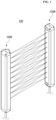
sensor 100 may be referred to as anarea sensor 100, considering that thesensor 100 senses a predetermined area. - Referring to
FIG. 1 , thearea sensor 100 may include anemitter 100E and areceiver 100R. Theemitter 100E may face thereceiver 100R. Theemitter 100E may emit light. Theemitter 100E may include a light emitting element. Theemitter 100E may be referred to as alight emitting unit 100E or alight transmitter 100E. Theemitter 100E may include a plurality of light emitting elements. The plurality of light emitting elements may be arranged in sequence or in series on one surface of theemitter 100E. - The
receiver 100R may sense light. Thereceiver 100R may include a light receiving element. Thereceiver 100R may be referred to as alight receiving unit 100R or alight receiving device 100R. Thereceiver 100R may include a plurality of light receiving elements. The plurality of light receiving elements may be arranged in sequence or in series on one surface of thereceiver 100R. - The light provided by the
emitter 100E may be sensed by thereceiver 100R. If an individual or an object is present between theemitter 100E and thereceiver 100R, the light provided by theemitter 100E is partially blocked, such that the presence of an individual or an object in a sensed area may be sensed. - Referring to
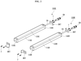
FIG. 2 , theemitter 100E may include ahousing 100E, alight emitting part 120E, and caps 130E and 140E. Thehousing 110E may be elongated and may have a receiving space formed therein. Thelight emitting part 120E may be formed on one surface of thehousing 110E. Thelight emitting part 120E may be elongated on one surface or one side of thehousing 100E along a longitudinal direction of thehousing 110E. Thecaps housing 110E. For example, thelight emitting part 120E and thehousing 110E may be coupled to each other by thecaps - The
emitter 100E may include a cable CA. The cable CA may be electrically connected to thelight emitting part 120E. The cable CA may be connected to an external source on one side of thehousing 110E or thecap 140E. The cable CA has one side electrically connected to thelight emitting part 120E and an opposite side connected to a connector CN. Accordingly, theemitter 100E may receive power or a control signal from an external source. - The
emitter 100E may include a bracket BKT. The bracket BKT may be mounted or coupled to one end or both ends of theemitter 100E. The bracket BKT may be used for installing or mounting theemitter 100E in predetermined equipment. The bracket BKT may be mounted on theemitter 100E by a coupling member f. - The
receiver 100R may include ahousing 110R, alight receiving part 120R, and caps 130R and 140R. Thereceiver 100R may include a cable CA and a bracket BKT. In describing thehousing 110R, thecaps emitter 100E may be equally applied thereto. InFIG. 2 , the description of thelight emitting part 120E may be equally applied to the description of thelight receiving part 120R. - In the following description, the
emitter 100E and thereceiver 100R will be collectively referred to as thesensor 100, without being distinguished from each other. - Referring to
FIG. 3 , thehousing 110 may be elongated and hollow to provide a receiving space. For example, thehousing 110 may have a long cylindrical shape or a square column shape. Thehousing 110 may have an opening 110P1 which is elongated on one surface thereof in a longitudinal direction. The opening 110P1 may be referred to as a first opening 110P1. Thehousing 110 may have an opening 110P2 or openings 110P2 on one end or both ends. The opening 110P2 or openings 110P2 may be referred to as a second opening 110P2 or second openings 110P2. The openings 110P2 may include an upper opening 110P2T and a lower opening 110P2B. The first opening 110P1 may communicate with the second opening 110P2. - The light emitting element and/or the light receiving element may be mounted in the receiving space of the
housing 110. Asensing module 190 may include the light emitting element and/or the light receiving element. - The
cap 130 may close the upper opening 110P2T formed on an upper end of thehousing 110. Further, thecap 140 may close the lower opening 110P2B formed on a lower end of thehousing 110. The structure of both ends of thehousing 110 may be the same. - A sealing
member 160T may be disposed between thecap 130 and one end of thehousing 110. The sealingmember 160T may be disposed around the upper opening 110P2T of thehousing 110. The sealingmember 160T may be referred to as afirst sealing member 160T. Thefirst sealing member 160T may be referred to as anupper sealing member 160T. - The
cover 150 may have a shape of an elongated flat plate and may cover the first opening 110P1 of thehousing 110. Thecover 150 may be referred to as afront cover 150 or alight transmitting cover 150. - A sealing
member 170 may be disposed between thehousing 110 and thecover 150. The sealingmember 170 may referred to as asecond sealing member 170. The second sealing member may be referred to as afront sealing member 170. - Referring to
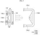
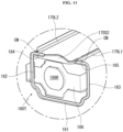
FIGS. 3 to 5 , thefront sealing member 170 may be coated ongrooves housing 110, andgrooves caps grooves grooves 200. Thegrooves grooves grooves grooves - The
front sealing member 170 may have elasticity and/or adhesive strength. The coatedfront sealing member 170 may be cured after the lapse of a predetermined period of time. By coating thefront sealing member 170, a process time may be reduced. - The
front sealing member 170 may include a first longitudinal portion 170L1, a second longitudinal portion 170L2, a first side portion 170S1, and a second side portion 170S2. The first longitudinal portion 170L1 and/or the second longitudinal portion 170L2 may be formed on thegrooves housing 110, and the first side portion 170S1 and/or the second side portion 170S2 may be formed on thegrooves caps - The first side portion 170S1 and/or the second side portion 170S2 may have an overall triangular shape. A center width D2 may be greater than a side width D1. Accordingly, it is possible to prevent components from being separated due to contraction and/or expanding of the front sealing
member 170. - By increasing a contact area between the front sealing
member 170 and thecover 150, waterproofness of the sensor may be improved. - Referring to
FIG. 6 , thehousing 110 may include a bottom 110B and side walls 110S1 and 110S2. The bottom 110B may be an elongated plate. The side walls 110S1 and 110S2 may be disposed opposite each other and may be formed on both sides of the bottom 110B. - The side walls 110S1 and 110S2 may have loops 110R1 and 110R2 formed on an upper side thereof. The loops 110R1 and 110R2 may protrude inwardly of the
housing 110 from the side walls 110S1 and 110S2. - The
grooves groove 210 may be formed in the loop 110R1 and/or the side wall 110S1, and thegroove 220 may be formed in the loop 110R2 and/or the side wall 110S2. Thegrooves cover 150 increases, thecover 150 may be firmly fixed, and waterproofness may be improved. - Dams 110R1S and 110R2S may protrude from the loops 110R1 and 110R2, so as to prevent overflow of the sealing
member 170 to be coated. The dams 110R1S and 110R2S may be referred to as stepped portions 110R1S and 110R2S. - Referring to
FIGS. 7 and8 , the first longitudinal portion 170L1 may form most of a length of thesecond sealing member 170. The first longitudinal portion 170L1 may correspond to a length of the housing 110 (seeFIG. 3 ). The first longitudinal portion 170L1 may have a first horizontal portion 170L1H and a first vertical portion 170L1V. The second longitudinal portion 170L2 may be parallel to the first longitudinal portion 170L1. The second longitudinal portion 170L2 may have a second horizontal portion 170L2H and a second vertical portion 170L2V. The first side portion 170S1 may connect one end of the first longitudinal portion 170L1 and one end of the second longitudinal portion 170L2. The second side portion 170S2 may connect an opposite end of the first longitudinal portion 170L1 and an opposite end of the second longitudinal portion 170L2. - The first longitudinal portion 170L1 may be located in or attached to the
groove 210 of thehousing 110; the second longitudinal portion 170L2 may be located in or attached to thegroove 220 of thehousing 110; the first side portion 170S1 may be located in or attached to thegroove 230 of thecap 130; the second side portion 170S2 may be located in or attached to thegroove 240 of thecap 140. Thesecond sealing member 170 may be symmetrical with respect to a center line CL in a length direction. Thesecond sealing member 170 may be symmetrical with respect to a center line CS in a width direction. - Referring to
FIG. 9 , thecap 130 may have an overall tub shape. Thecap 130 may include a bottom 130B and aside wall 130S. A through-hole 130H may be formed in the bottom 130B. Theside wall 130S may have an upper end surface 130SF which faces and comes into contact with one end surface 111 (seeFIG. 3 ) of the housing (seeFIG. 3 ). Thegroove 300 may be formed on the upper end surface 130SF of theside wall 130S. Thegroove 300 may have an overall C-shape. In this case, an open portion OL of the loop of thegroove 300 may be positioned adjacent to the cover 150 (seeFIG. 3 ) of the sensor. - The
first sealing member 160T may have an overall C-shape corresponding to thegroove 300. Thefirst sealing member 160T may be referred to as theside sealing member 160T. Thefirst sealing member 160T may include afirst part 161, asecond part 162, athird part 163, afourth part 164, afifth part 165, and abridge 166. Thesecond part 162 may be extended by being bent from thefirst part 161. Thethird part 163 may be disposed opposite thesecond part 162, and may be extended by being bent from thefirst part 161. Thefourth part 164 may be extended by being bent from thesecond part 162, and may be disposed opposite thefirst part 161. Thefifth part 165 may be extended by being bent from thethird part 163, and may be disposed opposite thefirst part 161. Thebridge 166 may connect thesecond part 162 and thethird part 163. Thebridge 166 may come into contact with the bottom 130B of thecap 130. A bridge receiving portion 130LB may be recessed from the bottom 130B, and thebridge 166 may be placed in the bridge receiving portion 130LB. Thebridge 166 may not only improve convenience in assembly, but also seals the through-hole 130H and the like formed on thecap 130, thereby improving waterproofness of the sensor. - Referring to
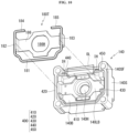
FIG. 10 , thecap 140 may have an overall tub shape. Thecap 140 may include a bottom 140E and aside wall 140S. A through-hole 140H may be formed in the bottom 140H. Theside wall 140S may have an upper end surface 140SF which faces and comes into contact with one end surface 112 (seeFIG. 3 ) of the housing 110 (seeFIG. 3 ). Agroove 400 may be formed on the upper end surface 140SF of theside wall 140S. Thegroove 400 may have an overall C shape. In this case, an open portion OL of the loop of thegroove 400 may be positioned adjacent to the cover 150 (seeFIG. 3 ) of the sensor. - The
cap 140 may have acable hole 140H. Thecable hole 140H may pass through the bottom 140B. - A
third sealing member 180T may have an overall C shape corresponding to thegroove 400. Thethird sealing member 180T may be referred to as aside sealing member 180T. Thethird sealing member 180T may include afirst part 181, asecond part 182, athird part 183, afourth part 184, afifth part 185, and abridge 186. Thesecond part 182 may be extended by being bent from thefirst part 181. Thethird part 183 may be disposed opposite thesecond part 182, and may be extended by being bent from thefirst part 181. Thefourth part 184 may be extended by being bent from thesecond part 182, and may be disposed opposite thefirst part 181. Thefifth part 185 may be extended by being bent from thethird part 183, and may be disposed opposite thefirst part 181. Thebridge 186 may connect thesecond part 182 and thethird part 183. Thebridge 186 may come into contact with the bottom 140B of thecap 140. A bridge receiving portion 140LB may be recessed from the bottom 140B, and thebridge 186 may be placed in the bridge receiving portion 140LB. Thethird sealing member 180T may have acable hole 186H. Thecable hole 186H may pass through thebridge 186. Thebridge 186 may improve convenience in assembly, as well as waterproofness of the sensor. - Referring to
FIGS. 9 to 12 , thesecond sealing member 170 may be connected to thefirst sealing member 160T and/or thethird sealing member 180T. - The connection part CN may connect the first longitudinal portion 170L1 of the
second sealing member 170 and thefourth part 164 of thefirst sealing member 160T. The connection part CN may connect the second longitudinal portion 170L2 of thesecond sealing member 170 and thefifth part 165 of thefirst sealing member 160T. - The connection part CN may connect the first longitudinal portion 170L1 of the
second sealing member 170 and thefifth part 185 of thethird sealing member 180T. The connection part CN may connect the second longitudinal portion 170L2 of thesecond sealing member 170 and thefourth part 184 of thethird sealing member 180T. - The connection parts CN may be formed in insertion grooves IH of the
caps FIG. 5 . Thefirst sealing member 160T, thesecond sealing member 170, and thethird sealing member 180T may be integrally formed in a one-time coating process. - The
column 167 may be formed on an outer surface of thebridge 166, and may be inserted into the through-hole 130H of thecaps hole 130H. - Accordingly, waterproof performance of the sensor may be further improved.
- Referring to
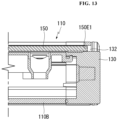
FIG. 13 , thecover 150 may be expanded or contracted depending on external environments (e.g., temperature change), in which the sensor is installed, and may be repeatedly expanded or contracted. Compared to thehousing 110 and/or thecap 130, thecover 150 may be further deformed depending on external environments. - The
cap 130 may have aslot 132. One end 150E1 of thecover 150 may be inserted into theslot 132. In the case where thecover 150, having a different thermal expansion coefficient from thehousing 110 and/or thecap 130, is relatively more deformed due to heat, waterproofness of the sensor may be reduced, but the sealing structure of the sensor described above has an advantage in that the waterproof performance of the sensor may be maintained constant at an initial set level. - Referring to
FIG. 14 , thecap 140 may have aslot 142. An opposite end 150E2 of thecover 150 may be inserted into theslot 142. - Referring to
FIGS. 10 and14 , arubber 500 may be inserted into or fixed to an outer circumference of the cable CA. Therubber 500, having aninclined surface 510 in an insertion direction of the cable CA, may have an overall wedge shape. Awaterproof ring 600 may be inserted into thecable hole 140H. Thewaterproof ring 600 may have an inner surface corresponding to therubber 500. In other words, thewaterproof ring 600 has aninclined surface 610 in the insertion direction of the cable CA, such that when therubber 500 is inserted, thewaterproof ring 600 may be in tight contact with or pressed into therubber 500. While being in tight contact with an outer circumferential surface of the cable CA, therubber 500 may come into tight contact with thewaterproof ring 600, and thewaterproof ring 600 may come into tight contact with thecable hole 140H. Accordingly, waterproofness may be improved around the cable CA. - Some embodiments of the disclosure described above or other embodiments are not mutually exclusive or distinct from each other. Some embodiments of the disclosure described above or other embodiments may be used jointly or combined with each other in configuration or function.
- The above detailed description should not be construed in all aspects as limiting and should be considered illustrative. The scope of the present invention should be determined by the appended claims.
Claims (14)
- A sensor comprising:an elongated and hollow housing (110) having a first opening (110P1) formed in a longitudinal direction of the housing (110), and a second opening (110P2) formed at one end thereof;a cap (130, 140) disposed in the second opening (110P2);an elongated cover (150) covering the first opening (110P1) and having one end coupled to the cap (130, 140);a first receiving groove (210, 220) formed on the housing (110) at a position adjacent to the first opening (110P1) and facing the cover (150);a second receiving groove (230, 240) formed on the cap (130, 140) at a position facing the cover (150);a front sealing member (170) inserted into the first receiving groove (210, 220) and the second receiving groove (230, 240), and coming into contact with the cover (150);a groove (300, 400) formed on the cap (130, 140) at a position adjacent to the second opening (110P2) and facing one end of the housing (110); anda side sealing member (160T, 180T) inserted into the groove (300, 400) and coming into contact with the one end of the housing (110),wherein the front sealing member (170) has:a vertical portion (170L1V, 170L2V) coming into contact with a side surface of the cover (150); anda horizontal portion (170L1H, 170L2H) extending from the vertical portion (170L1V, 170L2V) and coming into contact with an inner surface of the cover (150).
- The sensor of claim 1, wherein in a direction from the cap (130, 140) toward the housing (110), an area of the front sealing member (170), disposed on the second receiving groove, decreases toward the housing (110).
- The sensor of claim 1, wherein the front sealing member (170), disposed on the first receiving groove (210, 220), comes into contact with at least two surfaces of the cover (150) based on an edge of the cover (150) facing the first receiving groove (210, 220).
- The sensor of claim 1, wherein the cap (130, 140) further comprises:an insertion groove (IH) connecting the second receiving groove (230, 240) and the groove (300, 400); anda connection part (CN) disposed in the insertion groove (IH) and connecting the front sealing member (170) and the side sealing member (160T, 180T).
- The sensor of claim 1, wherein:
the cap (140) has a bottom (140B) facing the second opening (110P2B) of the housing (110), a side wall (140S) formed around the bottom (140B), and a cable hole (140H) formed by passing through the bottom (140B); andthe side sealing member (180T) has parts (181, 182, 183, 184, 185) disposed in the groove (400), and a bridge (186) connecting the parts (182, 183) across the bottom (140B),wherein the bridge (186) is coupled to the bottom (140B). - The sensor of claim 5, further comprising:a cable (CA) inserted into the cable hole (140H);a waterproof ring (600) inserted into the cable hole (140H) and coming into contact with the cable hole (140H); anda rubber (500) coming into contact with an outer circumferential surface of the cable (CA) and inserted into the waterproof ring (600) to be in tight contact with the waterproof ring (600).
- The sensor of claim 6, wherein the waterproof ring (600) and the rubber (500) have inclined surfaces (510, 610) corresponding to each other.
- The sensor of claim 1, wherein the cap (130, 140) has a slot (132, 142) disposed adjacent to one end (150E1, 150E2) of the cover (150),
wherein the one end (150E1, 150E2) of the cover (150) is inserted into the slot (132, 142). - The sensor of claim 8, wherein a space is formed between the one end (150E1, 150E2) of the cover (150) and the slot (132, 142).
- The sensor of claim 1, wherein:the cap (130) has a bottom (130B) facing the second opening (110P2T) of the housing (110), a side wall (130S) formed around the bottom (130B), and a through-hole (130H) formed in the bottom (130B); andthe side sealing member (160T) has parts (161, 162, 163, 164, 165) disposed in the groove (300), a bridge (166) connecting the parts (162, 163), and a column (167) formed on an outer surface of the bridge (166) and inserted into the through-hole (130H).
- The sensor of claim 1, wherein the cover (150) is attached to the front sealing member (170).
- The sensor of claim 1, further comprising a light emitting part or a light receiving part installed in the housing (110),
wherein the cover (150) is formed as a light transmitting plate. - The sensor of claim 1, wherein the housing (110) has:a bottom (110B) extending in a longitudinal direction;a side wall (110S1, 110S2) formed around the bottom (110B);a loop (110R1, 110R2) protruding inwardly from the side wall (110S1, 110S2), wherein the first receiving groove (210, 220) is formed in the loop (110R1, 110R2); anda dam (110R1S, 110R2S) protruding from the loop (110R1, 110R2) toward the cover (150).
- The sensor of claim 1, wherein the front sealing member (170) comprises:a side portion (170S1, 170S2) formed on the second receiving groove (230, 240); anda longitudinal portion (170L1, 170L2) formed on the first receiving groove (210, 220) and extending from the side portion (170S1, 170S2),wherein the longitudinal portion (170L1, 170L2) comprises the vertical portion (170L1V, 170L2V) and the horizontal portion (170L1H, 170L2H).
Applications Claiming Priority (2)
| Application Number | Priority Date | Filing Date | Title |
|---|---|---|---|
| KR1020190035932A KR20200114345A (en) | 2019-03-28 | 2019-03-28 | Sensor |
| PCT/KR2020/003005 WO2020197114A1 (en) | 2019-03-28 | 2020-03-03 | Sensor |
Publications (3)
| Publication Number | Publication Date |
|---|---|
| EP3951438A1 EP3951438A1 (en) | 2022-02-09 |
| EP3951438A4 EP3951438A4 (en) | 2022-12-21 |
| EP3951438B1 true EP3951438B1 (en) | 2025-02-19 |
Family
ID=72610263
Family Applications (1)
| Application Number | Title | Priority Date | Filing Date |
|---|---|---|---|
| EP20779992.5A Active EP3951438B1 (en) | 2019-03-28 | 2020-03-03 | Sensor |
Country Status (5)
| Country | Link |
|---|---|
| US (1) | US11920954B2 (en) |
| EP (1) | EP3951438B1 (en) |
| KR (1) | KR20200114345A (en) |
| CN (1) | CN113631961B (en) |
| WO (1) | WO2020197114A1 (en) |
Families Citing this family (1)
| Publication number | Priority date | Publication date | Assignee | Title |
|---|---|---|---|---|
| EP4242700A4 (en) * | 2020-11-03 | 2024-08-21 | Autonics Corporation | Sensor and locking device therefor |
Family Cites Families (23)
| Publication number | Priority date | Publication date | Assignee | Title |
|---|---|---|---|---|
| GB1486364A (en) * | 1974-07-15 | 1977-09-21 | Dawson S | Temperature probe covers |
| JP3244839B2 (en) * | 1993-02-01 | 2002-01-07 | 旭テック株式会社 | Packing for manhole cover |
| AU687363B2 (en) * | 1993-03-19 | 1998-02-26 | Ciba Corning Diagnostics Corp. | Luminometer |
| KR100822037B1 (en) * | 2006-12-18 | 2008-04-15 | 엄세범 | Bar type lighting fixtures |
| CN101391529A (en) * | 2008-11-05 | 2009-03-25 | 孙荣华 | Split type ink box with light transmitting window |
| JP5138613B2 (en) * | 2009-01-15 | 2013-02-06 | 四変テック株式会社 | Lighting device |
| JP5141825B2 (en) * | 2009-07-30 | 2013-02-13 | オムロン株式会社 | Multi-axis photoelectric sensor |
| KR200453689Y1 (en) * | 2009-10-13 | 2011-05-23 | 비전엑스아시아 주식회사 | Car LED Bar Lighting |
| CN102735723B (en) * | 2011-04-05 | 2015-12-02 | 费加罗技研株式会社 | Electrochemical gas sensor and clinching method thereof |
| KR101126586B1 (en) * | 2011-11-04 | 2012-03-23 | 김종천 | Sealing structure of lighting apparatus |
| JP5912641B2 (en) * | 2012-02-20 | 2016-04-27 | 日本ピラー工業株式会社 | Mounting structure for fluid measurement sensor |
| KR20140130884A (en) * | 2013-05-02 | 2014-11-12 | 주식회사 포스코엘이디 | Optical semiconductor illuminating apparatus |
| AU2014268532A1 (en) * | 2013-05-23 | 2015-12-10 | Meyer Intellectual Properties Ltd. | Low-pressure cooking method and cookware vessel adapted for the same |
| JP6475544B2 (en) * | 2015-03-31 | 2019-02-27 | パナソニック デバイスSunx株式会社 | Multi-axis photoelectric sensor |
| EP3101244B1 (en) * | 2015-06-01 | 2021-04-07 | Mann + Hummel Gmbh | Sealing element, ring filter element, oil separator and method for opening the filter housing of an oil separator |
| KR20160148316A (en) * | 2015-06-16 | 2016-12-26 | 삼성에스디아이 주식회사 | Rechargeable battery |
| CN107348849B (en) * | 2016-05-10 | 2020-09-29 | 佛山市顺德区美的电热电器制造有限公司 | Shell assembly and cooking utensil |
| JP2018010790A (en) | 2016-07-13 | 2018-01-18 | オムロン株式会社 | Multi-axis photoelectric sensor |
| JP6763222B2 (en) * | 2016-07-13 | 2020-09-30 | オムロン株式会社 | Multi-optical axis photoelectric sensor |
| JP2018010788A (en) | 2016-07-13 | 2018-01-18 | オムロン株式会社 | Multi-axis photoelectric sensor |
| CN106329212B (en) * | 2016-10-13 | 2019-04-19 | Oppo广东移动通信有限公司 | Mobile terminal, earphone seat and manufacturing method of earphone seat |
| KR102449221B1 (en) * | 2017-04-04 | 2022-09-29 | 주식회사 오토닉스 | sensor |
| CN207736659U (en) * | 2018-01-18 | 2018-08-17 | 奥托尼克斯电子(嘉兴)有限公司 | The encapsulation die of photoelectric sensor sealing |
-
2019
- 2019-03-28 KR KR1020190035932A patent/KR20200114345A/en not_active Ceased
-
2020
- 2020-03-03 WO PCT/KR2020/003005 patent/WO2020197114A1/en not_active Ceased
- 2020-03-03 EP EP20779992.5A patent/EP3951438B1/en active Active
- 2020-03-03 US US17/439,259 patent/US11920954B2/en active Active
- 2020-03-03 CN CN202080024260.6A patent/CN113631961B/en active Active
Also Published As
| Publication number | Publication date |
|---|---|
| KR20200114345A (en) | 2020-10-07 |
| US11920954B2 (en) | 2024-03-05 |
| EP3951438A1 (en) | 2022-02-09 |
| EP3951438A4 (en) | 2022-12-21 |
| WO2020197114A1 (en) | 2020-10-01 |
| CN113631961A (en) | 2021-11-09 |
| CN113631961B (en) | 2025-03-11 |
| US20220155110A1 (en) | 2022-05-19 |
Similar Documents
| Publication | Publication Date | Title |
|---|---|---|
| US7476848B2 (en) | Optical sensor employing an injection-molded casing | |
| EP3270189B1 (en) | Multiple-optical-axis photoelectric sensor | |
| KR102186933B1 (en) | Sensor module and auto defog sensor | |
| JP2005276656A (en) | Tamper switch structure and crime-prevention sensor equipped therewith | |
| EP3951438A1 (en) | Sensor | |
| US20180017434A1 (en) | Multiple-optical-axis photoelectric sensor | |
| US20180017435A1 (en) | Multiple-optical-axis photoelectric sensor | |
| KR102887063B1 (en) | Camera module | |
| JP2009272064A (en) | Multiple optical-axis photoelectric sensor | |
| KR20200124196A (en) | Sensor | |
| JP2002075149A (en) | Multi-optical axis photoelectric sensor | |
| KR102456655B1 (en) | Sensor | |
| US11035554B2 (en) | Motion sensitive lamp with coupling mechanism | |
| CN210801081U (en) | Slender microwave inductor | |
| KR102305946B1 (en) | detection device and air conditioner | |
| CN219514160U (en) | Monitoring device | |
| CN217952098U (en) | Lighting lamp and lampshade | |
| JP5046297B2 (en) | Multi-axis photoelectric sensor | |
| CN220623973U (en) | LED lamp | |
| CN217159835U (en) | Infrared dome camera dome cover | |
| KR102341530B1 (en) | Sensor | |
| CN215914459U (en) | Sensor and cleaning device | |
| CN220355370U (en) | Integrated flexible wall washer lamp | |
| KR20160015148A (en) | Photoelectric sensor and mehtod for manufacturing photoelectric seonsor | |
| JP4265961B2 (en) | Multi-optical axis photoelectric sensor projector and receiver |
Legal Events
| Date | Code | Title | Description |
|---|---|---|---|
| STAA | Information on the status of an ep patent application or granted ep patent |
Free format text: STATUS: THE INTERNATIONAL PUBLICATION HAS BEEN MADE |
|
| PUAI | Public reference made under article 153(3) epc to a published international application that has entered the european phase |
Free format text: ORIGINAL CODE: 0009012 |
|
| STAA | Information on the status of an ep patent application or granted ep patent |
Free format text: STATUS: REQUEST FOR EXAMINATION WAS MADE |
|
| 17P | Request for examination filed |
Effective date: 20210908 |
|
| AK | Designated contracting states |
Kind code of ref document: A1 Designated state(s): AL AT BE BG CH CY CZ DE DK EE ES FI FR GB GR HR HU IE IS IT LI LT LU LV MC MK MT NL NO PL PT RO RS SE SI SK SM TR |
|
| DAV | Request for validation of the european patent (deleted) | ||
| DAX | Request for extension of the european patent (deleted) | ||
| A4 | Supplementary search report drawn up and despatched |
Effective date: 20221122 |
|
| RIC1 | Information provided on ipc code assigned before grant |
Ipc: G01D 11/26 20060101ALI20221116BHEP Ipc: G01D 11/24 20060101ALI20221116BHEP Ipc: G01V 8/20 20060101AFI20221116BHEP |
|
| GRAP | Despatch of communication of intention to grant a patent |
Free format text: ORIGINAL CODE: EPIDOSNIGR1 |
|
| STAA | Information on the status of an ep patent application or granted ep patent |
Free format text: STATUS: GRANT OF PATENT IS INTENDED |
|
| INTG | Intention to grant announced |
Effective date: 20240924 |
|
| GRAS | Grant fee paid |
Free format text: ORIGINAL CODE: EPIDOSNIGR3 |
|
| GRAA | (expected) grant |
Free format text: ORIGINAL CODE: 0009210 |
|
| STAA | Information on the status of an ep patent application or granted ep patent |
Free format text: STATUS: THE PATENT HAS BEEN GRANTED |
|
| P01 | Opt-out of the competence of the unified patent court (upc) registered |
Free format text: CASE NUMBER: APP_67677/2024 Effective date: 20241223 |
|
| AK | Designated contracting states |
Kind code of ref document: B1 Designated state(s): AL AT BE BG CH CY CZ DE DK EE ES FI FR GB GR HR HU IE IS IT LI LT LU LV MC MK MT NL NO PL PT RO RS SE SI SK SM TR |
|
| REG | Reference to a national code |
Ref country code: GB Ref legal event code: FG4D |
|
| REG | Reference to a national code |
Ref country code: CH Ref legal event code: EP |
|
| REG | Reference to a national code |
Ref country code: IE Ref legal event code: FG4D |
|
| REG | Reference to a national code |
Ref country code: DE Ref legal event code: R096 Ref document number: 602020046359 Country of ref document: DE |
|
| REG | Reference to a national code |
Ref country code: NL Ref legal event code: MP Effective date: 20250219 |
|
| PG25 | Lapsed in a contracting state [announced via postgrant information from national office to epo] |
Ref country code: RS Free format text: LAPSE BECAUSE OF FAILURE TO SUBMIT A TRANSLATION OF THE DESCRIPTION OR TO PAY THE FEE WITHIN THE PRESCRIBED TIME-LIMIT Effective date: 20250519 |
|
| PG25 | Lapsed in a contracting state [announced via postgrant information from national office to epo] |
Ref country code: FI Free format text: LAPSE BECAUSE OF FAILURE TO SUBMIT A TRANSLATION OF THE DESCRIPTION OR TO PAY THE FEE WITHIN THE PRESCRIBED TIME-LIMIT Effective date: 20250219 |
|
| PG25 | Lapsed in a contracting state [announced via postgrant information from national office to epo] |
Ref country code: PL Free format text: LAPSE BECAUSE OF FAILURE TO SUBMIT A TRANSLATION OF THE DESCRIPTION OR TO PAY THE FEE WITHIN THE PRESCRIBED TIME-LIMIT Effective date: 20250219 |
|
| PG25 | Lapsed in a contracting state [announced via postgrant information from national office to epo] |
Ref country code: ES Free format text: LAPSE BECAUSE OF FAILURE TO SUBMIT A TRANSLATION OF THE DESCRIPTION OR TO PAY THE FEE WITHIN THE PRESCRIBED TIME-LIMIT Effective date: 20250219 |
|
| REG | Reference to a national code |
Ref country code: LT Ref legal event code: MG9D |
|
| PG25 | Lapsed in a contracting state [announced via postgrant information from national office to epo] |
Ref country code: NO Free format text: LAPSE BECAUSE OF FAILURE TO SUBMIT A TRANSLATION OF THE DESCRIPTION OR TO PAY THE FEE WITHIN THE PRESCRIBED TIME-LIMIT Effective date: 20250519 Ref country code: IS Free format text: LAPSE BECAUSE OF FAILURE TO SUBMIT A TRANSLATION OF THE DESCRIPTION OR TO PAY THE FEE WITHIN THE PRESCRIBED TIME-LIMIT Effective date: 20250619 |
|
| PG25 | Lapsed in a contracting state [announced via postgrant information from national office to epo] |
Ref country code: NL Free format text: LAPSE BECAUSE OF FAILURE TO SUBMIT A TRANSLATION OF THE DESCRIPTION OR TO PAY THE FEE WITHIN THE PRESCRIBED TIME-LIMIT Effective date: 20250219 |
|
| PG25 | Lapsed in a contracting state [announced via postgrant information from national office to epo] |
Ref country code: HR Free format text: LAPSE BECAUSE OF FAILURE TO SUBMIT A TRANSLATION OF THE DESCRIPTION OR TO PAY THE FEE WITHIN THE PRESCRIBED TIME-LIMIT Effective date: 20250219 |
|
| PG25 | Lapsed in a contracting state [announced via postgrant information from national office to epo] |
Ref country code: PT Free format text: LAPSE BECAUSE OF FAILURE TO SUBMIT A TRANSLATION OF THE DESCRIPTION OR TO PAY THE FEE WITHIN THE PRESCRIBED TIME-LIMIT Effective date: 20250620 Ref country code: LV Free format text: LAPSE BECAUSE OF FAILURE TO SUBMIT A TRANSLATION OF THE DESCRIPTION OR TO PAY THE FEE WITHIN THE PRESCRIBED TIME-LIMIT Effective date: 20250219 |
|
| PG25 | Lapsed in a contracting state [announced via postgrant information from national office to epo] |
Ref country code: GR Free format text: LAPSE BECAUSE OF FAILURE TO SUBMIT A TRANSLATION OF THE DESCRIPTION OR TO PAY THE FEE WITHIN THE PRESCRIBED TIME-LIMIT Effective date: 20250520 Ref country code: BG Free format text: LAPSE BECAUSE OF FAILURE TO SUBMIT A TRANSLATION OF THE DESCRIPTION OR TO PAY THE FEE WITHIN THE PRESCRIBED TIME-LIMIT Effective date: 20250219 |
|
| REG | Reference to a national code |
Ref country code: AT Ref legal event code: MK05 Ref document number: 1768784 Country of ref document: AT Kind code of ref document: T Effective date: 20250219 |
|
| PG25 | Lapsed in a contracting state [announced via postgrant information from national office to epo] |
Ref country code: SE Free format text: LAPSE BECAUSE OF FAILURE TO SUBMIT A TRANSLATION OF THE DESCRIPTION OR TO PAY THE FEE WITHIN THE PRESCRIBED TIME-LIMIT Effective date: 20250219 |
|
| PG25 | Lapsed in a contracting state [announced via postgrant information from national office to epo] |
Ref country code: SM Free format text: LAPSE BECAUSE OF FAILURE TO SUBMIT A TRANSLATION OF THE DESCRIPTION OR TO PAY THE FEE WITHIN THE PRESCRIBED TIME-LIMIT Effective date: 20250219 |
|
| PG25 | Lapsed in a contracting state [announced via postgrant information from national office to epo] |
Ref country code: DK Free format text: LAPSE BECAUSE OF FAILURE TO SUBMIT A TRANSLATION OF THE DESCRIPTION OR TO PAY THE FEE WITHIN THE PRESCRIBED TIME-LIMIT Effective date: 20250219 |
|
| PG25 | Lapsed in a contracting state [announced via postgrant information from national office to epo] |
Ref country code: AT Free format text: LAPSE BECAUSE OF FAILURE TO SUBMIT A TRANSLATION OF THE DESCRIPTION OR TO PAY THE FEE WITHIN THE PRESCRIBED TIME-LIMIT Effective date: 20250219 |
|
| PG25 | Lapsed in a contracting state [announced via postgrant information from national office to epo] |
Ref country code: EE Free format text: LAPSE BECAUSE OF FAILURE TO SUBMIT A TRANSLATION OF THE DESCRIPTION OR TO PAY THE FEE WITHIN THE PRESCRIBED TIME-LIMIT Effective date: 20250219 Ref country code: CZ Free format text: LAPSE BECAUSE OF FAILURE TO SUBMIT A TRANSLATION OF THE DESCRIPTION OR TO PAY THE FEE WITHIN THE PRESCRIBED TIME-LIMIT Effective date: 20250219 |
|
| PG25 | Lapsed in a contracting state [announced via postgrant information from national office to epo] |
Ref country code: RO Free format text: LAPSE BECAUSE OF FAILURE TO SUBMIT A TRANSLATION OF THE DESCRIPTION OR TO PAY THE FEE WITHIN THE PRESCRIBED TIME-LIMIT Effective date: 20250219 |
|
| REG | Reference to a national code |
Ref country code: CH Ref legal event code: H13 Free format text: ST27 STATUS EVENT CODE: U-0-0-H10-H13 (AS PROVIDED BY THE NATIONAL OFFICE) Effective date: 20251024 |
|
| PG25 | Lapsed in a contracting state [announced via postgrant information from national office to epo] |
Ref country code: SK Free format text: LAPSE BECAUSE OF FAILURE TO SUBMIT A TRANSLATION OF THE DESCRIPTION OR TO PAY THE FEE WITHIN THE PRESCRIBED TIME-LIMIT Effective date: 20250219 |
|
| PG25 | Lapsed in a contracting state [announced via postgrant information from national office to epo] |
Ref country code: LU Free format text: LAPSE BECAUSE OF NON-PAYMENT OF DUE FEES Effective date: 20250303 |
|
| REG | Reference to a national code |
Ref country code: DE Ref legal event code: R097 Ref document number: 602020046359 Country of ref document: DE |
|
| REG | Reference to a national code |
Ref country code: BE Ref legal event code: MM Effective date: 20250331 |
|
| PG25 | Lapsed in a contracting state [announced via postgrant information from national office to epo] |
Ref country code: MC Free format text: LAPSE BECAUSE OF FAILURE TO SUBMIT A TRANSLATION OF THE DESCRIPTION OR TO PAY THE FEE WITHIN THE PRESCRIBED TIME-LIMIT Effective date: 20250219 |
|
| PLBE | No opposition filed within time limit |
Free format text: ORIGINAL CODE: 0009261 |
|
| STAA | Information on the status of an ep patent application or granted ep patent |
Free format text: STATUS: NO OPPOSITION FILED WITHIN TIME LIMIT |
|
| PG25 | Lapsed in a contracting state [announced via postgrant information from national office to epo] |
Ref country code: FR Free format text: LAPSE BECAUSE OF NON-PAYMENT OF DUE FEES Effective date: 20250419 |
|
| PG25 | Lapsed in a contracting state [announced via postgrant information from national office to epo] |
Ref country code: BE Free format text: LAPSE BECAUSE OF NON-PAYMENT OF DUE FEES Effective date: 20250331 |
|
| PG25 | Lapsed in a contracting state [announced via postgrant information from national office to epo] |
Ref country code: CH Free format text: LAPSE BECAUSE OF NON-PAYMENT OF DUE FEES Effective date: 20250331 |
|
| PG25 | Lapsed in a contracting state [announced via postgrant information from national office to epo] |
Ref country code: IE Free format text: LAPSE BECAUSE OF NON-PAYMENT OF DUE FEES Effective date: 20250303 |
|
| 26N | No opposition filed |
Effective date: 20251120 |
|
| GBPC | Gb: european patent ceased through non-payment of renewal fee |
Effective date: 20250519 |
|
| PG25 | Lapsed in a contracting state [announced via postgrant information from national office to epo] |
Ref country code: GB Free format text: LAPSE BECAUSE OF NON-PAYMENT OF DUE FEES Effective date: 20250519 |
|
| PGFP | Annual fee paid to national office [announced via postgrant information from national office to epo] |
Ref country code: DE Payment date: 20260220 Year of fee payment: 7 |
|
| PGFP | Annual fee paid to national office [announced via postgrant information from national office to epo] |
Ref country code: IT Payment date: 20260223 Year of fee payment: 7 |