EP3951410A1 - Apparatus and method for diagnosing battery cell - Google Patents
Apparatus and method for diagnosing battery cell Download PDFInfo
- Publication number
- EP3951410A1 EP3951410A1 EP20802564.3A EP20802564A EP3951410A1 EP 3951410 A1 EP3951410 A1 EP 3951410A1 EP 20802564 A EP20802564 A EP 20802564A EP 3951410 A1 EP3951410 A1 EP 3951410A1
- Authority
- EP
- European Patent Office
- Prior art keywords
- voltage
- unit
- battery
- cell
- battery pack
- Prior art date
- Legal status (The legal status is an assumption and is not a legal conclusion. Google has not performed a legal analysis and makes no representation as to the accuracy of the status listed.)
- Granted
Links
Images




Classifications
-
- G—PHYSICS
- G01—MEASURING; TESTING
- G01R—MEASURING ELECTRIC VARIABLES; MEASURING MAGNETIC VARIABLES
- G01R31/00—Arrangements for testing electric properties; Arrangements for locating electric faults; Arrangements for electrical testing characterised by what is being tested not provided for elsewhere
- G01R31/36—Arrangements for testing, measuring or monitoring the electrical condition of accumulators or electric batteries, e.g. capacity or state of charge [SoC]
- G01R31/392—Determining battery ageing or deterioration, e.g. state of health
-
- G—PHYSICS
- G01—MEASURING; TESTING
- G01R—MEASURING ELECTRIC VARIABLES; MEASURING MAGNETIC VARIABLES
- G01R19/00—Arrangements for measuring currents or voltages or for indicating presence or sign thereof
- G01R19/0038—Circuits for comparing several input signals and for indicating the result of this comparison, e.g. equal, different, greater, smaller (comparing pulses or pulse trains according to amplitude)
-
- G—PHYSICS
- G01—MEASURING; TESTING
- G01R—MEASURING ELECTRIC VARIABLES; MEASURING MAGNETIC VARIABLES
- G01R19/00—Arrangements for measuring currents or voltages or for indicating presence or sign thereof
- G01R19/10—Measuring sum, difference or ratio
-
- G—PHYSICS
- G01—MEASURING; TESTING
- G01R—MEASURING ELECTRIC VARIABLES; MEASURING MAGNETIC VARIABLES
- G01R19/00—Arrangements for measuring currents or voltages or for indicating presence or sign thereof
- G01R19/25—Arrangements for measuring currents or voltages or for indicating presence or sign thereof using digital measurement techniques
-
- G—PHYSICS
- G01—MEASURING; TESTING
- G01R—MEASURING ELECTRIC VARIABLES; MEASURING MAGNETIC VARIABLES
- G01R31/00—Arrangements for testing electric properties; Arrangements for locating electric faults; Arrangements for electrical testing characterised by what is being tested not provided for elsewhere
- G01R31/36—Arrangements for testing, measuring or monitoring the electrical condition of accumulators or electric batteries, e.g. capacity or state of charge [SoC]
- G01R31/382—Arrangements for monitoring battery or accumulator variables, e.g. SoC
- G01R31/3842—Arrangements for monitoring battery or accumulator variables, e.g. SoC combining voltage and current measurements
-
- G—PHYSICS
- G01—MEASURING; TESTING
- G01R—MEASURING ELECTRIC VARIABLES; MEASURING MAGNETIC VARIABLES
- G01R31/00—Arrangements for testing electric properties; Arrangements for locating electric faults; Arrangements for electrical testing characterised by what is being tested not provided for elsewhere
- G01R31/36—Arrangements for testing, measuring or monitoring the electrical condition of accumulators or electric batteries, e.g. capacity or state of charge [SoC]
- G01R31/389—Measuring internal impedance, internal conductance or related variables
-
- G—PHYSICS
- G01—MEASURING; TESTING
- G01R—MEASURING ELECTRIC VARIABLES; MEASURING MAGNETIC VARIABLES
- G01R31/00—Arrangements for testing electric properties; Arrangements for locating electric faults; Arrangements for electrical testing characterised by what is being tested not provided for elsewhere
- G01R31/36—Arrangements for testing, measuring or monitoring the electrical condition of accumulators or electric batteries, e.g. capacity or state of charge [SoC]
- G01R31/396—Acquisition or processing of data for testing or for monitoring individual cells or groups of cells within a battery
-
- G—PHYSICS
- G01—MEASURING; TESTING
- G01R—MEASURING ELECTRIC VARIABLES; MEASURING MAGNETIC VARIABLES
- G01R31/00—Arrangements for testing electric properties; Arrangements for locating electric faults; Arrangements for electrical testing characterised by what is being tested not provided for elsewhere
- G01R31/50—Testing of electric apparatus, lines, cables or components for short-circuits, continuity, leakage current or incorrect line connections
- G01R31/58—Testing of lines, cables or conductors
-
- G—PHYSICS
- G01—MEASURING; TESTING
- G01R—MEASURING ELECTRIC VARIABLES; MEASURING MAGNETIC VARIABLES
- G01R31/00—Arrangements for testing electric properties; Arrangements for locating electric faults; Arrangements for electrical testing characterised by what is being tested not provided for elsewhere
- G01R31/50—Testing of electric apparatus, lines, cables or components for short-circuits, continuity, leakage current or incorrect line connections
- G01R31/66—Testing of connections, e.g. of plugs or non-disconnectable joints
-
- H—ELECTRICITY
- H01—ELECTRIC ELEMENTS
- H01M—PROCESSES OR MEANS, e.g. BATTERIES, FOR THE DIRECT CONVERSION OF CHEMICAL ENERGY INTO ELECTRICAL ENERGY
- H01M10/00—Secondary cells; Manufacture thereof
- H01M10/42—Methods or arrangements for servicing or maintenance of secondary cells or secondary half-cells
- H01M10/425—Structural combination with electronic components, e.g. electronic circuits integrated to the outside of the casing
-
- H—ELECTRICITY
- H01—ELECTRIC ELEMENTS
- H01M—PROCESSES OR MEANS, e.g. BATTERIES, FOR THE DIRECT CONVERSION OF CHEMICAL ENERGY INTO ELECTRICAL ENERGY
- H01M10/00—Secondary cells; Manufacture thereof
- H01M10/42—Methods or arrangements for servicing or maintenance of secondary cells or secondary half-cells
- H01M10/48—Accumulators combined with arrangements for measuring, testing or indicating the condition of cells, e.g. the level or density of the electrolyte
-
- H—ELECTRICITY
- H01—ELECTRIC ELEMENTS
- H01M—PROCESSES OR MEANS, e.g. BATTERIES, FOR THE DIRECT CONVERSION OF CHEMICAL ENERGY INTO ELECTRICAL ENERGY
- H01M10/00—Secondary cells; Manufacture thereof
- H01M10/42—Methods or arrangements for servicing or maintenance of secondary cells or secondary half-cells
- H01M10/48—Accumulators combined with arrangements for measuring, testing or indicating the condition of cells, e.g. the level or density of the electrolyte
- H01M10/482—Accumulators combined with arrangements for measuring, testing or indicating the condition of cells, e.g. the level or density of the electrolyte for several batteries or cells simultaneously or sequentially
-
- H—ELECTRICITY
- H02—GENERATION; CONVERSION OR DISTRIBUTION OF ELECTRIC POWER
- H02J—ELECTRIC POWER NETWORKS; CIRCUIT ARRANGEMENTS OR SYSTEMS FOR SUPPLYING OR DISTRIBUTING ELECTRIC POWER; SYSTEMS FOR STORING ELECTRIC ENERGY
- H02J7/00—Circuit arrangements for charging or discharging batteries or for supplying loads from batteries
- H02J7/80—Circuit arrangements for charging or discharging batteries or for supplying loads from batteries including monitoring or indicating arrangements
-
- G—PHYSICS
- G01—MEASURING; TESTING
- G01R—MEASURING ELECTRIC VARIABLES; MEASURING MAGNETIC VARIABLES
- G01R19/00—Arrangements for measuring currents or voltages or for indicating presence or sign thereof
- G01R19/165—Indicating that current or voltage is either above or below a predetermined value or within or outside a predetermined range of values
- G01R19/16533—Indicating that current or voltage is either above or below a predetermined value or within or outside a predetermined range of values characterised by the application
- G01R19/16538—Indicating that current or voltage is either above or below a predetermined value or within or outside a predetermined range of values characterised by the application in AC or DC supplies
- G01R19/16542—Indicating that current or voltage is either above or below a predetermined value or within or outside a predetermined range of values characterised by the application in AC or DC supplies for batteries
-
- H—ELECTRICITY
- H01—ELECTRIC ELEMENTS
- H01M—PROCESSES OR MEANS, e.g. BATTERIES, FOR THE DIRECT CONVERSION OF CHEMICAL ENERGY INTO ELECTRICAL ENERGY
- H01M10/00—Secondary cells; Manufacture thereof
- H01M10/42—Methods or arrangements for servicing or maintenance of secondary cells or secondary half-cells
- H01M10/425—Structural combination with electronic components, e.g. electronic circuits integrated to the outside of the casing
- H01M2010/4271—Battery management systems including electronic circuits, e.g. control of current or voltage to keep battery in healthy state, cell balancing
-
- Y—GENERAL TAGGING OF NEW TECHNOLOGICAL DEVELOPMENTS; GENERAL TAGGING OF CROSS-SECTIONAL TECHNOLOGIES SPANNING OVER SEVERAL SECTIONS OF THE IPC; TECHNICAL SUBJECTS COVERED BY FORMER USPC CROSS-REFERENCE ART COLLECTIONS [XRACs] AND DIGESTS
- Y02—TECHNOLOGIES OR APPLICATIONS FOR MITIGATION OR ADAPTATION AGAINST CLIMATE CHANGE
- Y02E—REDUCTION OF GREENHOUSE GAS [GHG] EMISSIONS, RELATED TO ENERGY GENERATION, TRANSMISSION OR DISTRIBUTION
- Y02E60/00—Enabling technologies; Technologies with a potential or indirect contribution to GHG emissions mitigation
- Y02E60/10—Energy storage using batteries
Definitions
- the present invention relates to a device and method for diagnosing an increase in resistance of a lead unit of a battery cell.
- An aspect of the present invention provides a battery cell diagnostic device and method for rapidly diagnosing resistance of a lead unit of a unit cell upon charging and discharging a battery to raise stability of the battery, when the battery includes at least a plurality of unit cells connected in series.
- a battery cell diagnostic device including: a voltage measurement unit configured to measure a voltage between both ends of each unit cell of a battery pack; a current measurement unit configured to measure a current of the battery pack; and a detection unit configured to compare a first voltage measured for each of the unit cells when the battery pack is in an open circuit voltage state with a second voltage measured for each of the unit cells according to a predetermined current flowing through the battery pack, when the battery pack is in a charged or discharged state, and detect whether each of the unit cells is abnormal.
- the voltage measurement unit may include: a multiplexer of which measurement terminals are respectively connected to lead units between the unit cells and lead units of both outermost unit cells with respect to at least a plurality of the unit cells connected in series, and which outputs a measurement voltage from measurement terminals of both ends of one unit cell according to a preset measurement condition; and an analog-to-digital converter (ADC) configured to analog-to-digitally converts the measurement voltage output from the multiplexer.
- ADC analog-to-digital converter
- the detection unit may determine whether a voltage difference between the first voltage and the second voltage exceeds a predetermined reference value to detect whether the unit cell is abnormal. In response to the abnormality of the unit cell being detected, the detection unit may determine that resistance equal to or greater than a predetermined reference value is present in a part of the lead units of both ends of the unit cell.
- the detection unit may generate a notification signal for the unit cell.
- the battery cell diagnostic device may further include a memory configured to store at least one between the first voltage and the second voltage.
- a battery cell diagnostic method including: a first voltage measurement step in which when a battery pack is in an open circuit voltage state, a voltage is measured for each unit cell of the battery pack; a second voltage measurement step in which, when the battery pack is in a charging or discharging state, a voltage is measured for each unit cell according to a predetermined current flowing through the battery pack; and a step for comparing, for each unit cell, a voltage measured in the first voltage measurement step and a voltage measured in the second voltage measurement step, and detecting whether the unit cell is abnormal.
- whether the unit cell is abnormal may be detected by determining that a voltage difference between the first voltage and the second voltage exceeds a predetermined reference value. As an example, in response to the abnormality of the unit cell being detected, it may be determined that resistance equal to or greater than a predetermined reference value is present in a part of the lead units of both ends of the unit cell.
- the battery cell diagnostic method may further include a step for generating a notification signal for the unit cell, in response to the abnormality of the unit cell being detected.
- a battery pack including: a battery module including at least a plurality of unit cells connected in series; and a battery management system configured to control charging and discharging the battery module, wherein the battery management system may include: a voltage measurement unit configured to measure a voltage between both ends of each of the unit cells; a current measurement unit configured to measure a current of the battery module; and a detection unit configured to compare a first voltage measured for each of the unit cells when the battery pack is in an open circuit voltage state with a second voltage measured for each of the unit cells according to a predetermined current flowing through the battery pack, when the battery pack is in a charging or discharging state, and to detect whether each of the unit cells is abnormal.
- resistance of a lead unit of a unit cell upon charging and discharging a battery may be rapidly diagnosed to raise the stability of the battery.
- first, second, A, B, (a), and (b) may be used. Such terms are used only for distinguishing an element from another element, but do not limit the substance of the element, sequence or order. It should be noted that if it is described in the specification that one element is “connected,” “coupled” or “joined” to another element, a third component may be “connected,” “coupled,” and “joined” between the one element and the other component, although the one element may be directly connected, coupled or joined to the other element.
- FIG. 1 is a block diagram schematically representing the configuration of the battery pack.
- a battery pack B is configured of one or more battery cells, and includes a battery module 1 that is chargeable and dischargeable, a switching unit 2 connected in series with an anode side or a cathode side of the battery module 1 and for controlling a charging/discharging current flow of the battery module 1, and a battery management system 3 (hereinafter, BMS) for monitoring a voltage, a current, a temperature, or the like of the battery pack B, and controlling and managing the battery pack B so as to prevent overcharging, overdischarging, and the like.
- BMS battery management system 3
- the switching unit 2 is a mechanical switching element or a semiconductor switching element for controlling a current flow with respect to charging or discharging of the battery module 1, and, for example, at least one mechanical relay or a MOSFET may be employed.
- the BMS 3 may be connected to the battery module 1 to receive data with respect to the voltage, current, or temperature so as to monitor the voltage, current, temperature, or the like of the battery pack B.
- the switching unit 2 is a semiconductor switching element
- a voltage and a current of the gate, source, or drain terminal of the semiconductor switching element may be measured or calculated.
- the current, voltage, temperature, or the like of the battery module 1 may be measured using various types of sensors 4 provided adjacently to the semiconductor switching element.
- the BMS 3 may be an interface for receiving values obtained by measuring various parameters, and include a plurality of terminals, and a circuit or the like connected to the terminals and for processing the received values.
- the BMS 3 may control turning ON/OFF of the switching unit 2, and be connected to the battery module 1 to monitor the state of the battery module 1.
- the BMS 3 may be connected to an upper layer controller 7.
- the BMS 3 may transmit information about a state of and a control for the battery to the upper layer controller 7, or control an operation of the battery pack B on the basis of a control signal applied from the upper layer controller 7.
- the BMS 3 may transmit and receive various types of signals and data in a wired and/or wireless manner with the upper layer controller 7.
- the battery pack B may be, for example, a vehicle battery pack
- the upper layer controller 7 may be a microcontroller MCU of a vehicle system.
- the battery pack B may be a battery pack of an energy storage system (ESS), but is not limited thereto.
- ESS energy storage system
- a battery cell diagnostic device may be a component between the battery module 1 and the battery management system 3, or a part of the battery management system 3.
- FIG. 2 is a block diagram for explaining the configuration of the battery cell diagnostic device
- FIG. 3 is an exemplary diagram specifically representing the configuration of a voltage measurement unit of FIG. 2 .
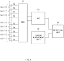
- the battery cell diagnostic device may be configured of a voltage measurement unit 10, a current measurement unit 20, and a detection unit 30.
- the voltage measurement unit 10 is a component for measuring a voltage between both ends of each unit cell of a battery pack (namely, each unit cell of a plurality of unit cells connected in series in a battery module).
- the voltage measurement unit 10 may be configured, for at least the plurality of unit cells Ce11 1 to Cell 8 connected in series, of: a multiplexer 11 of which measurement terminals T1 to T9 are respectively connected to lead units of the unit cells and lead units of both outermost unit cells, and output measurement voltages from the measurement terminals of the both ends of one unit cell according to preset measurement conditions; and an ADC 13 for analog-to-digitally converting the measurement voltages from the multiplexer 11.
- the preset measurement conditions may be set variously according to the measurement environment, and, for example, set to measure in order from Cell 1 to Cell 8 at a predetermined period.
- the current measurement unit 20 is a component for measuring a current of the battery pack.
- the current measurement unit 20 may be connected in series on a charging or discharging line, and measure a current amount when the battery pack is in a charged or discharged state. In this way, the technique for measuring a current amount of a battery pack in a charges or discharged state is well-known, and thus a detailed description thereabout will be omitted.
- the detection unit 30 compares a first voltage measured for each unit cell when the battery pack is in an open circuit voltage state with a second voltage measured for each unit cell according to a predetermined current flowing through the battery pack, when the battery pack is in a charged or discharged state, and detects whether the unit cell is abnormal. In other words, the detection unit 30 compares, for each unit cell, a voltage when the battery pack is in an open circuit voltage state with a voltage in a charged or discharged state to determine whether to the unit cell is abnormal.
- the first voltage in the open circuit voltage state is a reference value for comparison and may be measured once to be repeatedly used.
- the battery cell diagnostic device may further include a memory (not shown) for storing at least one among the first voltage and the second voltage.
- the detection unit 30 determines, for each unit cell, whether a voltage difference between the first voltage and the second voltage exceeds a predetermined reference value to detect whether the unit cell is abnormal. According to this, when an abnormality of the unit cell is detected, the detection unit 30 may determine that resistance equal to or greater than a predetermined reference value is present in a part of the lead units of both ends of the unit cell. Furthermore, since the present invention determines an increase in resistance component through a voltage between both ends of each unit cell, even when not only the resistance present between the lead units of the both ends but internal resistance of each unit cell also increases, the abnormality of the unit cell may be detected. Accordingly, the abnormality in the resistance of the battery cell may be comprehensively diagnosed. In addition, as in the present invention, comparing voltage differences under a predetermined condition for each unit cell to detect the abnormality enables more accurate diagnosis than comparing voltage differences between unit cells. The reason is that the voltage difference in manufacturing design may preexist between unit cells.
- FIG. 4 is an exemplary diagram for explaining a case in which no lead resistance is present in the battery cell upon diagnosing the battery cell
- FIG. 5 is an exemplary diagram for explaining a case in which the lead resistance is present in the battery cell upon diagnosing the battery cell.
- each unit cell of a battery pack is designed to have a voltage of 3V in FIGS. 4 and 5 .
- the voltage of each unit cell which is measured by the multiplexer 11 and the ADC 12 of the voltage measurement unit may be approximately, for example, 3 V.
- the battery discharging is performed to flow a current to the battery cell.
- the discharge current measured by the current measurement unit 20 is 100A
- the measurement voltage of each unit cell shows approximately 2.9 V.
- the voltage difference between the voltage measured in the open circuit voltage state for each unit cell and the voltage measured in a state of 100A discharging becomes approximately 0.1 V.
- a resistance value which is a magnitude not negligible as lead resistance
- the voltage of each unit cell which is measured by the multiplexer 11 and the ADC 13 of the voltage measurement unit is still approximately 3 V, when the battery pack is in the open circuit voltage state.
- the measurement voltage of each unit cell shows approximately 2.9 V when the discharge current measured by the current measurement unit 20 is 100A for unit cells Cell1 to Cell 4 and Cell 6 to Cell 8, but unit cell, Cell 5 shows approximately 3.9 V (namely, cell voltage 2.9 V + lead resistance-applied voltage 1 V).
- the detection unit 30 may determine that the resistance is present in the lead unit of unit cell, Cell 5.
- the detection unit 30 may generate a notification signal for the corresponding unit cell.
- the battery management system limits a charging/discharging operation of the battery upon generating the notification signal or transmits the notification signal to the upper layer controller or a manager's terminal to display a warning.
- an additional accident may be prevented in advance by rapidly treating the abnormality.
- the resistance of the lead unit of the unit cell may be rapidly diagnosed upon charging and discharging, and thus the stability of the battery may be raised.
- FIG. 6 is a flowchart showing a battery cell diagnostic method according to an embodiment of the present invention.
- the battery cell diagnostic method measures a voltage (namely, a first voltage) for each unit cell of the battery pack by means of a voltage measurement unit, when the batty pack is in an open circuit voltage state (operation S10).
- a voltage namely, a second voltage
- a voltage is measured for each unit cell according to a predetermined current flowing through the battery pack by means of the current measurement unit and the voltage measurement unit (operation S20).
- the first voltage measured in operation S10 and the second voltage measured in operation S20 are compared for each unit cell (operation S30). For example, it is determined whether a voltage difference between the first voltage and the second voltage exceeds a predetermined reference value.
- operation S30 when the voltage difference between the first voltage and the second voltage exceeds the predetermined reference value (Yes), the detection unit determines that the corresponding unit cell is abnormal (operation S31).
- the detection unit determines that the corresponding unit cell is abnormal (operation S31).
- the detection unit determines that the corresponding unit cell is normal (namely, no abnormality) (operation S33).
- the detection unit determines whether the abnormality determination is performed on all the unit cells (operation S40).
- the procedure moves to operation S30 again and determines whether the next cell is abnormal.
- the monitoring procedure ends.
- the determination unit may move to operation S10 or S20 according to a preset period and repeat a subsequent procedure.
- the battery cell diagnostic method may further include an operation for generating a notification signal for a unit cell, when an abnormality in the corresponding unit cell is detected.
- FIG. 7 is a flowchart showing a battery cell diagnostic processing method according to an embodiment of the present invention.
- the battery cell of the battery pack is monitored (operation S110). For example, as shown in FIG. 6 , whether there is an abnormality is determined for all the unit cells of the battery pack through operations S10 to S40. Then, it is determined whether the abnormality is detected in at least one among the plurality of unit cells of the battery pack (operation S120). In operation S120, when the abnormality of the unit cell is not detected (No), the procedure moves to operation S110 again and the battery cell is diagnosed.
- the detection unit when the abnormality is detected in the unit cell (Yes), the detection unit generates a excessive voltage signal (namely, a cell contact resistance increase signal or a cell lead unit resistance increase signal) as a notification signal for the unit cell from which the abnormality is detected, and transmits the notification signal to the upper layer controller (e.g., an MCU of the battery management system) or a preset manager's terminal (operation S130). Then, the battery charging/discharging current is limited by the upper layer controller (e.g., the battery management system, etc.), and a warning signal is displayed through a separate output unit (operation S150).
- a separate output unit e.g., a separate output unit
- the occurrence of the abnormality due to the increase in resistance of the unit cell may be rapidly treated and an additional accident may be prevented in advance.
- the present invention may be implemented with a battery pack.
- the battery pack may be configured to include: a battery module including at least a plurality of unit cells connected in series; and a battery management system for controlling charging and discharging of the battery module, wherein the battery management system includes: a voltage measurement unit which measure a voltage between both ends of each of the unit cells; a current measurement unit which measures a current of the battery module; and a detection unit which compares a first voltage measured for each of the unit cells when the battery module is in an open circuit voltage state, and a second voltage measured for each of the unit cells according to a predetermined current flowing through the battery module when the battery module is in a charging or discharging state, and detects whether the unit cell is abnormal.
- the resistance in the lead unit of the unit cell may be rapidly monitored upon charging and discharging, and thus the stability of the battery may be raised.
- FIG. 8 is a block diagram representing a hardware configuration of a battery management system (BMS) according to an embodiment of the present invention.
- the battery management system 300 may include: a microcontroller (MCU) 310 for controlling various kinds of processes and each component; a memory 320 in which an operation system program, various kinds of programs (e.g., a battery pack abnormality diagnostic program, a battery pack temperature estimation program), and the like are stored; an input and output interface 330 for providing an input interface and an output interface with the battery cell module and/or switching unit (e.g., a semiconductor switching element); and a communication interface 340 communicable with the outside (e.g., an upper layer controller) through a wired or wireless communication network.
- a computer program according to the present invention may be recorded in the memory 320 and processed by the microcontroller 310, and thus may be implemented as modules respectively performing functional blocks illustrated in FIGS. 2 and 3 .
Landscapes
- General Physics & Mathematics (AREA)
- Physics & Mathematics (AREA)
- Engineering & Computer Science (AREA)
- General Chemical & Material Sciences (AREA)
- Chemical Kinetics & Catalysis (AREA)
- Electrochemistry (AREA)
- Chemical & Material Sciences (AREA)
- Manufacturing & Machinery (AREA)
- Power Engineering (AREA)
- Microelectronics & Electronic Packaging (AREA)
- Secondary Cells (AREA)
- Charge And Discharge Circuits For Batteries Or The Like (AREA)
- Tests Of Electric Status Of Batteries (AREA)
Abstract
Description
- This application claims the benefit of
Korean Patent Application No. 10-2019-0052154, filed on May 03, 2019 - The present invention relates to a device and method for diagnosing an increase in resistance of a lead unit of a battery cell.
- Typically, when a plurality of unit cells are connected in series and/or parallel so as to form a high voltage battery, the resistance of lead units of both ends of a unit cell, which are contact units, increases due to corrosion or poor contact, etc., of the lead units.
- When the resistance of the lead units increases in this way, degradation of the corresponding unit cell becomes accelerated due to heating of a part having the increased resistance upon charging and discharging the battery. In addition, due to a voltage applied to the corresponding resistance part, a measurement error occurs upon measuring a cell voltage. Furthermore, there is also an issue that the heating leads to ignition of the battery.
- An aspect of the present invention provides a battery cell diagnostic device and method for rapidly diagnosing resistance of a lead unit of a unit cell upon charging and discharging a battery to raise stability of the battery, when the battery includes at least a plurality of unit cells connected in series.
- According to an aspect of the present invention, there is provided a battery cell diagnostic device including: a voltage measurement unit configured to measure a voltage between both ends of each unit cell of a battery pack; a current measurement unit configured to measure a current of the battery pack; and a detection unit configured to compare a first voltage measured for each of the unit cells when the battery pack is in an open circuit voltage state with a second voltage measured for each of the unit cells according to a predetermined current flowing through the battery pack, when the battery pack is in a charged or discharged state, and detect whether each of the unit cells is abnormal.
- The voltage measurement unit may include: a multiplexer of which measurement terminals are respectively connected to lead units between the unit cells and lead units of both outermost unit cells with respect to at least a plurality of the unit cells connected in series, and which outputs a measurement voltage from measurement terminals of both ends of one unit cell according to a preset measurement condition; and an analog-to-digital converter (ADC) configured to analog-to-digitally converts the measurement voltage output from the multiplexer.
- For each of the unit cells, the detection unit may determine whether a voltage difference between the first voltage and the second voltage exceeds a predetermined reference value to detect whether the unit cell is abnormal. In response to the abnormality of the unit cell being detected, the detection unit may determine that resistance equal to or greater than a predetermined reference value is present in a part of the lead units of both ends of the unit cell.
- As an example, in response to the abnormality in the unit cell being detected, the detection unit may generate a notification signal for the unit cell.
- In addition, the battery cell diagnostic device according to an embodiment of the present invention may further include a memory configured to store at least one between the first voltage and the second voltage.
- According to another aspect of the present invention, there is provided a battery cell diagnostic method including: a first voltage measurement step in which when a battery pack is in an open circuit voltage state, a voltage is measured for each unit cell of the battery pack; a second voltage measurement step in which, when the battery pack is in a charging or discharging state, a voltage is measured for each unit cell according to a predetermined current flowing through the battery pack; and a step for comparing, for each unit cell, a voltage measured in the first voltage measurement step and a voltage measured in the second voltage measurement step, and detecting whether the unit cell is abnormal.
- In the detecting step, whether the unit cell is abnormal may be detected by determining that a voltage difference between the first voltage and the second voltage exceeds a predetermined reference value. As an example, in response to the abnormality of the unit cell being detected, it may be determined that resistance equal to or greater than a predetermined reference value is present in a part of the lead units of both ends of the unit cell.
- The battery cell diagnostic method according to an embodiment of the present invention may further include a step for generating a notification signal for the unit cell, in response to the abnormality of the unit cell being detected.
- In addition, the present invention may be implemented with a battery pack. According to another aspect of the present invention, there is provided a battery pack including: a battery module including at least a plurality of unit cells connected in series; and a battery management system configured to control charging and discharging the battery module, wherein the battery management system may include: a voltage measurement unit configured to measure a voltage between both ends of each of the unit cells; a current measurement unit configured to measure a current of the battery module; and a detection unit configured to compare a first voltage measured for each of the unit cells when the battery pack is in an open circuit voltage state with a second voltage measured for each of the unit cells according to a predetermined current flowing through the battery pack, when the battery pack is in a charging or discharging state, and to detect whether each of the unit cells is abnormal.
- According to the present invention, resistance of a lead unit of a unit cell upon charging and discharging a battery may be rapidly diagnosed to raise the stability of the battery.
- The effects of the present invention will be additionally descried according to embodiments of the present invention.
-
-
FIG. 1 is a block diagram schematically representing the configuration of a battery pack; -
FIG. 2 is a block diagram for explaining the configuration of a battery cell diagnostic device; -
FIG. 3 is an exemplary diagram specifically representing the configuration of a voltage measurement unit ofFIG. 2 ; -
FIG. 4 is an exemplary diagram for explaining a case in which no lead resistance is present in a battery cell upon diagnosing the battery cell; -
FIG. 5 is an exemplary diagram for explaining a case in which the lead resistance is present in the battery cell upon diagnosing the battery cell; -
FIG. 6 is a flowchart representing a battery cell diagnostic method according to an embodiment of the present invention; -
FIG. 7 is a flowchart representing a battery cell diagnosis processing method according to an embodiment of the present invention; and -
FIG. 8 is a block diagram representing a hardware configuration of a battery management system (BMS) according to an embodiment of the present invention. - Hereinafter, various embodiments of the present invention will be disclosed with reference to the accompanying drawings. However, the description is not intended to limit the present invention to particular embodiments, and it should be construed as including various modifications, equivalents, and/or alternatives according to the embodiments of the present invention. In regard to the description of the drawings, like reference numerals refer to like elements.
- Terms defined in the present invention are used for only describing a specific exemplary embodiment and may not have an intention to limit the scope of other exemplary embodiments. As used herein, the singular forms "a," "an" and "the" are intended to include the plural forms as well, unless the context clearly indicates otherwise. Unless differently defined, entire terms including a technical term and a scientific term used here have the same meaning as a meaning that may be generally understood by a person of common skill in the art. The terms defined in a generally used dictionary should be interpreted as having meanings that are the same as or similar with the contextual meanings of the relevant technology and should not be interpreted as having ideal or exaggerated meanings unless they are clearly defined in the various exemplary embodiments. In some case, terms defined in the present invention cannot be analyzed to exclude the present exemplary embodiments.
- In addition, in describing elements of embodiments of the present invention, terms such as first, second, A, B, (a), and (b) may be used. Such terms are used only for distinguishing an element from another element, but do not limit the substance of the element, sequence or order. It should be noted that if it is described in the specification that one element is "connected," "coupled" or "joined" to another element, a third component may be "connected," "coupled," and "joined" between the one element and the other component, although the one element may be directly connected, coupled or joined to the other element.
- The configuration of a battery pack will be described with reference to
FIG. 1. FIG. 1 is a block diagram schematically representing the configuration of the battery pack. - As shown in
FIG. 1 , a battery pack B is configured of one or more battery cells, and includes abattery module 1 that is chargeable and dischargeable, aswitching unit 2 connected in series with an anode side or a cathode side of thebattery module 1 and for controlling a charging/discharging current flow of thebattery module 1, and a battery management system 3 (hereinafter, BMS) for monitoring a voltage, a current, a temperature, or the like of the battery pack B, and controlling and managing the battery pack B so as to prevent overcharging, overdischarging, and the like. - Here, the
switching unit 2 is a mechanical switching element or a semiconductor switching element for controlling a current flow with respect to charging or discharging of thebattery module 1, and, for example, at least one mechanical relay or a MOSFET may be employed. - In addition, the
BMS 3 may be connected to thebattery module 1 to receive data with respect to the voltage, current, or temperature so as to monitor the voltage, current, temperature, or the like of the battery pack B. In addition, for example, when theswitching unit 2 is a semiconductor switching element, a voltage and a current of the gate, source, or drain terminal of the semiconductor switching element may be measured or calculated. In addition, the current, voltage, temperature, or the like of thebattery module 1 may be measured using various types ofsensors 4 provided adjacently to the semiconductor switching element. TheBMS 3 may be an interface for receiving values obtained by measuring various parameters, and include a plurality of terminals, and a circuit or the like connected to the terminals and for processing the received values. - In addition, the
BMS 3 may control turning ON/OFF of theswitching unit 2, and be connected to thebattery module 1 to monitor the state of thebattery module 1. - In addition, the BMS 3 may be connected to an
upper layer controller 7. TheBMS 3 may transmit information about a state of and a control for the battery to theupper layer controller 7, or control an operation of the battery pack B on the basis of a control signal applied from theupper layer controller 7. TheBMS 3 may transmit and receive various types of signals and data in a wired and/or wireless manner with theupper layer controller 7. Here, the battery pack B may be, for example, a vehicle battery pack, and theupper layer controller 7 may be a microcontroller MCU of a vehicle system. Alternatively, the battery pack B may be a battery pack of an energy storage system (ESS), but is not limited thereto. - A battery cell diagnostic device according to an embodiment of the present invention may be a component between the
battery module 1 and thebattery management system 3, or a part of thebattery management system 3. - The battery cell diagnostic device according to an embodiment of the present invention will be described with reference to
FIGS. 2 and3 .FIG. 2 is a block diagram for explaining the configuration of the battery cell diagnostic device;FIG. 3 is an exemplary diagram specifically representing the configuration of a voltage measurement unit ofFIG. 2 . - As illustrated in
FIG. 2 , the battery cell diagnostic device according to an embodiment of the present invention may be configured of avoltage measurement unit 10, acurrent measurement unit 20, and adetection unit 30. - The
voltage measurement unit 10 is a component for measuring a voltage between both ends of each unit cell of a battery pack (namely, each unit cell of a plurality of unit cells connected in series in a battery module). - For example, as illustrated in
FIG. 3 , thevoltage measurement unit 10 may be configured, for at least the plurality ofunit cells Ce11 1 toCell 8 connected in series, of: amultiplexer 11 of which measurement terminals T1 to T9 are respectively connected to lead units of the unit cells and lead units of both outermost unit cells, and output measurement voltages from the measurement terminals of the both ends of one unit cell according to preset measurement conditions; and anADC 13 for analog-to-digitally converting the measurement voltages from themultiplexer 11. Here, the preset measurement conditions may be set variously according to the measurement environment, and, for example, set to measure in order fromCell 1 toCell 8 at a predetermined period. - The
current measurement unit 20 is a component for measuring a current of the battery pack. For example, thecurrent measurement unit 20 may be connected in series on a charging or discharging line, and measure a current amount when the battery pack is in a charged or discharged state. In this way, the technique for measuring a current amount of a battery pack in a charges or discharged state is well-known, and thus a detailed description thereabout will be omitted. - The
detection unit 30 compares a first voltage measured for each unit cell when the battery pack is in an open circuit voltage state with a second voltage measured for each unit cell according to a predetermined current flowing through the battery pack, when the battery pack is in a charged or discharged state, and detects whether the unit cell is abnormal. In other words, thedetection unit 30 compares, for each unit cell, a voltage when the battery pack is in an open circuit voltage state with a voltage in a charged or discharged state to determine whether to the unit cell is abnormal. Here, the first voltage in the open circuit voltage state is a reference value for comparison and may be measured once to be repeatedly used. To this end, the battery cell diagnostic device according to an embodiment of the present invention may further include a memory (not shown) for storing at least one among the first voltage and the second voltage. - The
detection unit 30 determines, for each unit cell, whether a voltage difference between the first voltage and the second voltage exceeds a predetermined reference value to detect whether the unit cell is abnormal. According to this, when an abnormality of the unit cell is detected, thedetection unit 30 may determine that resistance equal to or greater than a predetermined reference value is present in a part of the lead units of both ends of the unit cell. Furthermore, since the present invention determines an increase in resistance component through a voltage between both ends of each unit cell, even when not only the resistance present between the lead units of the both ends but internal resistance of each unit cell also increases, the abnormality of the unit cell may be detected. Accordingly, the abnormality in the resistance of the battery cell may be comprehensively diagnosed. In addition, as in the present invention, comparing voltage differences under a predetermined condition for each unit cell to detect the abnormality enables more accurate diagnosis than comparing voltage differences between unit cells. The reason is that the voltage difference in manufacturing design may preexist between unit cells. - As an embodiment, a diagnostic process by the battery cell diagnostic device will be described with reference to
FIGS. 4 and5 .FIG. 4 is an exemplary diagram for explaining a case in which no lead resistance is present in the battery cell upon diagnosing the battery cell, andFIG. 5 is an exemplary diagram for explaining a case in which the lead resistance is present in the battery cell upon diagnosing the battery cell. - First, it is assumed that each unit cell of a battery pack is designed to have a voltage of 3V in
FIGS. 4 and5 . As inFIG. 4 , when the battery cell is assumed to scarcely have lead resistance, in case where there is no charging and discharging current, namely, the battery pack is in an open circuit voltage state, the voltage of each unit cell, which is measured by themultiplexer 11 and the ADC 12 of the voltage measurement unit may be approximately, for example, 3 V. Then, the battery discharging is performed to flow a current to the battery cell. Here, for example, the discharge current measured by thecurrent measurement unit 20 is 100A, and the measurement voltage of each unit cell shows approximately 2.9 V. In this case, the voltage difference between the voltage measured in the open circuit voltage state for each unit cell and the voltage measured in a state of 100A discharging becomes approximately 0.1 V. - However, as shown in
FIG. 5 , when a resistance value, which is a magnitude not negligible as lead resistance, is assumed to be about, for example, 10 mQ in, for example, a unit cell,Cell 5, the voltage of each unit cell, which is measured by themultiplexer 11 and theADC 13 of the voltage measurement unit is still approximately 3 V, when the battery pack is in the open circuit voltage state. However, when battery discharging is performed thereafter and a current flows to the battery cell, the measurement voltage of each unit cell shows approximately 2.9 V when the discharge current measured by thecurrent measurement unit 20 is 100A for unit cells Cell1 toCell 4 andCell 6 toCell 8, but unit cell,Cell 5 shows approximately 3.9 V (namely, cell voltage 2.9 V + lead resistance-applied voltage 1 V). Accordingly, when comparing voltage differences between a voltage for each unit cell, which is measured in the open circuit voltage state, and a voltage measured upon 100A discharging, the voltage difference is 0.1 V forunit cells Cell 1 toCell 4 andCell 6 toCell 8, but is -0.9 V for unit cell,Cell 5. Accordingly, thedetection unit 30 may determine that the resistance is present in the lead unit of unit cell,Cell 5. - In addition, when the abnormality is detected for a unit cell, the
detection unit 30 may generate a notification signal for the corresponding unit cell. Thereby, the battery management system, for example, limits a charging/discharging operation of the battery upon generating the notification signal or transmits the notification signal to the upper layer controller or a manager's terminal to display a warning. Thus, when the abnormality occurs due to the resistance increase in the unit cell, an additional accident may be prevented in advance by rapidly treating the abnormality. - In this way, according to the present invention, the resistance of the lead unit of the unit cell may be rapidly diagnosed upon charging and discharging, and thus the stability of the battery may be raised.
- Next, the battery cell diagnostic method according to an embodiment of the present invention will be described with reference to
FIG 6. FIG. 6 is a flowchart showing a battery cell diagnostic method according to an embodiment of the present invention. - As shown in
FIG. 6 , the battery cell diagnostic method according to an embodiment of the present invention measures a voltage (namely, a first voltage) for each unit cell of the battery pack by means of a voltage measurement unit, when the batty pack is in an open circuit voltage state (operation S10). Next, when the battery pack is in a charged or discharged state, a voltage (namely, a second voltage) is measured for each unit cell according to a predetermined current flowing through the battery pack by means of the current measurement unit and the voltage measurement unit (operation S20). Then, the first voltage measured in operation S10 and the second voltage measured in operation S20 are compared for each unit cell (operation S30). For example, it is determined whether a voltage difference between the first voltage and the second voltage exceeds a predetermined reference value. In operation S30, when the voltage difference between the first voltage and the second voltage exceeds the predetermined reference value (Yes), the detection unit determines that the corresponding unit cell is abnormal (operation S31). When the abnormality of the unit cell is detected in this way, the resistance equal to or greater than a predetermined reference value may be determined to be present in a part of the lead units of both ends of the unit cell. In operation S30, when the voltage difference between the first voltage and the second voltage does not exceed the predetermined reference value (No), the detection unit determines that the corresponding unit cell is normal (namely, no abnormality) (operation S33). Next, the detection unit determines whether the abnormality determination is performed on all the unit cells (operation S40). When the abnormality determination is not completed for all the unit cells in operation 40 (No), the procedure moves to operation S30 again and determines whether the next cell is abnormal. When the abnormality determination is completed for all the unit cells in operation 40 (Yes), the monitoring procedure ends. Alternatively, when the abnormality determination is completed for all the unit cells in operation 40 (Yes), the determination unit may move to operation S10 or S20 according to a preset period and repeat a subsequent procedure. - In addition, the battery cell diagnostic method according to an embodiment of the present invention may further include an operation for generating a notification signal for a unit cell, when an abnormality in the corresponding unit cell is detected.
- As an embodiment, the procedure of the battery cell diagnostic processing method will be described with reference to
FIG. 7. FIG. 7 is a flowchart showing a battery cell diagnostic processing method according to an embodiment of the present invention. - First, the battery cell of the battery pack is monitored (operation S110). For example, as shown in
FIG. 6 , whether there is an abnormality is determined for all the unit cells of the battery pack through operations S10 to S40. Then, it is determined whether the abnormality is detected in at least one among the plurality of unit cells of the battery pack (operation S120). In operation S120, when the abnormality of the unit cell is not detected (No), the procedure moves to operation S110 again and the battery cell is diagnosed. In operation S120, when the abnormality is detected in the unit cell (Yes), the detection unit generates a excessive voltage signal (namely, a cell contact resistance increase signal or a cell lead unit resistance increase signal) as a notification signal for the unit cell from which the abnormality is detected, and transmits the notification signal to the upper layer controller (e.g., an MCU of the battery management system) or a preset manager's terminal (operation S130). Then, the battery charging/discharging current is limited by the upper layer controller (e.g., the battery management system, etc.), and a warning signal is displayed through a separate output unit (operation S150). - Accordingly, the occurrence of the abnormality due to the increase in resistance of the unit cell may be rapidly treated and an additional accident may be prevented in advance.
- Furthermore, the present invention may be implemented with a battery pack. The battery pack according to an embodiment of the present invention may be configured to include: a battery module including at least a plurality of unit cells connected in series; and a battery management system for controlling charging and discharging of the battery module, wherein the battery management system includes: a voltage measurement unit which measure a voltage between both ends of each of the unit cells; a current measurement unit which measures a current of the battery module; and a detection unit which compares a first voltage measured for each of the unit cells when the battery module is in an open circuit voltage state, and a second voltage measured for each of the unit cells according to a predetermined current flowing through the battery module when the battery module is in a charging or discharging state, and detects whether the unit cell is abnormal. In this way, according to the present invention, the resistance in the lead unit of the unit cell may be rapidly monitored upon charging and discharging, and thus the stability of the battery may be raised.
- On the other hand, the battery management system BMS of the battery pack according to the present invention may be represented as in
FIG. 7 .FIG. 8 is a block diagram representing a hardware configuration of a battery management system (BMS) according to an embodiment of the present invention. - As illustrated in
FIG. 8 , thebattery management system 300 may include: a microcontroller (MCU) 310 for controlling various kinds of processes and each component; amemory 320 in which an operation system program, various kinds of programs (e.g., a battery pack abnormality diagnostic program, a battery pack temperature estimation program), and the like are stored; an input andoutput interface 330 for providing an input interface and an output interface with the battery cell module and/or switching unit (e.g., a semiconductor switching element); and acommunication interface 340 communicable with the outside (e.g., an upper layer controller) through a wired or wireless communication network. In this way, a computer program according to the present invention may be recorded in thememory 320 and processed by themicrocontroller 310, and thus may be implemented as modules respectively performing functional blocks illustrated inFIGS. 2 and3 . - Although the present invention has been described in conjunction with the limited embodiments and drawings, the present invention is not limited thereto. It will be appreciated that various modifications and changes can be made by those skilled in the art without departing from the scope and equivalents of the appended claims.
Claims (11)
- A battery cell diagnostic device comprising:a voltage measurement unit configured to measure a voltage between both ends of each unit cell of a battery pack;a current measurement unit configured to measure a current of the battery pack; anda detection unit configured to compare a first voltage measured for each of the unit cells when the battery pack is in an open circuit voltage state with a second voltage measured for each of the unit cells according to a predetermined current flowing through the battery pack, when the battery pack is in a charged or discharged state, and detect whether each of the unit cells is abnormal.
- The battery cell diagnostic device of claim 1, wherein the voltage measurement unit comprises:a multiplexer of which measurement terminals are respectively connected to lead units between the unit cells and lead units of both outermost unit cells with respect to at least a plurality of the unit cells connected in series, and which outputs a measurement voltage from measurement terminals of both ends of one unit cell according to a preset measurement condition; andan analog-to-digital converter (ADC) configured to analog-to-digitally converts the measurement voltage output from the multiplexer.
- The battery cell diagnostic device of claim 2, wherein, for each of the unit cells, the detection unit determines whether a voltage difference between the first voltage and the second voltage exceeds a predetermined reference value to detect whether the unit cell is abnormal.
- The battery cell diagnostic device of claim 3, wherein, in response to abnormality of the unit cell being detected, the detection unit determines that resistance equal to or greater than a predetermined reference value is present in a part of the lead units of both ends of the unit cell.
- The battery cell diagnostic device of claim 1, further comprising:
a memory configured to store at least one of the first voltage and the second voltage. - The battery cell diagnostic device of claim 1, wherein, in response to the abnormality of the unit cell being detected, the detection unit generates a notification signal for the unit cell.
- A battery cell diagnostic method comprising:a first voltage measurement step in which when a battery pack is in an open circuit voltage state, a voltage is measured for each unit cell of the battery pack;a second voltage measurement step in which, when the battery pack is in a charging or discharging state, a voltage is measured for each unit cell according to a predetermined current flowing through the battery pack; anda step for comparing, for each unit cell, a voltage measured in the first voltage measurement step and a voltage measured in the second voltage measurement step, and detecting whether the unit cell is abnormal.
- The battery cell diagnostic method of claim 7, wherein, in the detecting step, whether the unit cell is abnormal is detected by determining that a voltage difference between the first voltage and the second voltage exceeds a predetermined reference value.
- The battery cell diagnostic method of claim 8, wherein, in response to the abnormality of the unit cell being detected, it is determined that resistance equal to or greater than a predetermined reference value is present in a part of the lead units of both ends of the unit cell.
- The battery cell diagnostic method of claim 7, further comprising:
a step for generating a notification signal for the unit cell, in response to the abnormality of the unit cell is detected. - A battery pack comprising:a battery module comprising at least a plurality of unit cells connected in series; anda battery management system configured to control charging and discharging the battery module,wherein the battery management system comprises:a voltage measurement unit configured to measure a voltage between both ends of each of the unit cells;a current measurement unit configured to measure a current of the battery module; anda detection unit configured to compare a first voltage measured for each of the unit cells when the battery pack is in an open circuit voltage state with a second voltage measured for each of the unit cells according to a predetermined current flowing through the battery pack, when the battery pack is in a charging or discharging state, and to detect whether each of the unit cells is abnormal.
Applications Claiming Priority (2)
| Application Number | Priority Date | Filing Date | Title |
|---|---|---|---|
| KR1020190052154A KR102819970B1 (en) | 2019-05-03 | 2019-05-03 | Apparatus and method for diagnosing battery cell |
| PCT/KR2020/005425 WO2020226308A1 (en) | 2019-05-03 | 2020-04-24 | Apparatus and method for diagnosing battery cell |
Publications (3)
| Publication Number | Publication Date |
|---|---|
| EP3951410A1 true EP3951410A1 (en) | 2022-02-09 |
| EP3951410A4 EP3951410A4 (en) | 2022-06-01 |
| EP3951410B1 EP3951410B1 (en) | 2025-12-17 |
Family
ID=73051293
Family Applications (1)
| Application Number | Title | Priority Date | Filing Date |
|---|---|---|---|
| EP20802564.3A Active EP3951410B1 (en) | 2019-05-03 | 2020-04-24 | Battery cell diagnostic device and method |
Country Status (7)
| Country | Link |
|---|---|
| US (1) | US11796605B2 (en) |
| EP (1) | EP3951410B1 (en) |
| JP (1) | JP7732638B2 (en) |
| KR (1) | KR102819970B1 (en) |
| CN (1) | CN113748353B (en) |
| ES (1) | ES3061086T3 (en) |
| WO (1) | WO2020226308A1 (en) |
Families Citing this family (6)
| Publication number | Priority date | Publication date | Assignee | Title |
|---|---|---|---|---|
| CN121114775A (en) * | 2020-11-27 | 2025-12-12 | 株式会社Lg新能源 | Battery diagnostic devices, battery diagnostic methods, battery packs and vehicles |
| CN114487884A (en) * | 2022-01-17 | 2022-05-13 | 阳光储能技术有限公司 | Battery detection method and device, battery system and electronic equipment |
| KR102796713B1 (en) | 2023-04-06 | 2025-04-21 | (주)에어포인트 | The System Of Diagnosing Battery Cells In Electric Vehicle |
| KR102796711B1 (en) * | 2023-04-06 | 2025-04-21 | (주)에어포인트 | The System Of Diagnosing Battery Cells Using Boards Manufactured By LDCMOS Process |
| KR102914898B1 (en) * | 2023-08-17 | 2026-01-19 | 범한유니솔루션 주식회사 | Methods for inspecting battery cell joints |
| EP4675286A1 (en) * | 2024-07-05 | 2026-01-07 | Volvo Truck Corporation | Method and computer system for diagnosing an electrical connection within an electrical energy storage pack |
Family Cites Families (32)
| Publication number | Priority date | Publication date | Assignee | Title |
|---|---|---|---|---|
| JP2000215923A (en) | 1999-01-25 | 2000-08-04 | Matsushita Electric Ind Co Ltd | Battery deterioration judgment device |
| JP3988324B2 (en) | 1999-07-02 | 2007-10-10 | 株式会社デンソー | Abnormality determination apparatus for assembled battery and abnormality determination method for assembled battery |
| JP3939071B2 (en) | 2000-03-30 | 2007-06-27 | 三洋電機株式会社 | Inspection method and connection circuit for circuits connected to multiple batteries |
| JP3709785B2 (en) | 2000-12-01 | 2005-10-26 | 日産自動車株式会社 | Diagnostic device for battery pack |
| JP2003070161A (en) * | 2001-08-22 | 2003-03-07 | Osaka Gas Co Ltd | Power supply |
| JP2004014205A (en) | 2002-06-05 | 2004-01-15 | Nissan Motor Co Ltd | Battery abnormal deterioration detection device |
| JP4606846B2 (en) * | 2004-11-12 | 2011-01-05 | パナソニック株式会社 | Battery monitoring device |
| JP4799941B2 (en) * | 2005-07-20 | 2011-10-26 | 株式会社オートネットワーク技術研究所 | Battery state management device |
| KR100694486B1 (en) | 2006-06-09 | 2007-03-14 | (주) 피에스디테크 | Terminal block loosening detection device and detection method |
| JP5349021B2 (en) | 2008-11-26 | 2013-11-20 | 三洋電機株式会社 | Battery system |
| JP2009103706A (en) * | 2008-12-05 | 2009-05-14 | Shin Kobe Electric Mach Co Ltd | Battery voltage detection line inspection method, inspection circuit, and battery module |
| JP4696291B2 (en) | 2009-06-04 | 2011-06-08 | 三菱自動車工業株式会社 | Secondary battery abnormality detection device |
| US9246337B2 (en) | 2010-04-23 | 2016-01-26 | Hitachi, Ltd. | Battery pack and battery pack controller |
| CN103314477B (en) | 2010-12-28 | 2016-04-13 | 株式会社Lg化学 | Apparatus and method for controlling a battery pack system |
| CN103308860A (en) | 2012-03-15 | 2013-09-18 | 凹凸电子(武汉)有限公司 | Battery fault detection method, battery fault detection device and battery management system |
| CN105637671B (en) | 2013-10-16 | 2018-01-19 | 英属盖曼群岛商立凯绿能移动科技股份有限公司 | Device for confirming locking state of electrode contact of electric vehicle and device for confirming locking state of battery module electrode |
| JP6379552B2 (en) * | 2014-03-20 | 2018-08-29 | 三洋電機株式会社 | Power storage system with anomaly detector |
| KR20160012695A (en) * | 2014-07-25 | 2016-02-03 | 에스케이이노베이션 주식회사 | Battery cell sensing apparatus and Controlling method thereof |
| JP6264231B2 (en) * | 2014-09-01 | 2018-01-24 | 株式会社デンソー | Battery monitoring device |
| CN104297689B (en) | 2014-09-04 | 2017-05-24 | 中兴通讯股份有限公司 | A method, device and electronic equipment for displaying battery power |
| CN104410111B (en) * | 2014-11-03 | 2017-03-29 | 惠州市亿能电子有限公司 | Voltage acquisition line impedence backoff algorithm on battery management system |
| JP6402597B2 (en) * | 2014-11-12 | 2018-10-10 | 株式会社Gsユアサ | Battery monitoring device, power storage device, and disconnection diagnosis method |
| KR20160091568A (en) * | 2015-01-26 | 2016-08-03 | 주식회사 엘지화학 | Battery Pack Comprising Control Unit Determining Abnormal State of Battery Units |
| KR20160123173A (en) | 2015-04-15 | 2016-10-25 | 삼성전자주식회사 | Apparatus and Method for determining connection status of busbar |
| CN106816905B (en) * | 2015-11-30 | 2019-09-13 | 比亚迪股份有限公司 | Electric vehicle and battery management system and fault detection method thereof |
| WO2017168964A1 (en) * | 2016-03-31 | 2017-10-05 | パナソニックIpマネジメント株式会社 | Battery module |
| KR102319241B1 (en) | 2017-01-03 | 2021-10-28 | 삼성에스디아이 주식회사 | Voltage detecting ic and battery management system including the same |
| DE102017201912A1 (en) * | 2017-02-07 | 2018-08-09 | Robert Bosch Gmbh | Battery system and method for measuring measurement voltages in a battery system |
| FR3070764B1 (en) * | 2017-09-04 | 2020-09-04 | Renault Sas | PROCESS FOR DETERMINING THE STATE OF AN ELECTRICAL LINE CONNECTING A BATTERY CELL OF ACCUMULATORS TO A CONTROL UNIT AND CORRESPONDING CONTROL UNIT |
| CN108469589B (en) * | 2018-02-08 | 2020-06-26 | 惠州市亿能电子有限公司 | Power battery pack connection abnormity judgment method |
| CN108957335B (en) * | 2018-05-21 | 2020-09-04 | 合肥工业大学 | SOC online estimation method of 2kW/10 kW.h all-vanadium redox flow battery |
| JP7289113B2 (en) * | 2018-07-25 | 2023-06-09 | パナソニックIpマネジメント株式会社 | Management device and power supply system |
-
2019
- 2019-05-03 KR KR1020190052154A patent/KR102819970B1/en active Active
-
2020
- 2020-04-24 CN CN202080030671.6A patent/CN113748353B/en active Active
- 2020-04-24 US US17/608,264 patent/US11796605B2/en active Active
- 2020-04-24 WO PCT/KR2020/005425 patent/WO2020226308A1/en not_active Ceased
- 2020-04-24 JP JP2021563606A patent/JP7732638B2/en active Active
- 2020-04-24 EP EP20802564.3A patent/EP3951410B1/en active Active
- 2020-04-24 ES ES20802564T patent/ES3061086T3/en active Active
Also Published As
| Publication number | Publication date |
|---|---|
| EP3951410B1 (en) | 2025-12-17 |
| CN113748353B (en) | 2024-10-25 |
| ES3061086T3 (en) | 2026-03-31 |
| JP7732638B2 (en) | 2025-09-02 |
| JP2022530488A (en) | 2022-06-29 |
| US20220214405A1 (en) | 2022-07-07 |
| US11796605B2 (en) | 2023-10-24 |
| EP3951410A4 (en) | 2022-06-01 |
| KR20200127638A (en) | 2020-11-11 |
| KR102819970B1 (en) | 2025-06-13 |
| CN113748353A (en) | 2021-12-03 |
| WO2020226308A1 (en) | 2020-11-12 |
Similar Documents
| Publication | Publication Date | Title |
|---|---|---|
| EP3951410B1 (en) | Battery cell diagnostic device and method | |
| EP3961233B1 (en) | Battery cell diagnosis device and method | |
| US12040458B2 (en) | Slave BMS inspection system and method | |
| EP3958006B1 (en) | Battery diagnosis apparatus and method | |
| US11815558B2 (en) | Apparatus and method for diagnosing abnormal degradated battery cell | |
| CN114514433B (en) | Device and method for diagnosing a battery | |
| US12360166B2 (en) | Battery diagnosis apparatus, battery pack, electric vehicle and battery diagnosis method | |
| US11846680B2 (en) | Battery resistance diagnosis device and method | |
| US9172265B2 (en) | Battery charger, voltage monitoring device and self-diagnosis method of reference voltage circuit | |
| EP2110679A1 (en) | Device and method for detecting abnormality of electric storage device | |
| KR102709601B1 (en) | Apparatus and method for diagnosing battery cell | |
| EP4016099B1 (en) | Apparatus and method for diagnosing battery | |
| US20260126496A1 (en) | Device for diagnosing a state of a battery and method thereof |
Legal Events
| Date | Code | Title | Description |
|---|---|---|---|
| STAA | Information on the status of an ep patent application or granted ep patent |
Free format text: STATUS: THE INTERNATIONAL PUBLICATION HAS BEEN MADE |
|
| PUAI | Public reference made under article 153(3) epc to a published international application that has entered the european phase |
Free format text: ORIGINAL CODE: 0009012 |
|
| STAA | Information on the status of an ep patent application or granted ep patent |
Free format text: STATUS: REQUEST FOR EXAMINATION WAS MADE |
|
| 17P | Request for examination filed |
Effective date: 20211027 |
|
| AK | Designated contracting states |
Kind code of ref document: A1 Designated state(s): AL AT BE BG CH CY CZ DE DK EE ES FI FR GB GR HR HU IE IS IT LI LT LU LV MC MK MT NL NO PL PT RO RS SE SI SK SM TR |
|
| RAP3 | Party data changed (applicant data changed or rights of an application transferred) |
Owner name: LG ENERGY SOLUTION, LTD. |
|
| A4 | Supplementary search report drawn up and despatched |
Effective date: 20220503 |
|
| RIC1 | Information provided on ipc code assigned before grant |
Ipc: G01R 19/165 20060101ALN20220426BHEP Ipc: G01R 31/392 20190101ALN20220426BHEP Ipc: G01R 31/3842 20190101ALN20220426BHEP Ipc: G01R 31/389 20190101ALI20220426BHEP Ipc: G01R 31/58 20200101ALI20220426BHEP Ipc: G01R 31/396 20190101AFI20220426BHEP |
|
| DAV | Request for validation of the european patent (deleted) | ||
| DAX | Request for extension of the european patent (deleted) | ||
| STAA | Information on the status of an ep patent application or granted ep patent |
Free format text: STATUS: EXAMINATION IS IN PROGRESS |
|
| 17Q | First examination report despatched |
Effective date: 20240321 |
|
| GRAP | Despatch of communication of intention to grant a patent |
Free format text: ORIGINAL CODE: EPIDOSNIGR1 |
|
| STAA | Information on the status of an ep patent application or granted ep patent |
Free format text: STATUS: GRANT OF PATENT IS INTENDED |
|
| RIC1 | Information provided on ipc code assigned before grant |
Ipc: G01R 31/396 20190101AFI20250814BHEP Ipc: G01R 31/58 20200101ALI20250814BHEP Ipc: G01R 31/389 20190101ALI20250814BHEP Ipc: H01M 10/42 20060101ALI20250814BHEP Ipc: H01M 10/48 20060101ALI20250814BHEP Ipc: G01R 31/3842 20190101ALN20250814BHEP Ipc: G01R 31/392 20190101ALN20250814BHEP Ipc: G01R 19/165 20060101ALN20250814BHEP |
|
| INTG | Intention to grant announced |
Effective date: 20250911 |
|
| GRAS | Grant fee paid |
Free format text: ORIGINAL CODE: EPIDOSNIGR3 |
|
| GRAA | (expected) grant |
Free format text: ORIGINAL CODE: 0009210 |
|
| STAA | Information on the status of an ep patent application or granted ep patent |
Free format text: STATUS: THE PATENT HAS BEEN GRANTED |
|
| P01 | Opt-out of the competence of the unified patent court (upc) registered |
Free format text: CASE NUMBER: UPC_APP_0011254_3951410/2025 Effective date: 20251028 |
|
| AK | Designated contracting states |
Kind code of ref document: B1 Designated state(s): AL AT BE BG CH CY CZ DE DK EE ES FI FR GB GR HR HU IE IS IT LI LT LU LV MC MK MT NL NO PL PT RO RS SE SI SK SM TR |
|
| REG | Reference to a national code |
Ref country code: CH Ref legal event code: F10 Free format text: ST27 STATUS EVENT CODE: U-0-0-F10-F00 (AS PROVIDED BY THE NATIONAL OFFICE) Effective date: 20251217 Ref country code: GB Ref legal event code: FG4D |
|
| REG | Reference to a national code |
Ref country code: DE Ref legal event code: R096 Ref document number: 602020064100 Country of ref document: DE |
|
| REG | Reference to a national code |
Ref country code: ES Ref legal event code: FG2A Ref document number: 3061086 Country of ref document: ES Kind code of ref document: T3 Effective date: 20260331 |
|
| PGFP | Annual fee paid to national office [announced via postgrant information from national office to epo] |
Ref country code: GB Payment date: 20260324 Year of fee payment: 7 |
|
| REG | Reference to a national code |
Ref country code: LT Ref legal event code: MG9D |
|
| PG25 | Lapsed in a contracting state [announced via postgrant information from national office to epo] |
Ref country code: NO Free format text: LAPSE BECAUSE OF FAILURE TO SUBMIT A TRANSLATION OF THE DESCRIPTION OR TO PAY THE FEE WITHIN THE PRESCRIBED TIME-LIMIT Effective date: 20260317 |
|
| PG25 | Lapsed in a contracting state [announced via postgrant information from national office to epo] |
Ref country code: HR Free format text: LAPSE BECAUSE OF FAILURE TO SUBMIT A TRANSLATION OF THE DESCRIPTION OR TO PAY THE FEE WITHIN THE PRESCRIBED TIME-LIMIT Effective date: 20251217 Ref country code: FI Free format text: LAPSE BECAUSE OF FAILURE TO SUBMIT A TRANSLATION OF THE DESCRIPTION OR TO PAY THE FEE WITHIN THE PRESCRIBED TIME-LIMIT Effective date: 20251217 |
|
| PGFP | Annual fee paid to national office [announced via postgrant information from national office to epo] |
Ref country code: BE Payment date: 20260323 Year of fee payment: 7 |
|
| PG25 | Lapsed in a contracting state [announced via postgrant information from national office to epo] |
Ref country code: RS Free format text: LAPSE BECAUSE OF FAILURE TO SUBMIT A TRANSLATION OF THE DESCRIPTION OR TO PAY THE FEE WITHIN THE PRESCRIBED TIME-LIMIT Effective date: 20260317 |
|
| PGFP | Annual fee paid to national office [announced via postgrant information from national office to epo] |
Ref country code: FR Payment date: 20260323 Year of fee payment: 7 |
|
| REG | Reference to a national code |
Ref country code: NL Ref legal event code: MP Effective date: 20251217 |
|
| PG25 | Lapsed in a contracting state [announced via postgrant information from national office to epo] |
Ref country code: LV Free format text: LAPSE BECAUSE OF FAILURE TO SUBMIT A TRANSLATION OF THE DESCRIPTION OR TO PAY THE FEE WITHIN THE PRESCRIBED TIME-LIMIT Effective date: 20251217 |
|
| PG25 | Lapsed in a contracting state [announced via postgrant information from national office to epo] |
Ref country code: BG Free format text: LAPSE BECAUSE OF FAILURE TO SUBMIT A TRANSLATION OF THE DESCRIPTION OR TO PAY THE FEE WITHIN THE PRESCRIBED TIME-LIMIT Effective date: 20251217 |