EP3951302A1 - Heat exchanger and air conditioner comprising heat exchanger - Google Patents
Heat exchanger and air conditioner comprising heat exchanger Download PDFInfo
- Publication number
- EP3951302A1 EP3951302A1 EP20777633.7A EP20777633A EP3951302A1 EP 3951302 A1 EP3951302 A1 EP 3951302A1 EP 20777633 A EP20777633 A EP 20777633A EP 3951302 A1 EP3951302 A1 EP 3951302A1
- Authority
- EP
- European Patent Office
- Prior art keywords
- heat exchanger
- notch
- bulging portion
- sub
- refrigerant
- Prior art date
- Legal status (The legal status is an assumption and is not a legal conclusion. Google has not performed a legal analysis and makes no representation as to the accuracy of the status listed.)
- Pending
Links
Images




Classifications
-
- F—MECHANICAL ENGINEERING; LIGHTING; HEATING; WEAPONS; BLASTING
- F28—HEAT EXCHANGE IN GENERAL
- F28F—DETAILS OF HEAT-EXCHANGE AND HEAT-TRANSFER APPARATUS, OF GENERAL APPLICATION
- F28F1/00—Tubular elements; Assemblies of tubular elements
- F28F1/10—Tubular elements and assemblies thereof with means for increasing heat-transfer area, e.g. with fins, with projections, with recesses
- F28F1/12—Tubular elements and assemblies thereof with means for increasing heat-transfer area, e.g. with fins, with projections, with recesses the means being only outside the tubular element
- F28F1/24—Tubular elements and assemblies thereof with means for increasing heat-transfer area, e.g. with fins, with projections, with recesses the means being only outside the tubular element and extending transversely
- F28F1/32—Tubular elements and assemblies thereof with means for increasing heat-transfer area, e.g. with fins, with projections, with recesses the means being only outside the tubular element and extending transversely the means having portions engaging further tubular elements
- F28F1/325—Fins with openings
-
- F—MECHANICAL ENGINEERING; LIGHTING; HEATING; WEAPONS; BLASTING
- F24—HEATING; RANGES; VENTILATING
- F24F—AIR-CONDITIONING; AIR-HUMIDIFICATION; VENTILATION; USE OF AIR CURRENTS FOR SCREENING
- F24F1/00—Room units for air-conditioning, e.g. separate or self-contained units or units receiving primary air from a central station
- F24F1/0007—Indoor units, e.g. fan coil units
- F24F1/0059—Indoor units, e.g. fan coil units characterised by heat exchangers
- F24F1/0067—Indoor units, e.g. fan coil units characterised by heat exchangers by the shape of the heat exchangers or of parts thereof, e.g. of their fins
-
- F—MECHANICAL ENGINEERING; LIGHTING; HEATING; WEAPONS; BLASTING
- F25—REFRIGERATION OR COOLING; COMBINED HEATING AND REFRIGERATION SYSTEMS; HEAT PUMP SYSTEMS; MANUFACTURE OR STORAGE OF ICE; LIQUEFACTION SOLIDIFICATION OF GASES
- F25B—REFRIGERATION MACHINES, PLANTS OR SYSTEMS; COMBINED HEATING AND REFRIGERATION SYSTEMS; HEAT PUMP SYSTEMS
- F25B39/00—Evaporators; Condensers
- F25B39/02—Evaporators
-
- F—MECHANICAL ENGINEERING; LIGHTING; HEATING; WEAPONS; BLASTING
- F28—HEAT EXCHANGE IN GENERAL
- F28D—HEAT-EXCHANGE APPARATUS, NOT PROVIDED FOR IN ANOTHER SUBCLASS, IN WHICH THE HEAT-EXCHANGE MEDIA DO NOT COME INTO DIRECT CONTACT
- F28D1/00—Heat-exchange apparatus having stationary conduit assemblies for one heat-exchange medium only, the media being in contact with different sides of the conduit wall, in which the other heat-exchange medium is a large body of fluid, e.g. domestic or motor car radiators
- F28D1/02—Heat-exchange apparatus having stationary conduit assemblies for one heat-exchange medium only, the media being in contact with different sides of the conduit wall, in which the other heat-exchange medium is a large body of fluid, e.g. domestic or motor car radiators with heat-exchange conduits immersed in the body of fluid
- F28D1/04—Heat-exchange apparatus having stationary conduit assemblies for one heat-exchange medium only, the media being in contact with different sides of the conduit wall, in which the other heat-exchange medium is a large body of fluid, e.g. domestic or motor car radiators with heat-exchange conduits immersed in the body of fluid with tubular conduits
- F28D1/053—Heat-exchange apparatus having stationary conduit assemblies for one heat-exchange medium only, the media being in contact with different sides of the conduit wall, in which the other heat-exchange medium is a large body of fluid, e.g. domestic or motor car radiators with heat-exchange conduits immersed in the body of fluid with tubular conduits the conduits being straight
-
- F—MECHANICAL ENGINEERING; LIGHTING; HEATING; WEAPONS; BLASTING
- F28—HEAT EXCHANGE IN GENERAL
- F28D—HEAT-EXCHANGE APPARATUS, NOT PROVIDED FOR IN ANOTHER SUBCLASS, IN WHICH THE HEAT-EXCHANGE MEDIA DO NOT COME INTO DIRECT CONTACT
- F28D1/00—Heat-exchange apparatus having stationary conduit assemblies for one heat-exchange medium only, the media being in contact with different sides of the conduit wall, in which the other heat-exchange medium is a large body of fluid, e.g. domestic or motor car radiators
- F28D1/02—Heat-exchange apparatus having stationary conduit assemblies for one heat-exchange medium only, the media being in contact with different sides of the conduit wall, in which the other heat-exchange medium is a large body of fluid, e.g. domestic or motor car radiators with heat-exchange conduits immersed in the body of fluid
- F28D1/04—Heat-exchange apparatus having stationary conduit assemblies for one heat-exchange medium only, the media being in contact with different sides of the conduit wall, in which the other heat-exchange medium is a large body of fluid, e.g. domestic or motor car radiators with heat-exchange conduits immersed in the body of fluid with tubular conduits
- F28D1/053—Heat-exchange apparatus having stationary conduit assemblies for one heat-exchange medium only, the media being in contact with different sides of the conduit wall, in which the other heat-exchange medium is a large body of fluid, e.g. domestic or motor car radiators with heat-exchange conduits immersed in the body of fluid with tubular conduits the conduits being straight
- F28D1/0535—Heat-exchange apparatus having stationary conduit assemblies for one heat-exchange medium only, the media being in contact with different sides of the conduit wall, in which the other heat-exchange medium is a large body of fluid, e.g. domestic or motor car radiators with heat-exchange conduits immersed in the body of fluid with tubular conduits the conduits being straight the conduits having a non-circular cross-section
- F28D1/05366—Assemblies of conduits connected to common headers, e.g. core type radiators
-
- F—MECHANICAL ENGINEERING; LIGHTING; HEATING; WEAPONS; BLASTING
- F28—HEAT EXCHANGE IN GENERAL
- F28F—DETAILS OF HEAT-EXCHANGE AND HEAT-TRANSFER APPARATUS, OF GENERAL APPLICATION
- F28F17/00—Removing ice or water from heat-exchange apparatus
- F28F17/005—Means for draining condensates from heat exchangers, e.g. from evaporators
-
- F—MECHANICAL ENGINEERING; LIGHTING; HEATING; WEAPONS; BLASTING
- F25—REFRIGERATION OR COOLING; COMBINED HEATING AND REFRIGERATION SYSTEMS; HEAT PUMP SYSTEMS; MANUFACTURE OR STORAGE OF ICE; LIQUEFACTION SOLIDIFICATION OF GASES
- F25B—REFRIGERATION MACHINES, PLANTS OR SYSTEMS; COMBINED HEATING AND REFRIGERATION SYSTEMS; HEAT PUMP SYSTEMS
- F25B13/00—Compression machines, plants or systems, with reversible cycle
-
- F—MECHANICAL ENGINEERING; LIGHTING; HEATING; WEAPONS; BLASTING
- F25—REFRIGERATION OR COOLING; COMBINED HEATING AND REFRIGERATION SYSTEMS; HEAT PUMP SYSTEMS; MANUFACTURE OR STORAGE OF ICE; LIQUEFACTION SOLIDIFICATION OF GASES
- F25B—REFRIGERATION MACHINES, PLANTS OR SYSTEMS; COMBINED HEATING AND REFRIGERATION SYSTEMS; HEAT PUMP SYSTEMS
- F25B2313/00—Compression machines, plants or systems with reversible cycle not otherwise provided for
- F25B2313/031—Sensor arrangements
- F25B2313/0314—Temperature sensors near the indoor heat exchanger
-
- F—MECHANICAL ENGINEERING; LIGHTING; HEATING; WEAPONS; BLASTING
- F25—REFRIGERATION OR COOLING; COMBINED HEATING AND REFRIGERATION SYSTEMS; HEAT PUMP SYSTEMS; MANUFACTURE OR STORAGE OF ICE; LIQUEFACTION SOLIDIFICATION OF GASES
- F25B—REFRIGERATION MACHINES, PLANTS OR SYSTEMS; COMBINED HEATING AND REFRIGERATION SYSTEMS; HEAT PUMP SYSTEMS
- F25B2313/00—Compression machines, plants or systems with reversible cycle not otherwise provided for
- F25B2313/031—Sensor arrangements
- F25B2313/0315—Temperature sensors near the outdoor heat exchanger
-
- F—MECHANICAL ENGINEERING; LIGHTING; HEATING; WEAPONS; BLASTING
- F25—REFRIGERATION OR COOLING; COMBINED HEATING AND REFRIGERATION SYSTEMS; HEAT PUMP SYSTEMS; MANUFACTURE OR STORAGE OF ICE; LIQUEFACTION SOLIDIFICATION OF GASES
- F25B—REFRIGERATION MACHINES, PLANTS OR SYSTEMS; COMBINED HEATING AND REFRIGERATION SYSTEMS; HEAT PUMP SYSTEMS
- F25B2600/00—Control issues
- F25B2600/02—Compressor control
- F25B2600/025—Compressor control by controlling speed
- F25B2600/0253—Compressor control by controlling speed with variable speed
-
- F—MECHANICAL ENGINEERING; LIGHTING; HEATING; WEAPONS; BLASTING
- F25—REFRIGERATION OR COOLING; COMBINED HEATING AND REFRIGERATION SYSTEMS; HEAT PUMP SYSTEMS; MANUFACTURE OR STORAGE OF ICE; LIQUEFACTION SOLIDIFICATION OF GASES
- F25B—REFRIGERATION MACHINES, PLANTS OR SYSTEMS; COMBINED HEATING AND REFRIGERATION SYSTEMS; HEAT PUMP SYSTEMS
- F25B2700/00—Sensing or detecting of parameters; Sensors therefor
- F25B2700/19—Pressures
- F25B2700/193—Pressures of the compressor
- F25B2700/1931—Discharge pressures
-
- F—MECHANICAL ENGINEERING; LIGHTING; HEATING; WEAPONS; BLASTING
- F25—REFRIGERATION OR COOLING; COMBINED HEATING AND REFRIGERATION SYSTEMS; HEAT PUMP SYSTEMS; MANUFACTURE OR STORAGE OF ICE; LIQUEFACTION SOLIDIFICATION OF GASES
- F25B—REFRIGERATION MACHINES, PLANTS OR SYSTEMS; COMBINED HEATING AND REFRIGERATION SYSTEMS; HEAT PUMP SYSTEMS
- F25B2700/00—Sensing or detecting of parameters; Sensors therefor
- F25B2700/19—Pressures
- F25B2700/193—Pressures of the compressor
- F25B2700/1933—Suction pressures
-
- F—MECHANICAL ENGINEERING; LIGHTING; HEATING; WEAPONS; BLASTING
- F25—REFRIGERATION OR COOLING; COMBINED HEATING AND REFRIGERATION SYSTEMS; HEAT PUMP SYSTEMS; MANUFACTURE OR STORAGE OF ICE; LIQUEFACTION SOLIDIFICATION OF GASES
- F25B—REFRIGERATION MACHINES, PLANTS OR SYSTEMS; COMBINED HEATING AND REFRIGERATION SYSTEMS; HEAT PUMP SYSTEMS
- F25B2700/00—Sensing or detecting of parameters; Sensors therefor
- F25B2700/21—Temperatures
- F25B2700/2115—Temperatures of a compressor or the drive means therefor
- F25B2700/21151—Temperatures of a compressor or the drive means therefor at the suction side of the compressor
-
- F—MECHANICAL ENGINEERING; LIGHTING; HEATING; WEAPONS; BLASTING
- F25—REFRIGERATION OR COOLING; COMBINED HEATING AND REFRIGERATION SYSTEMS; HEAT PUMP SYSTEMS; MANUFACTURE OR STORAGE OF ICE; LIQUEFACTION SOLIDIFICATION OF GASES
- F25B—REFRIGERATION MACHINES, PLANTS OR SYSTEMS; COMBINED HEATING AND REFRIGERATION SYSTEMS; HEAT PUMP SYSTEMS
- F25B2700/00—Sensing or detecting of parameters; Sensors therefor
- F25B2700/21—Temperatures
- F25B2700/2115—Temperatures of a compressor or the drive means therefor
- F25B2700/21152—Temperatures of a compressor or the drive means therefor at the discharge side of the compressor
-
- F—MECHANICAL ENGINEERING; LIGHTING; HEATING; WEAPONS; BLASTING
- F25—REFRIGERATION OR COOLING; COMBINED HEATING AND REFRIGERATION SYSTEMS; HEAT PUMP SYSTEMS; MANUFACTURE OR STORAGE OF ICE; LIQUEFACTION SOLIDIFICATION OF GASES
- F25B—REFRIGERATION MACHINES, PLANTS OR SYSTEMS; COMBINED HEATING AND REFRIGERATION SYSTEMS; HEAT PUMP SYSTEMS
- F25B49/00—Arrangement or mounting of control or safety devices
- F25B49/02—Arrangement or mounting of control or safety devices for compression type machines, plants or systems
-
- F—MECHANICAL ENGINEERING; LIGHTING; HEATING; WEAPONS; BLASTING
- F28—HEAT EXCHANGE IN GENERAL
- F28D—HEAT-EXCHANGE APPARATUS, NOT PROVIDED FOR IN ANOTHER SUBCLASS, IN WHICH THE HEAT-EXCHANGE MEDIA DO NOT COME INTO DIRECT CONTACT
- F28D21/00—Heat-exchange apparatus not covered by any of the groups F28D1/00 - F28D20/00
- F28D2021/0019—Other heat exchangers for particular applications; Heat exchange systems not otherwise provided for
- F28D2021/0068—Other heat exchangers for particular applications; Heat exchange systems not otherwise provided for for refrigerant cycles
- F28D2021/0071—Evaporators
-
- F—MECHANICAL ENGINEERING; LIGHTING; HEATING; WEAPONS; BLASTING
- F28—HEAT EXCHANGE IN GENERAL
- F28F—DETAILS OF HEAT-EXCHANGE AND HEAT-TRANSFER APPARATUS, OF GENERAL APPLICATION
- F28F2215/00—Fins
- F28F2215/12—Fins with U-shaped slots for laterally inserting conduits
-
- Y—GENERAL TAGGING OF NEW TECHNOLOGICAL DEVELOPMENTS; GENERAL TAGGING OF CROSS-SECTIONAL TECHNOLOGIES SPANNING OVER SEVERAL SECTIONS OF THE IPC; TECHNICAL SUBJECTS COVERED BY FORMER USPC CROSS-REFERENCE ART COLLECTIONS [XRACs] AND DIGESTS
- Y02—TECHNOLOGIES OR APPLICATIONS FOR MITIGATION OR ADAPTATION AGAINST CLIMATE CHANGE
- Y02B—CLIMATE CHANGE MITIGATION TECHNOLOGIES RELATED TO BUILDINGS, e.g. HOUSING, HOUSE APPLIANCES OR RELATED END-USER APPLICATIONS
- Y02B30/00—Energy efficient heating, ventilation or air conditioning [HVAC]
- Y02B30/70—Efficient control or regulation technologies, e.g. for control of refrigerant flow, motor or heating
Definitions
- the present invention relates to a heat exchanger and an air conditioner including the heat exchanger.
- the bulging portion formed to protrude from a flat portion of the fin is formed in a shape in which a first end of the bulging portion is positioned in a region between upper and lower notches into which flat tubes are inserted, and a second end of the bulging portion is positioned to be lower than the first end in a region in which there is no notch.
- Patent Literature 1 has a problem in that while the discharge of the condensed water adhering to the fins can be improved, the shape does not have a structure capable of actively discharging the condensed water retained around the flat tubes. That is, water droplets retained on lower surfaces of the flat tubes in a state where a surface tension, a gravity force, a static friction coefficient, and the like are balanced, are not discharged until the water droplets greatly grow so that the gravity force exceeds a force acting in a direction opposite to the direction of gravity such as the surface tension. As illustrated in FIG. 4B , a large amount of the condensed water flows intensively along an intermediate portion-side edge X 1 -Z 1 toward a direction W 1 in a bulging portion 54A.
- Patent Literature 1 WO 2016/194043 A
- the present invention has been made in view of the above, and an object of the present invention is to provide a heat exchanger capable of improving discharging of condensed water retained on surfaces of both fins and flat tubes, and an air conditioner including the heat exchanger.
- a heat exchanger includes: a plurality of flat tubes; a fin in which a plurality of notches are arranged side by side in a vertical direction for the plurality of flat tubes to be inserted thereinto, respectively, the fin having a plurality of intermediate portions, each formed between two of the notches positioned adjacent to each other in the vertical direction, and a connecting portion connecting the intermediate portions to each other; and a first bulging portion having an upper end edge and a lower end edge provided between a first notch and a second notch, the first notch being an upper notch and the second notch being a lower notch between the two notches positioned adjacent to each other in the vertical direction with the intermediate portion interposed therebetween, and the upper end edge being positioned in the intermediate portion and the lower end edge being positioned in the connecting portion, wherein the upper end edge has a first upper end positioned on an intermediate portion side, and a second upper end positioned on a connecting portion side, the first upper end being positioned to be higher than the
- the air conditioner 1 in the present embodiment includes an outdoor unit 2 that is installed outdoors, and an indoor unit 3 thai is installed indoors and connected to the outdoor unit 2 through a liquid pipe 4 and a gas pipe 5.
- a liquid-side shutoff valve 25 of the outdoor unit 2 and a liquid pipe connection portion 33 of the indoor unit 3 are connected to each other by the liquid pipe 4.
- a gas-side shutoff valve 26 of the outdoor unit 2 and a gas pipe connection portion 34 of the indoor unit 3 are connected to each other by the gas pipe 5.
- a refrigerant circuit 10 of the air conditioner 1 is formed.
- the outdoor unit 2 includes a compressor 21, a four-way valve 22, an outdoor heat exchanger 23, an expansion valve 24, a liquid-side shutoff valve 25 to which the liquid pipe 4 is connected, a gas-side shutoff valve 26 to which the gas pipe 5 is connected, and an outdoor fan 27.
- These devices, excluding the outdoor fan 27, are connected to each other by refrigerant pipes, which will be described later, to form an outdoor unit refrigerant circuit 10a constituting a part of the refrigerant circuit 10.
- an accumulator (not illustrated) may be provided on a refrigerant suction side of the compressor 21.
- the compressor 21 is a capacity-variable compressor whose rotational speed can be controlled by an inverter, which is not illustrated, to change an operating capacity.
- a discharge pipe 61 is connected to a port a of the four-way valve 22.
- a suction pipe 66 is connected to a port c of the four-way valve 22.
- the four-way valve 22 is a valve for switching a refrigerant flow direction, and includes four ports a, b, c, and d.
- the port a is connected to the refrigerant discharge side of the compressor 21 by the discharge pipe 61.
- the port b is connected to one refrigerant inlet/outlet port of the outdoor heat exchanger 23 by a refrigerant pipe 62.
- the port c is connected to the refrigerant suction side of the compressor 21 by the suction pipe 66.
- the port d is connected to the gas-side shutoff valve 26 by an outdoor unit gas pipe 64.
- the outdoor heat exchanger 23 exchanges heat between the refrigerant and outside air introduced into the outdoor unit 2 as the outdoor fan 27 rotates, which will be described later.
- One refrigerant inlet/outlet port of the outdoor heat exchanger 23 is connected to the port b of the four-way valve 22 by the refrigerant pipe 62 as described above, and the other refrigerant inlet/outlet port of the outdoor heat exchanger 23 is connected to the liquid-side shutoff valve 25 by an outdoor unit liquid pipe 63.
- the outdoor heat exchanger 23 functions as a condenser during a cooling operation, and functions as an evaporator during a heating operation by switching the four-way valve 22.
- the expansion valve 24 is an electronic expansion valve driven by a pulse motor, which is not illustrated. Specifically, an opened degree of the expansion valve 24 is adjusted based on the number of pulses applied to the pulse motor. During the heating operation, the opened degree of the expansion valve 24 is adjusted such that a discharge temperature, which is a temperature of the refrigerant discharged from compressor 21, reaches a predetermined target temperature.
- the outdoor fan 27 is formed of a resin material, and is disposed near the outdoor heat exchanger 23. A central portion of the outdoor fan 27 is supported by a rotation shaft of a fan motor, which is not illustrated. The fan motor rotates to rotate the outdoor fan 27.
- outside air is introduced into the outdoor unit 2 through a suction port, which is not illustrated, of the outdoor unit 2, and the outside air having exchanged heat with the refrigerant in the outdoor heat exchanger 23, is released to the outside of the outdoor unit 2 through a blow-out port, which is not illustrated, of the outdoor unit 2.
- various sensors are provided in the outdoor unit 2. As illustrated in FIG. 1A , a discharge pressure sensor 71 detecting a pressure of the refrigerant discharged from the compressor 21, and a discharge temperature sensor 73 detecting a temperature of the refrigerant discharged from the compressor 21 (the discharge temperature described above), are provided in the discharge pipe 61. A suction pressure sensor 72 detecting a pressure of the refrigerant sucked into the compressor 21, and a suction temperature sensor 74 detecting a temperature of the refrigerant sucked into the compressor 21, are provided in the suction pipe 66.
- the outdoor unit 2 includes an outdoor unit control means 200.
- the outdoor unit control means 200 is mounted on a control board housed in an electric component box, which is not illustrated, of the outdoor unit 2.
- the outdoor unit control means 200 includes a CPU 210, a storage unit 220, a communication unit 230, and a sensor input unit 240.
- the storage unit 220 includes a flash memory, and stores a program for controlling the outdoor unit 2, detection values corresponding to detection signals from the various sensors, states in which the compressor 21, the outdoor fan 27, and the like are controlled, etc. Although not illustrated, the storage unit 220 stores, in advance, a rotational speed table in which a rotational speed of the compressor 21 is defined based on a demanded capability to be received from the indoor unit 3.
- the communication unit 230 is an interface for communication with the indoor unit 3.
- the sensor input unit 240 receives detection results from the various sensors of the outdoor unit 2, and outputs the detection results to the CPU 210.
- the CPU 210 receives the respective detection results from the above-described sensors of the outdoor unit 2 via the sensor input unit 240. Further, the CPU 210 receives a control signal transmitted from the indoor unit 3 via the communication unit 230. The CPU 210 controls driving of the compressor 21, the outdoor fan 27, on the basis of the received detection results, control signal, and the like. In addition, the CPU 210 controls switching of the four-way valve 22 on the basis of the received detection results and control signal. Further, the CPU 210 adjusts an opened degree of the expansion valve 24 based on the received detection results and control signal.
- the indoor unit 3 includes an indoor heat exchanger 31, an indoor fan 32, a liquid pipe connection portion 33 to which the other end of the liquid pipe 4 is connected, and a gas pipe connection portion 34 to which the other end of the gas pipe 5 is connected.
- These devices, excluding the indoor fan 32, are connected to each other by refrigerant pipes, which will be described in detail below, to form an indoor unit refrigerant circuit 10b constituting a part of the refrigerant circuit 10.
- the indoor heat exchanger 31 exchanges heat between indoor air introduced into the indoor unit 3 from a suction port, which is not illustrated, of the indoor unit 3 and the refrigerant as the indoor fan 32 rotates, which will be described later.
- One refrigerant inlet/outlet port of the indoor heat exchanger 31 is connected to the liquid pipe connection portion 33 by an indoor unit liquid pipe 67.
- the other refrigerant inlet/outlet port of the indoor heat exchanger 31 is connected to the gas pipe connection portion 34 by an indoor unit gas pipe 68.
- the indoor heat exchanger 31 functions as an evaporator when the indoor unit 3 performs a cooling operation, and functions as a condenser when the indoor unit 3 performs a heating operation.
- the indoor fan 32 is formed of a resin material, and is disposed near the indoor heat exchanger 31.
- the indoor fan 32 is rotated by a fan motor, which is not illustrated, to introduce indoor air into the indoor unit 3 through the suction port, which is not illustrated, of the indoor unit 3, and release the indoor air having exchanged heat with the refrigerant in the indoor heat exchanger 31 into an indoor space through a blow-out port, which is not illustrated, of the indoor unit 3.
- the indoor unit 3 includes an indoor unit control means 300.
- the indoor unit control means 300 includes a CPU 310, a storage unit 320, a communication unit 330, and a sensor input unit 340 (in the present specification, the indoor unit control means 300 may be referred to simply as control means).
- the storage unit 320 includes a flash memory, and stores a program for controlling the indoor unit 3, detection values corresponding to detection signals from the various sensors, states in which the indoor fan 32 and the like are controlled, etc. Although not illustrated, the storage unit 320 stores, in advance, a rotational speed table or the like in which a rotational speed of the indoor fan 32 is defined, including a rotational speed for monitoring a leakage of the refrigerant while the operation is stopped, which will be described later.
- the communication unit 330 is an interface for communication with the outdoor unit 2.
- the sensor input unit 340 receives detection results from the various sensors of the indoor unit 3, and outputs the detection results to the CPU 310.
- the CPU 310 receives the respective detection results from the above-described sensors of the indoor unit 3 via the sensor input unit 340. Further, the CPU 310 receives a control signal transmitted from the outdoor unit 2 via the communication unit 330. The CPU 310 controls driving of the indoor fan 32, including driving for monitoring a leakage of the refrigerant while the operation is stopped, which will be described later, on the basis of the received detection results and control signal. In addition, the CPU 310 calculates a temperature difference between a set temperature set by a user operating a remote controller, which is not illustrated, and a room temperature detected by the room temperature sensor 79, and transmits a demanded capability based on the calculated temperature difference to the outdoor unit control means 200 of the outdoor unit 2 via the communication unit 330.
- FIG. 1A a flow of a refrigerant and an operation of each unit in the refrigerant circuit 10 during an air conditioning operation of the air conditioner 1 in the present embodiment, will be described with reference to FIG. 1A .
- the indoor unit 3 performs a heating operation based on a flow of the refrigerant indicated by a solid line in the drawing.
- a flow of the refrigerant indicated by a broken line represents a cooling operation.
- the CPU 210 switches the four-way valve 22 to be in a state indicated by the solid line in FIG. 1A , that is, to connect the port a and the port d of the four-way valve 22 to each other, and connect the port b and the port c of the four-way valve 22 to each other.
- the refrigerant circulates in the refrigerant circuit 10 in a direction indicated by solid arrows for a heating cycle, in which the outdoor heat exchanger 23 functions as an evaporator and the indoor heat exchanger 31 functions as a condenser.
- the refrigerant flowing into the port a of the four-way valve 22 flows into the outdoor unit gas pipe 64 through the port d of the four-way valve 22, and then flows into the gas pipe 5 via the gas-side shutoff valve 26.
- the refrigerant flowing through the gas pipe 5 flows into the indoor unit 3 via the gas pipe connection portion 34.
- the refrigerant introduced into the indoor unit 3 flows through the indoor unit gas pipe 68 into the indoor heat exchanger 31 to exchange heat with indoor air introduced into the indoor unit 3 as the indoor fan 32 rotates, so that the refrigerant is condensed.
- the indoor heat exchanger 31 functions as a condenser, and the indoor air having exchanged heat with the refrigerant in the indoor heat exchanger 31, is blown into the indoor space from the blow-out port, which is not illustrated, thereby heating the indoor space, in which the indoor unit 3 is installed.
- the opened degree of the expansion valve 24 during the heating operation is adjusted such that the discharge temperature of the compressor 21 reaches the predetermined target temperature.
- the refrigerant introduced into the outdoor heat exchanger 23 after passing through the expansion valve 24 exchanges heat with the outside air introduced into the outdoor unit 2 as the outdoor fan 27 rotates, so that the refrigerant is evaporated.
- the refrigerant discharged from the outdoor heat exchanger 23 into the refrigerant pipe 62 flows through the port b and the port c of the four-way valve 22 and the suction pipe 66, and is sucked into the compressor 21 so that the refrigerant is compressed again.
- the heat exchanger of the present embodiment can be applied to the indoor heat exchanger 31 of the indoor unit 3 and the outdoor heat exchanger 23 of the outdoor unit 2.
- the heat exchanger of the present embodiment is applied to the outdoor heat exchanger (hereinafter, referred to simply as heat exchanger) 23 functioning as an evaporator during the heating operation of the outdoor unit 2.
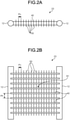
- FIG. 2 is a diagram for explaining the heat exchanger 23 according to the present embodiment
- FIG. 2A is a plan view of the heat exchanger 23
- FIG. 2B is a front view of the heat exchanger 23.
- the heat exchanger 23 includes: a plurality of flat tubes 40 as heat transfer tubes each having an oval cross-sectional shape or a rectangular shape with rounded corners, the plurality of flat tubes 40 being arranged in a vertical direction (a direction perpendicular to the refrigerant flow direction) such that side surfaces (wide surfaces) thereof face each other; a pair of left and right headers 12 connected to both ends of the plurality of flat tubes 40; and a plurality of fins 50 disposed in a direction intersecting with a direction in which the flat tubes 40 extend and bonded to each of the flat tubes 40 overall.
- the heat exchanger 23 is disposed in the outdoor unit 2 such that the direction, in which the plurality of flat tubes 40 are arranged (the longitudinal direction of the fins 50), is parallel to the direction of gravity.
- the upper flat tube 40 in the drawing may be referred to as first flat tube 40a
- the lower flat tube 40 in the drawing may be referred to as second flat tube 40b.
- the heat exchanger 23 includes refrigerant pipes connected to the headers 12 (not illustrated), the refrigerant pipes connecting the heat exchanger 23 to other components of the air conditioner 1 to allow the refrigerant to flow therethrough.
- the flat tube 40 has a flat shape with respect to the vertical direction, and is provided along a direction in which the refrigerant flows between the pair of headers 12 (the longitudinal direction of the flat tube 40) while allowing air to flow along the lateral direction of the flat tube 40.
- a plurality of refrigerant flow paths 41 for the refrigerant to flow therethrough along the longitudinal direction of the flat tube 40, are formed inside the flat tube 40 side by side in the lateral direction of the flat tube 40.
- the plurality of flat tubes 40 are arranged in parallel to each other in the vertical direction with a gap S1 therebetween for passage of air, and both ends of each of the flat tubes 40 are connected to the pair of headers 12, respectively.
- the plurality of flat tubes 40 extending in the longitudinal direction are arranged at a predetermined arrangement pitch Ph with respect to the vertical direction (a distance of the gap S1 in the vertical direction), and both ends of each of the flat tubes 40 are connected to the headers 12, respectively.
- the header 12 is formed in a cylindrical shape, and the refrigerant flow paths (not illustrated) are formed inside the header 12 such that the refrigerant supplied to the heat exchanger 23 is split to flow into the plurality of flat tubes 40 or the refrigerant flowing out of the plurality of flat tubes 40 joins together.
- the fins 50 are formed in a flat plate shape when viewed from the front of the heat exchanger 23, and are arranged to be stacked in the longitudinal direction of the flat tubes 40 in such a manner as to intersect with the flat tubes 40.
- the plurality of fins 50 are arranged in parallel to each other with a gap S1 therebetween for passage of air.
- the plurality of fins 50 formed along the vertical direction are arranged at a predetermined fin pitch Pv with respect to the longitudinal direction of the flat tubes 40 (a distance of the gap S1 in the longitudinal direction of the flat tubes 40).
- first fin 50a the left fin 50 in the drawing
- second fin 50b the right fin 50 in the drawing
- a plurality of notches 51 are arranged side by side in the vertical direction in the fin 50 for the plurality of flat tubes 40 to be inserted thereinto, respectively.
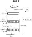
- the fin 50 has a plurality of intermediate portions 52 (portions on the leeward side) each formed between two notches 51 (a first notch 51a and a second notch 51b) positioned adjacent to each other in the vertical direction, and a connecting portion 53 (a portion on the windward side) connecting the intermediate portions 52 to each other.
- first notch 51a the upper notch 51 in the drawing
- second notch 51b the lower notch 51 in the drawing
- the first flat tube 40a is inserted into the first notch 51a
- the second flat tube 40b is inserted into the second notch 51b.
- the plurality of refrigerant flow paths 41 for the refrigerant to flow therethrough are provided inside the flat tube 40, and the plurality of refrigerant flow paths 41 are arranged along the lateral direction of the flat tube 40 (a direction in which air flows).
- the fin 50 has a first bulging portion 54 bulging in a thickness direction of the fin 50 (the longitudinal direction of the flat tube) between the first notch 51a and the second notch 51b. That is, in the vertical direction, the first notch 51a is located above the first bulging portion 54, and the second notch is located below the first bulging portion 54.
- the first bulging portion 54 has an upper end edge X 1 -X 2 positioned from the intermediate portion 52 to the connecting portion 53 to straddle a boundary between the intermediate portion 52 and the connecting portion 53, and a lower end edge Z 1 -Z 2 positioned in the connecting portion 53.
- the first bulging portion 54 is formed such that a first upper end X 1 of the first bulging portion 54 positioned on the intermediate portion 52 side is higher than a second upper end X 2 of the first bulging portion 54 positioned on the connecting portion 53 side, or the first upper end X 1 is positioned at the same height as the second upper end X 2 . That is, although it is illustrated in FIG. 4A that the first upper end X 1 and the second upper end X 2 are positioned at the same height in the direction of gravity, but the first upper end X 1 may be positioned to be higher than the second upper end X 2 in the direction of gravity.
- the upper end edge X 1 -X 2 of the first bulging portion 54 is set at an appropriate position with respect to the first flat tube 40a (not illustrated, see FIG. 3 ) inserted into the first notch 51a above the first bulging portion 54.
- condensed water adhering to the periphery of the first flat tube 40a flows through a windward end (a right end in the drawing) of the first notch 51a (first flat tube 40a) along a direction W toward an edge of the first notch 51a, and reaches the upper end edge X 1 -X 2 of the first bulging portion 54.
- the condensed water After reaching the upper end edge X 1 -X 2 , the condensed water is substantially equally split into two flows, that is, a flow in a direction W 1 in which the condensed water is transferred along an intermediate portion-side edge X 1 -Z 1 connecting the first upper end X 1 and the second lower end Z 1 to each other, and a flow in a direction W 2 in which the condensed water is transferred along a connecting portion-side edge X 2 -Z 2 connecting the second upper end X 2 and the second lower end Z 2 to each other.
- FIG. 4B illustrates a first bulging portion 54A as a comparative example.
- a first upper end X 1 is formed to be lower than a second upper end X 2 in the direction of gravity.
- the first bulging portion 54 makes it possible to smoothly discharge the condensed water downward along the connecting portion 53, while preventing the condensed water from flowing intensively on the intermediate portion 52 side.
- the first bulging portion 54 in order to smoothly discharge the condensed water retained around the first flat tube 40a, is preferably formed such that a distance d1 between the first upper end X 1 of the first bulging portion 54 and a lower side of the first notch 51a in the vertical direction is in a range of 4 mm or less.
- FIG. 5 is a side view of the heat exchanger 23
- FIG. 6 is a front view of the heat exchanger 23.
- the condensed water adheres onto one or both of the flat tubes 40 and the fins 50 as droplets, and a relationship between a contact angle with respect to each of the flat tubes 40 and the fins 50 and a surface tension, is represented by the following Young's equation, which is a relationship illustrated in FIG. 7 .
- ⁇ S ⁇ L • cos ⁇ + ⁇ SL where ⁇ is a contact angle
- FIGS. 13A and 13B are diagrams for comparing sizes d2 of condensed water (droplets) retained around the first flat tube 40a at different contact angles ⁇ .
- FIG. 13A illustrates an average value of measurement results of droplet sizes d2 at each fin pitch (1.0 mm, 1.5 mm, or 2.0 mm) when the contact angle ⁇ is 10°.
- FIG. 13B illustrates an average value of measurement results of droplet sizes d2 at each fin pitch (1.0 mm, 1.5 mm, or 2.0 mm) when the contact angle ⁇ is 60°.
- fin pitches Pv between the fins 50 were set to three kinds, i.e. 1.0 mm, 1.5 mm, and 2.0 mm, and droplet sizes d2 of the condensed water were measured (1) in a case where the contact angle ⁇ was 10 degrees as a state in which the surfaces of the fins 50 sufficiently functioned for hydrophilic processing and (2) in a case where the contact angle ⁇ was 60 degrees as a state in which the surfaces of the fins 50 did not function for hydrophilic processing due to deterioration or contamination. Note that the contact angle ⁇ was adjusted by mixing a surfactant with water forming a droplet.
- the contact angle ⁇ of the droplet was reduced by increasing an amount of the surfactant.
- the fins 50 formed of an acrylic material were used.
- the fins 50 formed of an acrylic material differs from actual fins formed of an aluminum material in how easily the water spreads on the surfaces of the fins. Therefore, by adjusting the amount of the surfactant such that the contact angle ⁇ with respect to the acrylic fin is equal to that with respect to the aluminum fin, the verification can be performed without being influenced even though the material is different from that of the actual fin.
- the contact angle ⁇ of the droplet retained on the surface of the fin subjected to the hydrophilic treatment is set to 20° or to 20° or less.
- the distance d1 between the first upper end X 1 of the first bulging portion 54 and the lower side of the first notch 51a may be set to correspond to a droplet size d2 at a contact angle ⁇ of 20° in a non-used product state.
- the distance d1 between the first upper end X 1 of the first bulging portion 54 and the lower side of the first notch 51a as illustrated in FIG. 8B is set to 4 mm or less, even when the contact angle ⁇ is 20° at which the droplet size d2 of the condensed water is small (in a state where the surface of the fin 50 sufficiently functions for hydrophilic processing), the distance d1 can be smaller than a minimum droplet size d2, and the droplet can reach the first upper end X 1 of the first bulging portion 54.
- the water droplets of the condensed water reach the first upper end X 1 of the first bulging portion 54, the water droplets wet-spread on the upper end edge X 1 -X 2 due to the influence of surface tension, and pass through the first upper end X 1 and the second upper end X 2 again to the intermediate portion-side edge X 1 -Z 1 and the connecting portion-side edge X 2 -Z 2 .
- the water droplets are influenced by gravity in addition to the influence of surface tension on the intermediate portion-side edge X 1 -Z 1 and the connecting portion-side edge X 2 -Z 2 .
- the first bulging portion 54 makes it easy to discharge the water droplets.
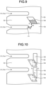
- the first bulging portion 54 is preferably formed such that a horizontal-direction distance (a distance in a direction orthogonal to the vertical direction) d3 between the first lower end Z 1 positioned on the intermediate portion 52 side of the first bulging portion 54 and a connecting portion-side end Y 1 of the second notch 51b, is 1/5 or more of a gravity-direction distance (a distance in the vertical direction) d4 between the first lower end Z 1 and the connecting portion-side end Y 1 of the second notch 51b positioned on the connecting portion 53 side.
- the connecting portion-side end Y 1 of the second notch 51b in the present embodiment is formed to bulge toward the connecting portion 53 in an arc shape.
- the connecting portion-side end Y 1 is positioned at the center between an upper side and a lower side of the second notch 51.
- a relative positional relationship between the first lower end Z 1 and the connecting portion-side end Y 1 may be set based on a relationship between the gravity force and the drag force in a state where the radius of the water droplet has become large to some extent (e.g. 0.6 mm).
- the gravity force F is compared with the drag force D, the gravity force F is six times larger than the drag force D.
- the horizontal-direction distance d3 is preferably less than 1/6 times the gravity-direction distance d4.
- a second bulging portion 55 may be further provided below the lower end edge Z 1 -Z 2 of the first bulging portion 54.
- An upper end edge V 1 -V 2 of the second bulging portion 55 is disposed close to and below the lower end edge Z 1 -Z 2 of the first bulging portion 54.
- a lower end edge U 1 -U 2 of the second bulging portion 55 does not intersect with the upper end edge X 1 -X 2 of the first bulging portion 54.
- the second bulging portion 55 is provided such that water droplets falling down from the first bulging portion 54 is guided from the first bulging portion 54 to another first bulging portion 54 downwardly via the second bulging portion 55, without being scattered by the influence of wind.
- the second bulging portion 55 may be formed such that the upper end edge V 1 -V 2 of the second bulging portion 55 is positioned within a range of 4 mm or less from the lower end edge Z 1 -Z 2 of the first bulging portion 54 in the vertical direction. The reason is the same as that why the distance d1 between the first upper end X 1 of the first bulging portion 54 and the lower side of the first notch 51a is set to 4 mm or less as described above.
- the mechanical strength of the fin 50 can be increased to suppress bending of the fin 50 in an assembly process or the like.
- the mechanical strength of the connecting portion 53 near the notch 51 can also be increased to suppress bending of the fin 50 in an assembly process or the like.
- the first lower end Z 1 is positioned in the connecting portion 53.
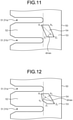
- a point dmax (the first lower end Z 1 in FIG. 11 ), at which a perpendicular distance d of a connection line passing along the edges of the first bulging portion 54 from the first upper end X 1 from a straight line connecting the first upper end X 1 and the second lower end Z 2 to each other is maximum, is positioned in the connecting portion 53.
- FIG. 12 illustrates a first bulging portion 54 in a comparative example.
- a point Y 2 at which a perpendicular distance d to a connection line passing along edges of the first bulging portion 54 from the first upper end X 1 from a straight line connecting a first upper end X 1 and a second lower end Z 2 to each other is maximum, is positioned in the intermediate portion 52.
- condensed water flowing along an intermediate portion-side edge X 1 -Z 1 from the first upper end X 1 stagnates at the point Y 2 due to surface tension, and then flows toward an intermediate portion-side lower end Z 1 .
- the condensed water retained at the point Y 2 may drop onto the second flat tube 40b (not illustrated) inserted into the second notch 51b due to the influence of gravity or wind.
- the condensed water retained around the flat tube 40 can be reduced, thereby shortening a time period during which the condensed water is discharged.
- the condensed water flowing from the upper surface to the lower surface of the flat tube 40 and the condensed water generated on the lower surface of the flat tube 40 can be influenced by surface tension and gravity, thereby smoothly discharging the condensed water.
- the connecting portion 53 of the fin 50 is positioned on the windward side, the condensed water discharged from the first bulging portion 54, can be prevented from flowing toward the region of the flat tube 40, thereby smoothly discharging the condensed water.
- the second bulging portion 55 is provided below the first bulging portion 54, the condensed water can be smoothly discharged without being influenced by wind.
Landscapes
- Engineering & Computer Science (AREA)
- Physics & Mathematics (AREA)
- Thermal Sciences (AREA)
- Mechanical Engineering (AREA)
- General Engineering & Computer Science (AREA)
- Geometry (AREA)
- Chemical & Material Sciences (AREA)
- Combustion & Propulsion (AREA)
- Heat-Exchange Devices With Radiators And Conduit Assemblies (AREA)
- Air Filters, Heat-Exchange Apparatuses, And Housings Of Air-Conditioning Units (AREA)
Abstract
Description
- The present invention relates to a heat exchanger and an air conditioner including the heat exchanger. Background
- Conventionally, a heat exchanger using flat tubes in an air conditioner, has been known. In such a heat exchanger, when condensed water is retained in a water droplet form on a surface of at least one of flat tubes and fins, heat exchange between working fluid flowing through flow paths in the flat tubes and gas passing between the fins, is hindered by the condensed water, resulting in a bad influence on the performance of the heat exchanger.
- In this regard, there has been disclosed a technique in which when an air conditioner is installed, a bulging portion guiding condensed water in the direction of gravity, is provided on a fin, to improve discharge of the condensed water (for example, see Patent Literature 1). Specifically, in this technique, the bulging portion formed to protrude from a flat portion of the fin, is formed in a shape in which a first end of the bulging portion is positioned in a region between upper and lower notches into which flat tubes are inserted, and a second end of the bulging portion is positioned to be lower than the first end in a region in which there is no notch.
- However, the technique of
Patent Literature 1 has a problem in that while the discharge of the condensed water adhering to the fins can be improved, the shape does not have a structure capable of actively discharging the condensed water retained around the flat tubes. That is, water droplets retained on lower surfaces of the flat tubes in a state where a surface tension, a gravity force, a static friction coefficient, and the like are balanced, are not discharged until the water droplets greatly grow so that the gravity force exceeds a force acting in a direction opposite to the direction of gravity such as the surface tension. As illustrated inFIG. 4B , a large amount of the condensed water flows intensively along an intermediate portion-side edge X1-Z1 toward a direction W1 in a bulgingportion 54A. As a result, a small amount of the condensed water flows along a connecting portion-side edge X2-Z2 toward a direction W2. Then, due to the influence of gravity, some of the large amount of the condensed water transferred in the direction W1, is transferred in a direction W3, and drops onto a second flat tube 40b (seeFIG. 3 ) that is inserted into asecond notch 51b, which is provided below the bulgingportion 54A. - Patent Literature 1:
WO 2016/194043 A - The present invention has been made in view of the above, and an object of the present invention is to provide a heat exchanger capable of improving discharging of condensed water retained on surfaces of both fins and flat tubes, and an air conditioner including the heat exchanger.
- According to an aspect of the embodiments, a heat exchanger includes: a plurality of flat tubes; a fin in which a plurality of notches are arranged side by side in a vertical direction for the plurality of flat tubes to be inserted thereinto, respectively, the fin having a plurality of intermediate portions, each formed between two of the notches positioned adjacent to each other in the vertical direction, and a connecting portion connecting the intermediate portions to each other; and a first bulging portion having an upper end edge and a lower end edge provided between a first notch and a second notch, the first notch being an upper notch and the second notch being a lower notch between the two notches positioned adjacent to each other in the vertical direction with the intermediate portion interposed therebetween, and the upper end edge being positioned in the intermediate portion and the lower end edge being positioned in the connecting portion, wherein the upper end edge has a first upper end positioned on an intermediate portion side, and a second upper end positioned on a connecting portion side, the first upper end being positioned to be higher than the second upper end, or the first upper end being positioned at the same height as the second upper end.
- According to the present invention, it is possible to improve discharging of condensed water retained on the surfaces of both the fins and the flat tubes.
-
-
FIG. 1A is a refrigerant circuit diagram illustrating an example of an air conditioner according to an embodiment. -
FIG. 1B is a block diagram of a control unit illustrating the example of the air conditioner according to the embodiment. -
FIG. 2A is a plan view of an outdoor heat exchanger illustrating the outdoor heat exchanger according to the embodiment. -
FIG. 2B is a front view of the outdoor heat exchanger illustrating the outdoor heat exchanger according to the embodiment. -
FIG. 3 is a view illustrating a relationship between a flat tube and a fin. -
FIG. 4A is a view illustrating a first bulging portion in the embodiment. -
FIG. 4B is a view illustrating a first bulging portion in a comparative example. -
FIG. 5 is a side view illustrating a positional relationship of the first bulging portion. -
FIG. 6 is a front view illustrating the positional relationship of the first bulging portion. -
FIG. 7 is a view illustrating a contact angle between a liquid and a solid. -
FIG. 8A is a front view illustrating a distance between an upper end edge of the first bulging portion and a lower side of a first notch. -
FIG. 8B is a side view illustrating the distance between the upper end edge of the first bulging portion and the lower side of the first notch. -
FIG. 9 is a view illustrating a distance between a lower end edge of the first bulging portion and an intermediate portion-side end of a second notch. -
FIG. 10 is a view illustrating an aspect in which a second bulging portion is further provided. -
FIG. 11 is a side view illustrating a positional relationship of the first bulging portion. -
FIG. 12 is a side view illustrating a positional relationship of a first bulging portion in a comparative example. -
FIG. 13A is a view for comparing sizes d2 of condensed water (droplet) retained around a first flat tube 40a at different contact angles θ, and is a view illustrating droplet sizes d2 when the contact angle θ is 10°. -
FIG. 13B is a view for comparing sizes d2 of condensed water (droplet) retained around a first flat tube 40a at different contact angles θ, and is a view illustrating respective droplet sizes d2 when the contact angle θ is 60°. - Hereinafter, an embodiment of the present invention will be described in detail with reference to the accompanying drawings. Note that the present invention is not limited to the following embodiment, and various modifications can be made without departing from the gist of the present invention.
- First, a refrigerant circuit of an
air conditioner 1 including anoutdoor unit 2, will be described with reference toFIG. 1A . As illustrated inFIG. 1A , theair conditioner 1 in the present embodiment includes anoutdoor unit 2 that is installed outdoors, and an indoor unit 3 thai is installed indoors and connected to theoutdoor unit 2 through a liquid pipe 4 and agas pipe 5. Specifically, a liquid-side shutoff valve 25 of theoutdoor unit 2 and a liquidpipe connection portion 33 of the indoor unit 3 are connected to each other by the liquid pipe 4. In addition, a gas-side shutoff valve 26 of theoutdoor unit 2 and a gaspipe connection portion 34 of the indoor unit 3 are connected to each other by thegas pipe 5. As described above, arefrigerant circuit 10 of theair conditioner 1 is formed. - First, the
outdoor unit 2 will be described. Theoutdoor unit 2 includes acompressor 21, a four-way valve 22, anoutdoor heat exchanger 23, anexpansion valve 24, a liquid-side shutoff valve 25 to which the liquid pipe 4 is connected, a gas-side shutoff valve 26 to which thegas pipe 5 is connected, and anoutdoor fan 27. These devices, excluding theoutdoor fan 27, are connected to each other by refrigerant pipes, which will be described later, to form an outdoorunit refrigerant circuit 10a constituting a part of therefrigerant circuit 10. Note that an accumulator (not illustrated) may be provided on a refrigerant suction side of thecompressor 21. - The
compressor 21 is a capacity-variable compressor whose rotational speed can be controlled by an inverter, which is not illustrated, to change an operating capacity. On a refrigerant discharge side of thecompressor 21, adischarge pipe 61 is connected to a port a of the four-way valve 22. On the refrigerant suction side of thecompressor 21, asuction pipe 66 is connected to a port c of the four-way valve 22. - The four-
way valve 22 is a valve for switching a refrigerant flow direction, and includes four ports a, b, c, and d. As described above, the port a is connected to the refrigerant discharge side of thecompressor 21 by thedischarge pipe 61. The port b is connected to one refrigerant inlet/outlet port of theoutdoor heat exchanger 23 by arefrigerant pipe 62. As described above, the port c is connected to the refrigerant suction side of thecompressor 21 by thesuction pipe 66. The port d is connected to the gas-side shutoff valve 26 by an outdoorunit gas pipe 64. - The
outdoor heat exchanger 23 exchanges heat between the refrigerant and outside air introduced into theoutdoor unit 2 as theoutdoor fan 27 rotates, which will be described later. One refrigerant inlet/outlet port of theoutdoor heat exchanger 23 is connected to the port b of the four-way valve 22 by therefrigerant pipe 62 as described above, and the other refrigerant inlet/outlet port of theoutdoor heat exchanger 23 is connected to the liquid-side shutoff valve 25 by an outdoor unit liquid pipe 63. Theoutdoor heat exchanger 23 functions as a condenser during a cooling operation, and functions as an evaporator during a heating operation by switching the four-way valve 22. - The
expansion valve 24 is an electronic expansion valve driven by a pulse motor, which is not illustrated. Specifically, an opened degree of theexpansion valve 24 is adjusted based on the number of pulses applied to the pulse motor. During the heating operation, the opened degree of theexpansion valve 24 is adjusted such that a discharge temperature, which is a temperature of the refrigerant discharged fromcompressor 21, reaches a predetermined target temperature. - The
outdoor fan 27 is formed of a resin material, and is disposed near theoutdoor heat exchanger 23. A central portion of theoutdoor fan 27 is supported by a rotation shaft of a fan motor, which is not illustrated. The fan motor rotates to rotate theoutdoor fan 27. By the rotation of theoutdoor fan 27, outside air is introduced into theoutdoor unit 2 through a suction port, which is not illustrated, of theoutdoor unit 2, and the outside air having exchanged heat with the refrigerant in theoutdoor heat exchanger 23, is released to the outside of theoutdoor unit 2 through a blow-out port, which is not illustrated, of theoutdoor unit 2. - In addition to the configuration described above, various sensors are provided in the
outdoor unit 2. As illustrated inFIG. 1A , adischarge pressure sensor 71 detecting a pressure of the refrigerant discharged from thecompressor 21, and adischarge temperature sensor 73 detecting a temperature of the refrigerant discharged from the compressor 21 (the discharge temperature described above), are provided in thedischarge pipe 61. Asuction pressure sensor 72 detecting a pressure of the refrigerant sucked into thecompressor 21, and asuction temperature sensor 74 detecting a temperature of the refrigerant sucked into thecompressor 21, are provided in thesuction pipe 66. - A heat
exchange temperature sensor 75 detecting an outdoor heat exchange temperature, which is a temperature of theoutdoor heat exchanger 23, is provided at a substantially middle portion of a refrigerant path, which is not illustrated, included in theoutdoor heat exchanger 23. An outsideair temperature sensor 76 detecting a temperature of outside air introduced into theoutdoor unit 2, that is, an outside air temperature, is provided near the suction port, which is not illustrated, of theoutdoor unit 2. - In addition, the
outdoor unit 2 includes an outdoor unit control means 200. The outdoor unit control means 200 is mounted on a control board housed in an electric component box, which is not illustrated, of theoutdoor unit 2. As illustrated inFIG. 1B , the outdoor unit control means 200 includes a CPU 210, astorage unit 220, acommunication unit 230, and a sensor input unit 240. - The
storage unit 220 includes a flash memory, and stores a program for controlling theoutdoor unit 2, detection values corresponding to detection signals from the various sensors, states in which thecompressor 21, theoutdoor fan 27, and the like are controlled, etc. Although not illustrated, thestorage unit 220 stores, in advance, a rotational speed table in which a rotational speed of thecompressor 21 is defined based on a demanded capability to be received from the indoor unit 3. - The
communication unit 230 is an interface for communication with the indoor unit 3. The sensor input unit 240 receives detection results from the various sensors of theoutdoor unit 2, and outputs the detection results to the CPU 210. - The CPU 210 receives the respective detection results from the above-described sensors of the
outdoor unit 2 via the sensor input unit 240. Further, the CPU 210 receives a control signal transmitted from the indoor unit 3 via thecommunication unit 230. The CPU 210 controls driving of thecompressor 21, theoutdoor fan 27, on the basis of the received detection results, control signal, and the like. In addition, the CPU 210 controls switching of the four-way valve 22 on the basis of the received detection results and control signal. Further, the CPU 210 adjusts an opened degree of theexpansion valve 24 based on the received detection results and control signal. - Next, the indoor unit 3 will be described with reference to
FIG. 1A . The indoor unit 3 includes anindoor heat exchanger 31, anindoor fan 32, a liquidpipe connection portion 33 to which the other end of the liquid pipe 4 is connected, and a gaspipe connection portion 34 to which the other end of thegas pipe 5 is connected. These devices, excluding theindoor fan 32, are connected to each other by refrigerant pipes, which will be described in detail below, to form an indoor unitrefrigerant circuit 10b constituting a part of therefrigerant circuit 10. - The
indoor heat exchanger 31 exchanges heat between indoor air introduced into the indoor unit 3 from a suction port, which is not illustrated, of the indoor unit 3 and the refrigerant as theindoor fan 32 rotates, which will be described later. One refrigerant inlet/outlet port of theindoor heat exchanger 31 is connected to the liquidpipe connection portion 33 by an indoor unitliquid pipe 67. The other refrigerant inlet/outlet port of theindoor heat exchanger 31 is connected to the gaspipe connection portion 34 by an indoorunit gas pipe 68. Theindoor heat exchanger 31 functions as an evaporator when the indoor unit 3 performs a cooling operation, and functions as a condenser when the indoor unit 3 performs a heating operation. - The
indoor fan 32 is formed of a resin material, and is disposed near theindoor heat exchanger 31. Theindoor fan 32 is rotated by a fan motor, which is not illustrated, to introduce indoor air into the indoor unit 3 through the suction port, which is not illustrated, of the indoor unit 3, and release the indoor air having exchanged heat with the refrigerant in theindoor heat exchanger 31 into an indoor space through a blow-out port, which is not illustrated, of the indoor unit 3. - In addition to the configuration described above, various sensors are provided in the indoor unit 3. A liquid-
side temperature sensor 77 detecting a temperature of the refrigerant flowing into theindoor heat exchanger 31 or flowing out of theindoor heat exchanger 31, is provided in the indoor unitliquid pipe 67. A gas-side temperature sensor 78 detecting a temperature of the refrigerant flowing out of theindoor heat exchanger 31 or flowing into theindoor heat exchanger 31, is provided in the indoorunit gas pipe 68. Aroom temperature sensor 79 detecting a temperature of the indoor air flowing into the indoor unit 3, that is, a room temperature, is provided near the suction port, which is not illustrated, of the indoor unit 3. - In addition, the indoor unit 3 includes an indoor unit control means 300. As illustrated in
FIG. 1B , the indoor unit control means 300 includes a CPU 310, astorage unit 320, acommunication unit 330, and a sensor input unit 340 (in the present specification, the indoor unit control means 300 may be referred to simply as control means). - The
storage unit 320 includes a flash memory, and stores a program for controlling the indoor unit 3, detection values corresponding to detection signals from the various sensors, states in which theindoor fan 32 and the like are controlled, etc. Although not illustrated, thestorage unit 320 stores, in advance, a rotational speed table or the like in which a rotational speed of theindoor fan 32 is defined, including a rotational speed for monitoring a leakage of the refrigerant while the operation is stopped, which will be described later. - The
communication unit 330 is an interface for communication with theoutdoor unit 2. The sensor input unit 340 receives detection results from the various sensors of the indoor unit 3, and outputs the detection results to the CPU 310. - The CPU 310 receives the respective detection results from the above-described sensors of the indoor unit 3 via the sensor input unit 340. Further, the CPU 310 receives a control signal transmitted from the
outdoor unit 2 via thecommunication unit 330. The CPU 310 controls driving of theindoor fan 32, including driving for monitoring a leakage of the refrigerant while the operation is stopped, which will be described later, on the basis of the received detection results and control signal. In addition, the CPU 310 calculates a temperature difference between a set temperature set by a user operating a remote controller, which is not illustrated, and a room temperature detected by theroom temperature sensor 79, and transmits a demanded capability based on the calculated temperature difference to the outdoor unit control means 200 of theoutdoor unit 2 via thecommunication unit 330. - Next, a flow of a refrigerant and an operation of each unit in the
refrigerant circuit 10 during an air conditioning operation of theair conditioner 1 in the present embodiment, will be described with reference toFIG. 1A . Hereinafter, the description will be provided, assuming that the indoor unit 3 performs a heating operation based on a flow of the refrigerant indicated by a solid line in the drawing. Note that a flow of the refrigerant indicated by a broken line represents a cooling operation. - When the indoor unit 3 performs the heating operation, the CPU 210 switches the four-
way valve 22 to be in a state indicated by the solid line inFIG. 1A , that is, to connect the port a and the port d of the four-way valve 22 to each other, and connect the port b and the port c of the four-way valve 22 to each other. As a result, the refrigerant circulates in therefrigerant circuit 10 in a direction indicated by solid arrows for a heating cycle, in which theoutdoor heat exchanger 23 functions as an evaporator and theindoor heat exchanger 31 functions as a condenser. - The high-pressure refrigerant discharged from the
compressor 21, flows through thedischarge pipe 61 into the four-way valve 22. The refrigerant flowing into the port a of the four-way valve 22, flows into the outdoorunit gas pipe 64 through the port d of the four-way valve 22, and then flows into thegas pipe 5 via the gas-side shutoff valve 26. The refrigerant flowing through thegas pipe 5 flows into the indoor unit 3 via the gaspipe connection portion 34. - The refrigerant introduced into the indoor unit 3, flows through the indoor
unit gas pipe 68 into theindoor heat exchanger 31 to exchange heat with indoor air introduced into the indoor unit 3 as theindoor fan 32 rotates, so that the refrigerant is condensed. As described above, theindoor heat exchanger 31 functions as a condenser, and the indoor air having exchanged heat with the refrigerant in theindoor heat exchanger 31, is blown into the indoor space from the blow-out port, which is not illustrated, thereby heating the indoor space, in which the indoor unit 3 is installed. - The refrigerant discharged from the
indoor heat exchanger 31, flows through the indoor unitliquid pipe 67 into the liquid pipe 4 via the liquidpipe connection portion 33. The refrigerant introduced into theoutdoor unit 2 via the liquid-side shutoff valve 25 after flowing through the liquid pipe 4, is decompressed at the time of passing through theexpansion valve 24 while flowing through the outdoor unit liquid pipe 63. As described above, the opened degree of theexpansion valve 24 during the heating operation, is adjusted such that the discharge temperature of thecompressor 21 reaches the predetermined target temperature. - The refrigerant introduced into the
outdoor heat exchanger 23 after passing through theexpansion valve 24 exchanges heat with the outside air introduced into theoutdoor unit 2 as theoutdoor fan 27 rotates, so that the refrigerant is evaporated. The refrigerant discharged from theoutdoor heat exchanger 23 into therefrigerant pipe 62 flows through the port b and the port c of the four-way valve 22 and thesuction pipe 66, and is sucked into thecompressor 21 so that the refrigerant is compressed again. - The heat exchanger of the present embodiment can be applied to the
indoor heat exchanger 31 of the indoor unit 3 and theoutdoor heat exchanger 23 of theoutdoor unit 2. However, in the following description, the heat exchanger of the present embodiment is applied to the outdoor heat exchanger (hereinafter, referred to simply as heat exchanger) 23 functioning as an evaporator during the heating operation of theoutdoor unit 2. -
FIG. 2 is a diagram for explaining theheat exchanger 23 according to the present embodiment, andFIG. 2A is a plan view of theheat exchanger 23 andFIG. 2B is a front view of theheat exchanger 23. As illustrated inFIGS. 2A and 2B , theheat exchanger 23 includes: a plurality offlat tubes 40 as heat transfer tubes each having an oval cross-sectional shape or a rectangular shape with rounded corners, the plurality offlat tubes 40 being arranged in a vertical direction (a direction perpendicular to the refrigerant flow direction) such that side surfaces (wide surfaces) thereof face each other; a pair of left andright headers 12 connected to both ends of the plurality offlat tubes 40; and a plurality offins 50 disposed in a direction intersecting with a direction in which theflat tubes 40 extend and bonded to each of theflat tubes 40 overall. Theheat exchanger 23 is disposed in theoutdoor unit 2 such that the direction, in which the plurality offlat tubes 40 are arranged (the longitudinal direction of the fins 50), is parallel to the direction of gravity. In the following description, with respect to twoflat tubes 40 adjacent to each other in the vertical direction among the plurality offlat tubes 40, the upperflat tube 40 in the drawing may be referred to as first flat tube 40a, and the lowerflat tube 40 in the drawing may be referred to as second flat tube 40b. Note that, in addition to these components, theheat exchanger 23 includes refrigerant pipes connected to the headers 12 (not illustrated), the refrigerant pipes connecting theheat exchanger 23 to other components of theair conditioner 1 to allow the refrigerant to flow therethrough. - More specifically, the
flat tube 40 has a flat shape with respect to the vertical direction, and is provided along a direction in which the refrigerant flows between the pair of headers 12 (the longitudinal direction of the flat tube 40) while allowing air to flow along the lateral direction of theflat tube 40. A plurality ofrefrigerant flow paths 41 for the refrigerant to flow therethrough along the longitudinal direction of theflat tube 40, are formed inside theflat tube 40 side by side in the lateral direction of theflat tube 40. As illustrated inFIG. 2B , the plurality offlat tubes 40 are arranged in parallel to each other in the vertical direction with a gap S1 therebetween for passage of air, and both ends of each of theflat tubes 40 are connected to the pair ofheaders 12, respectively. Specifically, the plurality offlat tubes 40 extending in the longitudinal direction, are arranged at a predetermined arrangement pitch Ph with respect to the vertical direction (a distance of the gap S1 in the vertical direction), and both ends of each of theflat tubes 40 are connected to theheaders 12, respectively. - The
header 12 is formed in a cylindrical shape, and the refrigerant flow paths (not illustrated) are formed inside theheader 12 such that the refrigerant supplied to theheat exchanger 23 is split to flow into the plurality offlat tubes 40 or the refrigerant flowing out of the plurality offlat tubes 40 joins together. - The
fins 50 are formed in a flat plate shape when viewed from the front of theheat exchanger 23, and are arranged to be stacked in the longitudinal direction of theflat tubes 40 in such a manner as to intersect with theflat tubes 40. The plurality offins 50 are arranged in parallel to each other with a gap S1 therebetween for passage of air. Specifically, the plurality offins 50 formed along the vertical direction, are arranged at a predetermined fin pitch Pv with respect to the longitudinal direction of the flat tubes 40 (a distance of the gap S1 in the longitudinal direction of the flat tubes 40). In the following description, with respect to twofins 50 adjacent to each other in a horizontal direction among the plurality offins 50, theleft fin 50 in the drawing may be referred to as first fin 50a, and theright fin 50 in the drawing may be referred to as second fin 50b. - Next, a relationship between the
flat tube 40, thefin 50, and a first bulgingportion 54 will be described with reference toFIG. 3 and the subsequent drawings. First, as illustrated inFIG. 3 , a plurality ofnotches 51 are arranged side by side in the vertical direction in thefin 50 for the plurality offlat tubes 40 to be inserted thereinto, respectively. Thefin 50 has a plurality of intermediate portions 52 (portions on the leeward side) each formed between two notches 51 (afirst notch 51a and asecond notch 51b) positioned adjacent to each other in the vertical direction, and a connecting portion 53 (a portion on the windward side) connecting theintermediate portions 52 to each other. In the following description, with respect to twonotches 51 adjacent to each other with anintermediate portion 52 interposed therebetween among the plurality ofnotches 51, theupper notch 51 in the drawing may be referred to asfirst notch 51a, and thelower notch 51 may be referred to assecond notch 51b. The first flat tube 40a is inserted into thefirst notch 51a, and the second flat tube 40b is inserted into thesecond notch 51b. The plurality ofrefrigerant flow paths 41 for the refrigerant to flow therethrough are provided inside theflat tube 40, and the plurality ofrefrigerant flow paths 41 are arranged along the lateral direction of the flat tube 40 (a direction in which air flows). - As illustrated in
FIG. 4A , thefin 50 has a first bulgingportion 54 bulging in a thickness direction of the fin 50 (the longitudinal direction of the flat tube) between thefirst notch 51a and thesecond notch 51b. That is, in the vertical direction, thefirst notch 51a is located above the first bulgingportion 54, and the second notch is located below the first bulgingportion 54. The first bulgingportion 54 has an upper end edge X1-X2 positioned from theintermediate portion 52 to the connectingportion 53 to straddle a boundary between theintermediate portion 52 and the connectingportion 53, and a lower end edge Z1-Z2 positioned in the connectingportion 53. The first bulgingportion 54 is formed such that a first upper end X1 of the first bulgingportion 54 positioned on theintermediate portion 52 side is higher than a second upper end X2 of the first bulgingportion 54 positioned on the connectingportion 53 side, or the first upper end X1 is positioned at the same height as the second upper end X2. That is, although it is illustrated inFIG. 4A that the first upper end X1 and the second upper end X2 are positioned at the same height in the direction of gravity, but the first upper end X1 may be positioned to be higher than the second upper end X2 in the direction of gravity. - As will be described in detail later, the upper end edge X1-X2 of the first bulging
portion 54 is set at an appropriate position with respect to the first flat tube 40a (not illustrated, seeFIG. 3 ) inserted into thefirst notch 51a above the first bulgingportion 54. As a result, condensed water adhering to the periphery of the first flat tube 40a flows through a windward end (a right end in the drawing) of thefirst notch 51a (first flat tube 40a) along a direction W toward an edge of thefirst notch 51a, and reaches the upper end edge X1-X2 of the first bulgingportion 54. - After reaching the upper end edge X1-X2, the condensed water is substantially equally split into two flows, that is, a flow in a direction W1 in which the condensed water is transferred along an intermediate portion-side edge X1-Z1 connecting the first upper end X1 and the second lower end Z1 to each other, and a flow in a direction W2 in which the condensed water is transferred along a connecting portion-side edge X2-Z2 connecting the second upper end X2 and the second lower end Z2 to each other. Then, all of the condensed water transferred along the direction W1 and the direction W2 is discharged downward of the
heat exchanger 23 in the direction of gravity along the connectingportion 53, rather than dropping onto the second flat tube 40b (not illustrated, seeFIG. 3 ) inserted into thesecond notch 51b below the first bulgingportion 54. - On the other hand,
FIG. 4B illustrates a first bulgingportion 54A as a comparative example. In the first bulgingportion 54A, a first upper end X1 is formed to be lower than a second upper end X2 in the direction of gravity. In the comparative example ofFIG. 4B , since the first upper end X1 is positioned to be lower than the second upper end X2, after the condensed water is transferred to an upper end edge X1-X2 of the first bulgingportion 54A, a large amount of the condensed water is transferred to an intermediate portion-side edge X1-Z1, and flows intensively along a direction W1, and a small amount of the condensed water is transferred to a connecting portion-side edge X2-Z2, and flows along a direction W2. Then, due to the influence of gravity, some of the large amount of the condensed water flowing along the direction W1, passes through theintermediate portion 52 along a direction W3, and drops onto the second flat tube 40b (not illustrated, seeFIG. 3 ) inserted into thesecond notch 51b below the first bulgingportion 54A. In contrast, the first bulgingportion 54 according to the present embodiment, makes it possible to smoothly discharge the condensed water downward along the connectingportion 53, while preventing the condensed water from flowing intensively on theintermediate portion 52 side. - Here, as illustrated in
FIGS. 5 and 6 , in order to smoothly discharge the condensed water retained around the first flat tube 40a, the first bulgingportion 54 according to the present embodiment, is preferably formed such that a distance d1 between the first upper end X1 of the first bulgingportion 54 and a lower side of thefirst notch 51a in the vertical direction is in a range of 4 mm or less. The reason, why the distance d1 is set to the range of 4 mm or less, is based on a verification result to be described below. Note thatFIG. 5 is a side view of theheat exchanger 23, andFIG. 6 is a front view of theheat exchanger 23. The condensed water adheres onto one or both of theflat tubes 40 and thefins 50 as droplets, and a relationship between a contact angle with respect to each of theflat tubes 40 and thefins 50 and a surface tension, is represented by the following Young's equation, which is a relationship illustrated inFIG. 7 .
- γS is a surface tension of solid
- γL is a surface tension of liquid
- γSL is an interfacial tension between solid and liquid
-
FIGS. 13A and 13B are diagrams for comparing sizes d2 of condensed water (droplets) retained around the first flat tube 40a at different contact angles θ.FIG. 13A illustrates an average value of measurement results of droplet sizes d2 at each fin pitch (1.0 mm, 1.5 mm, or 2.0 mm) when the contact angle θ is 10°.FIG. 13B illustrates an average value of measurement results of droplet sizes d2 at each fin pitch (1.0 mm, 1.5 mm, or 2.0 mm) when the contact angle θ is 60°. - As test conditions for the condensed water retained between the first fin 50a and the second fin 50b adjacent to each other as illustrated in
FIG. 8 , fin pitches Pv between thefins 50 were set to three kinds, i.e. 1.0 mm, 1.5 mm, and 2.0 mm, and droplet sizes d2 of the condensed water were measured (1) in a case where the contact angle θ was 10 degrees as a state in which the surfaces of thefins 50 sufficiently functioned for hydrophilic processing and (2) in a case where the contact angle θ was 60 degrees as a state in which the surfaces of thefins 50 did not function for hydrophilic processing due to deterioration or contamination. Note that the contact angle θ was adjusted by mixing a surfactant with water forming a droplet. That is, the contact angle θ of the droplet was reduced by increasing an amount of the surfactant. In this test, thefins 50 formed of an acrylic material were used. Thefins 50 formed of an acrylic material differs from actual fins formed of an aluminum material in how easily the water spreads on the surfaces of the fins. Therefore, by adjusting the amount of the surfactant such that the contact angle θ with respect to the acrylic fin is equal to that with respect to the aluminum fin, the verification can be performed without being influenced even though the material is different from that of the actual fin. - As illustrated in
FIG. 13A , as a result of measuring droplet sizes d2 under the condition that the fin pitch Pv was 1.0 mm while the contact angle θ was 10°, an average value of the sizes d2 was 3.0 mm. In addition, as illustrated inFIG. 13A , as a result of measuring droplet sizes d2 under the condition that the fin pitch Pv was 1.5 mm while the contact angle θ was 10°, an average value of the sizes d2 was 3.3 mm. In addition, as illustrated inFIG. 13A , as a result of measuring droplet sizes d2 under the condition that the fin pitch Pv was 2.0 mm while the contact angle θ was 10°, an average value of the sizes d2 was 3.1 mm. - In addition, as illustrated in
FIG. 13B , as a result of measuring droplet sizes d2 under the condition that the fin pitch Pv was 1.0 mm while the contact angle θ was 60°, an average value of the sizes d2 was 11.0 mm. In addition, as illustrated inFIG. 13B , as a result of measuring droplet sizes d2 under the condition that the fin pitch Pv was 1.5 mm while the contact angle θ was 60°, an average value of the sizes d2 was 11.2 mm. In addition, as illustrated inFIG. 13B , as a result of measuring droplet sizes d2 under the condition that the fin pitch Pv was 2.0 mm while the contact angle θ was 60°, an average value of the sizes d2 was 11.3 mm. - Based on the foregoing measurement results, the smaller the contact angle θ, the smaller the droplet size d2, and accordingly, the smaller the distance d1 between the first upper end X1 of the first bulging
portion 54 and the lower side of thefirst notch 51a, needs to be set. Although the surface of thefin 50 is generally subjected to a hydrophilic treatment, the contact angle θ of the droplet retained on the surface of the fin subjected to the hydrophilic treatment, is set to 20° or to 20° or less. Since the effect of the hydrophilic treatment on thefin 50 is weakened due to contamination or deterioration, the distance d1 between the first upper end X1 of the first bulgingportion 54 and the lower side of thefirst notch 51a, may be set to correspond to a droplet size d2 at a contact angle θ of 20° in a non-used product state. - Therefore, an approximate expression of the droplet size d2 according to the contact angle θ, was produced from the foregoing measurement results, and the droplet size d2 at the contact angle θ of 20° was obtained. As a result, it has been found that in a case where the distance d1 is 4 mm or less, even when the contact angle θ is 20°, the first upper end X1 of the first bulging
portion 54 is in contact with a lower end of a droplet adhering to a lower surface of the first flat tube 40a (the lower side of thefirst notch 51a). - Therefore, by setting the distance d1 between the first upper end X1 of the first bulging
portion 54 and the lower side of thefirst notch 51a as illustrated inFIG. 8B to 4 mm or less, even when the contact angle θ is 20° at which the droplet size d2 of the condensed water is small (in a state where the surface of thefin 50 sufficiently functions for hydrophilic processing), the distance d1 can be smaller than a minimum droplet size d2, and the droplet can reach the first upper end X1 of the first bulgingportion 54. - In this way, when the water droplets of the condensed water reach the first upper end X1 of the first bulging
portion 54, the water droplets wet-spread on the upper end edge X1-X2 due to the influence of surface tension, and pass through the first upper end X1 and the second upper end X2 again to the intermediate portion-side edge X1-Z1 and the connecting portion-side edge X2-Z2. The water droplets are influenced by gravity in addition to the influence of surface tension on the intermediate portion-side edge X1-Z1 and the connecting portion-side edge X2-Z2. Thus, the first bulgingportion 54 makes it easy to discharge the water droplets. - Further, as illustrated in
FIG. 9 , the first bulgingportion 54 is preferably formed such that a horizontal-direction distance (a distance in a direction orthogonal to the vertical direction) d3 between the first lower end Z1 positioned on theintermediate portion 52 side of the first bulgingportion 54 and a connecting portion-side end Y1 of thesecond notch 51b, is 1/5 or more of a gravity-direction distance (a distance in the vertical direction) d4 between the first lower end Z1 and the connecting portion-side end Y1 of thesecond notch 51b positioned on the connectingportion 53 side. This reflects the gravity applied to water droplets when acting with a force of about 5 times a drag force acting on the water droplets by a wind force in a ventilation direction (a force received from wind in the ventilation direction), taking into account a size d2 of the water droplets produced between the first fin 50a and the second fin 50b and a maximum value (5 m/s) of a local wind speed. The local wind speed is predetermined by fluid analysis. Here, the connecting portion-side end Y1 of thesecond notch 51b in the present embodiment, is formed to bulge toward the connectingportion 53 in an arc shape. Thus, the connecting portion-side end Y1 is positioned at the center between an upper side and a lower side of thesecond notch 51. - Specifically, the gravity force F and the drag force D applied to the water droplets, are expressed by the following equations.

- Cd drag coefficient
- A projected area of water droplet (A=πr2/2) [m2]
- r radius of water droplet [m]
- pair density of air [kg/m3]
- v wind speed [m/s]
- g gravitational acceleration

- M weight of water droplet (M=4πr3/3) [g]
- Note that, in order for the water droplets retained in a state where a surface tension, a gravity force, a static friction coefficient, and the like are balanced at the first lower end Z1 to be discharged from the first lower end Z1, the water droplets need to greatly grow so that the gravity force exceeds a force acting above the direction of gravity such as the surface tension. Therefore, a relative positional relationship between the first lower end Z1 and the connecting portion-side end Y1, may be set based on a relationship between the gravity force and the drag force in a state where the radius of the water droplet has become large to some extent (e.g. 0.6 mm). When the gravity force F is compared with the drag force D, the gravity force F is six times larger than the drag force D. The horizontal-direction distance d3 is preferably less than 1/6 times the gravity-direction distance d4.
- As illustrated in
FIG. 10 , a second bulgingportion 55 may be further provided below the lower end edge Z1-Z2 of the first bulgingportion 54. An upper end edge V1-V2 of the second bulgingportion 55 is disposed close to and below the lower end edge Z1-Z2 of the first bulgingportion 54. In addition, a lower end edge U1-U2 of the second bulgingportion 55 does not intersect with the upper end edge X1-X2 of the first bulgingportion 54. The second bulgingportion 55 is provided such that water droplets falling down from the first bulgingportion 54 is guided from the first bulgingportion 54 to another first bulgingportion 54 downwardly via the second bulgingportion 55, without being scattered by the influence of wind. Further, the second bulgingportion 55 may be formed such that the upper end edge V1-V2 of the second bulgingportion 55 is positioned within a range of 4 mm or less from the lower end edge Z1-Z2 of the first bulgingportion 54 in the vertical direction. The reason is the same as that why the distance d1 between the first upper end X1 of the first bulgingportion 54 and the lower side of thefirst notch 51a is set to 4 mm or less as described above. - Since the first bulging
portion 54 is disposed to straddle the boundary between theintermediate portion 52 and the connectingportion 53 of the fin 50 (seeFIG. 5 ), the mechanical strength of thefin 50 can be increased to suppress bending of thefin 50 in an assembly process or the like. In addition, since the second bulgingportion 55 is disposed in the connectingportion 53 to straddle the position of thenotch 51 in the vertical direction, the mechanical strength of the connectingportion 53 near thenotch 51 can also be increased to suppress bending of thefin 50 in an assembly process or the like. - In addition, as illustrated in
FIG. 11 , in the first bulgingportion 54, together with the second lower end Z2 positioned on the connectingportion 53 side of the lower end edge Z1-Z2, the first lower end Z1 is positioned in the connectingportion 53. In addition, in the first bulgingportion 54, a point dmax (the first lower end Z1 inFIG. 11 ), at which a perpendicular distance d of a connection line passing along the edges of the first bulgingportion 54 from the first upper end X1 from a straight line connecting the first upper end X1 and the second lower end Z2 to each other is maximum, is positioned in the connectingportion 53. As a result, the first bulgingportion 54 makes it possible to perform the discharge more smoothly perform the discharge. -
FIG. 12 illustrates a first bulgingportion 54 in a comparative example. As illustrated inFIG. 12 , in the first bulgingportion 54 of the comparative example, a point Y2, at which a perpendicular distance d to a connection line passing along edges of the first bulgingportion 54 from the first upper end X1 from a straight line connecting a first upper end X1 and a second lower end Z2 to each other is maximum, is positioned in theintermediate portion 52. In the comparative example, condensed water flowing along an intermediate portion-side edge X1-Z1 from the first upper end X1 stagnates at the point Y2 due to surface tension, and then flows toward an intermediate portion-side lower end Z1. At this time, there is concern that the condensed water retained at the point Y2 may drop onto the second flat tube 40b (not illustrated) inserted into thesecond notch 51b due to the influence of gravity or wind. - The condensed water retained around the
flat tube 40 can be reduced, thereby shortening a time period during which the condensed water is discharged. Specifically, since the first bulgingportion 54 is provided below theflat tube 40, the condensed water flowing from the upper surface to the lower surface of theflat tube 40 and the condensed water generated on the lower surface of theflat tube 40, can be influenced by surface tension and gravity, thereby smoothly discharging the condensed water. In addition, since the connectingportion 53 of thefin 50 is positioned on the windward side, the condensed water discharged from the first bulgingportion 54, can be prevented from flowing toward the region of theflat tube 40, thereby smoothly discharging the condensed water. In addition, since the second bulgingportion 55 is provided below the first bulgingportion 54, the condensed water can be smoothly discharged without being influenced by wind. Reference Signs List -
- 1
- AIR CONDITIONER
- 2
- OUTDOOR UNIT
- 3
- INDOOR UNIT
- 4
- LIQUID PIPE
- 5
- GAS PIPE
- 10
- REFRIGERANT CIRCUIT
- 10a
- OUTDOOR UNIT REFRIGERANT CIRCUIT
- 10b
- INDOOR UNIT REFRIGERANT CIRCUIT
- 12
- HEADER
- 21
- COMPRESSOR
- 22
- FOUR-WAY VALVE
- 23
- OUTDOOR HEAT EXCHANGER
- 24
- EXPANSION VALVE
- 25
- LIQUID-SIDE SHUTOFF VALVE
- 26
- GAS-SIDE SHUTOFF VALVE
- 27
- OUTDOOR FAN
- 31
- INDOOR HEAT EXCHANGER
- 32
- INDOOR FAN
- 33
- LIQUID PIPE CONNECTION PORTION
- 34
- GAS PIPE CONNECTION PORTION
- 40
- FLAT TUBE
- 50
- FIN
- 51
- NOTCH
- 52
- INTERMEDIATE PORTION
- 53
- CONNECTING PORTION
- 54
- FIRST BULGING PORTION
- 55
- SECOND BULGING PORTION
- 61
- DISCHARGE PIPE
- 62
- REFRIGERANT PIPE
- 63
- OUTDOOR UNIT LIQUID PIPE
- 64
- OUTDOOR UNIT GAS PIPE
- 66
- SUCTION PIPE
- 67
- INDOOR UNIT LIQUID PIPE
- 68
- INDOOR UNIT GAS PIPE
- 71
- DISCHARGE PRESSURE SENSOR
- 72
- SUCTION PRESSURE SENSOR
- 73
- DISCHARGE TEMPERATURE SENSOR
- 74
- SUCTION TEMPERATURE SENSOR
- 75
- HEAT EXCHANGE TEMPERATURE SENSOR
- 76
- OUTSIDE AIR TEMPERATURE SENSOR
- 77
- LIQUID-SIDE TEMPERATURE SENSOR
- 78
- GAS-SIDE TEMPERATURE SENSOR
- 79
- ROOM TEMPERATURE SENSOR
- 200
- OUTDOOR UNIT CONTROL MEANS
- 210
- CPU
- 220
- STORAGE UNIT
- 230
- COMMUNICATION UNIT
- 240
- SENSOR INPUT UNIT
- 300
- INDOOR UNIT CONTROL MEANS
- 310
- CPU
- 320
- STORAGE UNIT
- 330
- COMMUNICATION UNIT
- 340
- SENSOR INPUT UNIT
Claims (6)
- A heat exchanger comprising:a plurality of flat tubes;a fin in which a plurality of notches are arranged side by side in a vertical direction for the plurality of flat tubes to be inserted thereinto, respectively, the fin having a plurality of intermediate portions, each formed between two of the notches positioned adjacent to each other in the vertical direction, and a connecting portion connecting the intermediate portions to each other; anda first bulging portion having an upper end edge and a lower end edge provided between a first notch and a second notch, the first notch being an upper notch and the second notch being a lower notch between the two notches positioned adjacent to each other in the vertical direction with the intermediate portion interposed therebetween, and the upper end edge being positioned in the intermediate portion and the lower end edge being positioned in the connecting portion,wherein the upper end edge has a first upper end positioned on an intermediate portion side, and a second upper end positioned on a connecting portion side, the first upper end being positioned to be higher than the second upper end, or the first upper end being positioned at the same height as the second upper end.
- The heat exchanger according to claim 1, wherein the lower end edge is formed such that a distance in a direction orthogonal to the vertical direction between a first lower end thereof positioned on the intermediate portion side, and a connecting portion-side end of the second notch positioned on the connecting portion side, is less than 1/6 times a distance in the vertical direction between the first lower end and the connecting portion-side end.
- The heat exchanger according to claim 2, wherein a point, at which a perpendicular distance of a connection line passing through a second lower end of the lower end edge positioned on the connecting portion side, the first lower end, and the first upper end along edges of the first bulging portion from a straight line connecting the first upper end and the second lower end to each other is maximum, is positioned in the connecting portion.
- The heat exchanger according to claim 1, wherein the first bulging portion is formed such that the first upper end is positioned within a range of 4 mm or less from a lower side of the first notch.
- The heat exchanger according to claim 1, further comprising a second bulging portion provided below the lower end edge of the first bulging portion,
wherein the second bulging portion is formed such that an upper end thereof is positioned within a range of 4 mm or less from the lower end edge of the first bulging portion. - An air conditioner comprising the heat exchanger according to claim 1.
Applications Claiming Priority (2)
| Application Number | Priority Date | Filing Date | Title |
|---|---|---|---|
| JP2019058394 | 2019-03-26 | ||
| PCT/JP2020/013239 WO2020196593A1 (en) | 2019-03-26 | 2020-03-25 | Heat exchanger and air conditioner comprising heat exchanger |
Publications (2)
| Publication Number | Publication Date |
|---|---|
| EP3951302A1 true EP3951302A1 (en) | 2022-02-09 |
| EP3951302A4 EP3951302A4 (en) | 2022-11-30 |
Family
ID=72609897
Family Applications (1)
| Application Number | Title | Priority Date | Filing Date |
|---|---|---|---|
| EP20777633.7A Pending EP3951302A4 (en) | 2019-03-26 | 2020-03-25 | HEAT EXCHANGER AND AIR CONDITIONER COMPRISING A HEAT EXCHANGER |
Country Status (6)
| Country | Link |
|---|---|
| US (1) | US12007179B2 (en) |
| EP (1) | EP3951302A4 (en) |
| JP (2) | JP7272422B2 (en) |
| CN (1) | CN113544455B (en) |
| AU (2) | AU2020247413B2 (en) |
| WO (1) | WO2020196593A1 (en) |
Families Citing this family (1)
| Publication number | Priority date | Publication date | Assignee | Title |
|---|---|---|---|---|
| KR20200078936A (en) * | 2018-12-24 | 2020-07-02 | 삼성전자주식회사 | Heat exchanger |
Family Cites Families (14)
| Publication number | Priority date | Publication date | Assignee | Title |
|---|---|---|---|---|
| JP2012154491A (en) | 2011-01-21 | 2012-08-16 | Daikin Industries Ltd | Air conditioner |
| US20130299153A1 (en) | 2011-01-21 | 2013-11-14 | Daikin Industries, Ltd. | Heat exchanger and air conditioner |
| WO2013160950A1 (en) * | 2012-04-26 | 2013-10-31 | 三菱電機株式会社 | Heat exchanger and air conditioner |
| JP2015031491A (en) | 2013-08-06 | 2015-02-16 | ダイキン工業株式会社 | Heat exchanger and air conditioner |
| JP2015031490A (en) | 2013-08-06 | 2015-02-16 | ダイキン工業株式会社 | Heat exchanger and air conditioner |
| JP5962734B2 (en) * | 2014-10-27 | 2016-08-03 | ダイキン工業株式会社 | Heat exchanger |
| EP3306252B1 (en) | 2015-05-29 | 2019-07-24 | Mitsubishi Electric Corporation | Heat exchanger and refrigeration cycle apparatus |
| CN107614998A (en) | 2015-05-29 | 2018-01-19 | 三菱电机株式会社 | Heat exchanger |
| JP6548749B2 (en) | 2016-01-29 | 2019-07-24 | 三菱電機株式会社 | Refrigeration cycle device and flat tube heat exchanger |
| GB2565486B (en) | 2016-07-01 | 2020-11-18 | Mitsubishi Electric Corp | Heat exchanger and refrigeration cycle apparatus |
| CN106370045B (en) | 2016-08-30 | 2019-07-23 | 杭州三花微通道换热器有限公司 | Fin and heat exchanger having the same |
| CN110603419A (en) * | 2017-05-11 | 2019-12-20 | 三菱电机株式会社 | Heat exchanger and refrigeration cycle device |
| WO2019175973A1 (en) | 2018-03-13 | 2019-09-19 | 日立ジョンソンコントロールズ空調株式会社 | Heat exchanger and air conditioner with same |
| CN109210964A (en) * | 2018-09-30 | 2019-01-15 | 珠海格力电器股份有限公司 | Heat exchanger and air conditioner comprising same |
-
2020
- 2020-03-25 AU AU2020247413A patent/AU2020247413B2/en active Active
- 2020-03-25 EP EP20777633.7A patent/EP3951302A4/en active Pending
- 2020-03-25 CN CN202080019358.2A patent/CN113544455B/en active Active
- 2020-03-25 US US17/435,278 patent/US12007179B2/en active Active
- 2020-03-25 JP JP2021509485A patent/JP7272422B2/en active Active
- 2020-03-25 WO PCT/JP2020/013239 patent/WO2020196593A1/en not_active Ceased
-
2023
- 2023-01-27 AU AU2023200451A patent/AU2023200451B2/en active Active
- 2023-01-30 JP JP2023012237A patent/JP7468721B2/en active Active
Also Published As
| Publication number | Publication date |
|---|---|
| CN113544455B (en) | 2023-05-02 |
| AU2023200451B2 (en) | 2024-02-15 |
| JP2023052774A (en) | 2023-04-12 |
| JP7272422B2 (en) | 2023-05-12 |
| EP3951302A4 (en) | 2022-11-30 |
| JP7468721B2 (en) | 2024-04-16 |
| AU2020247413A1 (en) | 2021-09-30 |
| AU2023200451A1 (en) | 2023-03-02 |
| US12007179B2 (en) | 2024-06-11 |
| US20220155029A1 (en) | 2022-05-19 |
| AU2020247413B2 (en) | 2022-10-27 |
| CN113544455A (en) | 2021-10-22 |
| JPWO2020196593A1 (en) | 2021-12-09 |
| WO2020196593A1 (en) | 2020-10-01 |
Similar Documents
| Publication | Publication Date | Title |
|---|---|---|
| EP3511655B1 (en) | Heat exchanger and air-conditioner | |
| EP2796799B1 (en) | Air conditioner | |
| CN111919079A (en) | Heat exchanger and air conditioner | |
| US20160169596A1 (en) | Heat exchanger | |
| US20150075202A1 (en) | Refrigeration device | |
| EP2813787A1 (en) | Air conditioner | |
| JP6745898B2 (en) | Indoor unit of air conditioner and air conditioner | |
| US5417279A (en) | Heat exchanger having in fins flow passageways constituted by heat exchange pipes and U-bend portions | |
| CN105841254A (en) | Outdoor unit of air conditioner and air conditioner | |
| AU2023200451B2 (en) | Heat exchanger and air conditioner comprising heat exchanger | |
| EP2037186A1 (en) | Air conditioning system | |
| US11175078B2 (en) | Gas-liquid separator and air conditioner including the same | |
| EP3951303A1 (en) | Air conditioner | |
| JP5994317B2 (en) | Refrigeration cycle equipment | |
| EP4249841B1 (en) | Heat exchanger | |
| EP3726150A1 (en) | Heat exchange unit and air conditioning device having same mounted therein | |
| JP7155628B2 (en) | air conditioner | |
| EP4553398A1 (en) | Air conditioner and control method | |
| JP2017150682A (en) | Air conditioner | |
| WO2021192092A1 (en) | Indoor unit for air conditioner | |
| KR20090052065A (en) | Inlet line of distributor of refrigerant | |
| WO2023090332A1 (en) | Refrigeration cycle device |
Legal Events
| Date | Code | Title | Description |
|---|---|---|---|
| STAA | Information on the status of an ep patent application or granted ep patent |
Free format text: STATUS: THE INTERNATIONAL PUBLICATION HAS BEEN MADE |
|
| PUAI | Public reference made under article 153(3) epc to a published international application that has entered the european phase |
Free format text: ORIGINAL CODE: 0009012 |
|
| STAA | Information on the status of an ep patent application or granted ep patent |
Free format text: STATUS: REQUEST FOR EXAMINATION WAS MADE |
|
| 17P | Request for examination filed |
Effective date: 20211012 |
|
| AK | Designated contracting states |
Kind code of ref document: A1 Designated state(s): AL AT BE BG CH CY CZ DE DK EE ES FI FR GB GR HR HU IE IS IT LI LT LU LV MC MK MT NL NO PL PT RO RS SE SI SK SM TR |
|
| DAV | Request for validation of the european patent (deleted) | ||
| DAX | Request for extension of the european patent (deleted) | ||
| A4 | Supplementary search report drawn up and despatched |
Effective date: 20221031 |
|
| RIC1 | Information provided on ipc code assigned before grant |
Ipc: F24F 1/0067 20190101ALI20221025BHEP Ipc: F28F 1/32 20060101ALI20221025BHEP Ipc: F28F 1/02 20060101ALI20221025BHEP Ipc: F28D 1/053 20060101AFI20221025BHEP |
|
| STAA | Information on the status of an ep patent application or granted ep patent |
Free format text: STATUS: EXAMINATION IS IN PROGRESS |
|
| 17Q | First examination report despatched |
Effective date: 20260122 |