EP3951243A1 - Double-shell tank and liquefied gas carrier - Google Patents
Double-shell tank and liquefied gas carrier Download PDFInfo
- Publication number
- EP3951243A1 EP3951243A1 EP19922738.0A EP19922738A EP3951243A1 EP 3951243 A1 EP3951243 A1 EP 3951243A1 EP 19922738 A EP19922738 A EP 19922738A EP 3951243 A1 EP3951243 A1 EP 3951243A1
- Authority
- EP
- European Patent Office
- Prior art keywords
- shell
- pipe
- double
- inner shell
- liquefied gas
- Prior art date
- Legal status (The legal status is an assumption and is not a legal conclusion. Google has not performed a legal analysis and makes no representation as to the accuracy of the status listed.)
- Granted
Links
Images




Classifications
-
- F—MECHANICAL ENGINEERING; LIGHTING; HEATING; WEAPONS; BLASTING
- F17—STORING OR DISTRIBUTING GASES OR LIQUIDS
- F17C—VESSELS FOR CONTAINING OR STORING COMPRESSED, LIQUEFIED OR SOLIDIFIED GASES; FIXED-CAPACITY GAS-HOLDERS; FILLING VESSELS WITH, OR DISCHARGING FROM VESSELS, COMPRESSED, LIQUEFIED, OR SOLIDIFIED GASES
- F17C13/00—Details of vessels or of the filling or discharging of vessels
- F17C13/004—Details of vessels or of the filling or discharging of vessels for large storage vessels not under pressure
-
- F—MECHANICAL ENGINEERING; LIGHTING; HEATING; WEAPONS; BLASTING
- F17—STORING OR DISTRIBUTING GASES OR LIQUIDS
- F17C—VESSELS FOR CONTAINING OR STORING COMPRESSED, LIQUEFIED OR SOLIDIFIED GASES; FIXED-CAPACITY GAS-HOLDERS; FILLING VESSELS WITH, OR DISCHARGING FROM VESSELS, COMPRESSED, LIQUEFIED, OR SOLIDIFIED GASES
- F17C13/00—Details of vessels or of the filling or discharging of vessels
-
- B—PERFORMING OPERATIONS; TRANSPORTING
- B63—SHIPS OR OTHER WATERBORNE VESSELS; RELATED EQUIPMENT
- B63B—SHIPS OR OTHER WATERBORNE VESSELS; EQUIPMENT FOR SHIPPING
- B63B25/00—Load-accommodating arrangements, e.g. stowing, trimming; Vessels characterised thereby
- B63B25/02—Load-accommodating arrangements, e.g. stowing, trimming; Vessels characterised thereby for bulk goods
- B63B25/08—Load-accommodating arrangements, e.g. stowing, trimming; Vessels characterised thereby for bulk goods fluid
- B63B25/12—Load-accommodating arrangements, e.g. stowing, trimming; Vessels characterised thereby for bulk goods fluid closed
- B63B25/16—Load-accommodating arrangements, e.g. stowing, trimming; Vessels characterised thereby for bulk goods fluid closed heat-insulated
-
- F—MECHANICAL ENGINEERING; LIGHTING; HEATING; WEAPONS; BLASTING
- F17—STORING OR DISTRIBUTING GASES OR LIQUIDS
- F17C—VESSELS FOR CONTAINING OR STORING COMPRESSED, LIQUEFIED OR SOLIDIFIED GASES; FIXED-CAPACITY GAS-HOLDERS; FILLING VESSELS WITH, OR DISCHARGING FROM VESSELS, COMPRESSED, LIQUEFIED, OR SOLIDIFIED GASES
- F17C3/00—Vessels not under pressure
- F17C3/02—Vessels not under pressure with provision for thermal insulation
- F17C3/025—Bulk storage in barges or on ships
-
- F—MECHANICAL ENGINEERING; LIGHTING; HEATING; WEAPONS; BLASTING
- F17—STORING OR DISTRIBUTING GASES OR LIQUIDS
- F17C—VESSELS FOR CONTAINING OR STORING COMPRESSED, LIQUEFIED OR SOLIDIFIED GASES; FIXED-CAPACITY GAS-HOLDERS; FILLING VESSELS WITH, OR DISCHARGING FROM VESSELS, COMPRESSED, LIQUEFIED, OR SOLIDIFIED GASES
- F17C2201/00—Vessel construction, in particular geometry, arrangement or size
- F17C2201/01—Shape
- F17C2201/0104—Shape cylindrical
-
- F—MECHANICAL ENGINEERING; LIGHTING; HEATING; WEAPONS; BLASTING
- F17—STORING OR DISTRIBUTING GASES OR LIQUIDS
- F17C—VESSELS FOR CONTAINING OR STORING COMPRESSED, LIQUEFIED OR SOLIDIFIED GASES; FIXED-CAPACITY GAS-HOLDERS; FILLING VESSELS WITH, OR DISCHARGING FROM VESSELS, COMPRESSED, LIQUEFIED, OR SOLIDIFIED GASES
- F17C2201/00—Vessel construction, in particular geometry, arrangement or size
- F17C2201/01—Shape
- F17C2201/0128—Shape spherical or elliptical
-
- F—MECHANICAL ENGINEERING; LIGHTING; HEATING; WEAPONS; BLASTING
- F17—STORING OR DISTRIBUTING GASES OR LIQUIDS
- F17C—VESSELS FOR CONTAINING OR STORING COMPRESSED, LIQUEFIED OR SOLIDIFIED GASES; FIXED-CAPACITY GAS-HOLDERS; FILLING VESSELS WITH, OR DISCHARGING FROM VESSELS, COMPRESSED, LIQUEFIED, OR SOLIDIFIED GASES
- F17C2201/00—Vessel construction, in particular geometry, arrangement or size
- F17C2201/05—Size
- F17C2201/052—Size large (>1000 m3)
-
- F—MECHANICAL ENGINEERING; LIGHTING; HEATING; WEAPONS; BLASTING
- F17—STORING OR DISTRIBUTING GASES OR LIQUIDS
- F17C—VESSELS FOR CONTAINING OR STORING COMPRESSED, LIQUEFIED OR SOLIDIFIED GASES; FIXED-CAPACITY GAS-HOLDERS; FILLING VESSELS WITH, OR DISCHARGING FROM VESSELS, COMPRESSED, LIQUEFIED, OR SOLIDIFIED GASES
- F17C2203/00—Vessel construction, in particular walls or details thereof
- F17C2203/03—Thermal insulations
- F17C2203/0304—Thermal insulations by solid means
- F17C2203/0329—Foam
-
- F—MECHANICAL ENGINEERING; LIGHTING; HEATING; WEAPONS; BLASTING
- F17—STORING OR DISTRIBUTING GASES OR LIQUIDS
- F17C—VESSELS FOR CONTAINING OR STORING COMPRESSED, LIQUEFIED OR SOLIDIFIED GASES; FIXED-CAPACITY GAS-HOLDERS; FILLING VESSELS WITH, OR DISCHARGING FROM VESSELS, COMPRESSED, LIQUEFIED, OR SOLIDIFIED GASES
- F17C2203/00—Vessel construction, in particular walls or details thereof
- F17C2203/03—Thermal insulations
- F17C2203/0375—Thermal insulations by gas
- F17C2203/0387—Cryogen
-
- F—MECHANICAL ENGINEERING; LIGHTING; HEATING; WEAPONS; BLASTING
- F17—STORING OR DISTRIBUTING GASES OR LIQUIDS
- F17C—VESSELS FOR CONTAINING OR STORING COMPRESSED, LIQUEFIED OR SOLIDIFIED GASES; FIXED-CAPACITY GAS-HOLDERS; FILLING VESSELS WITH, OR DISCHARGING FROM VESSELS, COMPRESSED, LIQUEFIED, OR SOLIDIFIED GASES
- F17C2203/00—Vessel construction, in particular walls or details thereof
- F17C2203/06—Materials for walls or layers thereof; Properties or structures of walls or their materials
- F17C2203/0602—Wall structures; Special features thereof
- F17C2203/0612—Wall structures
- F17C2203/0626—Multiple walls
- F17C2203/0629—Two walls
-
- F—MECHANICAL ENGINEERING; LIGHTING; HEATING; WEAPONS; BLASTING
- F17—STORING OR DISTRIBUTING GASES OR LIQUIDS
- F17C—VESSELS FOR CONTAINING OR STORING COMPRESSED, LIQUEFIED OR SOLIDIFIED GASES; FIXED-CAPACITY GAS-HOLDERS; FILLING VESSELS WITH, OR DISCHARGING FROM VESSELS, COMPRESSED, LIQUEFIED, OR SOLIDIFIED GASES
- F17C2203/00—Vessel construction, in particular walls or details thereof
- F17C2203/06—Materials for walls or layers thereof; Properties or structures of walls or their materials
- F17C2203/068—Special properties of materials for vessel walls
- F17C2203/0682—Special properties of materials for vessel walls with liquid or gas layer
-
- F—MECHANICAL ENGINEERING; LIGHTING; HEATING; WEAPONS; BLASTING
- F17—STORING OR DISTRIBUTING GASES OR LIQUIDS
- F17C—VESSELS FOR CONTAINING OR STORING COMPRESSED, LIQUEFIED OR SOLIDIFIED GASES; FIXED-CAPACITY GAS-HOLDERS; FILLING VESSELS WITH, OR DISCHARGING FROM VESSELS, COMPRESSED, LIQUEFIED, OR SOLIDIFIED GASES
- F17C2205/00—Vessel construction, in particular mounting arrangements, attachments or identifications means
- F17C2205/01—Mounting arrangements
- F17C2205/0103—Exterior arrangements
- F17C2205/0111—Boxes
-
- F—MECHANICAL ENGINEERING; LIGHTING; HEATING; WEAPONS; BLASTING
- F17—STORING OR DISTRIBUTING GASES OR LIQUIDS
- F17C—VESSELS FOR CONTAINING OR STORING COMPRESSED, LIQUEFIED OR SOLIDIFIED GASES; FIXED-CAPACITY GAS-HOLDERS; FILLING VESSELS WITH, OR DISCHARGING FROM VESSELS, COMPRESSED, LIQUEFIED, OR SOLIDIFIED GASES
- F17C2221/00—Handled fluid, in particular type of fluid
- F17C2221/01—Pure fluids
- F17C2221/012—Hydrogen
-
- F—MECHANICAL ENGINEERING; LIGHTING; HEATING; WEAPONS; BLASTING
- F17—STORING OR DISTRIBUTING GASES OR LIQUIDS
- F17C—VESSELS FOR CONTAINING OR STORING COMPRESSED, LIQUEFIED OR SOLIDIFIED GASES; FIXED-CAPACITY GAS-HOLDERS; FILLING VESSELS WITH, OR DISCHARGING FROM VESSELS, COMPRESSED, LIQUEFIED, OR SOLIDIFIED GASES
- F17C2221/00—Handled fluid, in particular type of fluid
- F17C2221/01—Pure fluids
- F17C2221/014—Nitrogen
-
- F—MECHANICAL ENGINEERING; LIGHTING; HEATING; WEAPONS; BLASTING
- F17—STORING OR DISTRIBUTING GASES OR LIQUIDS
- F17C—VESSELS FOR CONTAINING OR STORING COMPRESSED, LIQUEFIED OR SOLIDIFIED GASES; FIXED-CAPACITY GAS-HOLDERS; FILLING VESSELS WITH, OR DISCHARGING FROM VESSELS, COMPRESSED, LIQUEFIED, OR SOLIDIFIED GASES
- F17C2221/00—Handled fluid, in particular type of fluid
- F17C2221/01—Pure fluids
- F17C2221/016—Noble gases (Ar, Kr, Xe)
- F17C2221/017—Helium
-
- F—MECHANICAL ENGINEERING; LIGHTING; HEATING; WEAPONS; BLASTING
- F17—STORING OR DISTRIBUTING GASES OR LIQUIDS
- F17C—VESSELS FOR CONTAINING OR STORING COMPRESSED, LIQUEFIED OR SOLIDIFIED GASES; FIXED-CAPACITY GAS-HOLDERS; FILLING VESSELS WITH, OR DISCHARGING FROM VESSELS, COMPRESSED, LIQUEFIED, OR SOLIDIFIED GASES
- F17C2221/00—Handled fluid, in particular type of fluid
- F17C2221/03—Mixtures
- F17C2221/032—Hydrocarbons
- F17C2221/033—Methane, e.g. natural gas, CNG, LNG, GNL, GNC, PLNG
-
- F—MECHANICAL ENGINEERING; LIGHTING; HEATING; WEAPONS; BLASTING
- F17—STORING OR DISTRIBUTING GASES OR LIQUIDS
- F17C—VESSELS FOR CONTAINING OR STORING COMPRESSED, LIQUEFIED OR SOLIDIFIED GASES; FIXED-CAPACITY GAS-HOLDERS; FILLING VESSELS WITH, OR DISCHARGING FROM VESSELS, COMPRESSED, LIQUEFIED, OR SOLIDIFIED GASES
- F17C2221/00—Handled fluid, in particular type of fluid
- F17C2221/03—Mixtures
- F17C2221/032—Hydrocarbons
- F17C2221/035—Propane butane, e.g. LPG, GPL
-
- F—MECHANICAL ENGINEERING; LIGHTING; HEATING; WEAPONS; BLASTING
- F17—STORING OR DISTRIBUTING GASES OR LIQUIDS
- F17C—VESSELS FOR CONTAINING OR STORING COMPRESSED, LIQUEFIED OR SOLIDIFIED GASES; FIXED-CAPACITY GAS-HOLDERS; FILLING VESSELS WITH, OR DISCHARGING FROM VESSELS, COMPRESSED, LIQUEFIED, OR SOLIDIFIED GASES
- F17C2223/00—Handled fluid before transfer, i.e. state of fluid when stored in the vessel or before transfer from the vessel
- F17C2223/01—Handled fluid before transfer, i.e. state of fluid when stored in the vessel or before transfer from the vessel characterised by the phase
- F17C2223/0146—Two-phase
- F17C2223/0153—Liquefied gas, e.g. LPG, GPL
- F17C2223/0161—Liquefied gas, e.g. LPG, GPL cryogenic, e.g. LNG, GNL, PLNG
-
- F—MECHANICAL ENGINEERING; LIGHTING; HEATING; WEAPONS; BLASTING
- F17—STORING OR DISTRIBUTING GASES OR LIQUIDS
- F17C—VESSELS FOR CONTAINING OR STORING COMPRESSED, LIQUEFIED OR SOLIDIFIED GASES; FIXED-CAPACITY GAS-HOLDERS; FILLING VESSELS WITH, OR DISCHARGING FROM VESSELS, COMPRESSED, LIQUEFIED, OR SOLIDIFIED GASES
- F17C2223/00—Handled fluid before transfer, i.e. state of fluid when stored in the vessel or before transfer from the vessel
- F17C2223/03—Handled fluid before transfer, i.e. state of fluid when stored in the vessel or before transfer from the vessel characterised by the pressure level
- F17C2223/033—Small pressure, e.g. for liquefied gas
-
- F—MECHANICAL ENGINEERING; LIGHTING; HEATING; WEAPONS; BLASTING
- F17—STORING OR DISTRIBUTING GASES OR LIQUIDS
- F17C—VESSELS FOR CONTAINING OR STORING COMPRESSED, LIQUEFIED OR SOLIDIFIED GASES; FIXED-CAPACITY GAS-HOLDERS; FILLING VESSELS WITH, OR DISCHARGING FROM VESSELS, COMPRESSED, LIQUEFIED, OR SOLIDIFIED GASES
- F17C2260/00—Purposes of gas storage and gas handling
- F17C2260/03—Dealing with losses
- F17C2260/035—Dealing with losses of fluid
- F17C2260/036—Avoiding leaks
-
- F—MECHANICAL ENGINEERING; LIGHTING; HEATING; WEAPONS; BLASTING
- F17—STORING OR DISTRIBUTING GASES OR LIQUIDS
- F17C—VESSELS FOR CONTAINING OR STORING COMPRESSED, LIQUEFIED OR SOLIDIFIED GASES; FIXED-CAPACITY GAS-HOLDERS; FILLING VESSELS WITH, OR DISCHARGING FROM VESSELS, COMPRESSED, LIQUEFIED, OR SOLIDIFIED GASES
- F17C2265/00—Effects achieved by gas storage or gas handling
- F17C2265/03—Treating the boil-off
- F17C2265/032—Treating the boil-off by recovery
-
- F—MECHANICAL ENGINEERING; LIGHTING; HEATING; WEAPONS; BLASTING
- F17—STORING OR DISTRIBUTING GASES OR LIQUIDS
- F17C—VESSELS FOR CONTAINING OR STORING COMPRESSED, LIQUEFIED OR SOLIDIFIED GASES; FIXED-CAPACITY GAS-HOLDERS; FILLING VESSELS WITH, OR DISCHARGING FROM VESSELS, COMPRESSED, LIQUEFIED, OR SOLIDIFIED GASES
- F17C2270/00—Applications
- F17C2270/01—Applications for fluid transport or storage
- F17C2270/0102—Applications for fluid transport or storage on or in the water
- F17C2270/0105—Ships
-
- Y—GENERAL TAGGING OF NEW TECHNOLOGICAL DEVELOPMENTS; GENERAL TAGGING OF CROSS-SECTIONAL TECHNOLOGIES SPANNING OVER SEVERAL SECTIONS OF THE IPC; TECHNICAL SUBJECTS COVERED BY FORMER USPC CROSS-REFERENCE ART COLLECTIONS [XRACs] AND DIGESTS
- Y02—TECHNOLOGIES OR APPLICATIONS FOR MITIGATION OR ADAPTATION AGAINST CLIMATE CHANGE
- Y02E—REDUCTION OF GREENHOUSE GAS [GHG] EMISSIONS, RELATED TO ENERGY GENERATION, TRANSMISSION OR DISTRIBUTION
- Y02E60/00—Enabling technologies; Technologies with a potential or indirect contribution to GHG emissions mitigation
- Y02E60/30—Hydrogen technology
- Y02E60/32—Hydrogen storage
Definitions
- the present invention relates to a double-shell tank and a liquefied gas carrier ship including the double-shell tank.
- Patent Literature 1 discloses a spherical double-shell tank including an inner shell storing a liquefied gas and an outer shell enclosing the inner shell.
- the space between the inner and outer shells is a vacuum, and a heat insulator is packed in the space between the inner and outer shells.
- the outer shell is subjected to a large force arising from the pressure difference between the vacuum inside the outer shell and the atmosphere outside the outer shell, and is thus required to have a significantly high strength.
- a double-shell tank of the present invention includes: a spherical inner shell storing a liquefied gas; and an outer shell enclosing the inner shell, wherein a space between the inner and outer shells is filled with a boil-off gas generated by evaporation of the liquefied gas.
- a liquefied gas carrier ship of the present invention includes a double-shell tank, the double shell tank including a spherical inner shell storing a liquefied gas and an outer shell enclosing the inner shell, wherein a space between the inner and outer shells is filled with a boil-off gas generated by evaporation of the liquefied gas.
- the pressure in the space between the inner and outer shells can be made similar to the atmospheric pressure.
- the strength required of the outer shell can be reduced.
- the double-shell tank may further include: a gas delivery pipe through which the boil-off gas is delivered from the inner shell to another device; and a branch pipe branching from the gas delivery pipe and including a distal end opening into the space between the inner and outer shells.
- a gas delivery pipe through which the boil-off gas is delivered from the inner shell to another device
- a branch pipe branching from the gas delivery pipe and including a distal end opening into the space between the inner and outer shells In the case where the double-shell tank with this configuration is mounted on a hull, leakage of the liquefied gas into the space between the inner and outer shells can be prevented in the event that sloshing of the liquefied gas occurs due to rocking of the hull.
- the inner shell may include a communication hole allowing the space between the inner and outer shells to communicate with an interior of the inner shell.
- the double-shell tank may further include a pipe tower extending from a top portion of the outer shell to a bottom of the inner shell, and the communication hole may be defined by a communication pipe joined to the inner shell around the pipe tower. Further, in the case where the double-shell tank with any one of the following configurations 1 to 6 is mounted on a hull, leakage of the liquefied gas into the space between the inner and outer shells can be prevented in the event that sloshing of the liquefied gas occurs due to rocking of the hull.
- the double-shell tank may further include a pipe tower extending from a top portion of the outer shell to a bottom of the inner shell, a top portion of the inner shell may include an opening for providing a gap between the top portion of the inner shell and the pipe tower, and the communication hole may be defined by the gap.
- the double-shell tank may further include a heat insulator packed in the space between the inner and outer shells and covering an outer surface of the inner shell and an inner surface of the outer shell.
- the double-shell tank may further include a heat insulator covering an outer surface of the outer shell.
- a heat insulator covering an outer surface of the outer shell.
- the present invention allows for a reduction in the strength required of an outer shell.
- FIG. 1 shows a liquefied gas carrier ship 1 including a double-shell tank 2A according to a first embodiment of the present invention.
- the liquefied gas carrier ship 1 includes, in addition to the double-shell tank 2A, a hull 11 on which the double-shell tank 2A is mounted and a tank cover 12 forming a holding space 13 around the double-shell tank 2A together with the hull 11.
- the holding space 13 is filled with nitrogen gas.
- the holding space 13 may be filled with dry air or exhaust gas of an engine for propulsion.
- the double-shell tank 2A includes an inner shell 3 storing a liquefied gas and an outer shell 4 enclosing the inner shell 3.
- the liquefied gas is LNG, liquefied nitrogen, liquefied hydrogen, or liquefied helium.
- the double-shell tank 2A further includes a pipe tower (also referred to as "pump tower") 20 extending from the top portion of the outer shell 4 to the bottom of the inner shell 3.
- the inner shell 3 is spherical.
- the inner shell 3 need not be spherically symmetric and may have a shape close to a spherically symmetric shape.
- the inner shell 3 may have a shape differing from a spherically symmetric shape in that the inner shell 3 bulges upward and/or downward in the direction of 45 degrees with respect to the center of the inner shell 3.
- the inner shell 3 may have a shape with a short tubular element interposed between the upper and lower hemispheres.
- the outer shell 4 is also spherical.
- the center of the outer shell 4 coincides with the center of the inner shell 3.
- the outer shell 4 need not be spherically symmetric and may have a shape close to a spherically symmetric shape.
- the outer shell 4 may have a shape differing from a spherically symmetric shape in that the outer shell 4 bulges upward and/or downward in the direction of 45 degrees with respect to the center of the outer shell 4.
- the outer shell 4 need not be spherical and may have any other shape.
- the pipe tower 20 includes a sealed box portion joined to the top portion of the outer shell 4 and a post portion extending downward from the box portion and penetrating through the top portion of the inner shell 3.
- the post portion is in the shape of a hollow circular cylinder, and the part of the post portion that is located in the inner shell 3 includes through holes formed at suitable locations to allow communication between the inside and outside of the post portion.
- the post portion may be in the shape of a quadrangular prism.
- a pump for pumping up the liquefied gas is disposed in a lower region inside the post portion of the pipe tower 20.
- a liquid delivery pipe and an electricity pipe are connected to the pump, and the liquid delivery pipe and electricity pipe pass through the inside of the post portion of the pipe tower 20 and penetrate through the box portion of the pipe tower 20 to the outside of the pipe tower 20.
- the box portion of the pipe tower 20 is penetrated also by a gas delivery pipe 91.
- the gas delivery pipe 91 serves to deliver a boil-off gas generated by evaporation of the liquefied gas stored in the inner shell 3 from the inner shell 3 to another device.
- the other device is, for example, the engine for propulsion, an engine for electricity generation, a reliquefaction device, or an atmospheric relief device.
- a first heat insulator 7 is packed in the space between the inner and outer shells 3 and 4.
- the first heat insulator 7 entirely covers the outer surface of the inner shell 3 and the inner surface of the outer shell 4. Further, the outer surface of the outer shell 4 is entirely covered by a second heat insulator 8.
- the first heat insulator 7 may be a foamed material made of a resin such as polyurethane (PU) or phenolic resin (PF), may be a granular material such as perlite or hollow glass spheres, or may be an inorganic fibrous material such as glass wool.
- PU polyurethane
- PF phenolic resin
- the second heat insulator 8 is, for example, a foamed material made of a resin such as polyurethane or phenolic resin. As described above, the holding space 13 is filled with nitrogen gas. Thus, in the case where the second heat insulator 8 is a foamed material, the nitrogen gas enters the second heat insulator 8 from the holding space 13, and the internal pores of the second heat insulator 8 are filled with the nitrogen gas. Nitrogen gas may be fed to the second heat insulator 8 from a gas generator (not shown). In the case where the holding space 13 is filled with dry air, the internal pores of the second heat insulator 8 may also be filled with dry air.
- the space between the inner and outer shells 3 and 4 is filled with the boil-off gas.
- Various methods can be used to fill the space between the inner and outer shells 3 and 4 with the boil-off gas.
- a branch pipe 92 branches from the gas delivery pipe 91 described above.
- the distal end of the branch pipe 92 opens into the space between the inner and outer shells 3 and 4.
- the gas delivery pipe 91 may be provided with various devices such as a compressor located upstream of the point of branching of the branch pipe 92.
- the branch pipe 92 may be provided with devices such as a pressure regulation valve and a check valve.
- the outer shell 4 is supported by a skirt 6 on a floor surface 11a of the hull 11, and the inner shell 3 is supported by a skirt 5 on the inner circumferential surface of the outer shell 4.
- the skirts 5 and 6 are tubular skirts having axes extending in the vertical direction.
- the upper end of the skirt 6 is jointed to an equatorial portion of the outer shell 4, and the upper end of the skirt 5 is joined to an equatorial portion of the inner shell 3.
- the structure for supporting the outer shell 4 and inner shell 3 may be changed as appropriate.
- the inner shell 3 may be suspended from the outer shell 4.
- the pressure in the space between the inner and outer shells 3 and 4 can be made similar to the atmospheric pressure.
- the strength required of the outer shell 4 can be reduced.
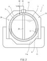
- the outer surface of the outer shell 4 need not be covered by the second heat insulator 8, and may be bare as shown in FIG. 2 . However, in this case, the heat insulation performance needs to be ensured by increasing the distance from the inner shell 3 to the outer shell 4. In contrast, when the outer surface of the outer shell 4 is covered by the second heat insulator 8 as in the embodiment described above, the distance from the inner shell 3 to the outer shell 4 and hence the diameter of the outer shell 4 can be smaller than when the outer surface of the outer shell 4 is not covered by the second heat insulator 8.
- the present modification is applicable also to second and third embodiments described below.
- FIG. 3 shows the liquefied gas carrier ship 1 including a double-shell tank 2B according to the second embodiment of the present invention.
- elements which are the same as those of the first embodiment are denoted by the same reference signs, and the descriptions given above for these elements are omitted.
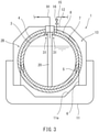
- the branch pipe 92 is not used to fill the space between the inner and outer shells 3 and 4 with the boil-off gas, but instead an upper portion of the inner shell 3 includes communication holes 31 allowing the space between the inner and outer shells 3 and 4 to communicate with the interior of the inner shell 3. There may be only one communication hole 31.
- the first heat insulator 7 is a foamed material.
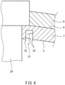
- each communication hole 31 in the present embodiment is defined by a communication pipe 32 joined to the inner shell 3 around the pipe tower 20.
- the communication pipe 32 is a straight pipe, and at least one projection 33 (two projections 33 in the example shown) that prevents the liquefied gas from leaking from the inner shell 3 into the space between the inner and outer shells 3 and 4 is disposed in the communication pipe 32.
- a discharge pipe 15 provided with an on-off valve 16 be connected to the outer shell 4 to allow the boil-off gas to be discharged out of the space between the inner and outer shells 3 and 4 in the event that the pressure in the space excessively increases.
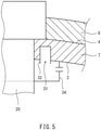
- an umbrella structure 34 that prevents the liquefied gas flowing from the inner shell 3 into the communication hole 31 is disposed in the inner shell 3.
- the communication pipe 32 includes through holes arranged in a matrix or zigzag pattern, and one end (lower end) of the communication pipe 32 that is located in the inner shell 3 is closed by a closure plate 35.
- the communication pipe 32 is an S-shaped pipe bent in an S shape. One end of the communication pipe 32 that is located in the inner shell 3 opens upward, and the other end located between the inner and outer shells 3 and 4 opens downward.
- the communication pipe 32 is a V-shaped pipe bent in a V-shape.
- One end of the communication pipe 32 that is located in the inner shell 3 opens obliquely downward, and the other end located between the inner and outer shells 3 and 4 opens obliquely upward.
- a membrane 36 permeable to the boil-off gas and impermeable to the liquefied gas is attached to the lower end of the communication pipe 32 which is a straight pipe.
- the membrane 36 is a porous ceramic membrane or a palladium membrane.
- the configuration shown in FIG. 10 is suitable for the case where the first heat insulator 7 is a granular material.
- the communication pipe 32 penetrates through the outer shell 4, and is bent at 180 degrees outside the outer shell 4 and connected to the outer shell 4.
- FIG. 11 shows the liquefied gas carrier ship 1 including a double-shell tank 2C according to the third embodiment of the present invention.
- elements which are the same as those of the first and second embodiments are denoted by the same reference signs, and the descriptions given above for these elements are omitted.
- the top portion of the inner shell 3 includes an opening 21 for providing a gap between the top portion of the inner shell 3 and the pipe tower 20, and the communication hole 31 is defined by the gap.
- a reinforcing ring 22 is joined to the inner shell 3 along the periphery of the opening 21.
- the inner diameter of the reinforcing ring 22 is larger than the diameter of the post portion of the pipe tower 20.
- a tubular partition plate 23 rises from the reinforcing ring 22, and an annular baffle plate 23a projecting radially inward is disposed at the upper end of the partition plate 23. Additionally, a tubular gas-permeable member (a metal mesh or porous plate) is located between the upper end of the partition plate 23 and the box portion of the pipe tower 20 (or optionally the outer shell 4).
- a tubular gas-permeable member a metal mesh or porous plate
- This configuration also allows the space between the inner and outer shells 3 and 4 to be filled with the boil-off gas.
- the double-shell tanks 2A to 2C need not be included in the liquefied gas carrier ship 1, and may be included in onshore facilities. Additionally, the space between the inner and outer shells 3 and 4 need not be packed with the first heat insulator 7, and may be free of any substances other than the boil-off gas.
Landscapes
- Engineering & Computer Science (AREA)
- Mechanical Engineering (AREA)
- General Engineering & Computer Science (AREA)
- Chemical & Material Sciences (AREA)
- Combustion & Propulsion (AREA)
- Ocean & Marine Engineering (AREA)
- Physics & Mathematics (AREA)
- Thermal Sciences (AREA)
- Filling Or Discharging Of Gas Storage Vessels (AREA)
Abstract
Description
- The present invention relates to a double-shell tank and a liquefied gas carrier ship including the double-shell tank.
- Double-shell tanks for liquefied gases such as LNG and liquefied hydrogen have been conventionally known. For example,
Patent Literature 1 discloses a spherical double-shell tank including an inner shell storing a liquefied gas and an outer shell enclosing the inner shell. In the double-shell tank, the space between the inner and outer shells is a vacuum, and a heat insulator is packed in the space between the inner and outer shells. - PTL 1:
Japanese Laid-Open Patent Application Publication No. H2-195099 - However, in the double-shell tank disclosed in
Patent Literature 1, the outer shell is subjected to a large force arising from the pressure difference between the vacuum inside the outer shell and the atmosphere outside the outer shell, and is thus required to have a significantly high strength. - It is therefore an object of the present invention to provide a double-shell tank that allows for a reduction in the strength required of the outer shell and a liquefied gas carrier ship including the double-shell tank.
- In order to solve the above problem, a double-shell tank of the present invention includes: a spherical inner shell storing a liquefied gas; and an outer shell enclosing the inner shell, wherein a space between the inner and outer shells is filled with a boil-off gas generated by evaporation of the liquefied gas.
- A liquefied gas carrier ship of the present invention includes a double-shell tank, the double shell tank including a spherical inner shell storing a liquefied gas and an outer shell enclosing the inner shell, wherein a space between the inner and outer shells is filled with a boil-off gas generated by evaporation of the liquefied gas.
- In the above configuration, the pressure in the space between the inner and outer shells can be made similar to the atmospheric pressure. Thus, the strength required of the outer shell can be reduced.
- The double-shell tank may further include: a gas delivery pipe through which the boil-off gas is delivered from the inner shell to another device; and a branch pipe branching from the gas delivery pipe and including a distal end opening into the space between the inner and outer shells. In the case where the double-shell tank with this configuration is mounted on a hull, leakage of the liquefied gas into the space between the inner and outer shells can be prevented in the event that sloshing of the liquefied gas occurs due to rocking of the hull.
- Alternatively, the inner shell may include a communication hole allowing the space between the inner and outer shells to communicate with an interior of the inner shell.
- The double-shell tank may further include a pipe tower extending from a top portion of the outer shell to a bottom of the inner shell, and the communication hole may be defined by a communication pipe joined to the inner shell around the pipe tower. Further, in the case where the double-shell tank with any one of the following
configurations 1 to 6 is mounted on a hull, leakage of the liquefied gas into the space between the inner and outer shells can be prevented in the event that sloshing of the liquefied gas occurs due to rocking of the hull. - Configuration 1: The communication pipe is a straight pipe, and at least one projection that prevents the liquefied gas from leaking from the inner shell into the space between the inner and outer shells is disposed in the communication pipe.
- Configuration 2: The communication pipe is a straight pipe, and an umbrella structure that prevents the liquefied gas from flowing from the inner shell into the communication hole is disposed in the inner shell.
- Configuration 3: The communication pipe is a straight pipe, the communication pipe includes through holes arranged in a matrix or zigzag pattern, and one end of the communication pipe is closed by a closure plate, the one end being located in the inner shell.
- Configuration 4: The communication pipe is an S-shaped pipe bent in an S-shape such that one end of the pipe opens upward and the other end of the pipe opens downward, the one end being located in the inner shell, the other end being located between the inner and outer shells.
- Configuration 5: The communication pipe is a V-shaped pipe bent in a V-shape such that one end of the pipe opens obliquely downward and the other end of the pipe opens obliquely upward, the one end being located in the inner shell, the other end being located between the inner and outer shells.
- Configuration 6: The communication pipe is a straight pipe, and a membrane permeable to the boil-off gas and impermeable to the liquefied gas is attached to one end of the communication pipe, the one end being located in the inner shell.
- Alternatively, the double-shell tank may further include a pipe tower extending from a top portion of the outer shell to a bottom of the inner shell, a top portion of the inner shell may include an opening for providing a gap between the top portion of the inner shell and the pipe tower, and the communication hole may be defined by the gap.
- For example, the double-shell tank may further include a heat insulator packed in the space between the inner and outer shells and covering an outer surface of the inner shell and an inner surface of the outer shell.
- The double-shell tank may further include a heat insulator covering an outer surface of the outer shell. In this configuration, the distance from the inner shell to the outer shell and hence the diameter of the outer shell can be smaller than in a configuration where the outer surface of the outer shell is not covered by the heat insulator.
- The present invention allows for a reduction in the strength required of an outer shell.
-
-
FIG. 1 is a cross-sectional view of a liquefied gas carrier ship including a double-shell tank according to a first embodiment of the present invention. -
FIG. 2 is a cross-sectional view of a liquefied gas carrier ship including a double-shell tank according to a modification of the first embodiment. -
FIG. 3 is a cross-sectional view of a liquefied gas carrier ship including a double-shell tank according to a second embodiment of the present invention. -
FIG. 4 is an enlarged view of a key part shown inFIG. 3 . -
FIG. 5 is an enlarged view of a key part of a double-shell tank according to a first modification of the second embodiment. -
FIG. 6 is an enlarged view of a key part of a double-shell tank according to a second modification of the second embodiment. -
FIG. 7 is an enlarged view of a key part of a double-shell tank according to a third modification of the second embodiment. -
FIG. 8 is an enlarged view of a key part of a double-shell tank according to a fourth modification of the second embodiment. -
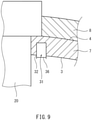
FIG. 9 is a cross-sectional view of a liquefied gas carrier ship including a double-shell tank according to a fifth modification of the second embodiment. -
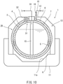
FIG. 10 is a cross-sectional view of a liquefied gas carrier ship including a double-shell tank according to a sixth modification of the second embodiment. -
FIG. 11 is a cross-sectional view of a liquefied gas carrier ship including a double-shell tank according to a third embodiment of the present invention. -
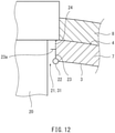
FIG. 12 is an enlarged view of a key part shown inFIG. 11 . -
FIG. 1 shows a liquefiedgas carrier ship 1 including a double-shell tank 2A according to a first embodiment of the present invention. The liquefiedgas carrier ship 1 includes, in addition to the double-shell tank 2A, ahull 11 on which the double-shell tank 2A is mounted and atank cover 12 forming aholding space 13 around the double-shell tank 2A together with thehull 11. - In the present embodiment, the
holding space 13 is filled with nitrogen gas. Theholding space 13 may be filled with dry air or exhaust gas of an engine for propulsion. - The double-
shell tank 2A includes aninner shell 3 storing a liquefied gas and anouter shell 4 enclosing theinner shell 3. For example, the liquefied gas is LNG, liquefied nitrogen, liquefied hydrogen, or liquefied helium. The double-shell tank 2A further includes a pipe tower (also referred to as "pump tower") 20 extending from the top portion of theouter shell 4 to the bottom of theinner shell 3. - The
inner shell 3 is spherical. Theinner shell 3 need not be spherically symmetric and may have a shape close to a spherically symmetric shape. For example, theinner shell 3 may have a shape differing from a spherically symmetric shape in that theinner shell 3 bulges upward and/or downward in the direction of 45 degrees with respect to the center of theinner shell 3. Alternatively, theinner shell 3 may have a shape with a short tubular element interposed between the upper and lower hemispheres. - In the present embodiment, the
outer shell 4 is also spherical. The center of theouter shell 4 coincides with the center of theinner shell 3. Like theinner shell 3, theouter shell 4 need not be spherically symmetric and may have a shape close to a spherically symmetric shape. For example, like theinner shell 3, theouter shell 4 may have a shape differing from a spherically symmetric shape in that theouter shell 4 bulges upward and/or downward in the direction of 45 degrees with respect to the center of theouter shell 4. Theouter shell 4 need not be spherical and may have any other shape. - The
pipe tower 20 includes a sealed box portion joined to the top portion of theouter shell 4 and a post portion extending downward from the box portion and penetrating through the top portion of theinner shell 3. For example, the post portion is in the shape of a hollow circular cylinder, and the part of the post portion that is located in theinner shell 3 includes through holes formed at suitable locations to allow communication between the inside and outside of the post portion. The post portion may be in the shape of a quadrangular prism. - Although not shown, a pump for pumping up the liquefied gas is disposed in a lower region inside the post portion of the
pipe tower 20. A liquid delivery pipe and an electricity pipe are connected to the pump, and the liquid delivery pipe and electricity pipe pass through the inside of the post portion of thepipe tower 20 and penetrate through the box portion of thepipe tower 20 to the outside of thepipe tower 20. - Further, the box portion of the
pipe tower 20 is penetrated also by agas delivery pipe 91. Thegas delivery pipe 91 serves to deliver a boil-off gas generated by evaporation of the liquefied gas stored in theinner shell 3 from theinner shell 3 to another device. The other device is, for example, the engine for propulsion, an engine for electricity generation, a reliquefaction device, or an atmospheric relief device. - A
first heat insulator 7 is packed in the space between the inner andouter shells first heat insulator 7 entirely covers the outer surface of theinner shell 3 and the inner surface of theouter shell 4. Further, the outer surface of theouter shell 4 is entirely covered by asecond heat insulator 8. - For example, the
first heat insulator 7 may be a foamed material made of a resin such as polyurethane (PU) or phenolic resin (PF), may be a granular material such as perlite or hollow glass spheres, or may be an inorganic fibrous material such as glass wool. - The
second heat insulator 8 is, for example, a foamed material made of a resin such as polyurethane or phenolic resin. As described above, the holdingspace 13 is filled with nitrogen gas. Thus, in the case where thesecond heat insulator 8 is a foamed material, the nitrogen gas enters thesecond heat insulator 8 from the holdingspace 13, and the internal pores of thesecond heat insulator 8 are filled with the nitrogen gas. Nitrogen gas may be fed to thesecond heat insulator 8 from a gas generator (not shown). In the case where the holdingspace 13 is filled with dry air, the internal pores of thesecond heat insulator 8 may also be filled with dry air. - The space between the inner and
outer shells outer shells - In the present embodiment, a
branch pipe 92 branches from thegas delivery pipe 91 described above. The distal end of thebranch pipe 92 opens into the space between the inner andouter shells gas delivery pipe 91 may be provided with various devices such as a compressor located upstream of the point of branching of thebranch pipe 92. Thebranch pipe 92 may be provided with devices such as a pressure regulation valve and a check valve. - The
outer shell 4 is supported by askirt 6 on afloor surface 11a of thehull 11, and theinner shell 3 is supported by askirt 5 on the inner circumferential surface of theouter shell 4. Theskirts skirt 6 is jointed to an equatorial portion of theouter shell 4, and the upper end of theskirt 5 is joined to an equatorial portion of theinner shell 3. - The structure for supporting the
outer shell 4 andinner shell 3 may be changed as appropriate. For example, theinner shell 3 may be suspended from theouter shell 4. - In the double-
shell tank 2A of the present embodiment, as described above, the pressure in the space between the inner andouter shells outer shell 4 can be reduced. - The outer surface of the
outer shell 4 need not be covered by thesecond heat insulator 8, and may be bare as shown inFIG. 2 . However, in this case, the heat insulation performance needs to be ensured by increasing the distance from theinner shell 3 to theouter shell 4. In contrast, when the outer surface of theouter shell 4 is covered by thesecond heat insulator 8 as in the embodiment described above, the distance from theinner shell 3 to theouter shell 4 and hence the diameter of theouter shell 4 can be smaller than when the outer surface of theouter shell 4 is not covered by thesecond heat insulator 8. The present modification is applicable also to second and third embodiments described below. -
FIG. 3 shows the liquefiedgas carrier ship 1 including a double-shell tank 2B according to the second embodiment of the present invention. In the present embodiment, elements which are the same as those of the first embodiment are denoted by the same reference signs, and the descriptions given above for these elements are omitted. - In the present embodiment, the
branch pipe 92 is not used to fill the space between the inner andouter shells inner shell 3 includes communication holes 31 allowing the space between the inner andouter shells inner shell 3. There may be only onecommunication hole 31. In the present embodiment, thefirst heat insulator 7 is a foamed material. - Specifically, as shown in
FIG. 4 , eachcommunication hole 31 in the present embodiment is defined by acommunication pipe 32 joined to theinner shell 3 around thepipe tower 20. Thecommunication pipe 32 is a straight pipe, and at least one projection 33 (twoprojections 33 in the example shown) that prevents the liquefied gas from leaking from theinner shell 3 into the space between the inner andouter shells communication pipe 32. - In such a configuration, leakage of the liquefied gas into the space between the inner and
outer shells hull 11. - In the present embodiment, it is desirable that a
discharge pipe 15 provided with an on-offvalve 16 be connected to theouter shell 4 to allow the boil-off gas to be discharged out of the space between the inner andouter shells - The effect similar to that of the above embodiment can be achieved by configurations shown in
FIGS. 5 to 10 . - In the configuration shown in
FIG. 5 , anumbrella structure 34 that prevents the liquefied gas flowing from theinner shell 3 into thecommunication hole 31 is disposed in theinner shell 3. - In the configuration shown in
FIG. 6 , thecommunication pipe 32 includes through holes arranged in a matrix or zigzag pattern, and one end (lower end) of thecommunication pipe 32 that is located in theinner shell 3 is closed by aclosure plate 35. - In the configuration shown in
FIG. 7 , thecommunication pipe 32 is an S-shaped pipe bent in an S shape. One end of thecommunication pipe 32 that is located in theinner shell 3 opens upward, and the other end located between the inner andouter shells - In the configuration shown in
FIG. 8 , thecommunication pipe 32 is a V-shaped pipe bent in a V-shape. One end of thecommunication pipe 32 that is located in theinner shell 3 opens obliquely downward, and the other end located between the inner andouter shells - In the configuration shown in
FIG. 9 , amembrane 36 permeable to the boil-off gas and impermeable to the liquefied gas is attached to the lower end of thecommunication pipe 32 which is a straight pipe. For example, themembrane 36 is a porous ceramic membrane or a palladium membrane. - The configuration shown in
FIG. 10 is suitable for the case where thefirst heat insulator 7 is a granular material. In the configuration shown inFIG. 10 , thecommunication pipe 32 penetrates through theouter shell 4, and is bent at 180 degrees outside theouter shell 4 and connected to theouter shell 4. -
FIG. 11 shows the liquefiedgas carrier ship 1 including a double-shell tank 2C according to the third embodiment of the present invention. In the present embodiment, elements which are the same as those of the first and second embodiments are denoted by the same reference signs, and the descriptions given above for these elements are omitted. - In the present embodiment, the top portion of the
inner shell 3 includes an opening 21 for providing a gap between the top portion of theinner shell 3 and thepipe tower 20, and thecommunication hole 31 is defined by the gap. - Specifically, as shown in
FIG. 12 , a reinforcingring 22 is joined to theinner shell 3 along the periphery of the opening 21. The inner diameter of the reinforcingring 22 is larger than the diameter of the post portion of thepipe tower 20. - A
tubular partition plate 23 rises from the reinforcingring 22, and anannular baffle plate 23a projecting radially inward is disposed at the upper end of thepartition plate 23. Additionally, a tubular gas-permeable member (a metal mesh or porous plate) is located between the upper end of thepartition plate 23 and the box portion of the pipe tower 20 (or optionally the outer shell 4). - This configuration also allows the space between the inner and
outer shells - The present invention is not limited to the embodiments described above, and various modifications can be made without departing from the gist of the present invention.
- For example, the double-
shell tanks 2A to 2C need not be included in the liquefiedgas carrier ship 1, and may be included in onshore facilities. Additionally, the space between the inner andouter shells first heat insulator 7, and may be free of any substances other than the boil-off gas. -
- 1
- liquefied gas carrier ship
- 2
- double-shell tank
- 20
- pipe tower
- 21
- opening
- 3
- inner shell
- 31
- communication hole
- 32
- communication pipe
- 33
- projection
- 34
- umbrella structure
- 35
- closure plate
- 36
- membrane
- 4
- outer shell
- 7, 8
- heat insulator
- 91
- gas delivery pipe
- 92
- branch pipe
Claims (14)
- A double-shell tank comprising:a spherical inner shell storing a liquefied gas; andan outer shell enclosing the inner shell, whereina space between the inner and outer shells is filled with a boil-off gas generated by evaporation of the liquefied gas.
- The double-shell tank according to claim 1, further comprising:a gas delivery pipe through which the boil-off gas is delivered from the inner shell to another device; anda branch pipe branching from the gas delivery pipe and including a distal end opening into the space between the inner and outer shells.
- The double-shell tank according to claim 1, wherein the inner shell includes a communication hole allowing the space between the inner and outer shells to communicate with an interior of the inner shell.
- The double-shell tank according to claim 3, further comprising a pipe tower extending from a top portion of the outer shell to a bottom of the inner shell, wherein
the communication hole is defined by a communication pipe joined to the inner shell around the pipe tower. - The double-shell tank according to claim 4, whereinthe communication pipe is a straight pipe, andat least one projection that prevents the liquefied gas from leaking from the inner shell into the space between the inner and outer shells is disposed in the communication pipe.
- The double-shell tank according to claim 4, whereinthe communication pipe is a straight pipe, andan umbrella structure that prevents the liquefied gas from flowing from the inner shell into the communication hole is disposed in the inner shell.
- The double-shell tank according to claim 4, whereinthe communication pipe is a straight pipe,the communication pipe includes through holes arranged in a matrix or zigzag pattern, andone end of the communication pipe is closed by a closure plate, the one end being located in the inner shell.
- The double-shell tank according to claim 4, wherein the communication pipe is an S-shaped pipe bent in an S-shape such that one end of the pipe opens upward and the other end of the pipe opens downward, the one end being located in the inner shell, the other end being located between the inner and outer shells.
- The double-shell tank according to claim 4, wherein the communication pipe is a V-shaped pipe bent in a V-shape such that one end of the pipe opens obliquely downward and the other end of the pipe opens obliquely upward, the one end being located in the inner shell, the other end being located between the inner and outer shells.
- The double-shell tank according to claim 4, whereinthe communication pipe is a straight pipe, anda membrane permeable to the boil-off gas and impermeable to the liquefied gas is attached to one end of the communication pipe, the one end being located in the inner shell.
- The double-shell tank according to claim 3, further comprising a pipe tower extending from a top portion of the outer shell to a bottom of the inner shell, whereina top portion of the inner shell includes an opening for providing a gap between the top portion of the inner shell and the pipe tower, andthe communication hole is defined by the gap.
- The double-shell tank according to any one of claims 1 to 11, further comprising a heat insulator packed in the space between the inner and outer shells and covering an outer surface of the inner shell and an inner surface of the outer shell.
- The double-shell tank according to any one of claims 1 to 12, further comprising a heat insulator covering an outer surface of the outer shell.
- A liquefied gas carrier ship comprising a double-shell tank,the double shell tank including a spherical inner shell storing a liquefied gas and an outer shell enclosing the inner shell, whereina space between the inner and outer shells is filled with a boil-off gas generated by evaporation of the liquefied gas.
Applications Claiming Priority (1)
| Application Number | Priority Date | Filing Date | Title |
|---|---|---|---|
| PCT/JP2019/015227 WO2020202578A1 (en) | 2019-04-05 | 2019-04-05 | Double-shell tank and liquefied gas carrier |
Publications (3)
| Publication Number | Publication Date |
|---|---|
| EP3951243A1 true EP3951243A1 (en) | 2022-02-09 |
| EP3951243A4 EP3951243A4 (en) | 2022-11-16 |
| EP3951243B1 EP3951243B1 (en) | 2026-07-08 |
Family
ID=72667298
Family Applications (1)
| Application Number | Title | Priority Date | Filing Date |
|---|---|---|---|
| EP19922738.0A Active EP3951243B1 (en) | 2019-04-05 | 2019-04-05 | Double-shell tank and liquefied gas carrier ship |
Country Status (5)
| Country | Link |
|---|---|
| EP (1) | EP3951243B1 (en) |
| JP (1) | JP7365400B2 (en) |
| KR (1) | KR102626816B1 (en) |
| CN (1) | CN113661355B (en) |
| WO (1) | WO2020202578A1 (en) |
Cited By (1)
| Publication number | Priority date | Publication date | Assignee | Title |
|---|---|---|---|---|
| NO20221390A1 (en) * | 2022-12-22 | 2024-06-24 | Moss Maritime As | Liquified gas storage tank |
Families Citing this family (11)
| Publication number | Priority date | Publication date | Assignee | Title |
|---|---|---|---|---|
| JP7675546B2 (en) | 2021-03-31 | 2025-05-13 | 川崎重工業株式会社 | Multi-shell tank, ship and gas pressure adjustment method |
| JP7749336B2 (en) * | 2021-03-31 | 2025-10-06 | 川崎重工業株式会社 | Gas Processing Systems and Ships |
| JP7877030B2 (en) * | 2022-03-23 | 2026-06-22 | 川崎重工業株式会社 | Cooling down methods for liquefied gas storage tanks |
| JP7837189B2 (en) * | 2022-03-23 | 2026-03-30 | 川崎重工業株式会社 | Cooling down methods for liquefied gas storage tanks |
| JP7837190B2 (en) * | 2022-03-23 | 2026-03-30 | 川崎重工業株式会社 | Methods for cooling down liquefied gas storage tanks |
| CN118946499A (en) * | 2022-04-13 | 2024-11-12 | 川崎重工业株式会社 | Liquefied gas storage tank |
| JP7793807B2 (en) * | 2022-09-30 | 2026-01-05 | 川崎重工業株式会社 | Multi-hull tanks and ships |
| CN119183511A (en) * | 2022-09-30 | 2024-12-24 | 川崎重工业株式会社 | Multilayer shell tank |
| KR20250065662A (en) | 2022-09-30 | 2025-05-13 | 카와사키 주코교 카부시키 카이샤 | Liquid hydrogen tank and its operation method |
| CN120615148A (en) | 2023-02-08 | 2025-09-09 | 川崎重工业株式会社 | Liquid hydrogen storage equipment, floating structure, and method for supplying gas between tanks of multi-layer shell tanks |
| WO2025158516A1 (en) * | 2024-01-23 | 2025-07-31 | 川崎重工業株式会社 | Structure provided with closed section and gas replacement method |
Family Cites Families (14)
| Publication number | Priority date | Publication date | Assignee | Title |
|---|---|---|---|---|
| JPS58156800A (en) * | 1982-03-09 | 1983-09-17 | Jgc Corp | Double-shell low-temperature tank |
| JP2676754B2 (en) * | 1988-01-14 | 1997-11-17 | ヤマハ株式会社 | Automatic performance recorder |
| JPH02195099A (en) | 1989-01-24 | 1990-08-01 | Mitsubishi Heavy Ind Ltd | Adiabatic supporting device of double spherical tank |
| JPH1182889A (en) * | 1997-09-10 | 1999-03-26 | I H I Plantec:Kk | Vertical insulated cryogenic tank |
| JP4431842B2 (en) * | 1998-03-31 | 2010-03-17 | 株式会社石井鐵工所 | Inner tank support structure of double shell spherical storage tank |
| JP2004028238A (en) | 2002-06-26 | 2004-01-29 | Mitsubishi Heavy Ind Ltd | Tank |
| DE102007011530A1 (en) * | 2007-03-09 | 2008-09-11 | Bayerische Motoren Werke Aktiengesellschaft | Method for filling a pressure accumulator provided for a cryogenic storage medium, in particular hydrogen |
| WO2012053704A1 (en) * | 2010-10-22 | 2012-04-26 | 대우조선해양 주식회사 | Storage container for liquefied natural gas |
| US9587787B2 (en) * | 2013-04-23 | 2017-03-07 | Kawasaki Jukogyo Kabushiki Kaisha | Support structure of ship tank, and liquefied gas carrier |
| KR101865210B1 (en) * | 2013-06-21 | 2018-06-07 | 카와사키 주코교 카부시키 카이샤 | Liquefied gas-storing tank and liquefied gas transport vessel |
| JP6418942B2 (en) | 2014-12-26 | 2018-11-07 | 川崎重工業株式会社 | Liquefied gas carrier |
| CN205191196U (en) * | 2015-11-04 | 2016-04-27 | 河南开利空分设备集团有限公司 | Low temperature liquid tank device of heat preservation, safety |
| KR102593666B1 (en) * | 2015-12-22 | 2023-10-24 | 쉘 인터내셔날 리써취 마트샤피지 비.브이. | Ship containment system for liquified gases |
| JP6909634B2 (en) * | 2017-05-19 | 2021-07-28 | 川崎重工業株式会社 | Cryogenic gas storage tank |
-
2019
- 2019-04-05 WO PCT/JP2019/015227 patent/WO2020202578A1/en not_active Ceased
- 2019-04-05 JP JP2021511074A patent/JP7365400B2/en active Active
- 2019-04-05 KR KR1020217033824A patent/KR102626816B1/en active Active
- 2019-04-05 CN CN201980095113.5A patent/CN113661355B/en active Active
- 2019-04-05 EP EP19922738.0A patent/EP3951243B1/en active Active
Cited By (2)
| Publication number | Priority date | Publication date | Assignee | Title |
|---|---|---|---|---|
| NO20221390A1 (en) * | 2022-12-22 | 2024-06-24 | Moss Maritime As | Liquified gas storage tank |
| NO348617B1 (en) * | 2022-12-22 | 2025-03-31 | Moss Maritime As | A liquefied gas storage tank and a method for manufacturing said tank |
Also Published As
| Publication number | Publication date |
|---|---|
| EP3951243A4 (en) | 2022-11-16 |
| KR102626816B1 (en) | 2024-01-18 |
| WO2020202578A1 (en) | 2020-10-08 |
| JPWO2020202578A1 (en) | 2020-10-08 |
| KR20210141627A (en) | 2021-11-23 |
| CN113661355B (en) | 2023-03-28 |
| CN113661355A (en) | 2021-11-16 |
| JP7365400B2 (en) | 2023-10-19 |
| EP3951243B1 (en) | 2026-07-08 |
Similar Documents
| Publication | Publication Date | Title |
|---|---|---|
| CN113661355B (en) | Double-shell tank and liquefied gas carrying ship | |
| EP3950536A1 (en) | Liquefied gas tank and liquefied gas carrying vessel | |
| US20060236789A1 (en) | Container for holding a cryogenic fuel | |
| EP3904196A1 (en) | Ship | |
| KR102707025B1 (en) | Pump Tower of Liquefied Gas Storage Tank | |
| US20140166662A1 (en) | Suspension System for a Cryogenic Vessel | |
| KR102782464B1 (en) | shipping | |
| KR102340889B1 (en) | Double shell tanks and liquefied gas carriers | |
| EP3951244B1 (en) | Liquefied gas storage structure and liquefied gas carrier ship | |
| KR102782178B1 (en) | Pump Tower Supporting Structure of Liquefied Gas Storage Tank | |
| EP4159610A1 (en) | Vent mast | |
| KR102729240B1 (en) | Pump Tower of Liquefied Gas Storage Tank | |
| KR20210071317A (en) | Pump Tower of Liquefied Gas Storage Tank including Spraying Pipe | |
| EP4317764A1 (en) | Multi-shell tank and vessel | |
| KR102729241B1 (en) | Pump Tower of Liquefied Gas Storage Tank | |
| KR102754070B1 (en) | Pump Tower of Liquefied Gas Storage Tank | |
| KR102728680B1 (en) | Pump Tower of Liquefied Gas Storage Tank | |
| KR102728682B1 (en) | Pump Tower Supporting Structure of Liquefied Gas Storage Tank | |
| KR102694833B1 (en) | Cool-down Method of Liquefied Gas Storage Tank including Filling Pipe having Double Pipe Structure | |
| JPH0510503Y2 (en) | ||
| KR20250179184A (en) | Pump tower base support for liquefied gas storage tank | |
| JP2020034138A (en) | Tube opening protection structure | |
| KR20250065663A (en) | Multi-angle tank |
Legal Events
| Date | Code | Title | Description |
|---|---|---|---|
| STAA | Information on the status of an ep patent application or granted ep patent |
Free format text: STATUS: THE INTERNATIONAL PUBLICATION HAS BEEN MADE |
|
| PUAI | Public reference made under article 153(3) epc to a published international application that has entered the european phase |
Free format text: ORIGINAL CODE: 0009012 |
|
| STAA | Information on the status of an ep patent application or granted ep patent |
Free format text: STATUS: REQUEST FOR EXAMINATION WAS MADE |
|
| 17P | Request for examination filed |
Effective date: 20211105 |
|
| AK | Designated contracting states |
Kind code of ref document: A1 Designated state(s): AL AT BE BG CH CY CZ DE DK EE ES FI FR GB GR HR HU IE IS IT LI LT LU LV MC MK MT NL NO PL PT RO RS SE SI SK SM TR |
|
| DAV | Request for validation of the european patent (deleted) | ||
| DAX | Request for extension of the european patent (deleted) | ||
| A4 | Supplementary search report drawn up and despatched |
Effective date: 20221019 |
|
| RIC1 | Information provided on ipc code assigned before grant |
Ipc: F17C 3/02 20060101ALI20221013BHEP Ipc: B63B 25/16 20060101ALI20221013BHEP Ipc: F17C 13/00 20060101AFI20221013BHEP |
|
| GRAP | Despatch of communication of intention to grant a patent |
Free format text: ORIGINAL CODE: EPIDOSNIGR1 |
|
| STAA | Information on the status of an ep patent application or granted ep patent |
Free format text: STATUS: GRANT OF PATENT IS INTENDED |
|
| INTG | Intention to grant announced |
Effective date: 20260318 |
|
| GRAS | Grant fee paid |
Free format text: ORIGINAL CODE: EPIDOSNIGR3 |
|
| GRAA | (expected) grant |
Free format text: ORIGINAL CODE: 0009210 |
|
| STAA | Information on the status of an ep patent application or granted ep patent |
Free format text: STATUS: THE PATENT HAS BEEN GRANTED |
|
| AK | Designated contracting states |
Kind code of ref document: B1 Designated state(s): AL AT BE BG CH CY CZ DE DK EE ES FI FR GB GR HR HU IE IS IT LI LT LU LV MC MK MT NL NO PL PT RO RS SE SI SK SM TR |
|
| REG | Reference to a national code |
Ref country code: CH Ref legal event code: F10 Free format text: ST27 STATUS EVENT CODE: U-0-0-F10-F00 (AS PROVIDED BY THE NATIONAL OFFICE) Effective date: 20260708 Ref country code: GB Ref legal event code: FG4D |
|
| REG | Reference to a national code |
Ref country code: DE Ref legal event code: R096 Ref document number: 602019086446 Country of ref document: DE |
|
| REG | Reference to a national code |
Ref country code: IE Ref legal event code: FG4D |