EP3950965A1 - Method for heating up hearth of blast furnace, and burner lance used for same - Google Patents
Method for heating up hearth of blast furnace, and burner lance used for same Download PDFInfo
- Publication number
- EP3950965A1 EP3950965A1 EP20777620.4A EP20777620A EP3950965A1 EP 3950965 A1 EP3950965 A1 EP 3950965A1 EP 20777620 A EP20777620 A EP 20777620A EP 3950965 A1 EP3950965 A1 EP 3950965A1
- Authority
- EP
- European Patent Office
- Prior art keywords
- burner lance
- furnace
- cap
- heating
- gas
- Prior art date
- Legal status (The legal status is an assumption and is not a legal conclusion. Google has not performed a legal analysis and makes no representation as to the accuracy of the status listed.)
- Pending
Links
- 238000010438 heat treatment Methods 0.000 title claims abstract description 84
- 238000000034 method Methods 0.000 title claims abstract description 69
- 238000007664 blowing Methods 0.000 claims abstract description 36
- 238000003780 insertion Methods 0.000 claims abstract description 19
- 230000037431 insertion Effects 0.000 claims abstract description 19
- 239000012768 molten material Substances 0.000 claims description 48
- 238000001816 cooling Methods 0.000 claims description 21
- 238000002844 melting Methods 0.000 claims description 13
- 230000008018 melting Effects 0.000 claims description 13
- 238000007254 oxidation reaction Methods 0.000 claims description 6
- 230000001590 oxidative effect Effects 0.000 claims description 6
- 238000003466 welding Methods 0.000 claims description 3
- 239000007789 gas Substances 0.000 description 79
- 229910000805 Pig iron Inorganic materials 0.000 description 13
- 238000010586 diagram Methods 0.000 description 12
- 239000000463 material Substances 0.000 description 12
- 239000002893 slag Substances 0.000 description 12
- 239000000571 coke Substances 0.000 description 10
- IJGRMHOSHXDMSA-UHFFFAOYSA-N Atomic nitrogen Chemical compound N#N IJGRMHOSHXDMSA-UHFFFAOYSA-N 0.000 description 7
- 230000000903 blocking effect Effects 0.000 description 7
- 238000007599 discharging Methods 0.000 description 7
- 238000002485 combustion reaction Methods 0.000 description 5
- 238000009434 installation Methods 0.000 description 5
- QVGXLLKOCUKJST-UHFFFAOYSA-N atomic oxygen Chemical compound [O] QVGXLLKOCUKJST-UHFFFAOYSA-N 0.000 description 4
- 239000003245 coal Substances 0.000 description 4
- 239000001301 oxygen Substances 0.000 description 4
- 229910052760 oxygen Inorganic materials 0.000 description 4
- 229910001873 dinitrogen Inorganic materials 0.000 description 3
- 230000000630 rising effect Effects 0.000 description 3
- XLYOFNOQVPJJNP-UHFFFAOYSA-N water Substances O XLYOFNOQVPJJNP-UHFFFAOYSA-N 0.000 description 3
- 229910001018 Cast iron Inorganic materials 0.000 description 2
- XEEYBQQBJWHFJM-UHFFFAOYSA-N Iron Chemical compound [Fe] XEEYBQQBJWHFJM-UHFFFAOYSA-N 0.000 description 2
- 238000006243 chemical reaction Methods 0.000 description 2
- 230000000052 comparative effect Effects 0.000 description 2
- 230000000694 effects Effects 0.000 description 2
- 238000004519 manufacturing process Methods 0.000 description 2
- 239000002184 metal Substances 0.000 description 2
- 229910052751 metal Inorganic materials 0.000 description 2
- 229910052757 nitrogen Inorganic materials 0.000 description 2
- 238000011084 recovery Methods 0.000 description 2
- 230000032683 aging Effects 0.000 description 1
- 239000002801 charged material Substances 0.000 description 1
- 239000004927 clay Substances 0.000 description 1
- 239000000567 combustion gas Substances 0.000 description 1
- 238000007796 conventional method Methods 0.000 description 1
- 239000002826 coolant Substances 0.000 description 1
- 230000003247 decreasing effect Effects 0.000 description 1
- 238000001035 drying Methods 0.000 description 1
- 239000000446 fuel Substances 0.000 description 1
- 239000002737 fuel gas Substances 0.000 description 1
- 239000011261 inert gas Substances 0.000 description 1
- 229910052742 iron Inorganic materials 0.000 description 1
- 239000000155 melt Substances 0.000 description 1
- 239000000203 mixture Substances 0.000 description 1
- 238000011160 research Methods 0.000 description 1
- 238000012546 transfer Methods 0.000 description 1
Images


Classifications
-
- C—CHEMISTRY; METALLURGY
- C21—METALLURGY OF IRON
- C21B—MANUFACTURE OF IRON OR STEEL
- C21B5/00—Making pig-iron in the blast furnace
- C21B5/001—Injecting additional fuel or reducing agents
-
- F—MECHANICAL ENGINEERING; LIGHTING; HEATING; WEAPONS; BLASTING
- F27—FURNACES; KILNS; OVENS; RETORTS
- F27B—FURNACES, KILNS, OVENS, OR RETORTS IN GENERAL; OPEN SINTERING OR LIKE APPARATUS
- F27B1/00—Shaft or like vertical or substantially vertical furnaces
- F27B1/08—Shaft or like vertical or substantially vertical furnaces heated otherwise than by solid fuel mixed with charge
-
- C—CHEMISTRY; METALLURGY
- C21—METALLURGY OF IRON
- C21B—MANUFACTURE OF IRON OR STEEL
- C21B9/00—Stoves for heating the blast in blast furnaces
- C21B9/08—Iron hot-blast stoves
-
- C—CHEMISTRY; METALLURGY
- C21—METALLURGY OF IRON
- C21B—MANUFACTURE OF IRON OR STEEL
- C21B7/00—Blast furnaces
- C21B7/12—Opening or sealing the tap holes
-
- C—CHEMISTRY; METALLURGY
- C21—METALLURGY OF IRON
- C21B—MANUFACTURE OF IRON OR STEEL
- C21B7/00—Blast furnaces
- C21B7/16—Tuyéres
-
- C—CHEMISTRY; METALLURGY
- C21—METALLURGY OF IRON
- C21B—MANUFACTURE OF IRON OR STEEL
- C21B7/00—Blast furnaces
- C21B7/16—Tuyéres
- C21B7/163—Blowpipe assembly
-
- C—CHEMISTRY; METALLURGY
- C21—METALLURGY OF IRON
- C21B—MANUFACTURE OF IRON OR STEEL
- C21B7/00—Blast furnaces
- C21B7/24—Test rods or other checking devices
-
- F—MECHANICAL ENGINEERING; LIGHTING; HEATING; WEAPONS; BLASTING
- F23—COMBUSTION APPARATUS; COMBUSTION PROCESSES
- F23D—BURNERS
- F23D14/00—Burners for combustion of a gas, e.g. of a gas stored under pressure as a liquid
- F23D14/20—Non-premix gas burners, i.e. in which gaseous fuel is mixed with combustion air on arrival at the combustion zone
-
- F—MECHANICAL ENGINEERING; LIGHTING; HEATING; WEAPONS; BLASTING
- F27—FURNACES; KILNS; OVENS; RETORTS
- F27B—FURNACES, KILNS, OVENS, OR RETORTS IN GENERAL; OPEN SINTERING OR LIKE APPARATUS
- F27B1/00—Shaft or like vertical or substantially vertical furnaces
-
- F—MECHANICAL ENGINEERING; LIGHTING; HEATING; WEAPONS; BLASTING
- F27—FURNACES; KILNS; OVENS; RETORTS
- F27B—FURNACES, KILNS, OVENS, OR RETORTS IN GENERAL; OPEN SINTERING OR LIKE APPARATUS
- F27B1/00—Shaft or like vertical or substantially vertical furnaces
- F27B1/10—Details, accessories, or equipment peculiar to furnaces of these types
-
- F—MECHANICAL ENGINEERING; LIGHTING; HEATING; WEAPONS; BLASTING
- F27—FURNACES; KILNS; OVENS; RETORTS
- F27D—DETAILS OR ACCESSORIES OF FURNACES, KILNS, OVENS, OR RETORTS, IN SO FAR AS THEY ARE OF KINDS OCCURRING IN MORE THAN ONE KIND OF FURNACE
- F27D99/00—Subject matter not provided for in other groups of this subclass
- F27D99/0001—Heating elements or systems
- F27D99/0033—Heating elements or systems using burners
-
- C—CHEMISTRY; METALLURGY
- C21—METALLURGY OF IRON
- C21B—MANUFACTURE OF IRON OR STEEL
- C21B7/00—Blast furnaces
- C21B7/12—Opening or sealing the tap holes
- C21B7/125—Refractory plugging mass
-
- C—CHEMISTRY; METALLURGY
- C21—METALLURGY OF IRON
- C21C—PROCESSING OF PIG-IRON, e.g. REFINING, MANUFACTURE OF WROUGHT-IRON OR STEEL; TREATMENT IN MOLTEN STATE OF FERROUS ALLOYS
- C21C5/00—Manufacture of carbon-steel, e.g. plain mild steel, medium carbon steel or cast steel or stainless steel
- C21C5/28—Manufacture of steel in the converter
- C21C5/42—Constructional features of converters
- C21C5/46—Details or accessories
- C21C5/4606—Lances or injectors
-
- C—CHEMISTRY; METALLURGY
- C21—METALLURGY OF IRON
- C21C—PROCESSING OF PIG-IRON, e.g. REFINING, MANUFACTURE OF WROUGHT-IRON OR STEEL; TREATMENT IN MOLTEN STATE OF FERROUS ALLOYS
- C21C5/00—Manufacture of carbon-steel, e.g. plain mild steel, medium carbon steel or cast steel or stainless steel
- C21C5/28—Manufacture of steel in the converter
- C21C5/42—Constructional features of converters
- C21C5/46—Details or accessories
- C21C5/4653—Tapholes; Opening or plugging thereof
-
- F—MECHANICAL ENGINEERING; LIGHTING; HEATING; WEAPONS; BLASTING
- F23—COMBUSTION APPARATUS; COMBUSTION PROCESSES
- F23D—BURNERS
- F23D2214/00—Cooling
-
- F—MECHANICAL ENGINEERING; LIGHTING; HEATING; WEAPONS; BLASTING
- F27—FURNACES; KILNS; OVENS; RETORTS
- F27D—DETAILS OR ACCESSORIES OF FURNACES, KILNS, OVENS, OR RETORTS, IN SO FAR AS THEY ARE OF KINDS OCCURRING IN MORE THAN ONE KIND OF FURNACE
- F27D1/00—Casings; Linings; Walls; Roofs
- F27D2001/0079—Means to assemble at least two parts of a furnace or of any device or accessory associated to its use
-
- F—MECHANICAL ENGINEERING; LIGHTING; HEATING; WEAPONS; BLASTING
- F27—FURNACES; KILNS; OVENS; RETORTS
- F27D—DETAILS OR ACCESSORIES OF FURNACES, KILNS, OVENS, OR RETORTS, IN SO FAR AS THEY ARE OF KINDS OCCURRING IN MORE THAN ONE KIND OF FURNACE
- F27D99/00—Subject matter not provided for in other groups of this subclass
- F27D99/0001—Heating elements or systems
- F27D99/0033—Heating elements or systems using burners
- F27D2099/0036—Heating elements or systems using burners immersed in the charge
-
- F—MECHANICAL ENGINEERING; LIGHTING; HEATING; WEAPONS; BLASTING
- F27—FURNACES; KILNS; OVENS; RETORTS
- F27D—DETAILS OR ACCESSORIES OF FURNACES, KILNS, OVENS, OR RETORTS, IN SO FAR AS THEY ARE OF KINDS OCCURRING IN MORE THAN ONE KIND OF FURNACE
- F27D99/00—Subject matter not provided for in other groups of this subclass
- F27D99/0001—Heating elements or systems
- F27D99/0033—Heating elements or systems using burners
- F27D2099/0038—Heating elements or systems using burners removable
-
- F—MECHANICAL ENGINEERING; LIGHTING; HEATING; WEAPONS; BLASTING
- F27—FURNACES; KILNS; OVENS; RETORTS
- F27D—DETAILS OR ACCESSORIES OF FURNACES, KILNS, OVENS, OR RETORTS, IN SO FAR AS THEY ARE OF KINDS OCCURRING IN MORE THAN ONE KIND OF FURNACE
- F27D99/00—Subject matter not provided for in other groups of this subclass
- F27D99/0001—Heating elements or systems
- F27D2099/0058—Means for heating the charge locally
-
- F—MECHANICAL ENGINEERING; LIGHTING; HEATING; WEAPONS; BLASTING
- F27—FURNACES; KILNS; OVENS; RETORTS
- F27D—DETAILS OR ACCESSORIES OF FURNACES, KILNS, OVENS, OR RETORTS, IN SO FAR AS THEY ARE OF KINDS OCCURRING IN MORE THAN ONE KIND OF FURNACE
- F27D99/00—Subject matter not provided for in other groups of this subclass
- F27D99/0001—Heating elements or systems
- F27D2099/006—Auxiliary heating, e.g. in special conditions or at special times
Definitions
- the present invention relates to a method of heating up a furnace bottom used for heating up a content on the furnace bottom of a blast furnace and thereafter starting blast, and to a burner lance used in the method.
- a blast furnace is a facility that heats up, reduces, and melts iron ore with high temperature reduction gas generated by the reaction between high temperature air and oxygen blown from a tuyere zone and coke and pulverized coal, and produces pig iron and slag from a tap hole provided in a lower part of a tuyere.
- a normal operation of the blast furnace where the reaction heat in the furnace and the heat supply from the tuyere are balanced, a stable operation of the blast furnace is possible.
- it is necessary to stop blast into the blast furnace due to operation trouble and facility trouble of the blast furnace, and production adjustment.
- the furnace heat a temperature of a charged material and a molten material in the furnace (hereinafter referred to as the furnace heat) falls, due to heat removal from a furnace body / a furnace bottom, suction of air from the tuyere, and the like.
- a conventional method involves increasing the coke ratio in the furnace before the blast stoppage and, without immediately blowing pulverized coal after the blast, raising the temperature (heat compensation) until pulverized coal blowing can be started.
- the charged coke ratio is reduced after confirming the stable discharging of the molten pig iron slag. Therefore, letting the blast furnace rest leads to increase in the use rate of coke, the price of which is more expensive compared with pulverized coal.
- Patent Literature 1 a method of starting blast into a blast furnace that can be started up in a short time from a long-time blast stoppage, by installing a burner in a tap hole provided in the furnace bottom of the blast furnace to burn fuel, and efficiently heating up the furnace bottom, and a burner for furnace bottom temperature rising have been proposed.
- Patent Literature 1 Japanese Patent Laid-Open No. 2016-30833
- An object of the present invention is to propose a method of heating up a furnace bottom that can, when heating is performed with a lance (hereinafter generally referred to as a burner lance) having a function of blowing in combustion-supporting gas for heating up a burner provided in a tap hole and the furnace bottom at the time of startup from blast furnace stoppage or the like, eliminate damage to the burner lance, and that can recover the furnace heat and the operation rate at early stage, and a burner lance used in the method are proposed.
- a lance hereinafter generally referred to as a burner lance
- a first aspect of the present invention is a method of heating up a furnace bottom for heating up the furnace bottom by a burner lance provided in a tap hole of the furnace bottom of a blast furnace, the method including a step of opening, in the tap hole, a burner lance insertion hole having a diameter larger than a diameter of the burner lance so as to penetrate into the furnace, a step of installing the burner lance in the opened burner lance insertion hole, a step of filling a gap between the installed burner lance and a furnace exterior side of the tap hole with a refractory, and a step of blowing in gas for heating into the furnace from the burner lance to heat up the furnace bottom.
- a second aspect of the present invention is a method of heating up a furnace bottom for heating up the furnace bottom by a burner lance provided in a tap hole of the furnace bottom of a blast furnace, the method including a step of opening, in the tap hole, a hole larger than a diameter of the burner lance so as to penetrate into the furnace, a step of solidifying a molten material that comes out from the opened hole, a step of opening a burner lance insertion hole having a diameter larger than the diameter of the burner lance in the solidified molten material so as not to penetrate into the furnace, a step of installing the burner lance in the opened burner lance insertion hole, a step of filling a gap between the installed burner lance and a furnace exterior side of the tap hole with a refractory, a step of fusing again the solidified molten material at a burner lance tip portion, and a step of blowing in gas for heating into the furnace from the burner lance to heat up the furnace bottom.
- the present invention is a burner lance used in the preferable solution
- the burner lance has a double tube structure including an inner tube and an outer tube through which gas passes
- the burner lance is provided with a cap for covering ends of the inner tube and the outer tube
- the cap having a structure in which, when the cap exists, gas blown in from the inner tube is discharged from the outer tube without leaking to outside, or the gas blown in from the outer tube is discharged from the inner tube without leaking to the outside, and when the cap does not exist, the gas blown in from the inner tube or the outer tube is supplied to the outside of the burner lance
- the cap has a function of cooling the burner lance by passing gas through the inner tube or the outer tube in a state where the cap exists, and a function of heating up the furnace bottom by blowing in the gas for heating into the furnace from the burner lance after the cap is removed.
- the burner lance may have a structure in which the gas passes from the outer tube to the inner tube.
- the method of heating up the furnace bottom of the present invention by filling the gap between the burner lance and the furnace exterior side of the tap hole with the refractory, when heating is performed with the burner lance provided in tap hole at the time of startup from the blast furnace stoppage or the like, it is possible to install the burner lance even in various situations immediately before starting blast, without damaging the burner lance. Also, by blowing in combustion-supporting gas and flammable gas or inert gas, or combustion-supporting gas from the burner lance, the recovery of the furnace heat and the operation rate at early stage are enabled. Additionally, since the blowback gas at the time of blowing in is eliminated, safe and reliable heating of the furnace bottom is possible. Further, since the certainty of the burner lance operation is increased, an operation of decreasing the coke ratio to be charged into the furnace is enabled, and it is also possible to contribute to a reduction of the molten pig iron cost.
- FIG. 1 is a schematic diagram for describing an example of a refractory formed in the gap between a burner lance outer surface and a furnace exterior side inner wall of a tap hole in the method of heating up the furnace bottom of the present invention.
- the furnace bottom of a blast furnace refers to the portion below the tuyere height of the blast furnace, and the tap hole for discharging molten pig iron and slag is provided in the furnace bottom portion.
- reference numeral 1 denotes a burner lance
- reference numeral 2 denotes a burner refractory applied to the outer surface of the burner lance 1.
- reference numeral 3 denotes a tap hole provided in the furnace bottom of a furnace wall 4
- reference numeral 5 denotes a refractory formed in the gap between the burner lance 1 and an inner surface 3 a of the tap hole 3.
- reference numeral 6 denotes a blocking material that blocks the tap hole 3
- reference numeral 7 denotes a region where a blast furnace filling including a molten material further inside the furnace than the blocking material 6 exists. Note that, although it depends on the shape of the blast furnace, as an example, it is preferable to set the layer thickness of the refractory 5 formed in the gap between the inner surface 3a of the tap hole 3 and the outer surface of the burner lance 1 to be 50 mm or more in the axial direction of the burner lance 1.
- the method of heating up the furnace bottom of the present invention by providing the refractory 5 in the gap between the burner lance 1 and the inner surface 3a of the tap hole 3, when heating is performed with the burner lance 1 provided in the tap hole 3 at the time of startup from blast furnace stoppage or the like, it is possible to obtain the method of heating up the furnace bottom that can eliminate damage to the burner lance 1, and that can recover the furnace heat and the operation rate at early stage.
- FIGS. 2 (a) to (d) are each a schematic diagram for describing each step of the first aspect of the method of heating up the furnace bottom of the present invention.
- the same reference numerals are given to the same components as shown in FIG. 1 , and a description thereof will be omitted.
- a description will be given of the first aspect of the method of heating up the furnace bottom of the present invention, according to FIGS. 2 (a) to (d) .
- a burner lance insertion hole 11 having a diameter larger than the diameter of the burner lance 1 is opened in the tap hole 3 so as to penetrate into the furnace as shown in FIG. 2 (b) .
- a known tap hole machine can be used for this opening.
- the burner lance 1 is installed in the opened burner lance insertion hole 11.
- the burner lance 1 may be any kind of burner lance as long as it can maintain a flame at its tip.
- the gap between the installed burner lance 1 and the furnace exterior side of the tap hole 3 is filled with the refractory 5.
- a stamping material that is used for repairing of the tap hole 3 may be used.
- the refractory 5 filled from the outside is heated and hardened by a burner or the like after the filling.
- gas for heating is blown into the furnace from the burner lance 1 to heat up the furnace bottom.
- the furnace bottom may be heated by blowing in and burning flammable gas + combustion-supporting gas from burner lance 1, or the furnace bottom may be heated by blowing in combustion-supporting gas or nitrogen gas + combustion-supporting gas from the burner lance 1, and burning coke in the furnace.
- the tip of the burner lance 1 is eroded as the time of usage is increased. Accordingly, it is preferable for the tip position of the burner lance 1 to be installed at a position closer to the furnace center than an inside-furnace boundary surface (hereinafter referred to as an opening depth) of the refractory 5 formed by the blocking material 6 of the tap hole 3.
- an opening depth an inside-furnace boundary surface
- the tip position of the burner lance 1 can be installed further inside the furnace than the opening depth, a long-time blowing-in is possible merely by implementing application of the refractory 5.
- FIGS. 3 (a) to (e) are each a schematic diagram for describing each step of the second aspect of the method of heating up the furnace bottom of the present invention.
- the same reference numerals are given to the same components as shown in FIG. 1 , and a description thereof will be omitted.
- a description will be given of the second aspect of the method of heating up the furnace bottom of the present invention, according to FIGS. 3 (a) to (e) .
- a hole 12 having a diameter larger than the diameter of the burner lance 1 is opened in the tap hole 3 so as to penetrate into the furnace as shown in FIG. 3 (b) .
- the hole 12 can be opened by opening machine.
- a molten material 8 may flow out of the furnace via the hole 12.
- the molten material 8 that has come out from the opened hole 12 is solidified to be used as the blocking material 6.
- the burner lance insertion hole 11 having the diameter larger than the diameter of the burner lance 1 is opened in the solidified molten material 8 so as not to penetrate into the furnace. On this occasion, perforation may be simultaneously performed while cooling and solidifying the molten material with water or air.
- the burner lance 1 is installed in the opened burner lance insertion hole 11.
- the gap between the installed burner lance 1 and the furnace exterior side of the tap hole 3 is filled with the refractory 5. Then, after the molten material 8 at the burner lance tip portion is melted with the heat in the furnace to release the burner lance tip into the furnace, for example, fuel gas is blown in from the burner lance and is burned.
- the molten material in a case where the molten material cannot be sufficiently discharged to the outside of the furnace at the time of starting the blast stoppage, or when the molten material is generated during the blast stoppage due to air suction from a tuyere zone or the like during the blast stoppage, and the molten material level of the furnace bottom is rising, the molten material flows backwards in the tap hole at the time of the opening. In such a case, even if the opening is performed again after the molten material that has flown backwards is solidified, the molten material similarly flows backwards in the tap hole. Accordingly, it will be in a state where installation of the burner lance cannot be performed.
- the installation of the burner lance is enabled by performing the opening again more shallowly than the opening depth, and blowing in water, air, or both, thereby preventing backflow of the molten material while temporarily cooling the back of the hole.
- the molten material that has once solidified begins to melt again due to heat transfer from inside the furnace.
- the inside of the furnace can be heated up by igniting flammable gas that is discharged from the burner lance, or by discharging combustion-supporting gas.
- the inside of the furnace can be similarly heated up in a state where the solidified molten material is softened before being melted again, by advancing the burner lance to break the softened molten material with the burner lance, and placing the tip of the burner lance in the furnace.
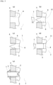
- FIGS. 4 (a) and (b) are each a schematic diagram for describing the configuration of an example of a burner lance used for implementing the method of heating up the furnace bottom of the present invention.
- FIGS. 5 (a) and (b) are schematic diagrams for describing the third aspect of the method of heating up the furnace bottom of the present invention that uses the burner lances having the configurations shown in FIGS. 4 (a) and (b) , respectively.
- the same reference numerals are given to the same components as shown in FIG. 1 , and a description thereof will be omitted.
- the configuration of the burner lance used in the present invention will be described according to FIGS. 4 (a) and (b)
- the third aspect of the method of heating up the furnace bottom of the present invention will be described according to FIGS. 5 (a) and (b) .
- the burner lance 1 shown in FIGS. 4 (a) and (b) has a double tube structure with an inner tube 21 and an outer tube 22 through which gas passes, and also has a cap 23 that covers ends of the inner tube 21 and the outer tube 22. Then, when the cap 23 exists as shown in FIG. 4 (a) , the gas blown in from a gas inlet 24 of the inner tube 21 is discharged from a gas discharging port 25 of the outer tube 22 without leaking to the outside. On the other hand, when the cap 23 does not exist as shown in FIG. 4 (b) , the gas blown in from the gas inlet 24 of the inner tube 21 is supplied into the furnace.
- the burner lance 1 has a function of cooling the burner lance 1 by passing gas from the inner tube 21 to the outer tube 22 in a state where the cap 23 exists, and a function of heating up the furnace bottom by stopping cooling by passage of the gas from the inner tube 21 to the outer tube 22 and melting and removing the cap 23, and blowing gas for heating into the furnace from the inner tube 21 of the burner lance 1.
- the cap 23 it is preferable for the cap 23 to be made of a metal such as cast iron whose fusing point is about 1100°C to 1200°C. Additionally, it is preferable for the cap 23 to be attached to the outer tube of the burner lance 1 with welding or screw fixation. Further, it is preferable to perform melting of the cap 23 by melting the cap 23 with the heat in the furnace, or by passing oxidizing gas from the inner tube 21 to the outer tube 22 to melt the cap with the heat generated by oxidization of the metal forming the cap. As the method of removing the cap, in addition to the method of melting, for example, a method of destroying with impact force, a method of removing with a mechanical mechanism, or the like can be employed. Furthermore, a thermometer 26 is provided to the burner lance 1, and the amount of blowing of the gas for cooling or the gas for heating is adjusted while confirming the temperature on the thermometer 26.
- a thermometer 26 is provided to the burner lance 1, and the amount of blowing of the gas for cooling or the gas
- the furnace bottom may be heated by blowing in and burning flammable gas + combustion-supporting gas from the burner lance 1, or the furnace bottom may be heated by blowing in combustion-supporting gas or nitrogen gas + combustion-supporting gas from the burner lance 1, and burning the coke in the furnace or the gas stagnating in the furnace.
- FIGS. 5 (a) and (b) are each a schematic diagram for describing each step of the third aspect of the method of heating up the furnace bottom of the present invention.
- the same reference numerals are given to the same components as shown in FIG. 1 , and a description thereof will be omitted.
- the third aspect of the method of heating up the furnace bottom of the present invention will be described according to FIGS. 5 (a) and (b) .
- FIG. 5 (a) is a schematic diagram in a state where the burner lance of FIG. 4 (a) is installed in the state of FIG. 3 (d) .
- FIG. 5 (b) shows a state where the cap 23 is melted and disappears with the molten material 8, and the gas for heating is being blown in. At this time, the burner lance 1 may be advanced as the melting of the molten material 8.
- the melting of the cap 23 by melting the cap 23 with the heat in the furnace, or by passing the oxidizing gas from the inner tube 21 to the outer tube 22 to melt the cap with the heat generated by oxidization of the cap 23.
- the gas for cooling may pass from the outer tube 22 to the inner tube 21.
- the gas for heating is blown into the furnace, although it is blown in from the inner tube 21, needless to say, it can be blown in from the outer tube 22.
- the furnace bottom may be heated by blowing in and burning flammable gas + combustion-supporting from burner lance 1, or the furnace bottom may be heated by blowing in combustion-supporting gas or nitrogen gas + combustion-supporting gas from the burner lance 1, and burning the coke in the furnace or the gas stagnating in the furnace.
- the tip of the burner lance After installing the burner lance in the tap hole, the tip of the burner lance is exposed to a high temperature of 1200 to 1500°C until blowing in is started.
- the tip of the burner lance When the tip of the burner lance is exposed to a high temperature for a long time, the tip of the burner lance will be eroded, and blowing-in of gas will not be able to be performed.
- molten material remains in the furnace, molten material flows backwards inside the installed burner lance, and gas blowing in becomes impossible.
- condition in the example is one exemplary condition employed in order to confirm the feasibility and effects of the present invention, and the present invention is not limited to this one exemplary condition.
- the present invention can employ various conditions as long as they can achieve the object of the present invention without departing from the gist of the present invention.
- the burner lance was installed in the tap hole, and the refractory for tap hole repairing was applied in a stamping manner in the gap between a tap hole inner wall and a burner lance outer surface. After drying for 15 minutes, the thermometer installed in the burner lance was stable about 450°C even after 3h combustion under the conditions of O 2 : 1100NM 3 /h and LNG: 300NM 3 /h, and the wear and tear of the burner lance during combustion was not confirmed.
- the opening was performed again in a situation where the tap hole was cooled, and the molten material was hardened in the tap hole.
- the opening was performed up to the tap hole depth - 50 mm, so that the tap hole does not penetrate into the furnace, and the burner lance with no cap attached to the tip was installed.
- Example 2 when it takes time to melt the solidified material at the burner lance tip portion, the time during which the burner lance is exposed to a high temperature may become long, and the burner lance tip may be deformed to cause a trouble in blowing in of gas. Additionally, there was a case where the life of the burner lance became short due to deformation of the burner lance, and blowing in could be performed only once. Therefore, heating up of the furnace bottom with the method described as the third aspect of the present invention was examined.
- the opening was performed again in a situation where the tap hole was cooled, and the molten material was hardened in the tap hole.
- the opening was performed up to the tap hole depth - 50 mm, and the burner lance having the structure shown in FIG. 4 (a) with a cap made of cast iron at the tip was installed.
- the burner lance was cooled by supplying compressed air through the inner tube to the outer tube of the burner lance having the double tube structure.
- the burner lance was pushed into the back of the tap hole with the use of a weak blow by opening machine.
- Blowing-in of LNG from the outer tube was immediately started, and it was confirmed that combustion could be continued under the conditions of O 2 : 1100NM 3 /h and LNG: 300NM 3 /h. According to this method, stable combustion became possible regardless of the state of the tap hole, and since there was no deformation of the burner lance, it was possible to perform the blowing-in multiple times.
- the burner lance used for the method when heating is performed with the burner lance provided in the tap hole at the time of startup from the blast furnace stoppage or the like, it is possible to eliminate damage to the burner lance, and to recover the furnace heat and the operation rate at early stage, thereby providing a method of heating up the furnace bottom even for various vertical-type melting furnaces other than the blast furnace.
Landscapes
- Engineering & Computer Science (AREA)
- Chemical & Material Sciences (AREA)
- Materials Engineering (AREA)
- Manufacturing & Machinery (AREA)
- Metallurgy (AREA)
- Organic Chemistry (AREA)
- General Engineering & Computer Science (AREA)
- Mechanical Engineering (AREA)
- Combustion & Propulsion (AREA)
- Blast Furnaces (AREA)
- Furnace Housings, Linings, Walls, And Ceilings (AREA)
- Furnace Details (AREA)
- Vertical, Hearth, Or Arc Furnaces (AREA)
Abstract
Description
- The present invention relates to a method of heating up a furnace bottom used for heating up a content on the furnace bottom of a blast furnace and thereafter starting blast, and to a burner lance used in the method.
- A blast furnace is a facility that heats up, reduces, and melts iron ore with high temperature reduction gas generated by the reaction between high temperature air and oxygen blown from a tuyere zone and coke and pulverized coal, and produces pig iron and slag from a tap hole provided in a lower part of a tuyere. In a normal operation of the blast furnace, where the reaction heat in the furnace and the heat supply from the tuyere are balanced, a stable operation of the blast furnace is possible. However, there are cases where it is necessary to stop blast into the blast furnace, due to operation trouble and facility trouble of the blast furnace, and production adjustment. Additionally, there are also cases where it is necessary to let the blast furnace stop for a long time for repair work due to aging of the blast furnace. During the blast stoppage, the temperature of a charged material and a molten material in the furnace (hereinafter referred to as the furnace heat) falls, due to heat removal from a furnace body / a furnace bottom, suction of air from the tuyere, and the like.
- When the furnace heat falls, the viscosity of slag is increased, and it becomes difficult to discharge molten pig iron slag from the tap hole provided below the tuyere level. When blast is started in such a state, the surface level of the molten pig iron slag (molten pig iron, molten slag, or a mixture of these) in the lower part of the furnace is increased by the molten pig iron and the slag generated by high temperature gas generated in front of the tuyere. There is no problem when the molten pig iron slag stagnating in the furnace bottom is heated up by the molten pig iron slag supplied from an upper part of the tuyere, and is gradually recovered to an appropriate furnace heat level. However, when the furnace heat is not recovered, the surface level of the molten pig iron slag reaches the tuyere level, and the tuyere is blocked, heat supplying means into the furnace is cut off, leading to a furnace-cooling accident, resulting in significant economic loss.
- In the event of a furnace-cooling accident, even when gas is blown from the tuyere zone, which is heat supplying means to the blast furnace, a problem occurs in which the tuyere zone is blocked again with the generated molten material. As a recovery method from a furnace-cooling accident, the following method has been conventionally taken. That is, first, the tuyeres other than one or two tuyeres on the tap hole are blocked with a refractory or the like during blast stoppage, and oxygen is blown from the tap hole and the tuyeres that are not blocked. Accordingly, after discharging a half-molten material between the tap hole and the tuyeres from the tap hole, a space made in the furnace is filled with coke and thereafter blast is started. Then, after establishing the temperature rising of the furnace bottom by high temperature gas that flows between the tap hole and the tuyeres, and a smooth discharging cycle of the molten pig iron slag generated with blast, the tuyeres of an adjacent portion are opened, and the number of opened tuyeres is gradually increased to recover the usual operation, which is the method that has been taken. However, these steps are long and requires one to two months. Additionally, since blowing of oxygen or the like is manually performed, it is work with a high safety risk.
- Since the furnace temperature is low at a startup after the blast stoppage, the blast furnace is exposed to a high risk of the furnace-cooling accident. To start up the blast furnace after the blast stoppage or the like without causing the furnace cooling accident, a conventional method involves increasing the coke ratio in the furnace before the blast stoppage and, without immediately blowing pulverized coal after the blast, raising the temperature (heat compensation) until pulverized coal blowing can be started. When this method is used, the charged coke ratio is reduced after confirming the stable discharging of the molten pig iron slag. Therefore, letting the blast furnace rest leads to increase in the use rate of coke, the price of which is more expensive compared with pulverized coal. Accordingly, there has been a problem that the manufacturing cost per 1 ton of molten pig iron becomes high. As another method, a method of starting blast into a blast furnace that can be started up in a short time from a long-time blast stoppage, by installing a burner in a tap hole provided in the furnace bottom of the blast furnace to burn fuel, and efficiently heating up the furnace bottom, and a burner for furnace bottom temperature rising have been proposed (Patent Literature 1).
- Patent Literature 1:
Japanese Patent Laid-Open No. 2016-30833 - However, when the burner is installed in a hole opened in the tap hole as in the above-described
Patent Literature 1, there has been a problem in which a molten material cannot be completely discharged at the time of starting blast stoppage, the molten material in the furnace flows backwards to the hole opened for installing the burner, and the burner cannot be installed. Additionally, even if the burner can be installed, there has also been a problem in which the molten material flows backward into the burner before the blowing, a pipe of the burner is blocked, and the blowing cannot be performed. - Further, when the burner is inserted into the tap hole while blowing in oxygen, in consideration that a burner tip portion may be blocked, there has also been a problem in which a part of combustion gas reacted to coke in the furnace flows backward to a direction outside the furnace, the burner wears out, and combustion cannot be performed for a long time.
- An object of the present invention is to propose a method of heating up a furnace bottom that can, when heating is performed with a lance (hereinafter generally referred to as a burner lance) having a function of blowing in combustion-supporting gas for heating up a burner provided in a tap hole and the furnace bottom at the time of startup from blast furnace stoppage or the like, eliminate damage to the burner lance, and that can recover the furnace heat and the operation rate at early stage, and a burner lance used in the method are proposed.
- As a result of earnest research for solving the aforementioned problems faced by the prior art, and achieving the aforementioned object, the inventors have come to develop a novel method of heating up a furnace bottom described below. That is, a first aspect of the present invention is a method of heating up a furnace bottom for heating up the furnace bottom by a burner lance provided in a tap hole of the furnace bottom of a blast furnace, the method including a step of opening, in the tap hole, a burner lance insertion hole having a diameter larger than a diameter of the burner lance so as to penetrate into the furnace, a step of installing the burner lance in the opened burner lance insertion hole, a step of filling a gap between the installed burner lance and a furnace exterior side of the tap hole with a refractory, and a step of blowing in gas for heating into the furnace from the burner lance to heat up the furnace bottom.
- Additionally, a second aspect of the present invention is a method of heating up a furnace bottom for heating up the furnace bottom by a burner lance provided in a tap hole of the furnace bottom of a blast furnace, the method including a step of opening, in the tap hole, a hole larger than a diameter of the burner lance so as to penetrate into the furnace, a step of solidifying a molten material that comes out from the opened hole, a step of opening a burner lance insertion hole having a diameter larger than the diameter of the burner lance in the solidified molten material so as not to penetrate into the furnace, a step of installing the burner lance in the opened burner lance insertion hole, a step of filling a gap between the installed burner lance and a furnace exterior side of the tap hole with a refractory, a step of fusing again the solidified molten material at a burner lance tip portion, and a step of blowing in gas for heating into the furnace from the burner lance to heat up the furnace bottom.
- Note that, in a third aspect of the method of heating up the furnace bottom according to the present invention configured as in the first aspect and the second aspect, it is conceivable that the following may be more preferable solutions:
- (1) in the method of heating up the furnace bottom, the burner lance used for heating up the furnace bottom has a double tube structure including an inner tube and an outer tube through which gas passes, and has a cap for covering ends of the inner tube and the outer tube of the double tube structure, the cap having a structure in which, when the cap exists, gas blown in from the inner tube is discharged from the outer tube without leaking to outside, or the gas blown in from the outer tube is discharged from the inner tube without leaking to the outside, and when the cap does not exist, the gas blown in from the inner tube or the outer tube is discharged from an end of the inner tube or the outer tube to the outside of the burner lance, when the burner lance is installed in the burner lance insertion hole, and when the gap between the installed burner lance and the furnace exterior side of the tap hole is filled with the refractory, the burner lance is cooled by passing the gas from the inner tube or the outer tube in a state where the cap exists, and after the gap between the installed burner lance and the furnace exterior side of the tap hole is filled with the refractory, the cap is removed, and the gas for heating is blown into the furnace from the burner lance to heat up the furnace bottom,
- (2) in the method of heating up the furnace bottom, removing of the cap is performed by melting the cap with heat in the furnace, or by passing oxidizing gas from the inner tube to the outer tube to melt the cap with heat generated by oxidization of the cap. Additionally, the gas at the time of cooling of the burner lance may pass from the outer tube to the inner tube.
- Further, the present invention is a burner lance used in the preferable solution, the burner lance has a double tube structure including an inner tube and an outer tube through which gas passes, the burner lance is provided with a cap for covering ends of the inner tube and the outer tube, the cap having a structure in which, when the cap exists, gas blown in from the inner tube is discharged from the outer tube without leaking to outside, or the gas blown in from the outer tube is discharged from the inner tube without leaking to the outside, and when the cap does not exist, the gas blown in from the inner tube or the outer tube is supplied to the outside of the burner lance, and the cap has a function of cooling the burner lance by passing gas through the inner tube or the outer tube in a state where the cap exists, and a function of heating up the furnace bottom by blowing in the gas for heating into the furnace from the burner lance after the cap is removed. Additionally, the burner lance may have a structure in which the gas passes from the outer tube to the inner tube.
- Note that, in the burner lance according to the present invention, it is conceivable that the following may be more preferable solutions:
- (1) the cap is attached to the outer tube of the burner lance with welding or screw fixation,
- (2) removing of the cap is performed by melting the cap with heat in the furnace, or by passing the oxidizing gas from the inner tube or the outer tube to melt the cap with heat generated by oxidization of the cap.
- According to the method of heating up the furnace bottom of the present invention, by filling the gap between the burner lance and the furnace exterior side of the tap hole with the refractory, when heating is performed with the burner lance provided in tap hole at the time of startup from the blast furnace stoppage or the like, it is possible to install the burner lance even in various situations immediately before starting blast, without damaging the burner lance. Also, by blowing in combustion-supporting gas and flammable gas or inert gas, or combustion-supporting gas from the burner lance, the recovery of the furnace heat and the operation rate at early stage are enabled. Additionally, since the blowback gas at the time of blowing in is eliminated, safe and reliable heating of the furnace bottom is possible. Further, since the certainty of the burner lance operation is increased, an operation of decreasing the coke ratio to be charged into the furnace is enabled, and it is also possible to contribute to a reduction of the molten pig iron cost.
-
- [
FIG. 1] FIG. 1 is a schematic diagram for describing an example of a refractory formed in the gap between a burner lance outer surface and a furnace exterior side inner wall of a tap hole in a method of heating up a furnace bottom of the present invention. - [
FIG. 2] FIGS. 2 (a) to (d) are each a schematic diagram for describing each step of a first aspect of the method of heating up the furnace bottom of the present invention. - [
FIG. 3] FIGS. 3 (a) to (e) are each a schematic diagram for describing each step of a second aspect of the method of heating up the furnace bottom of the present invention. - [
FIG. 4] FIGS. 4 (a) and (b) are each a schematic diagram for describing the configuration of an example of a burner lance used for implementing the method of heating up the furnace bottom of the present invention. - [
FIG. 5] FIGS. 5 (a) and (b) are schematic diagrams for describing a third aspect of the method of heating up the furnace bottom of the present invention that uses the burner lance having the configurations shown inFIGS. 4 (a) and (b) , respectively. - Hereinafter, a method of heating up a furnace bottom of the present invention will be described.
-
FIG. 1 is a schematic diagram for describing an example of a refractory formed in the gap between a burner lance outer surface and a furnace exterior side inner wall of a tap hole in the method of heating up the furnace bottom of the present invention. In the present invention, the furnace bottom of a blast furnace refers to the portion below the tuyere height of the blast furnace, and the tap hole for discharging molten pig iron and slag is provided in the furnace bottom portion. In the example shown inFIG. 1 ,reference numeral 1 denotes a burner lance, andreference numeral 2 denotes a burner refractory applied to the outer surface of theburner lance 1. Additionally,reference numeral 3 denotes a tap hole provided in the furnace bottom of afurnace wall 4, andreference numeral 5 denotes a refractory formed in the gap between theburner lance 1 and aninner surface 3 a of thetap hole 3. Further,reference numeral 6 denotes a blocking material that blocks thetap hole 3, andreference numeral 7 denotes a region where a blast furnace filling including a molten material further inside the furnace than the blockingmaterial 6 exists. Note that, although it depends on the shape of the blast furnace, as an example, it is preferable to set the layer thickness of therefractory 5 formed in the gap between theinner surface 3a of thetap hole 3 and the outer surface of the burner lance 1 to be 50 mm or more in the axial direction of theburner lance 1. - In the method of heating up the furnace bottom of the present invention, by providing the refractory 5 in the gap between the
burner lance 1 and theinner surface 3a of thetap hole 3, when heating is performed with theburner lance 1 provided in thetap hole 3 at the time of startup from blast furnace stoppage or the like, it is possible to obtain the method of heating up the furnace bottom that can eliminate damage to theburner lance 1, and that can recover the furnace heat and the operation rate at early stage. - Hereinafter, a description will be given of a specific configuration of the method of heating up the furnace bottom of the present invention in the order of a first aspect of the present invention, a second aspect of the present invention, and the configuration of a burner lance used in the present invention and a third aspect of the present invention using the burner lance.
-
FIGS. 2 (a) to (d) are each a schematic diagram for describing each step of the first aspect of the method of heating up the furnace bottom of the present invention. In the example shown inFIGS. 2 (a) to (d) , the same reference numerals are given to the same components as shown inFIG. 1 , and a description thereof will be omitted. Hereinafter, a description will be given of the first aspect of the method of heating up the furnace bottom of the present invention, according toFIGS. 2 (a) to (d) . - First, in a state where the
tap hole 3 is blocked by the blockingmaterial 6 as shown inFIG. 2 (a) , a burnerlance insertion hole 11 having a diameter larger than the diameter of theburner lance 1 is opened in thetap hole 3 so as to penetrate into the furnace as shown inFIG. 2 (b) . A known tap hole machine can be used for this opening. Next, as shown inFIG. 2 (c) , theburner lance 1 is installed in the opened burnerlance insertion hole 11. At this time, theburner lance 1 may be any kind of burner lance as long as it can maintain a flame at its tip. Finally, as shown inFIG. 2 (d) , the gap between the installedburner lance 1 and the furnace exterior side of thetap hole 3 is filled with the refractory 5. - As an example of the refractory 5 for filling, a stamping material that is used for repairing of the
tap hole 3 may be used. The refractory 5 filled from the outside is heated and hardened by a burner or the like after the filling. Then, gas for heating is blown into the furnace from theburner lance 1 to heat up the furnace bottom. As methods of blowing in gas for heating, the furnace bottom may be heated by blowing in and burning flammable gas + combustion-supporting gas fromburner lance 1, or the furnace bottom may be heated by blowing in combustion-supporting gas or nitrogen gas + combustion-supporting gas from theburner lance 1, and burning coke in the furnace. - Although it is little by little, the tip of the
burner lance 1 is eroded as the time of usage is increased. Accordingly, it is preferable for the tip position of theburner lance 1 to be installed at a position closer to the furnace center than an inside-furnace boundary surface (hereinafter referred to as an opening depth) of the refractory 5 formed by the blockingmaterial 6 of thetap hole 3. When opened to the opening depth, in a case where outflow of the molten material or the like is not confirmed, and the tip position of theburner lance 1 can be installed further inside the furnace than the opening depth, a long-time blowing-in is possible merely by implementing application of the refractory 5. -
FIGS. 3 (a) to (e) are each a schematic diagram for describing each step of the second aspect of the method of heating up the furnace bottom of the present invention. In the example shown inFIGS. 3 (a) to (e) , the same reference numerals are given to the same components as shown inFIG. 1 , and a description thereof will be omitted. Hereinafter, a description will be given of the second aspect of the method of heating up the furnace bottom of the present invention, according toFIGS. 3 (a) to (e) . - First, in a state where the
tap hole 3 is blocked by the blockingmaterial 6 as shown inFIG. 3 (a) , ahole 12 having a diameter larger than the diameter of theburner lance 1 is opened in thetap hole 3 so as to penetrate into the furnace as shown inFIG. 3 (b) . Thehole 12 can be opened by opening machine. At this time, as shown inFIG. 3 (b) , when thehole 12 reaches theregion 7 where the blast furnace filling exists, amolten material 8 may flow out of the furnace via thehole 12. In that case, as shown inFIG. 3 (c) , themolten material 8 that has come out from the openedhole 12 is solidified to be used as the blockingmaterial 6. It is preferable to perform a method of solidifying themolten material 8 by cooling the back of the hole by blowing in water, air, or both. Next, as shown inFIG. 3 (d) , the burnerlance insertion hole 11 having the diameter larger than the diameter of theburner lance 1 is opened in the solidifiedmolten material 8 so as not to penetrate into the furnace. On this occasion, perforation may be simultaneously performed while cooling and solidifying the molten material with water or air. Next, as shown inFIG. 3 (e) , theburner lance 1 is installed in the opened burnerlance insertion hole 11. Finally, as shown inFIG. 3 (e) , the gap between the installedburner lance 1 and the furnace exterior side of thetap hole 3 is filled with the refractory 5. Then, after themolten material 8 at the burner lance tip portion is melted with the heat in the furnace to release the burner lance tip into the furnace, for example, fuel gas is blown in from the burner lance and is burned. - In the above-described second aspect, in a case where the molten material cannot be sufficiently discharged to the outside of the furnace at the time of starting the blast stoppage, or when the molten material is generated during the blast stoppage due to air suction from a tuyere zone or the like during the blast stoppage, and the molten material level of the furnace bottom is rising, the molten material flows backwards in the tap hole at the time of the opening. In such a case, even if the opening is performed again after the molten material that has flown backwards is solidified, the molten material similarly flows backwards in the tap hole. Accordingly, it will be in a state where installation of the burner lance cannot be performed. In such a case, the installation of the burner lance is enabled by performing the opening again more shallowly than the opening depth, and blowing in water, air, or both, thereby preventing backflow of the molten material while temporarily cooling the back of the hole. In this situation, after installing the burner lance, when cooling of the molten material is stopped or mitigated, the molten material that has once solidified begins to melt again due to heat transfer from inside the furnace. When the solidified material in the vicinity of the burner lance tip portion is melted, the inside of the furnace can be heated up by igniting flammable gas that is discharged from the burner lance, or by discharging combustion-supporting gas. Alternatively, the inside of the furnace can be similarly heated up in a state where the solidified molten material is softened before being melted again, by advancing the burner lance to break the softened molten material with the burner lance, and placing the tip of the burner lance in the furnace.
-
FIGS. 4 (a) and (b) are each a schematic diagram for describing the configuration of an example of a burner lance used for implementing the method of heating up the furnace bottom of the present invention. Additionally,FIGS. 5 (a) and (b) are schematic diagrams for describing the third aspect of the method of heating up the furnace bottom of the present invention that uses the burner lances having the configurations shown inFIGS. 4 (a) and (b) , respectively. The same reference numerals are given to the same components as shown inFIG. 1 , and a description thereof will be omitted. Hereinafter, the configuration of the burner lance used in the present invention will be described according toFIGS. 4 (a) and (b) , and thereafter, the third aspect of the method of heating up the furnace bottom of the present invention will be described according toFIGS. 5 (a) and (b) . - The
burner lance 1 shown inFIGS. 4 (a) and (b) has a double tube structure with aninner tube 21 and anouter tube 22 through which gas passes, and also has acap 23 that covers ends of theinner tube 21 and theouter tube 22. Then, when thecap 23 exists as shown inFIG. 4 (a) , the gas blown in from agas inlet 24 of theinner tube 21 is discharged from agas discharging port 25 of theouter tube 22 without leaking to the outside. On the other hand, when thecap 23 does not exist as shown inFIG. 4 (b) , the gas blown in from thegas inlet 24 of theinner tube 21 is supplied into the furnace. Therefore, theburner lance 1 has a function of cooling theburner lance 1 by passing gas from theinner tube 21 to theouter tube 22 in a state where thecap 23 exists, and a function of heating up the furnace bottom by stopping cooling by passage of the gas from theinner tube 21 to theouter tube 22 and melting and removing thecap 23, and blowing gas for heating into the furnace from theinner tube 21 of theburner lance 1. - In the present example, it is preferable for the
cap 23 to be made of a metal such as cast iron whose fusing point is about 1100°C to 1200°C. Additionally, it is preferable for thecap 23 to be attached to the outer tube of theburner lance 1 with welding or screw fixation. Further, it is preferable to perform melting of thecap 23 by melting thecap 23 with the heat in the furnace, or by passing oxidizing gas from theinner tube 21 to theouter tube 22 to melt the cap with the heat generated by oxidization of the metal forming the cap. As the method of removing the cap, in addition to the method of melting, for example, a method of destroying with impact force, a method of removing with a mechanical mechanism, or the like can be employed. Furthermore, athermometer 26 is provided to theburner lance 1, and the amount of blowing of the gas for cooling or the gas for heating is adjusted while confirming the temperature on thethermometer 26. - Note that, in the example shown in
FIGS. 4 (a) and (b) , when theburner lance 1 is cooled, although the gas for cooling passes from theinner tube 21 to theouter tube 22, needless to say, the gas for cooling may pass from theouter tube 22 to theinner tube 21. Additionally, when the gas for heating is blown into the furnace, although it is blown in from theinner tube 21, needless to say, it can be blown in from theouter tube 22. In addition, when a flow channel corresponding to the inner tube and the outer tube is provided, multiple tubes with three or more tubes can also be used. Further, as the method of blowing in the gas for heating, the furnace bottom may be heated by blowing in and burning flammable gas + combustion-supporting gas from theburner lance 1, or the furnace bottom may be heated by blowing in combustion-supporting gas or nitrogen gas + combustion-supporting gas from theburner lance 1, and burning the coke in the furnace or the gas stagnating in the furnace. -
FIGS. 5 (a) and (b) are each a schematic diagram for describing each step of the third aspect of the method of heating up the furnace bottom of the present invention. In the example shown inFIGS. 5 (a) and (b) , the same reference numerals are given to the same components as shown inFIG. 1 , and a description thereof will be omitted. Hereinafter, the third aspect of the method of heating up the furnace bottom of the present invention will be described according toFIGS. 5 (a) and (b) . - In the third aspect of the method of heating up the furnace bottom of the present invention, when each step of the above-described first aspect and second aspect is implemented, the above-described
burner lance 1 is utilized. That is, in the first aspect and the second aspect, when theburner lance 1 is installed in the burnerlance insertion hole 11, and when the gap between the installedburner lance 1 and the furnace exterior side of thetap hole 3 is filled with the refractory 5, theburner lance 1 is cooled by passing gas from theinner tube 21 to theouter tube 22 in the state where thecap 23 exists.FIG. 5 (a) is a schematic diagram in a state where the burner lance ofFIG. 4 (a) is installed in the state ofFIG. 3 (d) . Additionally, after the gap between the installedburner lance 1 and the furnace exterior side of thetap hole 3 is filled with the refractory 5, the furnace bottom is heated up by stopping the cooling by the passage of the gas from theinner tube 21 to theouter tube 22 and melting thecap 23, and by blowing in the gas for heating into the furnace from theinner tube 21 of theburner lance 1.FIG. 5 (b) shows a state where thecap 23 is melted and disappears with themolten material 8, and the gas for heating is being blown in. At this time, theburner lance 1 may be advanced as the melting of themolten material 8. - In the above-described method of heating up the furnace bottom according to the third aspect, it is preferable to perform the melting of the
cap 23 by melting thecap 23 with the heat in the furnace, or by passing the oxidizing gas from theinner tube 21 to theouter tube 22 to melt the cap with the heat generated by oxidization of thecap 23. Additionally, also in the present example, when theburner lance 1 is cooled, although the gas for cooling passes from theinner tube 21 to theouter tube 22, needless to say, the gas for cooling may pass from theouter tube 22 to theinner tube 21. Further, when the gas for heating is blown into the furnace, although it is blown in from theinner tube 21, needless to say, it can be blown in from theouter tube 22. Further, as methods of blowing in the gas for heating, the furnace bottom may be heated by blowing in and burning flammable gas + combustion-supporting fromburner lance 1, or the furnace bottom may be heated by blowing in combustion-supporting gas or nitrogen gas + combustion-supporting gas from theburner lance 1, and burning the coke in the furnace or the gas stagnating in the furnace. - After installing the burner lance in the tap hole, the tip of the burner lance is exposed to a high temperature of 1200 to 1500°C until blowing in is started. When the tip of the burner lance is exposed to a high temperature for a long time, the tip of the burner lance will be eroded, and blowing-in of gas will not be able to be performed. When molten material remains in the furnace, molten material flows backwards inside the installed burner lance, and gas blowing in becomes impossible. In a case where the furnace bottom is heated under the condition in which the burner lance without the
cap 23 is used, and the molten material flows backwards, when installation of the burner lance is performed while gas is blown in, in consideration of the blockade by the molten material, since the burner lance is eroded by the heat of the gas blown back from the tap hole, the life of the burner lance is reduced. Additionally, since it is accompanied by scattering of high temperature materials, it is also not preferable in terms of safety. It is preferable to implement the third aspect of the method of heating up the furnace bottom of the present invention as shown inFIGS. 5 (a) and (b) , by using theburner lance 1 having the structure shown inFIGS. 4 (a) and (b) under the situations as described above. - Note that, when the method of heating up the furnace bottom of the present invention is performed by the burner lance installed in the tap hole as described above, as an example, it is preferable to block with clay three tuyeres in total, i.e., a tuyere above the tap hole position, and the left and right tuyeres thereof.
- Next, although an example of the present invention will be described, the condition in the example is one exemplary condition employed in order to confirm the feasibility and effects of the present invention, and the present invention is not limited to this one exemplary condition. The present invention can employ various conditions as long as they can achieve the object of the present invention without departing from the gist of the present invention.
- At the time of startup from blast furnace stoppage, in a status where the outflow of a molten material was not confirmed after opening a tap hole, when a burner lance was installed in the tap hole, a gas of O2: 130NM3/h was passed through an inner tube of the burner lance having a double tube structure, without filling the gap between the burner lance and the furnace exterior side of the tap hole with a refractory, and a gas of LNG:55NM3/h was passed through the gap between the inner tube and an outer tube, and the burner lance was inserted in a state where the tip is being ignited, a part of flame did not enter the furnace and blew back to the outside of the furnace. Since two thermocouples at the burner lance tip of a thermometer installed in the burner lance was broken, blowing in was interrupted.
- At the time of startup from blast furnace stoppage, in the status where the outflow of the molten material was not confirmed after opening the tap hole, the burner lance was installed in the tap hole, and the refractory for tap hole repairing was applied in a stamping manner in the gap between a tap hole inner wall and a burner lance outer surface. After drying for 15 minutes, the thermometer installed in the burner lance was stable about 450°C even after 3h combustion under the conditions of O2: 1100NM3/h and LNG: 300NM3/h, and the wear and tear of the burner lance during combustion was not confirmed.
- At the time of startup from blast furnace stoppage, after opening the tap hole, since the molten material flew backwards into the tap hole, the burner lance for heating the furnace bottom could not be installed. Although the opening was performed again in a situation where the tap hole was cooled, and the molten material was hardened in the tap hole, since the molten material flew backwards again after the opening, installation of the burner lance for heating the furnace bottom had to be abandoned.
- At the time of startup from blast furnace stoppage, after opening the tap hole, since the molten material flew backwards into the tap hole, the opening was performed again in a situation where the tap hole was cooled, and the molten material was hardened in the tap hole. The opening was performed up to the tap hole depth - 50 mm, so that the tap hole does not penetrate into the furnace, and the burner lance with no cap attached to the tip was installed. After applying the refractory to the gap between the tap hole inner wall and the burner lance outer surface, when nitrogen was supplied to the burner lance, nitrogen did not flow at first and the internal pressure of the burner was increased. However, after approximately three minutes, the internal pressure fell, and it was possible to estimate that the solidified material at the tip portion of the burner lance was eroded. Thereafter, blowing in was started under the conditions of O2: 1100NM3/h and LNG: 300NM3/h, and it was possible to heat up the furnace bottom.
- However, in the method of Example 2, when it takes time to melt the solidified material at the burner lance tip portion, the time during which the burner lance is exposed to a high temperature may become long, and the burner lance tip may be deformed to cause a trouble in blowing in of gas. Additionally, there was a case where the life of the burner lance became short due to deformation of the burner lance, and blowing in could be performed only once. Therefore, heating up of the furnace bottom with the method described as the third aspect of the present invention was examined.
- At the time of startup from blast furnace stoppage, after opening the tap hole, since the molten material flew backwards into the tap hole, the opening was performed again in a situation where the tap hole was cooled, and the molten material was hardened in the tap hole. The opening was performed up to the tap hole depth - 50 mm, and the burner lance having the structure shown in
FIG. 4 (a) with a cap made of cast iron at the tip was installed. At the time of installation, the burner lance was cooled by supplying compressed air through the inner tube to the outer tube of the burner lance having the double tube structure. At the time of insertion, the burner lance was pushed into the back of the tap hole with the use of a weak blow by opening machine. When the weak blow by the opening machine was intermittently applied while continuing the cooling of the burner lance, the molten material solidified in the tap hole was melted again after approximately 15 minutes, and the burner lance tip could be inserted to the vicinity of the tap hole depth. When a coolant gas for the burner lance was stopped at the position, a pressure was applied with O2 from the inner tube in a state where the inside of the burner lance is sealed, and the pressure in the burner lance was observed, after approximately 5 minutes, the internal pressure rapidly changed, and reached a value equal to the internal pressure of the blast furnace. At this point, it was possible to determine that the cap at the burner lance tip portion was melted and disappeared. Blowing-in of LNG from the outer tube was immediately started, and it was confirmed that combustion could be continued under the conditions of O2: 1100NM3/h and LNG: 300NM3/h. According to this method, stable combustion became possible regardless of the state of the tap hole, and since there was no deformation of the burner lance, it was possible to perform the blowing-in multiple times. - According to the method of heating up the furnace bottom according to the present invention, and the burner lance used for the method, when heating is performed with the burner lance provided in the tap hole at the time of startup from the blast furnace stoppage or the like, it is possible to eliminate damage to the burner lance, and to recover the furnace heat and the operation rate at early stage, thereby providing a method of heating up the furnace bottom even for various vertical-type melting furnaces other than the blast furnace.
-
- 1
- burner lance
- 2
- burner refractory
- 3
- tap hole
- 3a
- inner surface
- 4
- furnace wall
- 5
- refractory
- 6
- blocking material
- 7
- region where blast furnace filling exists
- 8
- molten material
- 11
- burner lance insertion hole
- 12
- hole
- 21
- inner tube
- 22
- outer tube
- 23
- cap
- 24
- gas inlet
- 25
- gas discharging port
- 26
- thermometer
Claims (7)
- A method of heating up a furnace bottom for heating up the furnace bottom by a burner lance provided in a tap hole of the furnace bottom of a blast furnace, the method characterized by comprising:a step of opening, in the tap hole, a burner lance insertion hole having a diameter larger than a diameter of the burner lance so as to penetrate into the furnace;a step of installing the burner lance in the opened burner lance insertion hole;a step of filling a gap between the installed burner lance and a furnace exterior side of the tap hole with a refractory; anda step of blowing in gas for heating into the furnace from the burner lance to heat up the furnace bottom.
- A method of heating up a furnace bottom for heating up the furnace bottom by a burner lance provided in a tap hole of the furnace bottom of a blast furnace, the method characterized by comprising:a step of opening, in the tap hole, a hole larger than a diameter of the burner lance so as to penetrate into the furnace;a step of solidifying a molten material that comes out from the opened hole;a step of opening a burner lance insertion hole having a diameter larger than the diameter of the burner lance in the solidified molten material so as not to penetrate into the furnace;a step of installing the burner lance in the opened burner lance insertion hole;a step of filling a gap between the installed burner lance and a furnace exterior side of the tap hole with a refractory;a step of fusing again the solidified molten material at a burner lance tip portion; anda step of blowing in gas for heating into the furnace from the burner lance to heat up the furnace bottom.
- The method of heating up the furnace bottom according to claim 1 or claim 2, whereinthe burner lance used for heating up the furnace bottom has a double tube structure including an inner tube and an outer tube through which gas passes, and has a cap for covering ends of the inner tube and the outer tube of the double tube structure, the cap having a structure in which, when the cap exists, gas blown in from the inner tube is discharged from the outer tube without leaking to outside, or the gas blown in from the outer tube is discharged from the inner tube without leaking to the outside, and when the cap does not exist, the gas blown in from the inner tube or the outer tube is discharged from an end of the inner tube or the outer tube to the outside of the burner lance,when the burner lance is installed in the burner lance insertion hole, and when the gap between the installed burner lance and the furnace exterior side of the tap hole is filled with the refractory, the burner lance is cooled by passing the gas from the inner tube or the outer tube in a state where the cap exists, andafter the gap between the installed burner lance and the furnace exterior side of the tap hole is filled with the refractory, the cap is removed, and the gas for heating is blown into the furnace from the burner lance to heat up the furnace bottom.
- The method of heating up the furnace bottom according to claim 3, wherein removing of the cap is performed by melting the cap with heat in the furnace, or by passing oxidizing gas from the inner tube or the outer tube to melt the cap with heat generated by oxidization of the cap.
- A burner lance used in the method of heating up the furnace bottom according to claim 3 or 4, characterized in thatthe burner lance has a double tube structure including an inner tube and an outer tube through which gas passes,the burner lance is provided with a cap for covering ends of the inner tube and the outer tube, the cap having a structure in which, when the cap exists, gas blown in from the inner tube is discharged from the outer tube without leaking to outside, or the gas blown in from the outer tube is discharged from the inner tube without leaking to the outside, and when the cap does not exist, the gas blown in from the inner tube or the outer tube is supplied to the outside of the burner lance, andthe cap has a function of cooling the burner lance by passing gas through the inner tube or the outer tube in a state where the cap exists, and a function of heating up the furnace bottom by blowing in the gas for heating into the furnace from the burner lance after the cap is removed.
- The burner lance according to claim 5, wherein the cap is attached to the outer tube of the burner lance with welding or screw fixation.
- The burner lance according to claim 5 or 6, wherein removing of the cap is performed by melting the cap with heat in the furnace, or by passing oxidizing gas from the inner tube or the outer tube to melt the cap with heat generated by oxidization of the cap.
Applications Claiming Priority (2)
| Application Number | Priority Date | Filing Date | Title |
|---|---|---|---|
| JP2019059746 | 2019-03-27 | ||
| PCT/JP2020/012587 WO2020196360A1 (en) | 2019-03-27 | 2020-03-23 | Method for heating up hearth of blast furnace, and burner lance used for same |
Publications (2)
| Publication Number | Publication Date |
|---|---|
| EP3950965A1 true EP3950965A1 (en) | 2022-02-09 |
| EP3950965A4 EP3950965A4 (en) | 2022-05-04 |
Family
ID=72610928
Family Applications (1)
| Application Number | Title | Priority Date | Filing Date |
|---|---|---|---|
| EP20777620.4A Pending EP3950965A4 (en) | 2019-03-27 | 2020-03-23 | Method for heating up hearth of blast furnace, and burner lance used for same |
Country Status (7)
| Country | Link |
|---|---|
| US (1) | US20220178612A1 (en) |
| EP (1) | EP3950965A4 (en) |
| JP (1) | JP7184164B2 (en) |
| KR (1) | KR102587684B1 (en) |
| CN (1) | CN113574184B (en) |
| TW (1) | TWI732500B (en) |
| WO (1) | WO2020196360A1 (en) |
Families Citing this family (2)
| Publication number | Priority date | Publication date | Assignee | Title |
|---|---|---|---|---|
| JP7306421B2 (en) * | 2020-05-15 | 2023-07-11 | Jfeスチール株式会社 | How to start up a blast furnace |
| TWI762408B (en) * | 2021-08-19 | 2022-04-21 | 中國鋼鐵股份有限公司 | Method for burning-off deposited carbon inside coke oven |
Family Cites Families (15)
| Publication number | Priority date | Publication date | Assignee | Title |
|---|---|---|---|---|
| DE2428642A1 (en) * | 1974-06-14 | 1976-01-02 | Sydney Steel Corp | Restarting cold blast furnaces - using lance comprising coaxial tubes providing oxygen surrounded by fuel stream |
| JPH03111503A (en) * | 1989-09-26 | 1991-05-13 | Kawasaki Steel Corp | Method for opening iron tapping hole in blast furnace |
| CN2191864Y (en) * | 1994-01-26 | 1995-03-15 | 冶金工业部钢铁研究总院 | Spray gun for jetting coal powder in blast furnace |
| JPH09241710A (en) * | 1996-03-06 | 1997-09-16 | Kawasaki Steel Corp | Method for desulfurizing molten iron in furnace hearth molten iron pool part in blast furnace |
| JP4308288B2 (en) * | 2007-09-10 | 2009-08-05 | 新日本製鐵株式会社 | Outlet structure of melting furnace and repair method |
| JP5200618B2 (en) * | 2008-03-27 | 2013-06-05 | Jfeスチール株式会社 | Blast furnace operation method |
| JP2010215940A (en) * | 2009-03-13 | 2010-09-30 | Jfe Steel Corp | Method for repairing refractory of molten iron tapping hole in blast furnace |
| CN201825967U (en) * | 2010-09-26 | 2011-05-11 | 宝山钢铁股份有限公司 | Cyclone injection lance for blast furnace injection |
| CN101984087B (en) * | 2010-11-18 | 2012-07-04 | 马鞍山钢铁股份有限公司 | Slag liquefaction heating process and device |
| US10138151B2 (en) * | 2013-05-22 | 2018-11-27 | Johns Manville | Submerged combustion burners and melters, and methods of use |
| JP5904344B2 (en) * | 2014-07-25 | 2016-04-13 | Jfeスチール株式会社 | Blast furnace blast start method and hearth temperature raising burner |
| JP6544175B2 (en) * | 2015-09-24 | 2019-07-17 | 日本製鉄株式会社 | Method of raising the temperature of the charge and residue in the bottom of the blast furnace |
| JP6358440B2 (en) * | 2015-11-05 | 2018-07-18 | Jfeスチール株式会社 | Lance pipe for blowing oxygen gas |
| RU2649160C1 (en) * | 2015-12-25 | 2018-03-30 | Тритек Ко., Лтд. | Fuel feed device |
| CN208346209U (en) * | 2018-05-29 | 2019-01-08 | 广东韶钢松山股份有限公司 | A kind of novel blast-furnace iron mouth burning oxygen rifle |
-
2020
- 2020-03-23 JP JP2021509363A patent/JP7184164B2/en active Active
- 2020-03-23 EP EP20777620.4A patent/EP3950965A4/en active Pending
- 2020-03-23 WO PCT/JP2020/012587 patent/WO2020196360A1/en unknown
- 2020-03-23 KR KR1020217028472A patent/KR102587684B1/en active IP Right Grant
- 2020-03-23 US US17/441,770 patent/US20220178612A1/en active Pending
- 2020-03-23 CN CN202080021099.7A patent/CN113574184B/en active Active
- 2020-03-26 TW TW109110118A patent/TWI732500B/en active
Also Published As
| Publication number | Publication date |
|---|---|
| CN113574184A (en) | 2021-10-29 |
| US20220178612A1 (en) | 2022-06-09 |
| KR102587684B1 (en) | 2023-10-10 |
| JPWO2020196360A1 (en) | 2020-10-01 |
| CN113574184B (en) | 2022-11-29 |
| WO2020196360A1 (en) | 2020-10-01 |
| TW202035705A (en) | 2020-10-01 |
| EP3950965A4 (en) | 2022-05-04 |
| JP7184164B2 (en) | 2022-12-06 |
| TWI732500B (en) | 2021-07-01 |
| BR112021018826A2 (en) | 2021-11-23 |
| KR20210123387A (en) | 2021-10-13 |
Similar Documents
| Publication | Publication Date | Title |
|---|---|---|
| EP3950965A1 (en) | Method for heating up hearth of blast furnace, and burner lance used for same | |
| JP6544175B2 (en) | Method of raising the temperature of the charge and residue in the bottom of the blast furnace | |
| US11821048B2 (en) | Hole-opening bit and tap hole opening method using same | |
| US10781497B2 (en) | Method of sealing and repairing a refractory tap hole | |
| US20160153715A1 (en) | A solids injection lance | |
| RU2784402C1 (en) | Method for heating of blast furnace bottom and burner tuyere used in method | |
| JP7306421B2 (en) | How to start up a blast furnace | |
| JP4747662B2 (en) | Lance for blowing gas reducing material, blast furnace and blast furnace operating method | |
| BR112021018826B1 (en) | METHOD OF HEATING AN OVEN BOTTOM AND BURNER LANCE USED IN THE METHOD | |
| US20120175827A1 (en) | Method and system of removing accretion buildup in a furnace | |
| TWI779501B (en) | Guiding device, guiding system and operation method thereof | |
| KR101032503B1 (en) | Method for Last Blow Working of Blast Furnace | |
| WO2024122239A1 (en) | Blast-furnace operating method | |
| RU226787U1 (en) | CHISEL FOR OPENING OUTLET HOLE | |
| KR101090873B1 (en) | Apparatus for closing tap hole of the blast furnace | |
| JPH0649518A (en) | Closing method for blast furnace tuyere | |
| KR20030052185A (en) | Apparatus for closing tapping hole of molten steel furnace | |
| JP2024013311A (en) | Blast furnace operation method | |
| JP2001064706A (en) | Operation of blast furnace |
Legal Events
| Date | Code | Title | Description |
|---|---|---|---|
| STAA | Information on the status of an ep patent application or granted ep patent |
Free format text: STATUS: THE INTERNATIONAL PUBLICATION HAS BEEN MADE |
|
| PUAI | Public reference made under article 153(3) epc to a published international application that has entered the european phase |
Free format text: ORIGINAL CODE: 0009012 |
|
| STAA | Information on the status of an ep patent application or granted ep patent |
Free format text: STATUS: REQUEST FOR EXAMINATION WAS MADE |
|
| 17P | Request for examination filed |
Effective date: 20211019 |
|
| AK | Designated contracting states |
Kind code of ref document: A1 Designated state(s): AL AT BE BG CH CY CZ DE DK EE ES FI FR GB GR HR HU IE IS IT LI LT LU LV MC MK MT NL NO PL PT RO RS SE SI SK SM TR |
|
| A4 | Supplementary search report drawn up and despatched |
Effective date: 20220405 |
|
| RIC1 | Information provided on ipc code assigned before grant |
Ipc: C21B 7/24 20060101ALI20220330BHEP Ipc: C21B 7/16 20060101ALI20220330BHEP Ipc: F27D 99/00 20100101ALI20220330BHEP Ipc: F27B 1/10 20060101ALI20220330BHEP Ipc: C21B 7/00 20060101ALI20220330BHEP Ipc: C21B 5/00 20060101AFI20220330BHEP |
|
| DAV | Request for validation of the european patent (deleted) | ||
| DAX | Request for extension of the european patent (deleted) |