EP3950658A1 - Esterification apparatus and esterification method - Google Patents
Esterification apparatus and esterification method Download PDFInfo
- Publication number
- EP3950658A1 EP3950658A1 EP20869014.9A EP20869014A EP3950658A1 EP 3950658 A1 EP3950658 A1 EP 3950658A1 EP 20869014 A EP20869014 A EP 20869014A EP 3950658 A1 EP3950658 A1 EP 3950658A1
- Authority
- EP
- European Patent Office
- Prior art keywords
- heat source
- liquid
- esterification reaction
- partition regions
- source supply
- Prior art date
- Legal status (The legal status is an assumption and is not a legal conclusion. Google has not performed a legal analysis and makes no representation as to the accuracy of the status listed.)
- Granted
Links
Images



Classifications
-
- B—PERFORMING OPERATIONS; TRANSPORTING
- B01—PHYSICAL OR CHEMICAL PROCESSES OR APPARATUS IN GENERAL
- B01J—CHEMICAL OR PHYSICAL PROCESSES, e.g. CATALYSIS OR COLLOID CHEMISTRY; THEIR RELEVANT APPARATUS
- B01J19/00—Chemical, physical or physico-chemical processes in general; Their relevant apparatus
- B01J19/0006—Controlling or regulating processes
- B01J19/0013—Controlling the temperature of the process
-
- B—PERFORMING OPERATIONS; TRANSPORTING
- B01—PHYSICAL OR CHEMICAL PROCESSES OR APPARATUS IN GENERAL
- B01J—CHEMICAL OR PHYSICAL PROCESSES, e.g. CATALYSIS OR COLLOID CHEMISTRY; THEIR RELEVANT APPARATUS
- B01J19/00—Chemical, physical or physico-chemical processes in general; Their relevant apparatus
- B01J19/0046—Sequential or parallel reactions, e.g. for the synthesis of polypeptides or polynucleotides; Apparatus and devices for combinatorial chemistry or for making molecular arrays
-
- B—PERFORMING OPERATIONS; TRANSPORTING
- B01—PHYSICAL OR CHEMICAL PROCESSES OR APPARATUS IN GENERAL
- B01J—CHEMICAL OR PHYSICAL PROCESSES, e.g. CATALYSIS OR COLLOID CHEMISTRY; THEIR RELEVANT APPARATUS
- B01J19/00—Chemical, physical or physico-chemical processes in general; Their relevant apparatus
- B01J19/0053—Details of the reactor
-
- B—PERFORMING OPERATIONS; TRANSPORTING
- B01—PHYSICAL OR CHEMICAL PROCESSES OR APPARATUS IN GENERAL
- B01J—CHEMICAL OR PHYSICAL PROCESSES, e.g. CATALYSIS OR COLLOID CHEMISTRY; THEIR RELEVANT APPARATUS
- B01J19/00—Chemical, physical or physico-chemical processes in general; Their relevant apparatus
- B01J19/18—Stationary reactors having moving elements inside
-
- C—CHEMISTRY; METALLURGY
- C07—ORGANIC CHEMISTRY
- C07C—ACYCLIC OR CARBOCYCLIC COMPOUNDS
- C07C67/00—Preparation of carboxylic acid esters
- C07C67/08—Preparation of carboxylic acid esters by reacting carboxylic acids or symmetrical anhydrides with the hydroxy or O-metal group of organic compounds
-
- B—PERFORMING OPERATIONS; TRANSPORTING
- B01—PHYSICAL OR CHEMICAL PROCESSES OR APPARATUS IN GENERAL
- B01J—CHEMICAL OR PHYSICAL PROCESSES, e.g. CATALYSIS OR COLLOID CHEMISTRY; THEIR RELEVANT APPARATUS
- B01J2219/00—Chemical, physical or physico-chemical processes in general; Their relevant apparatus
- B01J2219/00049—Controlling or regulating processes
- B01J2219/00051—Controlling the temperature
- B01J2219/00074—Controlling the temperature by indirect heating or cooling employing heat exchange fluids
-
- B—PERFORMING OPERATIONS; TRANSPORTING
- B01—PHYSICAL OR CHEMICAL PROCESSES OR APPARATUS IN GENERAL
- B01J—CHEMICAL OR PHYSICAL PROCESSES, e.g. CATALYSIS OR COLLOID CHEMISTRY; THEIR RELEVANT APPARATUS
- B01J2219/00—Chemical, physical or physico-chemical processes in general; Their relevant apparatus
- B01J2219/00049—Controlling or regulating processes
- B01J2219/00051—Controlling the temperature
- B01J2219/00074—Controlling the temperature by indirect heating or cooling employing heat exchange fluids
- B01J2219/00076—Controlling the temperature by indirect heating or cooling employing heat exchange fluids with heat exchange elements inside the reactor
- B01J2219/00081—Tubes
-
- B—PERFORMING OPERATIONS; TRANSPORTING
- B01—PHYSICAL OR CHEMICAL PROCESSES OR APPARATUS IN GENERAL
- B01J—CHEMICAL OR PHYSICAL PROCESSES, e.g. CATALYSIS OR COLLOID CHEMISTRY; THEIR RELEVANT APPARATUS
- B01J2219/00—Chemical, physical or physico-chemical processes in general; Their relevant apparatus
- B01J2219/00049—Controlling or regulating processes
- B01J2219/00051—Controlling the temperature
- B01J2219/00074—Controlling the temperature by indirect heating or cooling employing heat exchange fluids
- B01J2219/00076—Controlling the temperature by indirect heating or cooling employing heat exchange fluids with heat exchange elements inside the reactor
- B01J2219/00083—Coils
-
- B—PERFORMING OPERATIONS; TRANSPORTING
- B01—PHYSICAL OR CHEMICAL PROCESSES OR APPARATUS IN GENERAL
- B01J—CHEMICAL OR PHYSICAL PROCESSES, e.g. CATALYSIS OR COLLOID CHEMISTRY; THEIR RELEVANT APPARATUS
- B01J2219/00—Chemical, physical or physico-chemical processes in general; Their relevant apparatus
- B01J2219/00049—Controlling or regulating processes
- B01J2219/00051—Controlling the temperature
- B01J2219/00159—Controlling the temperature controlling multiple zones along the direction of flow, e.g. pre-heating and after-cooling
-
- B—PERFORMING OPERATIONS; TRANSPORTING
- B01—PHYSICAL OR CHEMICAL PROCESSES OR APPARATUS IN GENERAL
- B01J—CHEMICAL OR PHYSICAL PROCESSES, e.g. CATALYSIS OR COLLOID CHEMISTRY; THEIR RELEVANT APPARATUS
- B01J2219/00—Chemical, physical or physico-chemical processes in general; Their relevant apparatus
- B01J2219/00049—Controlling or regulating processes
- B01J2219/00182—Controlling or regulating processes controlling the level of reactants in the reactor vessel
-
- B—PERFORMING OPERATIONS; TRANSPORTING
- B01—PHYSICAL OR CHEMICAL PROCESSES OR APPARATUS IN GENERAL
- B01J—CHEMICAL OR PHYSICAL PROCESSES, e.g. CATALYSIS OR COLLOID CHEMISTRY; THEIR RELEVANT APPARATUS
- B01J2219/00—Chemical, physical or physico-chemical processes in general; Their relevant apparatus
- B01J2219/00049—Controlling or regulating processes
- B01J2219/00191—Control algorithm
- B01J2219/00193—Sensing a parameter
- B01J2219/00195—Sensing a parameter of the reaction system
-
- B—PERFORMING OPERATIONS; TRANSPORTING
- B01—PHYSICAL OR CHEMICAL PROCESSES OR APPARATUS IN GENERAL
- B01J—CHEMICAL OR PHYSICAL PROCESSES, e.g. CATALYSIS OR COLLOID CHEMISTRY; THEIR RELEVANT APPARATUS
- B01J2219/00—Chemical, physical or physico-chemical processes in general; Their relevant apparatus
- B01J2219/00049—Controlling or regulating processes
- B01J2219/00191—Control algorithm
- B01J2219/00222—Control algorithm taking actions
-
- B—PERFORMING OPERATIONS; TRANSPORTING
- B01—PHYSICAL OR CHEMICAL PROCESSES OR APPARATUS IN GENERAL
- B01J—CHEMICAL OR PHYSICAL PROCESSES, e.g. CATALYSIS OR COLLOID CHEMISTRY; THEIR RELEVANT APPARATUS
- B01J2219/00—Chemical, physical or physico-chemical processes in general; Their relevant apparatus
- B01J2219/00274—Sequential or parallel reactions; Apparatus and devices for combinatorial chemistry or for making arrays; Chemical library technology
- B01J2219/00277—Apparatus
- B01J2219/00279—Features relating to reactor vessels
- B01J2219/00306—Reactor vessels in a multiple arrangement
-
- B—PERFORMING OPERATIONS; TRANSPORTING
- B01—PHYSICAL OR CHEMICAL PROCESSES OR APPARATUS IN GENERAL
- B01J—CHEMICAL OR PHYSICAL PROCESSES, e.g. CATALYSIS OR COLLOID CHEMISTRY; THEIR RELEVANT APPARATUS
- B01J2219/00—Chemical, physical or physico-chemical processes in general; Their relevant apparatus
- B01J2219/00274—Sequential or parallel reactions; Apparatus and devices for combinatorial chemistry or for making arrays; Chemical library technology
- B01J2219/00277—Apparatus
- B01J2219/00495—Means for heating or cooling the reaction vessels
-
- C—CHEMISTRY; METALLURGY
- C07—ORGANIC CHEMISTRY
- C07C—ACYCLIC OR CARBOCYCLIC COMPOUNDS
- C07C2601/00—Systems containing only non-condensed rings
- C07C2601/12—Systems containing only non-condensed rings with a six-membered ring
- C07C2601/14—The ring being saturated
Definitions
- One aspect of the present invention is to provide an esterification reaction apparatus and esterification reaction method, which are capable of increasing in heat transfer efficiency and preventing a raw material from being carbonized when a heat source is supplied to an accommodation part of a reaction tank so that the heat source is supplied to the raw material to cause an esterification reaction.
- the heating unit 120 may individually heat each of the partition regions N, N-1, and N-2, which are divided into N (N is an integer of 2 or more) regions in a vertical direction of the accommodation part 111. (Although three partition regions are shown in FIG. 3 , the number of partition regions in the accommodation part of the present invention is not necessarily limited to three.)
- the carboxylic acid and the alcohol which are heated through the heating unit 120, may cause an esterification reaction to generate an ester-based material and water as products of the esterification reaction.
- the liquid ester-based material may be generated by the esterification reaction and then be discharged to the outside of the reaction tank 110 through a liquid material discharge part 160, and the water may be generated, but be vaporized to be discharged to the outside of the reaction tank 110 through a vaporized material discharge part 170.
- the liquid-accommodated state in the N partition regions N, N-1, and N-2 may be individually sensed through a sensing unit 140.
- the liquid-accommodated state information sensed through the sensing unit 140 may be transmitted to the controller 130.
Landscapes
- Chemical & Material Sciences (AREA)
- Organic Chemistry (AREA)
- Chemical Kinetics & Catalysis (AREA)
- Physical Or Chemical Processes And Apparatus (AREA)
- Organic Low-Molecular-Weight Compounds And Preparation Thereof (AREA)
Abstract
Description
- The present application claims the benefit of the priority of
Korean Patent Application No. 10-2019-0119165, filed on September 26, 2019 - The present invention relates to an esterification reaction apparatus and an esterification reaction method.
- A phthalate-based plasticizer accounts for 92% of the global plasticizer market until the 20th century (see Mustafizur Rahman and Christopher S.Brazel "The plasticizer market: an assessment of traditional plasticizers and research trends to meet new challenges" Progress in Polymer Science 2004, 29, 1223-1248). The phthalate-based plasticizer is an additive used for imparting flexibility, durability and cold resistance mainly to polyvinyl chloride (hereinafter, referred to as PVC) and lowering the viscosity during melting to improve processability. The phthalate-based plasticizer is added in various amounts to PVC and widely used in various applications from rigid products such as rigid pipes to soft products which may be used for such as food packaging materials, blood bags, flooring materials, etc. due to its soft and good flexibility. Therefore, it is more closely related to real life than any other material, and the direct contact with the human body may not avoidable.
- However, in spite of the compatibility of the phthalate-based plasticizer with PVC and its excellent capability to impart flexibility, it has been argued recently about harmfulness of the PVC product containing the phthalate-based plasticizer that the phthalate-based plasticizer may leak out of the PVC product when used in real life, and act as a presumed endocrine disrupting (environmental hormone) substance and a carcinogen of the level of heavy metals (see N. R. Janjua et al. "Systemic Uptake of Diethyl Phthalate, Dibutyl Phthalate, and Butyl Paraben Following Whole-body Topical Application and Reproductive and Thyroid Hormone Levels in Humans" Environmental Science and Technology 2008, 42, 7522-7527). Particularly, since the report about the leakage of di-(2-ethyl hexyl) phthalate (DEHP), which has been the most used phthalate-based plasticizer in the U.S in the 1960s, out of the PVC product, the interest in environmental hormones have been added in the 1990s and global environmental regulations as well as various studies on hazards of the phthalate-based plasticizer to human have been started.
- As a result, many researchers are conducting research to develop spill control technologies that suppress leakage of the phthalate plasticizer to not only significantly reduce the human risk but also meet environmental standards, as well as, develop a new non-phthalate-based alternative plasticizer that exclude phthalic anhydride used in the manufacture of di(2-ethylhexyl) phthalate or develop a phthalate plasticizer that is capable of replacing di(2-ethylhexyl) phthalate, which are used for industrial purposes due to the suppression of leakage of the plasticizer although being based on phthalate, in order to respond to environmental hormone problems and environmental regulations caused by the leakage of the phthalate plasticizer, particularly, di(2-ethylhexyl) phthalate.
- As described above, development of materials that are free from environmental problems capable of replacing di(2-ethylhexyl) phthalate, which has existing environmental problems, as a diester-based plasticizer is actively progressing, and research on developing diester plasticizers with excellent physical properties, as well as research on facilities for manufacturing such plasticizers, is actively being conducted. Here, in terms of process design, more efficient, economical, and simple process design is required.
- In order to manufacture the above diester plasticizer, the diester plasticizer is manufactured including a reaction process in which heat is applied to a raw material to perform an esterification reaction, but when a heat source is supplied to the raw material in the reaction process, the heat transfer efficiency is low, and the raw material is carbonized to generate foreign substances.
- [Prior Art Document] (Patent Document)
Korean Patent Publication No. 10-2019-0027623 - One aspect of the present invention is to provide an esterification reaction apparatus and esterification reaction method, which are capable of increasing in heat transfer efficiency and preventing a raw material from being carbonized when a heat source is supplied to an accommodation part of a reaction tank so that the heat source is supplied to the raw material to cause an esterification reaction.
- An esterification reaction apparatus comprises: a reaction tank having an accommodation part, in which a raw material containing carboxylic acid and alcohol to be supplied is accommodated, therein; a heating unit configured to individually heat partition regions that are partitioned into N (N is an integer of 2 or more) regions in a vertical direction of the accommodation part; and a controller configured to control the heating unit so that only the partition regions, in which a liquid is accommodated, among the N partition regions are heated by controlling the heating unit, thereby performing an esterification reaction of the raw material.
- An esterification reaction method comprises: a supply process of supplying a raw material containing carboxylic acid and alcohol to an accommodation part of a reaction tank; a heating process of individually heating partition regions that are partitioned into N (N is an integer of 2 or more) regions in a vertical direction of the accommodation part through a heating unit; and a control process of controlling the heating unit through a controller during the heating process so that only the partition regions, in which a liquid is accommodated, among the N partition regions are heated, thereby performing an esterification reaction of the raw material.
- According to the present invention, the heat transfer efficiency may increase by supplying the heat source to only the wet region, in which the liquid is accommodated, in the accommodation part of the reaction tank in which the esterification reaction occurs by applying the heat to the raw material containing carboxylic acid and alcohol. Here, the supply of the heat source to the dry region in which the liquid is not accommodated in the accommodation part may be blocked to prevent the foreign substances from being generated due to the carbonization of the raw material disposed in the dry region.
-
-
FIG. 1 is a perspective view of an esterification reaction apparatus according to an embodiment of the present invention. -
FIG. 2 is a cross-sectional view of the esterification reaction apparatus according to an embodiment of the present invention. -
FIG. 3 is a conceptual cross-sectional view illustrating an example of the esterification reaction apparatus according to an embodiment of the present invention. -
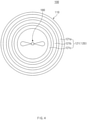
FIG. 4 is a plan view illustrating an example of the inside of a reaction tank in the esterification reaction apparatus according to an embodiment of the present invention. -
FIG. 5 is an exploded perspective view illustrating an example of a plurality of heat source supply tube, which is provided in a heat source supply part, in the esterification reaction apparatus according to an embodiment of the present invention. - The objectives, specific advantages, and novel features of the present invention will become more apparent from the following detailed description taken in conjunction with the accompanying drawings. It should be noted that the reference numerals are added to the components of the drawings in the present specification with the same numerals as possible, even if they are illustrated in other drawings. Also, the present invention may be embodied in different forms and should not be construed as limited to the embodiments set forth herein. In the following description of the present invention, the detailed descriptions of related arts which may unnecessarily obscure the gist of the present invention will be omitted.
-
FIG. 1 is a perspective view of an esterification reaction apparatus according to an embodiment of the present invention,FIG. 2 is a cross-sectional view of the esterification reaction apparatus according to an embodiment of the present invention, andFIG. 3 is a conceptual cross-sectional view illustrating an example of the esterification reaction apparatus according to an embodiment of the present invention. -
FIG. 4 is a plan view illustrating an example of the inside of a reaction tank in the esterification reaction apparatus according to an embodiment of the present invention, andFIG. 5 is an exploded perspective view illustrating an example of a plurality of heat source supply tube, which is provided in a heat source supply part, in the esterification reaction apparatus according to an embodiment of the present invention. - Referring to
FIGS. 1 to 3 , anesterification reaction apparatus 100 according to an embodiment of the present invention comprises areaction tank 110 in which anaccommodation part 111 is formed, aheating unit 120 that individually heats partition regions N, N-1, and N-2 of theaccommodation part 111, and acontroller 130 controlling theheating unit 120 to perform an esterification reaction of a raw material. Theesterification reaction apparatus 100 according to an embodiment of the present invention may further comprise a sensing unit 140 for sensing a liquid-accommodated state. - In more detail, the
reaction tank 110 comprises anaccommodation part 111 in which the raw material containing carboxylic acid and alcohol, which are supplied from the outside, is accommodated. - Here, the carboxylic acid may comprise, for example, one or more materials selected from the group consisting of terephthalic acid, phthalic acid, isophthalic acid, and cyclohexane dicarboxylic acid.
- Here, the alcohol may have 3 to 10 alkyl carbon atoms.
- The raw material may be supplied from the outside of the
reaction tank 110 to theaccommodation part 111 of thereaction tank 110 through a rawmaterial supply part 150. Here, the raw material supplied to theaccommodation part 111 of thereaction tank 110 may be stirred through astirrer 180 disposed in theaccommodation part 111 of thereaction tank 110. Here, afirst control valve 151 is provided in the rawmaterial supply part 150 to control the supply of the raw material. - The
heating unit 120 may individually heat each of the partition regions N, N-1, and N-2, which are divided into N (N is an integer of 2 or more) regions in a vertical direction of theaccommodation part 111. (Although three partition regions are shown inFIG. 3 , the number of partition regions in the accommodation part of the present invention is not necessarily limited to three.) - Also, the
heating unit 120 may comprise N heatsource supply parts heating unit 120 may further comprise a supply part valve V for opening and closing each of the N heatsource supply parts - Furthermore, the
heating unit 120 may comprise, for example, a first heatsource supply part 121 disposed in an upper portion of theaccommodation part 111 in the vertical direction, a second heatsource supply part 122 disposed at a central portion of theaccommodation part 111, and a third heatsource supply part 123 disposed in a lower portion of theaccommodation part 111, but the number of heatsource supply parts heating unit 120 is not necessarily limited thereto. Here, theheating unit 120 may comprise, for example, a first supply part valve V1 for opening and closing the first heatsource supply part 121, a second supply part valve V2 for opening and closing the second heatsource supply part 122, and a third supply part valve V3 for opening and closing the third heatsource supply part 123. - Referring to
FIGS. 2 to 5 , the heatsource supply parts source supply tubes source supply parts source supply tubes source supply parts - Also, the heat source supply
part source supply tubes source supply parts source supply tubes accommodation part 111 of thereaction tank 110. Here, the heatsource supply parts accommodation part 111, which supplies the heat source, among the N heatsource supply parts - Furthermore, the plurality of heat
source supply tubes source supply tubes source supply tubes source supply tubes source supply tubes reaction tank 110, the third heatsource supply tubes accommodation part 111, and the second heatsource supply tubes source supply tubes source supply tubes source supply tubes source supply tubes source supply tubes source supply parts - Also, the plurality of heat
source supply tubes accommodation part 111 in thereaction tank 110. - Also, a coil pitch P of each of the heat
source supply tubes accommodation part 111 may be equal to or less than a coil pitch P of each of the heatsource supply tubes accommodation part 111, in which the liquid raw material is accommodated always, may be more improved to improve the reaction efficiency. - The carboxylic acid and the alcohol, which are heated through the
heating unit 120, may cause an esterification reaction to generate an ester-based material and water as products of the esterification reaction. Here, the liquid ester-based material may be generated by the esterification reaction and then be discharged to the outside of thereaction tank 110 through a liquidmaterial discharge part 160, and the water may be generated, but be vaporized to be discharged to the outside of thereaction tank 110 through a vaporizedmaterial discharge part 170. - For example, the liquid
material discharge part 160 may be connected to a lower portion of thereaction tank 110, and the vaporizedmaterial discharge part 170 may be connected to an upper portion of thereaction tank 110. - Also, a
second control valve 161 may be provided in the liquidmaterial discharge part 160 to control the discharge of the generated liquid material, and athird control valve 171 may be provided in the vaporizedmaterial discharge part 170 to control the discharge of the vaporized material. (seeFIG. 1 ) - Referring to
FIG. 3 , the sensing unit 140 may sense a liquid-accommodated state in the N partition regions N, N-1, and N-2 of theaccommodation part 111. - In addition, the sensing unit 140 may transmit the sensed liquid-accommodated state information to the
controller 130. - Furthermore, the sensing unit 140 may comprise
liquid level sensors reaction tank 110 to measure an accommodated height (level) of a liquid R accommodated in theaccommodation part 111. - Here, the sensing unit 140 may comprise a first
liquid level sensor 141 disposed in the upper portion of theaccommodation part 111 of thereaction tank 110 and a secondliquid level sensor 142 disposed in the lower portion of theaccommodation part 111 of thereaction tank 110. - Referring to
FIGS. 1 and3 , thecontroller 130 may control theheating unit 120 to heat only the partition region N, N-1, and N-2, in which the liquid R is disposed, among the N partition regions N, N-1, and N-2. Here, thecontroller 130 may control the supply part valve V for opening and closing each of the N heatsource supply parts heating unit 120. - In addition, the
controller 130 may determine whether the liquid is accommodated in each of the partition regions N, N-1, and N-2 of theaccommodation part 111 through level-sensed values of the accommodated liquid R, which are sensed through the sensing unit 140. Here, thecontroller 130 may control the supply of the high-temperature liquid so that the high-temperature liquid is supplied to the heatsource supply tubes source supply tubes - Here, the partition regions N, N-1, and N-2, which are heated by supplying the high-temperature fluid to the heat
source supply tubes source supply tubes controller 130 so that the corresponding partition regions N, N-1, and N-2 are individually heated through the heatsource supply tubes heating unit 120. - The
controller 130 may be connected to the rawmaterial supply part 150 through thefirst control valve 151, connected to the liquidmartial discharge part 160 through thesecond control valve 161, and connected to the vaporizedmaterial discharge part 170 through thethird control valve 171 to control thefirst control valve 151, thesecond control valve 161, and thethird control valve 171. (Here, since the technology in which the valve is electrically controlled through the controller is a known technology, descriptions of the operation principle and control principle of the valve will be omitted) - Referring to
FIGS. 1 to 3 , in theesterification reaction apparatus 100, which comprises the above-described constituents, according to an embodiment of the present invention, theaccommodation part 111 of thereaction tank 110 may be partitioned into N regions in which the heat is applied to the raw material containing carboxylic acid and alcohol to cause the esterification reaction, and the partition regions N, N-1, and N-2 may be individually heated through theheating unit 120. Here, the controller may control theheating unit 120 so that only the partition regions N, N-1, and N-2, in which the liquid R is accommodated, are heated. - Accordingly, the heat source may be supplied to only the wet region, in which the liquid R is accommodated, among the N partition regions N, N-1, and N-2 of the
accommodation part 111 to significantly improve the heat transfer efficiency. That is, when the heat is applied to the raw material mixed with liquid carboxylic acid and alcohol to cause the esterification reaction, only the region in which the raw material solution, in which the carboxylic acid and the alcohol are mixed, is accommodated to cause the esterification reaction may be heated to prevent a problem in which the heat source is unnecessarily applied to the region in which the raw material solution is not accommodated so as not to cause the esterification reaction, to deteriorate the efficiency. - Also, the supply of the heat source to a dry region in which the liquid R is not accommodated may be blocked to prevent the raw material from being carbonized. That is, when the heat is applied to the raw material mixed with the liquid carboxylic acid and the alcohol to cause the esterification reaction, a problem, in which the heat is applied to a solid or gaseous material in the raw material to carbonize the solid or gaseous material, thereby generating foreign substances, may be prevented by blocking the supply of the heat source to the dry region.
- Hereinafter, an esterification reaction method according to an embodiment of the present invention will be described.
- Referring to
FIGS. 1 to 3 , an esterification reaction method according to an embodiment of the present invention comprises a supply process of supplying a raw material to anaccommodation part 111 of areaction tank 110, a heating process of heating partition regions N, N-1, and N-2 of theaccommodation part 111, and a control process of controlling aheating unit 120 through a controller during the heating process to perform an esterification reaction. In addition, the esterification reaction method according to an embodiment of the present invention may further comprise a sensing process of sensing a liquid-accommodated state. - In more detail, in the supply process, the raw material containing carboxylic acid and alcohol may be supplied to the
accommodation part 111 of thereaction tank 110. - In addition, in the supply process, for example, the liquid carboxylic acid and alcohol may be mixed and supplied to the
accommodation part 111 of thereaction tank 110 through a rawmaterial supply part 150. Here, afirst control valve 151 is provided in the rawmaterial supply part 150 to control the supply of the raw material. - The carboxylic acid may comprise, for example, one or more materials selected from the group consisting of terephthalic acid, phthalic acid, isophthalic acid, and cyclohexane dicarboxylic acid.
- The alcohol may have 3 to 10 alkyl carbon atoms.
- Also, a molar ratio of an amount of added carboxylic acid and a total amount of added alcohol to the
accommodation part 111 of thereaction tank 110 during the supply process may be, for example, 1:2 to 1:5. - In the heating process, the partition regions N, N-1, and N-2 that are divided into N (N is an integer of 2 or more) regions in a vertical direction of the
accommodation part 111 may be individually heated through theheating unit 120. - In addition, in the heating process, the partition regions N, N-1, and N-2 of the
accommodation part 111 may be individually heated through N heatsource supply parts heating unit 120, which are respectively provided in N partition regions N, N-1, and N-2. - Furthermore, the partition regions N, N-1, and N-2 of the
accommodation part 111 may be individually heated using heatsource supply tubes source supply parts - In addition, in the heating process, steam may be used as the high-temperature fluid passing through the heat
source supply tubes - The carboxylic acid and the alcohol may cause the esterification reaction through the heating process to generate an ester-based material and water as products of the esterification reaction.
- Here, the liquid ester-based material, which is generated through the esterification reaction, may be discharged to the outside of the
reaction tank 110 through a liquidmaterial discharge part 160, and the water may be vaporized to be discharged to the outside of thereaction tank 110 through a vaporizedmaterial discharge part 170. - For example, the liquid
material discharge part 160 may be connected to a lower portion of thereaction tank 110, and the vaporizedmaterial discharge part 170 may be connected to an upper portion of thereaction tank 110. - Also, a
second control valve 161 may be provided in the liquidmaterial discharge part 160 to control the discharge of the generated liquid material, and athird control valve 171 may be provided in the vaporizedmaterial discharge part 170 to control the discharge of the vaporized material such as the vaporized alcohol and water. - In the sensing process, the liquid-accommodated state in the N partition regions N, N-1, and N-2 may be individually sensed through a sensing unit 140. Here, in the sensing process, the liquid-accommodated state information sensed through the sensing unit 140 may be transmitted to the
controller 130. - In addition, in the sensing process, an accommodated level (height) of a liquid R accommodated in the
accommodation part 111 may be sensed through a liquid level sensor disposed inside thereaction tank 110, which is the sensing unit 140. - In the control process, the
heating unit 120 may be controlled through thecontroller 130 during the heating process so that only the partition regions N, N-1, and N-2, in which the liquid R is accommodated, among the N partition regions N, N-1, and N-2 are heated by theheating unit 120. - In addition, in the control process, the
controller 130 may determine whether the liquid is accommodated in each of the partition regions N, N-1, and N-2 of theaccommodation part 111 through level-sensed values of the accommodated liquid R, which are sensed in the sensing process. Here, in the control process, thecontroller 130 may control the supply of the high-temperature liquid so that the high-temperature liquid is supplied to the heatsource supply tubes source supply tubes - Furthermore, in the control process, for example, the
controller 130 may control opening and closing of a supply part valve V for opening and closing each of the heatsource supply tubes source supply tubes source supply tubes source supply tubes - The
controller 130 may be connected to the rawmaterial supply part 150 through thefirst control valve 151, connected to the liquidmartial discharge part 160 through thesecond control valve 161, and connected to the vaporizedmaterial discharge part 170 through thethird control valve 171 to control thefirst control valve 151, thesecond control valve 161, and thethird control valve 171. Accordingly, in the control process, a supply amount of raw material, an amount of generated liquid material, and an amount of vaporized material may be controlled through thecontroller 130. Here, in the control process, the accommodated level (height) of the liquid R accommodated in theaccommodation part 111 of thereaction tank 110 may be controlled through thecontroller 130. Therefore, In the control process, the accommodated level (height) of the liquid R may be controlled through thecontroller 130 to correspond to an appropriate height of each of the N partition regions N, N-1, and N-2 in theaccommodation part 111, which are individually heated by the heatsource supply parts - While the present invention has been particularly shown and described with reference to exemplary embodiments thereof, it is to be understood that the scope of the present invention is not limited to the esterification reaction apparatus and the esterification reaction method according to the present invention. It will be understood by those of ordinary skill in the art that various changes in form and details may be made therein without departing from the spirit and scope of the present invention.
- Furthermore, the scope of protection of the present invention will be clarified by the appended claims.
-
- 100:
- Esterification reaction apparatus
- 110:
- Reaction tank
- 111:
- Accommodation part
- 120:
- heating unit
- 121:
- First heat source supply part
- 121a:
- first heat source supply tube
- 121b:
- Second heat source supply tube
- 121c:
- Third heat source supply tube
- 122:
- Second heat source supply part
- 122a:
- First heat source supply tube
- 122b:
- Second heat source supply tube
- 122c:
- Third heat source supply tube
- 123:
- Third heat source supply part
-
- 123a:
- First heat source supply tube
- 123b:
- Second heat source supply tube
- 123c:
- Third heat source supply tube
- 130:
- Controller
- 140:
- Sensing unit
- 141:
- First liquid level sensor
- 142:
- Second liquid level sensor
- 150:
- Raw material supply part
- 151:
- First control valve
- 160:
- Liquid material discharge part
- 161:
- Second control valve
- 170:
- Vaporized material discharge part
- 171:
- Third control valve
- 180:
- Stirrer
- R:
- Liquid
- V:
- Supply part valve
- V1:
- First supply part valve
- V2:
- Second supply part valve
- V3:
- Third supply part valve
- X:
- Central axis
Claims (17)
- An esterification reaction apparatus comprising:a reaction tank having an accommodation part, in which a raw material containing carboxylic acid and alcohol to be supplied is accommodated, therein;a heating unit configured to individually heat partition regions that are partitioned into N (N is an integer of 2 or more) regions in a vertical direction of the accommodation part; anda controller configured to control the heating unit so that only the partition regions, in which a liquid is accommodated, among the N partition regions are heated by controlling the heating unit,thereby performing an esterification reaction of the raw material.
- The esterification reaction apparatus of claim 1, wherein the heating unit comprises N heat source supply parts, which are respectively provided in the N partition regions.
- The esterification reaction apparatus of claim 2, wherein each of the heat source supply parts comprises a heat source supply tube, which has the form of a coil through which a high-temperature fluid that is a heat source passes, therein.
- The esterification reaction apparatus of claim 3, wherein the heat source supply parts comprise a plurality of heat source supply tubes wound in the form of the coil around a vertical central axis, which have different widths.
- The esterification reaction apparatus of claim 4, wherein the plurality of heat source supply tubes are provided in a shape that is wound several times around the vertical central axis of the accommodation part in the reaction tank.
- The esterification reaction apparatus of any one of claims 3 to 5, wherein a coil pitch of each of the heat source supply tubes disposed in the partition region, which is disposed at the lowermost portion, among the N partition regions is equal to or less than a coil pitch of each of the heat source supply tubes, which are disposed in the remaining regions.
- The esterification reaction apparatus of claim 3, wherein the high-temperature fluid comprises steam.
- The esterification reaction apparatus of claim 3, further comprising a sensing unit configured to sense a liquid-accommodated state in the N partition regions,
wherein the sensing unit is configured to transmit information of the sensed liquid-accommodated state to the controller. - The esterification reaction apparatus of claim 8, wherein the sensing unit comprises a liquid level sensor disposed in the reaction tank to measure an accommodated height (level) of the liquid accommodated in the accommodation part.
- The esterification reaction apparatus of claim 9, wherein the controller is configured to determine whether the liquid is accommodated in each of the partition regions of the accommodation part through level-sensed values of the accommodated liquid, which are sensed through the sensing unit so that the high-temperature liquid is supplied to the heat source supply tubes of the partition regions, which are determined to contain the liquid, among the N partition regions, and the supply of the high-temperature liquid to the heat source supply tubes of the partition regions, which are determined to contain no liquid, among the N partition regions is blocked.
- An esterification reaction method comprising:a supply process of supplying a raw material containing carboxylic acid and alcohol to an accommodation part of a reaction tank;a heating process of individually heating partition regions that are partitioned into N (N is an integer of 2 or more) regions in a vertical direction of the accommodation part through a heating unit; anda control process of controlling the heating unit through a controller during the heating process so that only the partition regions, in which a liquid is accommodated, among the N partition regions are heated,thereby performing an esterification reaction of the raw material.
- The esterification reaction method of claim 11, wherein, in the heating process, the partition regions of the accommodation part are individually heated through the N heat source supply parts constituting the heating unit, which are respectively provided in the N partition regions.
- The esterification reaction method of claim 12, wherein, in the heating process, the partition regions of the accommodation part are individually heated using heat source supply tubes, each of which has the form of a coil and through which a high-temperature fluid that is a heat source passes through the insides of the heat source supply parts.
- The esterification reaction method of claim 13, wherein, in the heating process, steam is used as the high-temperature fluid passing through the heat source supply tubes.
- The esterification reaction method of claim 13, further comprising a sensing process of individually sensing liquid-accommodated states in the N partition regions through a sensing unit,
wherein, in the sensing process, information of the liquid-accommodated states, which are sensed through the sensing unit, are transmitted to the controller. - The esterification reaction method of claim 15, wherein, in the sensing process, an accommodated level (height) of the liquid accommodated in the accommodation part is sensed through a liquid level sensor, which is the sensing unit and disposed in the reaction tank.
- The esterification reaction method of claim 16, wherein, in the control process, the controller determines whether the liquid is accommodated in each of the partition regions of the accommodation part through level-sensed values of the accommodated liquid, which are sensed through the sensing unit so that the high-temperature liquid is supplied to the heat source supply tubes of the partition regions, which are determined to contain the liquid, among the N partition regions, and the supply of the high-temperature liquid to the heat source supply tubes of the partition regions, which are determined to contain no liquid, among the N partition regions is blocked.
Applications Claiming Priority (2)
| Application Number | Priority Date | Filing Date | Title |
|---|---|---|---|
| KR1020190119165A KR102611378B1 (en) | 2019-09-26 | 2019-09-26 | Esterification reaction epuipment and esterification reaction method |
| PCT/KR2020/012604 WO2021060777A1 (en) | 2019-09-26 | 2020-09-18 | Esterification apparatus and esterification method |
Publications (3)
| Publication Number | Publication Date |
|---|---|
| EP3950658A1 true EP3950658A1 (en) | 2022-02-09 |
| EP3950658A4 EP3950658A4 (en) | 2022-05-04 |
| EP3950658B1 EP3950658B1 (en) | 2024-04-24 |
Family
ID=75166711
Family Applications (1)
| Application Number | Title | Priority Date | Filing Date |
|---|---|---|---|
| EP20869014.9A Active EP3950658B1 (en) | 2019-09-26 | 2020-09-18 | Esterification apparatus and esterification method |
Country Status (6)
| Country | Link |
|---|---|
| US (1) | US12420255B2 (en) |
| EP (1) | EP3950658B1 (en) |
| JP (1) | JP7326689B2 (en) |
| KR (1) | KR102611378B1 (en) |
| CN (1) | CN113840650A (en) |
| WO (1) | WO2021060777A1 (en) |
Family Cites Families (32)
| Publication number | Priority date | Publication date | Assignee | Title |
|---|---|---|---|---|
| DE1128657B (en) * | 1960-02-20 | 1962-04-26 | Glanzstoff Ag | Device for the continuous polycondensation of diol esters of terephthalic acid |
| FR1310102A (en) * | 1960-11-14 | 1963-03-06 | ||
| US3109831A (en) | 1960-11-14 | 1963-11-05 | Pittsburgh Plate Glass Co | Cooking polyesters of polybasic acids and polyhydric alcohols in the absence of solvents |
| US3109833A (en) | 1960-11-14 | 1963-11-05 | Pittsburgh Plate Glass Co | Conserving polyol in fusion cooking of polymeric polyesters |
| US3109832A (en) | 1960-11-14 | 1963-11-05 | Pittsburgh Plate Glass Co | Conserving polyol in the cooking of polyesters of polybasic acids and polyhydric alcohols in the absence of solvents |
| US3392088A (en) * | 1963-12-09 | 1968-07-09 | Phillips Petroleum Co | Control of reflux to a fractionator |
| DE2504258A1 (en) * | 1975-02-01 | 1976-08-05 | Dynamit Nobel Ag | PROCESS AND APPARATUS FOR THE MANUFACTURING OF OLIGOMERIC ALKYLENE TEREPHTHALATES |
| KR100242227B1 (en) | 1997-11-24 | 2000-03-02 | 최수현 | Method and apparatus for measuring high temperature reaction of coal |
| KR100267187B1 (en) | 1997-12-26 | 2000-10-16 | 황규억 | Apparatus for producing expanded styrene resin |
| DE10322830A1 (en) * | 2003-05-19 | 2004-12-09 | Tesa Ag | Process for the continuous production of polymers from vinyl compounds by bulk or solvent polymerization |
| JP5109658B2 (en) * | 2005-06-14 | 2012-12-26 | 東亞合成株式会社 | Method for producing esterified product |
| JP4867386B2 (en) | 2006-02-20 | 2012-02-01 | 東洋紡績株式会社 | Polyester manufacturing method |
| US7892498B2 (en) | 2007-03-08 | 2011-02-22 | Eastman Chemical Company | Polyester production system employing an unagitated esterification reactor |
| KR100928463B1 (en) | 2007-12-17 | 2009-11-25 | 한국에너지기술연구원 | Method and apparatus for manufacturing single stage continuous biodiesel using pseudo multistage CRT reactor and continuous methanol recovery system |
| CN102047387B (en) | 2008-06-30 | 2012-07-04 | S.O.I.Tec绝缘体上硅技术公司 | Modular and readily configurable reactor enclosures and associated function modules |
| KR100998934B1 (en) | 2008-09-19 | 2010-12-09 | 한국에너지기술연구원 | Pulverized coal high temperature reaction measuring system |
| JP5605287B2 (en) * | 2011-03-31 | 2014-10-15 | 三菱化学株式会社 | Continuous reaction apparatus and continuous production method of polycarbonate |
| CN203469501U (en) * | 2013-03-05 | 2014-03-12 | 南京华阜尚研能源科技有限公司 | Multi-layer evaporator |
| CN103127894A (en) * | 2013-03-13 | 2013-06-05 | 河南新天地药业股份有限公司 | Reaction kettle with plurality of groups of independent systems for heating |
| CN103523786A (en) | 2013-04-16 | 2014-01-22 | 江苏中能硅业科技发展有限公司 | Fluidized bed reactor and method for preparing high-purity granular polysilicon |
| CN105368584A (en) * | 2014-08-20 | 2016-03-02 | 西安圣亚科技有限公司 | Biodiesel synthesis process and biodiesel synthesis equipment |
| CN105001091A (en) * | 2015-08-31 | 2015-10-28 | 山东齐鲁增塑剂股份有限公司 | Esterification reaction process for plasticizer DOTP (dioctyl terephthalate) |
| WO2017102297A1 (en) | 2015-12-15 | 2017-06-22 | Basf Se | Production of tert-butyl esters of ethylenically unsaturated carboxylic acids |
| GB2552297B (en) | 2016-06-15 | 2020-01-08 | Russell Distillers Ltd | Liquid treatment apparatus, distillation apparatus, and method of distillation |
| CN206463949U (en) | 2016-12-19 | 2017-09-05 | 常州永和精细化学有限公司 | A kind of benzocainum intermediate production reaction kettle of the esterification |
| CN106732289A (en) * | 2017-01-20 | 2017-05-31 | 广州立之力机械设备有限公司 | a reaction kettle |
| JP6984403B2 (en) | 2017-02-08 | 2021-12-22 | 東レ株式会社 | Polybutylene terephthalate manufacturing method and manufacturing equipment |
| KR102413211B1 (en) | 2017-09-05 | 2022-06-27 | 현대자동차주식회사 | Apparatus for heating coolant of vehicle |
| KR102138788B1 (en) | 2017-09-07 | 2020-07-28 | 주식회사 엘지화학 | Preparing system of ester composition and method of preparing the same using the system |
| CN207385473U (en) * | 2017-10-24 | 2018-05-22 | 杭州邦林粘合科技有限公司 | Hot melt adhesive reaction kettle |
| CN207899459U (en) * | 2018-01-26 | 2018-09-25 | 丁冲 | A kind of controllable temperature steam heating chemical reaction kettle |
| CN208727290U (en) * | 2018-07-04 | 2019-04-12 | 杭州萧山钱江洗涤用品有限公司 | A kind of energy-saving heat preserving agitator tank |
-
2019
- 2019-09-26 KR KR1020190119165A patent/KR102611378B1/en active Active
-
2020
- 2020-09-18 EP EP20869014.9A patent/EP3950658B1/en active Active
- 2020-09-18 JP JP2022513890A patent/JP7326689B2/en active Active
- 2020-09-18 CN CN202080035281.8A patent/CN113840650A/en active Pending
- 2020-09-18 US US17/608,082 patent/US12420255B2/en active Active
- 2020-09-18 WO PCT/KR2020/012604 patent/WO2021060777A1/en not_active Ceased
Also Published As
| Publication number | Publication date |
|---|---|
| US12420255B2 (en) | 2025-09-23 |
| WO2021060777A1 (en) | 2021-04-01 |
| KR20210036750A (en) | 2021-04-05 |
| JP7326689B2 (en) | 2023-08-16 |
| EP3950658B1 (en) | 2024-04-24 |
| EP3950658A4 (en) | 2022-05-04 |
| JP2022547001A (en) | 2022-11-10 |
| US20220314186A1 (en) | 2022-10-06 |
| CN113840650A (en) | 2021-12-24 |
| KR102611378B1 (en) | 2023-12-08 |
Similar Documents
| Publication | Publication Date | Title |
|---|---|---|
| CN105188167A (en) | Heating pipe assembly for heater | |
| EP3950658B1 (en) | Esterification apparatus and esterification method | |
| CN114711627A (en) | Instant heating water dispenser, water outlet temperature control method and device thereof and storage medium | |
| CN110584501B (en) | Cooking control method of electric oven | |
| JP6393750B2 (en) | Steam generator tube probe | |
| CN107570086A (en) | A kind of polyphenylene sulfide polymerization reaction kettle | |
| CN203678384U (en) | Reaction tank with cold-hot dual-direction temperature control | |
| CN114815925B (en) | Instant hot water dispenser and its water outlet curve correction method and device, and storage medium | |
| CN107376809A (en) | A kind of high efficiency reactor | |
| CN101716834A (en) | Automobile power-steering pipe structure and rubber formula | |
| CN103154080B (en) | Apparatus for production of aromatic polyester, and process for production of aromatic polyester | |
| CN202876812U (en) | Reaction kettle for producing petrochemical products | |
| CN205056017U (en) | Magnetic drive reation kettle | |
| CN207413348U (en) | A kind of polyphenylene sulfide polymerization reaction kettle | |
| CN119505448A (en) | A kind of efficient heat shrink tube preparation method and equipment | |
| CN218915402U (en) | Water storage structure, heat exchange system and water heater | |
| KR20140022268A (en) | Electrical type of boiler for industrial use | |
| KR20100049903A (en) | Device of manufacturing dipping solution | |
| CN106622060A (en) | Uniform heating reaction container | |
| CN104406661A (en) | Liquid level meter for super pure sulfur trioxide storage tank | |
| JP7287312B2 (en) | Method for filling granular material into multitubular reactor | |
| CN210154082U (en) | Heat conduction oil furnace for fatty acid production | |
| CN102175064A (en) | Polishing solution heating device, polishing solution temperature control device and polishing solution conveying system | |
| CN201333401Y (en) | Reaction kettle | |
| CN206508942U (en) | Material mixing equipment of gum production system |
Legal Events
| Date | Code | Title | Description |
|---|---|---|---|
| STAA | Information on the status of an ep patent application or granted ep patent |
Free format text: STATUS: THE INTERNATIONAL PUBLICATION HAS BEEN MADE |
|
| PUAI | Public reference made under article 153(3) epc to a published international application that has entered the european phase |
Free format text: ORIGINAL CODE: 0009012 |
|
| STAA | Information on the status of an ep patent application or granted ep patent |
Free format text: STATUS: REQUEST FOR EXAMINATION WAS MADE |
|
| 17P | Request for examination filed |
Effective date: 20211025 |
|
| AK | Designated contracting states |
Kind code of ref document: A1 Designated state(s): AL AT BE BG CH CY CZ DE DK EE ES FI FR GB GR HR HU IE IS IT LI LT LU LV MC MK MT NL NO PL PT RO RS SE SI SK SM TR |
|
| A4 | Supplementary search report drawn up and despatched |
Effective date: 20220407 |
|
| RIC1 | Information provided on ipc code assigned before grant |
Ipc: B01J 19/18 20060101ALI20220401BHEP Ipc: B01J 19/00 20060101ALI20220401BHEP Ipc: C07C 67/08 20060101AFI20220401BHEP |
|
| DAV | Request for validation of the european patent (deleted) | ||
| DAX | Request for extension of the european patent (deleted) | ||
| STAA | Information on the status of an ep patent application or granted ep patent |
Free format text: STATUS: EXAMINATION IS IN PROGRESS |
|
| 17Q | First examination report despatched |
Effective date: 20230313 |
|
| GRAP | Despatch of communication of intention to grant a patent |
Free format text: ORIGINAL CODE: EPIDOSNIGR1 |
|
| STAA | Information on the status of an ep patent application or granted ep patent |
Free format text: STATUS: GRANT OF PATENT IS INTENDED |
|
| INTG | Intention to grant announced |
Effective date: 20240124 |
|
| GRAS | Grant fee paid |
Free format text: ORIGINAL CODE: EPIDOSNIGR3 |
|
| GRAA | (expected) grant |
Free format text: ORIGINAL CODE: 0009210 |
|
| STAA | Information on the status of an ep patent application or granted ep patent |
Free format text: STATUS: THE PATENT HAS BEEN GRANTED |
|
| AK | Designated contracting states |
Kind code of ref document: B1 Designated state(s): AL AT BE BG CH CY CZ DE DK EE ES FI FR GB GR HR HU IE IS IT LI LT LU LV MC MK MT NL NO PL PT RO RS SE SI SK SM TR |
|
| REG | Reference to a national code |
Ref country code: GB Ref legal event code: FG4D |
|
| REG | Reference to a national code |
Ref country code: CH Ref legal event code: EP |
|
| REG | Reference to a national code |
Ref country code: DE Ref legal event code: R096 Ref document number: 602020029792 Country of ref document: DE |
|
| REG | Reference to a national code |
Ref country code: IE Ref legal event code: FG4D |
|
| REG | Reference to a national code |
Ref country code: LT Ref legal event code: MG9D |
|
| REG | Reference to a national code |
Ref country code: NL Ref legal event code: MP Effective date: 20240424 |
|
| REG | Reference to a national code |
Ref country code: AT Ref legal event code: MK05 Ref document number: 1679469 Country of ref document: AT Kind code of ref document: T Effective date: 20240424 |
|
| PG25 | Lapsed in a contracting state [announced via postgrant information from national office to epo] |
Ref country code: NL Free format text: LAPSE BECAUSE OF FAILURE TO SUBMIT A TRANSLATION OF THE DESCRIPTION OR TO PAY THE FEE WITHIN THE PRESCRIBED TIME-LIMIT Effective date: 20240424 |
|
| PG25 | Lapsed in a contracting state [announced via postgrant information from national office to epo] |
Ref country code: NL Free format text: LAPSE BECAUSE OF FAILURE TO SUBMIT A TRANSLATION OF THE DESCRIPTION OR TO PAY THE FEE WITHIN THE PRESCRIBED TIME-LIMIT Effective date: 20240424 |
|
| PG25 | Lapsed in a contracting state [announced via postgrant information from national office to epo] |
Ref country code: IS Free format text: LAPSE BECAUSE OF FAILURE TO SUBMIT A TRANSLATION OF THE DESCRIPTION OR TO PAY THE FEE WITHIN THE PRESCRIBED TIME-LIMIT Effective date: 20240824 |
|
| PG25 | Lapsed in a contracting state [announced via postgrant information from national office to epo] |
Ref country code: BG Free format text: LAPSE BECAUSE OF FAILURE TO SUBMIT A TRANSLATION OF THE DESCRIPTION OR TO PAY THE FEE WITHIN THE PRESCRIBED TIME-LIMIT Effective date: 20240424 |
|
| PG25 | Lapsed in a contracting state [announced via postgrant information from national office to epo] |
Ref country code: HR Free format text: LAPSE BECAUSE OF FAILURE TO SUBMIT A TRANSLATION OF THE DESCRIPTION OR TO PAY THE FEE WITHIN THE PRESCRIBED TIME-LIMIT Effective date: 20240424 Ref country code: FI Free format text: LAPSE BECAUSE OF FAILURE TO SUBMIT A TRANSLATION OF THE DESCRIPTION OR TO PAY THE FEE WITHIN THE PRESCRIBED TIME-LIMIT Effective date: 20240424 |
|
| PG25 | Lapsed in a contracting state [announced via postgrant information from national office to epo] |
Ref country code: GR Free format text: LAPSE BECAUSE OF FAILURE TO SUBMIT A TRANSLATION OF THE DESCRIPTION OR TO PAY THE FEE WITHIN THE PRESCRIBED TIME-LIMIT Effective date: 20240725 |
|
| PG25 | Lapsed in a contracting state [announced via postgrant information from national office to epo] |
Ref country code: PT Free format text: LAPSE BECAUSE OF FAILURE TO SUBMIT A TRANSLATION OF THE DESCRIPTION OR TO PAY THE FEE WITHIN THE PRESCRIBED TIME-LIMIT Effective date: 20240826 |
|
| PG25 | Lapsed in a contracting state [announced via postgrant information from national office to epo] |
Ref country code: ES Free format text: LAPSE BECAUSE OF FAILURE TO SUBMIT A TRANSLATION OF THE DESCRIPTION OR TO PAY THE FEE WITHIN THE PRESCRIBED TIME-LIMIT Effective date: 20240424 |
|
| PG25 | Lapsed in a contracting state [announced via postgrant information from national office to epo] |
Ref country code: AT Free format text: LAPSE BECAUSE OF FAILURE TO SUBMIT A TRANSLATION OF THE DESCRIPTION OR TO PAY THE FEE WITHIN THE PRESCRIBED TIME-LIMIT Effective date: 20240424 |
|
| PG25 | Lapsed in a contracting state [announced via postgrant information from national office to epo] |
Ref country code: PL Free format text: LAPSE BECAUSE OF FAILURE TO SUBMIT A TRANSLATION OF THE DESCRIPTION OR TO PAY THE FEE WITHIN THE PRESCRIBED TIME-LIMIT Effective date: 20240424 |
|
| PG25 | Lapsed in a contracting state [announced via postgrant information from national office to epo] |
Ref country code: LV Free format text: LAPSE BECAUSE OF FAILURE TO SUBMIT A TRANSLATION OF THE DESCRIPTION OR TO PAY THE FEE WITHIN THE PRESCRIBED TIME-LIMIT Effective date: 20240424 |
|
| PG25 | Lapsed in a contracting state [announced via postgrant information from national office to epo] |
Ref country code: PT Free format text: LAPSE BECAUSE OF FAILURE TO SUBMIT A TRANSLATION OF THE DESCRIPTION OR TO PAY THE FEE WITHIN THE PRESCRIBED TIME-LIMIT Effective date: 20240826 Ref country code: PL Free format text: LAPSE BECAUSE OF FAILURE TO SUBMIT A TRANSLATION OF THE DESCRIPTION OR TO PAY THE FEE WITHIN THE PRESCRIBED TIME-LIMIT Effective date: 20240424 Ref country code: NO Free format text: LAPSE BECAUSE OF FAILURE TO SUBMIT A TRANSLATION OF THE DESCRIPTION OR TO PAY THE FEE WITHIN THE PRESCRIBED TIME-LIMIT Effective date: 20240724 Ref country code: LV Free format text: LAPSE BECAUSE OF FAILURE TO SUBMIT A TRANSLATION OF THE DESCRIPTION OR TO PAY THE FEE WITHIN THE PRESCRIBED TIME-LIMIT Effective date: 20240424 Ref country code: IS Free format text: LAPSE BECAUSE OF FAILURE TO SUBMIT A TRANSLATION OF THE DESCRIPTION OR TO PAY THE FEE WITHIN THE PRESCRIBED TIME-LIMIT Effective date: 20240824 Ref country code: HR Free format text: LAPSE BECAUSE OF FAILURE TO SUBMIT A TRANSLATION OF THE DESCRIPTION OR TO PAY THE FEE WITHIN THE PRESCRIBED TIME-LIMIT Effective date: 20240424 Ref country code: GR Free format text: LAPSE BECAUSE OF FAILURE TO SUBMIT A TRANSLATION OF THE DESCRIPTION OR TO PAY THE FEE WITHIN THE PRESCRIBED TIME-LIMIT Effective date: 20240725 Ref country code: FI Free format text: LAPSE BECAUSE OF FAILURE TO SUBMIT A TRANSLATION OF THE DESCRIPTION OR TO PAY THE FEE WITHIN THE PRESCRIBED TIME-LIMIT Effective date: 20240424 Ref country code: ES Free format text: LAPSE BECAUSE OF FAILURE TO SUBMIT A TRANSLATION OF THE DESCRIPTION OR TO PAY THE FEE WITHIN THE PRESCRIBED TIME-LIMIT Effective date: 20240424 Ref country code: BG Free format text: LAPSE BECAUSE OF FAILURE TO SUBMIT A TRANSLATION OF THE DESCRIPTION OR TO PAY THE FEE WITHIN THE PRESCRIBED TIME-LIMIT Effective date: 20240424 Ref country code: AT Free format text: LAPSE BECAUSE OF FAILURE TO SUBMIT A TRANSLATION OF THE DESCRIPTION OR TO PAY THE FEE WITHIN THE PRESCRIBED TIME-LIMIT Effective date: 20240424 Ref country code: RS Free format text: LAPSE BECAUSE OF FAILURE TO SUBMIT A TRANSLATION OF THE DESCRIPTION OR TO PAY THE FEE WITHIN THE PRESCRIBED TIME-LIMIT Effective date: 20240724 |
|
| PG25 | Lapsed in a contracting state [announced via postgrant information from national office to epo] |
Ref country code: DK Free format text: LAPSE BECAUSE OF FAILURE TO SUBMIT A TRANSLATION OF THE DESCRIPTION OR TO PAY THE FEE WITHIN THE PRESCRIBED TIME-LIMIT Effective date: 20240424 |
|
| PG25 | Lapsed in a contracting state [announced via postgrant information from national office to epo] |
Ref country code: EE Free format text: LAPSE BECAUSE OF FAILURE TO SUBMIT A TRANSLATION OF THE DESCRIPTION OR TO PAY THE FEE WITHIN THE PRESCRIBED TIME-LIMIT Effective date: 20240424 |
|
| PG25 | Lapsed in a contracting state [announced via postgrant information from national office to epo] |
Ref country code: CZ Free format text: LAPSE BECAUSE OF FAILURE TO SUBMIT A TRANSLATION OF THE DESCRIPTION OR TO PAY THE FEE WITHIN THE PRESCRIBED TIME-LIMIT Effective date: 20240424 |
|
| PG25 | Lapsed in a contracting state [announced via postgrant information from national office to epo] |
Ref country code: RO Free format text: LAPSE BECAUSE OF FAILURE TO SUBMIT A TRANSLATION OF THE DESCRIPTION OR TO PAY THE FEE WITHIN THE PRESCRIBED TIME-LIMIT Effective date: 20240424 Ref country code: SK Free format text: LAPSE BECAUSE OF FAILURE TO SUBMIT A TRANSLATION OF THE DESCRIPTION OR TO PAY THE FEE WITHIN THE PRESCRIBED TIME-LIMIT Effective date: 20240424 |
|
| REG | Reference to a national code |
Ref country code: DE Ref legal event code: R097 Ref document number: 602020029792 Country of ref document: DE |
|
| PG25 | Lapsed in a contracting state [announced via postgrant information from national office to epo] |
Ref country code: SM Free format text: LAPSE BECAUSE OF FAILURE TO SUBMIT A TRANSLATION OF THE DESCRIPTION OR TO PAY THE FEE WITHIN THE PRESCRIBED TIME-LIMIT Effective date: 20240424 |
|
| PG25 | Lapsed in a contracting state [announced via postgrant information from national office to epo] |
Ref country code: SM Free format text: LAPSE BECAUSE OF FAILURE TO SUBMIT A TRANSLATION OF THE DESCRIPTION OR TO PAY THE FEE WITHIN THE PRESCRIBED TIME-LIMIT Effective date: 20240424 Ref country code: SK Free format text: LAPSE BECAUSE OF FAILURE TO SUBMIT A TRANSLATION OF THE DESCRIPTION OR TO PAY THE FEE WITHIN THE PRESCRIBED TIME-LIMIT Effective date: 20240424 Ref country code: RO Free format text: LAPSE BECAUSE OF FAILURE TO SUBMIT A TRANSLATION OF THE DESCRIPTION OR TO PAY THE FEE WITHIN THE PRESCRIBED TIME-LIMIT Effective date: 20240424 Ref country code: EE Free format text: LAPSE BECAUSE OF FAILURE TO SUBMIT A TRANSLATION OF THE DESCRIPTION OR TO PAY THE FEE WITHIN THE PRESCRIBED TIME-LIMIT Effective date: 20240424 Ref country code: DK Free format text: LAPSE BECAUSE OF FAILURE TO SUBMIT A TRANSLATION OF THE DESCRIPTION OR TO PAY THE FEE WITHIN THE PRESCRIBED TIME-LIMIT Effective date: 20240424 Ref country code: CZ Free format text: LAPSE BECAUSE OF FAILURE TO SUBMIT A TRANSLATION OF THE DESCRIPTION OR TO PAY THE FEE WITHIN THE PRESCRIBED TIME-LIMIT Effective date: 20240424 |
|
| PLBE | No opposition filed within time limit |
Free format text: ORIGINAL CODE: 0009261 |
|
| STAA | Information on the status of an ep patent application or granted ep patent |
Free format text: STATUS: NO OPPOSITION FILED WITHIN TIME LIMIT |
|
| 26N | No opposition filed |
Effective date: 20250127 |
|
| PG25 | Lapsed in a contracting state [announced via postgrant information from national office to epo] |
Ref country code: SI Free format text: LAPSE BECAUSE OF FAILURE TO SUBMIT A TRANSLATION OF THE DESCRIPTION OR TO PAY THE FEE WITHIN THE PRESCRIBED TIME-LIMIT Effective date: 20240424 Ref country code: MC Free format text: LAPSE BECAUSE OF FAILURE TO SUBMIT A TRANSLATION OF THE DESCRIPTION OR TO PAY THE FEE WITHIN THE PRESCRIBED TIME-LIMIT Effective date: 20240424 |
|
| REG | Reference to a national code |
Ref country code: CH Ref legal event code: PL |
|
| PG25 | Lapsed in a contracting state [announced via postgrant information from national office to epo] |
Ref country code: LU Free format text: LAPSE BECAUSE OF NON-PAYMENT OF DUE FEES Effective date: 20240918 |
|
| REG | Reference to a national code |
Ref country code: BE Ref legal event code: MM Effective date: 20240930 |
|
| PG25 | Lapsed in a contracting state [announced via postgrant information from national office to epo] |
Ref country code: BE Free format text: LAPSE BECAUSE OF NON-PAYMENT OF DUE FEES Effective date: 20240930 |
|
| PG25 | Lapsed in a contracting state [announced via postgrant information from national office to epo] |
Ref country code: CH Free format text: LAPSE BECAUSE OF NON-PAYMENT OF DUE FEES Effective date: 20240930 |
|
| PG25 | Lapsed in a contracting state [announced via postgrant information from national office to epo] |
Ref country code: IE Free format text: LAPSE BECAUSE OF NON-PAYMENT OF DUE FEES Effective date: 20240918 |
|
| PG25 | Lapsed in a contracting state [announced via postgrant information from national office to epo] |
Ref country code: SE Free format text: LAPSE BECAUSE OF FAILURE TO SUBMIT A TRANSLATION OF THE DESCRIPTION OR TO PAY THE FEE WITHIN THE PRESCRIBED TIME-LIMIT Effective date: 20240424 |
|
| PGFP | Annual fee paid to national office [announced via postgrant information from national office to epo] |
Ref country code: DE Payment date: 20250820 Year of fee payment: 6 |
|
| PGFP | Annual fee paid to national office [announced via postgrant information from national office to epo] |
Ref country code: TR Payment date: 20250822 Year of fee payment: 6 |
|
| PGFP | Annual fee paid to national office [announced via postgrant information from national office to epo] |
Ref country code: GB Payment date: 20250820 Year of fee payment: 6 |
|
| PGFP | Annual fee paid to national office [announced via postgrant information from national office to epo] |
Ref country code: FR Payment date: 20250821 Year of fee payment: 6 |
|
| PG25 | Lapsed in a contracting state [announced via postgrant information from national office to epo] |
Ref country code: CY Free format text: LAPSE BECAUSE OF FAILURE TO SUBMIT A TRANSLATION OF THE DESCRIPTION OR TO PAY THE FEE WITHIN THE PRESCRIBED TIME-LIMIT; INVALID AB INITIO Effective date: 20200918 Ref country code: IT Free format text: LAPSE BECAUSE OF FAILURE TO SUBMIT A TRANSLATION OF THE DESCRIPTION OR TO PAY THE FEE WITHIN THE PRESCRIBED TIME-LIMIT Effective date: 20240424 |
|
| PG25 | Lapsed in a contracting state [announced via postgrant information from national office to epo] |
Ref country code: HU Free format text: LAPSE BECAUSE OF FAILURE TO SUBMIT A TRANSLATION OF THE DESCRIPTION OR TO PAY THE FEE WITHIN THE PRESCRIBED TIME-LIMIT; INVALID AB INITIO Effective date: 20200918 |