EP3950536A1 - Liquefied gas tank and liquefied gas carrying vessel - Google Patents
Liquefied gas tank and liquefied gas carrying vessel Download PDFInfo
- Publication number
- EP3950536A1 EP3950536A1 EP19923070.7A EP19923070A EP3950536A1 EP 3950536 A1 EP3950536 A1 EP 3950536A1 EP 19923070 A EP19923070 A EP 19923070A EP 3950536 A1 EP3950536 A1 EP 3950536A1
- Authority
- EP
- European Patent Office
- Prior art keywords
- tank body
- membrane
- liquefied gas
- heat insulator
- tank
- Prior art date
- Legal status (The legal status is an assumption and is not a legal conclusion. Google has not performed a legal analysis and makes no representation as to the accuracy of the status listed.)
- Granted
Links
Images



Classifications
-
- F—MECHANICAL ENGINEERING; LIGHTING; HEATING; WEAPONS; BLASTING
- F17—STORING OR DISTRIBUTING GASES OR LIQUIDS
- F17C—VESSELS FOR CONTAINING OR STORING COMPRESSED, LIQUEFIED OR SOLIDIFIED GASES; FIXED-CAPACITY GAS-HOLDERS; FILLING VESSELS WITH, OR DISCHARGING FROM VESSELS, COMPRESSED, LIQUEFIED, OR SOLIDIFIED GASES
- F17C13/00—Details of vessels or of the filling or discharging of vessels
- F17C13/004—Details of vessels or of the filling or discharging of vessels for large storage vessels not under pressure
-
- F—MECHANICAL ENGINEERING; LIGHTING; HEATING; WEAPONS; BLASTING
- F17—STORING OR DISTRIBUTING GASES OR LIQUIDS
- F17C—VESSELS FOR CONTAINING OR STORING COMPRESSED, LIQUEFIED OR SOLIDIFIED GASES; FIXED-CAPACITY GAS-HOLDERS; FILLING VESSELS WITH, OR DISCHARGING FROM VESSELS, COMPRESSED, LIQUEFIED, OR SOLIDIFIED GASES
- F17C13/00—Details of vessels or of the filling or discharging of vessels
- F17C13/001—Thermal insulation specially adapted for cryogenic vessels
-
- B—PERFORMING OPERATIONS; TRANSPORTING
- B63—SHIPS OR OTHER WATERBORNE VESSELS; RELATED EQUIPMENT
- B63B—SHIPS OR OTHER WATERBORNE VESSELS; EQUIPMENT FOR SHIPPING
- B63B25/00—Load-accommodating arrangements, e.g. stowing, trimming; Vessels characterised thereby
- B63B25/02—Load-accommodating arrangements, e.g. stowing, trimming; Vessels characterised thereby for bulk goods
- B63B25/08—Load-accommodating arrangements, e.g. stowing, trimming; Vessels characterised thereby for bulk goods fluid
- B63B25/12—Load-accommodating arrangements, e.g. stowing, trimming; Vessels characterised thereby for bulk goods fluid closed
- B63B25/16—Load-accommodating arrangements, e.g. stowing, trimming; Vessels characterised thereby for bulk goods fluid closed heat-insulated
-
- B—PERFORMING OPERATIONS; TRANSPORTING
- B65—CONVEYING; PACKING; STORING; HANDLING THIN OR FILAMENTARY MATERIAL
- B65D—CONTAINERS FOR STORAGE OR TRANSPORT OF ARTICLES OR MATERIALS, e.g. BAGS, BARRELS, BOTTLES, BOXES, CANS, CARTONS, CRATES, DRUMS, JARS, TANKS, HOPPERS, FORWARDING CONTAINERS; ACCESSORIES, CLOSURES, OR FITTINGS THEREFOR; PACKAGING ELEMENTS; PACKAGES
- B65D90/00—Component parts, details or accessories for large containers
- B65D90/02—Wall construction
- B65D90/06—Coverings, e.g. for insulating purposes
-
- F—MECHANICAL ENGINEERING; LIGHTING; HEATING; WEAPONS; BLASTING
- F17—STORING OR DISTRIBUTING GASES OR LIQUIDS
- F17C—VESSELS FOR CONTAINING OR STORING COMPRESSED, LIQUEFIED OR SOLIDIFIED GASES; FIXED-CAPACITY GAS-HOLDERS; FILLING VESSELS WITH, OR DISCHARGING FROM VESSELS, COMPRESSED, LIQUEFIED, OR SOLIDIFIED GASES
- F17C13/00—Details of vessels or of the filling or discharging of vessels
- F17C13/08—Mounting arrangements for vessels
-
- F—MECHANICAL ENGINEERING; LIGHTING; HEATING; WEAPONS; BLASTING
- F17—STORING OR DISTRIBUTING GASES OR LIQUIDS
- F17C—VESSELS FOR CONTAINING OR STORING COMPRESSED, LIQUEFIED OR SOLIDIFIED GASES; FIXED-CAPACITY GAS-HOLDERS; FILLING VESSELS WITH, OR DISCHARGING FROM VESSELS, COMPRESSED, LIQUEFIED, OR SOLIDIFIED GASES
- F17C3/00—Vessels not under pressure
- F17C3/02—Vessels not under pressure with provision for thermal insulation
- F17C3/025—Bulk storage in barges or on ships
- F17C3/027—Wallpanels for so-called membrane tanks
-
- B—PERFORMING OPERATIONS; TRANSPORTING
- B63—SHIPS OR OTHER WATERBORNE VESSELS; RELATED EQUIPMENT
- B63B—SHIPS OR OTHER WATERBORNE VESSELS; EQUIPMENT FOR SHIPPING
- B63B25/00—Load-accommodating arrangements, e.g. stowing, trimming; Vessels characterised thereby
- B63B25/02—Load-accommodating arrangements, e.g. stowing, trimming; Vessels characterised thereby for bulk goods
- B63B25/08—Load-accommodating arrangements, e.g. stowing, trimming; Vessels characterised thereby for bulk goods fluid
- B63B2025/085—Load-accommodating arrangements, e.g. stowing, trimming; Vessels characterised thereby for bulk goods fluid comprising separation membranes
-
- B—PERFORMING OPERATIONS; TRANSPORTING
- B63—SHIPS OR OTHER WATERBORNE VESSELS; RELATED EQUIPMENT
- B63B—SHIPS OR OTHER WATERBORNE VESSELS; EQUIPMENT FOR SHIPPING
- B63B25/00—Load-accommodating arrangements, e.g. stowing, trimming; Vessels characterised thereby
- B63B25/02—Load-accommodating arrangements, e.g. stowing, trimming; Vessels characterised thereby for bulk goods
- B63B25/08—Load-accommodating arrangements, e.g. stowing, trimming; Vessels characterised thereby for bulk goods fluid
- B63B2025/087—Load-accommodating arrangements, e.g. stowing, trimming; Vessels characterised thereby for bulk goods fluid comprising self-contained tanks installed in the ship structure as separate units
-
- F—MECHANICAL ENGINEERING; LIGHTING; HEATING; WEAPONS; BLASTING
- F17—STORING OR DISTRIBUTING GASES OR LIQUIDS
- F17C—VESSELS FOR CONTAINING OR STORING COMPRESSED, LIQUEFIED OR SOLIDIFIED GASES; FIXED-CAPACITY GAS-HOLDERS; FILLING VESSELS WITH, OR DISCHARGING FROM VESSELS, COMPRESSED, LIQUEFIED, OR SOLIDIFIED GASES
- F17C1/00—Pressure vessels, e.g. gas cylinder, gas tank, replaceable cartridge
- F17C1/002—Storage in barges or on ships
-
- F—MECHANICAL ENGINEERING; LIGHTING; HEATING; WEAPONS; BLASTING
- F17—STORING OR DISTRIBUTING GASES OR LIQUIDS
- F17C—VESSELS FOR CONTAINING OR STORING COMPRESSED, LIQUEFIED OR SOLIDIFIED GASES; FIXED-CAPACITY GAS-HOLDERS; FILLING VESSELS WITH, OR DISCHARGING FROM VESSELS, COMPRESSED, LIQUEFIED, OR SOLIDIFIED GASES
- F17C2201/00—Vessel construction, in particular geometry, arrangement or size
- F17C2201/01—Shape
- F17C2201/0104—Shape cylindrical
-
- F—MECHANICAL ENGINEERING; LIGHTING; HEATING; WEAPONS; BLASTING
- F17—STORING OR DISTRIBUTING GASES OR LIQUIDS
- F17C—VESSELS FOR CONTAINING OR STORING COMPRESSED, LIQUEFIED OR SOLIDIFIED GASES; FIXED-CAPACITY GAS-HOLDERS; FILLING VESSELS WITH, OR DISCHARGING FROM VESSELS, COMPRESSED, LIQUEFIED, OR SOLIDIFIED GASES
- F17C2201/00—Vessel construction, in particular geometry, arrangement or size
- F17C2201/01—Shape
- F17C2201/0128—Shape spherical or elliptical
-
- F—MECHANICAL ENGINEERING; LIGHTING; HEATING; WEAPONS; BLASTING
- F17—STORING OR DISTRIBUTING GASES OR LIQUIDS
- F17C—VESSELS FOR CONTAINING OR STORING COMPRESSED, LIQUEFIED OR SOLIDIFIED GASES; FIXED-CAPACITY GAS-HOLDERS; FILLING VESSELS WITH, OR DISCHARGING FROM VESSELS, COMPRESSED, LIQUEFIED, OR SOLIDIFIED GASES
- F17C2201/00—Vessel construction, in particular geometry, arrangement or size
- F17C2201/05—Size
- F17C2201/052—Size large (>1000 m3)
-
- F—MECHANICAL ENGINEERING; LIGHTING; HEATING; WEAPONS; BLASTING
- F17—STORING OR DISTRIBUTING GASES OR LIQUIDS
- F17C—VESSELS FOR CONTAINING OR STORING COMPRESSED, LIQUEFIED OR SOLIDIFIED GASES; FIXED-CAPACITY GAS-HOLDERS; FILLING VESSELS WITH, OR DISCHARGING FROM VESSELS, COMPRESSED, LIQUEFIED, OR SOLIDIFIED GASES
- F17C2203/00—Vessel construction, in particular walls or details thereof
- F17C2203/03—Thermal insulations
- F17C2203/0304—Thermal insulations by solid means
- F17C2203/0329—Foam
-
- F—MECHANICAL ENGINEERING; LIGHTING; HEATING; WEAPONS; BLASTING
- F17—STORING OR DISTRIBUTING GASES OR LIQUIDS
- F17C—VESSELS FOR CONTAINING OR STORING COMPRESSED, LIQUEFIED OR SOLIDIFIED GASES; FIXED-CAPACITY GAS-HOLDERS; FILLING VESSELS WITH, OR DISCHARGING FROM VESSELS, COMPRESSED, LIQUEFIED, OR SOLIDIFIED GASES
- F17C2203/00—Vessel construction, in particular walls or details thereof
- F17C2203/03—Thermal insulations
- F17C2203/0304—Thermal insulations by solid means
- F17C2203/0358—Thermal insulations by solid means in form of panels
-
- F—MECHANICAL ENGINEERING; LIGHTING; HEATING; WEAPONS; BLASTING
- F17—STORING OR DISTRIBUTING GASES OR LIQUIDS
- F17C—VESSELS FOR CONTAINING OR STORING COMPRESSED, LIQUEFIED OR SOLIDIFIED GASES; FIXED-CAPACITY GAS-HOLDERS; FILLING VESSELS WITH, OR DISCHARGING FROM VESSELS, COMPRESSED, LIQUEFIED, OR SOLIDIFIED GASES
- F17C2203/00—Vessel construction, in particular walls or details thereof
- F17C2203/03—Thermal insulations
- F17C2203/0375—Thermal insulations by gas
-
- F—MECHANICAL ENGINEERING; LIGHTING; HEATING; WEAPONS; BLASTING
- F17—STORING OR DISTRIBUTING GASES OR LIQUIDS
- F17C—VESSELS FOR CONTAINING OR STORING COMPRESSED, LIQUEFIED OR SOLIDIFIED GASES; FIXED-CAPACITY GAS-HOLDERS; FILLING VESSELS WITH, OR DISCHARGING FROM VESSELS, COMPRESSED, LIQUEFIED, OR SOLIDIFIED GASES
- F17C2203/00—Vessel construction, in particular walls or details thereof
- F17C2203/03—Thermal insulations
- F17C2203/0375—Thermal insulations by gas
- F17C2203/0379—Inert
-
- F—MECHANICAL ENGINEERING; LIGHTING; HEATING; WEAPONS; BLASTING
- F17—STORING OR DISTRIBUTING GASES OR LIQUIDS
- F17C—VESSELS FOR CONTAINING OR STORING COMPRESSED, LIQUEFIED OR SOLIDIFIED GASES; FIXED-CAPACITY GAS-HOLDERS; FILLING VESSELS WITH, OR DISCHARGING FROM VESSELS, COMPRESSED, LIQUEFIED, OR SOLIDIFIED GASES
- F17C2203/00—Vessel construction, in particular walls or details thereof
- F17C2203/03—Thermal insulations
- F17C2203/0375—Thermal insulations by gas
- F17C2203/0383—Air
-
- F—MECHANICAL ENGINEERING; LIGHTING; HEATING; WEAPONS; BLASTING
- F17—STORING OR DISTRIBUTING GASES OR LIQUIDS
- F17C—VESSELS FOR CONTAINING OR STORING COMPRESSED, LIQUEFIED OR SOLIDIFIED GASES; FIXED-CAPACITY GAS-HOLDERS; FILLING VESSELS WITH, OR DISCHARGING FROM VESSELS, COMPRESSED, LIQUEFIED, OR SOLIDIFIED GASES
- F17C2203/00—Vessel construction, in particular walls or details thereof
- F17C2203/03—Thermal insulations
- F17C2203/0375—Thermal insulations by gas
- F17C2203/0387—Cryogen
-
- F—MECHANICAL ENGINEERING; LIGHTING; HEATING; WEAPONS; BLASTING
- F17—STORING OR DISTRIBUTING GASES OR LIQUIDS
- F17C—VESSELS FOR CONTAINING OR STORING COMPRESSED, LIQUEFIED OR SOLIDIFIED GASES; FIXED-CAPACITY GAS-HOLDERS; FILLING VESSELS WITH, OR DISCHARGING FROM VESSELS, COMPRESSED, LIQUEFIED, OR SOLIDIFIED GASES
- F17C2203/00—Vessel construction, in particular walls or details thereof
- F17C2203/03—Thermal insulations
- F17C2203/0391—Thermal insulations by vacuum
-
- F—MECHANICAL ENGINEERING; LIGHTING; HEATING; WEAPONS; BLASTING
- F17—STORING OR DISTRIBUTING GASES OR LIQUIDS
- F17C—VESSELS FOR CONTAINING OR STORING COMPRESSED, LIQUEFIED OR SOLIDIFIED GASES; FIXED-CAPACITY GAS-HOLDERS; FILLING VESSELS WITH, OR DISCHARGING FROM VESSELS, COMPRESSED, LIQUEFIED, OR SOLIDIFIED GASES
- F17C2203/00—Vessel construction, in particular walls or details thereof
- F17C2203/06—Materials for walls or layers thereof; Properties or structures of walls or their materials
- F17C2203/0602—Wall structures; Special features thereof
- F17C2203/0604—Liners
-
- F—MECHANICAL ENGINEERING; LIGHTING; HEATING; WEAPONS; BLASTING
- F17—STORING OR DISTRIBUTING GASES OR LIQUIDS
- F17C—VESSELS FOR CONTAINING OR STORING COMPRESSED, LIQUEFIED OR SOLIDIFIED GASES; FIXED-CAPACITY GAS-HOLDERS; FILLING VESSELS WITH, OR DISCHARGING FROM VESSELS, COMPRESSED, LIQUEFIED, OR SOLIDIFIED GASES
- F17C2203/00—Vessel construction, in particular walls or details thereof
- F17C2203/06—Materials for walls or layers thereof; Properties or structures of walls or their materials
- F17C2203/0602—Wall structures; Special features thereof
- F17C2203/0612—Wall structures
- F17C2203/0626—Multiple walls
- F17C2203/0629—Two walls
-
- F—MECHANICAL ENGINEERING; LIGHTING; HEATING; WEAPONS; BLASTING
- F17—STORING OR DISTRIBUTING GASES OR LIQUIDS
- F17C—VESSELS FOR CONTAINING OR STORING COMPRESSED, LIQUEFIED OR SOLIDIFIED GASES; FIXED-CAPACITY GAS-HOLDERS; FILLING VESSELS WITH, OR DISCHARGING FROM VESSELS, COMPRESSED, LIQUEFIED, OR SOLIDIFIED GASES
- F17C2203/00—Vessel construction, in particular walls or details thereof
- F17C2203/06—Materials for walls or layers thereof; Properties or structures of walls or their materials
- F17C2203/0634—Materials for walls or layers thereof
- F17C2203/0636—Metals
- F17C2203/0639—Steels
-
- F—MECHANICAL ENGINEERING; LIGHTING; HEATING; WEAPONS; BLASTING
- F17—STORING OR DISTRIBUTING GASES OR LIQUIDS
- F17C—VESSELS FOR CONTAINING OR STORING COMPRESSED, LIQUEFIED OR SOLIDIFIED GASES; FIXED-CAPACITY GAS-HOLDERS; FILLING VESSELS WITH, OR DISCHARGING FROM VESSELS, COMPRESSED, LIQUEFIED, OR SOLIDIFIED GASES
- F17C2203/00—Vessel construction, in particular walls or details thereof
- F17C2203/06—Materials for walls or layers thereof; Properties or structures of walls or their materials
- F17C2203/0634—Materials for walls or layers thereof
- F17C2203/0636—Metals
- F17C2203/0639—Steels
- F17C2203/0643—Stainless steels
-
- F—MECHANICAL ENGINEERING; LIGHTING; HEATING; WEAPONS; BLASTING
- F17—STORING OR DISTRIBUTING GASES OR LIQUIDS
- F17C—VESSELS FOR CONTAINING OR STORING COMPRESSED, LIQUEFIED OR SOLIDIFIED GASES; FIXED-CAPACITY GAS-HOLDERS; FILLING VESSELS WITH, OR DISCHARGING FROM VESSELS, COMPRESSED, LIQUEFIED, OR SOLIDIFIED GASES
- F17C2203/00—Vessel construction, in particular walls or details thereof
- F17C2203/06—Materials for walls or layers thereof; Properties or structures of walls or their materials
- F17C2203/0634—Materials for walls or layers thereof
- F17C2203/0636—Metals
- F17C2203/0646—Aluminium
-
- F—MECHANICAL ENGINEERING; LIGHTING; HEATING; WEAPONS; BLASTING
- F17—STORING OR DISTRIBUTING GASES OR LIQUIDS
- F17C—VESSELS FOR CONTAINING OR STORING COMPRESSED, LIQUEFIED OR SOLIDIFIED GASES; FIXED-CAPACITY GAS-HOLDERS; FILLING VESSELS WITH, OR DISCHARGING FROM VESSELS, COMPRESSED, LIQUEFIED, OR SOLIDIFIED GASES
- F17C2205/00—Vessel construction, in particular mounting arrangements, attachments or identifications means
- F17C2205/01—Mounting arrangements
- F17C2205/0153—Details of mounting arrangements
- F17C2205/018—Supporting feet
-
- F—MECHANICAL ENGINEERING; LIGHTING; HEATING; WEAPONS; BLASTING
- F17—STORING OR DISTRIBUTING GASES OR LIQUIDS
- F17C—VESSELS FOR CONTAINING OR STORING COMPRESSED, LIQUEFIED OR SOLIDIFIED GASES; FIXED-CAPACITY GAS-HOLDERS; FILLING VESSELS WITH, OR DISCHARGING FROM VESSELS, COMPRESSED, LIQUEFIED, OR SOLIDIFIED GASES
- F17C2221/00—Handled fluid, in particular type of fluid
- F17C2221/01—Pure fluids
- F17C2221/012—Hydrogen
-
- F—MECHANICAL ENGINEERING; LIGHTING; HEATING; WEAPONS; BLASTING
- F17—STORING OR DISTRIBUTING GASES OR LIQUIDS
- F17C—VESSELS FOR CONTAINING OR STORING COMPRESSED, LIQUEFIED OR SOLIDIFIED GASES; FIXED-CAPACITY GAS-HOLDERS; FILLING VESSELS WITH, OR DISCHARGING FROM VESSELS, COMPRESSED, LIQUEFIED, OR SOLIDIFIED GASES
- F17C2221/00—Handled fluid, in particular type of fluid
- F17C2221/01—Pure fluids
- F17C2221/014—Nitrogen
-
- F—MECHANICAL ENGINEERING; LIGHTING; HEATING; WEAPONS; BLASTING
- F17—STORING OR DISTRIBUTING GASES OR LIQUIDS
- F17C—VESSELS FOR CONTAINING OR STORING COMPRESSED, LIQUEFIED OR SOLIDIFIED GASES; FIXED-CAPACITY GAS-HOLDERS; FILLING VESSELS WITH, OR DISCHARGING FROM VESSELS, COMPRESSED, LIQUEFIED, OR SOLIDIFIED GASES
- F17C2221/00—Handled fluid, in particular type of fluid
- F17C2221/01—Pure fluids
- F17C2221/016—Noble gases (Ar, Kr, Xe)
- F17C2221/017—Helium
-
- F—MECHANICAL ENGINEERING; LIGHTING; HEATING; WEAPONS; BLASTING
- F17—STORING OR DISTRIBUTING GASES OR LIQUIDS
- F17C—VESSELS FOR CONTAINING OR STORING COMPRESSED, LIQUEFIED OR SOLIDIFIED GASES; FIXED-CAPACITY GAS-HOLDERS; FILLING VESSELS WITH, OR DISCHARGING FROM VESSELS, COMPRESSED, LIQUEFIED, OR SOLIDIFIED GASES
- F17C2221/00—Handled fluid, in particular type of fluid
- F17C2221/03—Mixtures
- F17C2221/032—Hydrocarbons
- F17C2221/033—Methane, e.g. natural gas, CNG, LNG, GNL, GNC, PLNG
-
- F—MECHANICAL ENGINEERING; LIGHTING; HEATING; WEAPONS; BLASTING
- F17—STORING OR DISTRIBUTING GASES OR LIQUIDS
- F17C—VESSELS FOR CONTAINING OR STORING COMPRESSED, LIQUEFIED OR SOLIDIFIED GASES; FIXED-CAPACITY GAS-HOLDERS; FILLING VESSELS WITH, OR DISCHARGING FROM VESSELS, COMPRESSED, LIQUEFIED, OR SOLIDIFIED GASES
- F17C2223/00—Handled fluid before transfer, i.e. state of fluid when stored in the vessel or before transfer from the vessel
- F17C2223/01—Handled fluid before transfer, i.e. state of fluid when stored in the vessel or before transfer from the vessel characterised by the phase
- F17C2223/0146—Two-phase
- F17C2223/0153—Liquefied gas, e.g. LPG, GPL
- F17C2223/0161—Liquefied gas, e.g. LPG, GPL cryogenic, e.g. LNG, GNL, PLNG
-
- F—MECHANICAL ENGINEERING; LIGHTING; HEATING; WEAPONS; BLASTING
- F17—STORING OR DISTRIBUTING GASES OR LIQUIDS
- F17C—VESSELS FOR CONTAINING OR STORING COMPRESSED, LIQUEFIED OR SOLIDIFIED GASES; FIXED-CAPACITY GAS-HOLDERS; FILLING VESSELS WITH, OR DISCHARGING FROM VESSELS, COMPRESSED, LIQUEFIED, OR SOLIDIFIED GASES
- F17C2223/00—Handled fluid before transfer, i.e. state of fluid when stored in the vessel or before transfer from the vessel
- F17C2223/03—Handled fluid before transfer, i.e. state of fluid when stored in the vessel or before transfer from the vessel characterised by the pressure level
- F17C2223/033—Small pressure, e.g. for liquefied gas
-
- F—MECHANICAL ENGINEERING; LIGHTING; HEATING; WEAPONS; BLASTING
- F17—STORING OR DISTRIBUTING GASES OR LIQUIDS
- F17C—VESSELS FOR CONTAINING OR STORING COMPRESSED, LIQUEFIED OR SOLIDIFIED GASES; FIXED-CAPACITY GAS-HOLDERS; FILLING VESSELS WITH, OR DISCHARGING FROM VESSELS, COMPRESSED, LIQUEFIED, OR SOLIDIFIED GASES
- F17C2270/00—Applications
- F17C2270/01—Applications for fluid transport or storage
- F17C2270/0102—Applications for fluid transport or storage on or in the water
- F17C2270/0105—Ships
-
- F—MECHANICAL ENGINEERING; LIGHTING; HEATING; WEAPONS; BLASTING
- F17—STORING OR DISTRIBUTING GASES OR LIQUIDS
- F17C—VESSELS FOR CONTAINING OR STORING COMPRESSED, LIQUEFIED OR SOLIDIFIED GASES; FIXED-CAPACITY GAS-HOLDERS; FILLING VESSELS WITH, OR DISCHARGING FROM VESSELS, COMPRESSED, LIQUEFIED, OR SOLIDIFIED GASES
- F17C2270/00—Applications
- F17C2270/01—Applications for fluid transport or storage
- F17C2270/0102—Applications for fluid transport or storage on or in the water
- F17C2270/0105—Ships
- F17C2270/0107—Wall panels
-
- Y—GENERAL TAGGING OF NEW TECHNOLOGICAL DEVELOPMENTS; GENERAL TAGGING OF CROSS-SECTIONAL TECHNOLOGIES SPANNING OVER SEVERAL SECTIONS OF THE IPC; TECHNICAL SUBJECTS COVERED BY FORMER USPC CROSS-REFERENCE ART COLLECTIONS [XRACs] AND DIGESTS
- Y02—TECHNOLOGIES OR APPLICATIONS FOR MITIGATION OR ADAPTATION AGAINST CLIMATE CHANGE
- Y02E—REDUCTION OF GREENHOUSE GAS [GHG] EMISSIONS, RELATED TO ENERGY GENERATION, TRANSMISSION OR DISTRIBUTION
- Y02E60/00—Enabling technologies; Technologies with a potential or indirect contribution to GHG emissions mitigation
- Y02E60/30—Hydrogen technology
- Y02E60/32—Hydrogen storage
Definitions
- the present invention relates to a liquefied gas tank and a liquefied gas carrier ship including the liquefied gas tank.
- Patent Literature 1 discloses a liquefied gas tank including a spherical tank body storing liquefied hydrogen and an insulating layer entirely covering the outer surface of the tank body.
- Patent Literature 1 describes filling the insulating layer covering the outer surface of the tank body with hydrogen vapor. However, Patent Literature 1 fails to describe any specific structure for accomplishing the filling of the insulating layer with hydrogen vapor.
- a liquefied gas tank includes: a spherical tank body storing a liquefied gas; a heat insulator covering an outer surface of the tank body; and a membrane hermetically covering the heat insulator along the outer surface of the tank body, the membrane being fixed to the heat insulator or the tank body, with the heat insulator held between the membrane and the tank body.
- the heat insulator is hermetically covered by the membrane, and this makes it possible to fill the space between the tank body and the membrane with a gas other than air or decrease the pressure in the space below the atmospheric pressure. That is, the liquefied gas tank configured as described above has a feasible structure.
- both upper and lower hemispherical portions of the membrane may be fixed to the heat insulator or the tank body.
- the liquefied gas tank may further include a tubular skirt supporting the tank body on a floor surface of a hull, and the skirt may include an upper portion made of the same material as the tank body, a lower portion made of the same material as the hull, and a middle portion made of a material having a lower heat conductivity than the materials of the tank body and the hull.
- the skirt can easily be joined to the tank body and the hull, and heat transfer through the skirt can be hindered by the middle portion of the skirt.
- the membrane may include an inner curved portion located inside the skirt and an outer curved portion located outside the skirt, and each of the inner and outer curved portions may be made of the same material as the middle portion of the skirt and joined to the middle portion of the skirt.
- each of the inner and outer curved portions thermally shrinks such that the curved portion sticks to the heat insulator, with a ring-shaped junction with the skirt serving as a base point of sticking.
- a pressure in a space provided by the heat insulator between the tank body and the membrane may be lower than an atmospheric pressure.
- the membrane is pressed against the tank body by the atmospheric pressure via the heat insulator.
- the structure for fixing the membrane can be simplified.
- a space provided by the heat insulator between the tank body and the membrane may be filled with a boil-off gas generated by evaporation of the liquefied gas.
- a liquefied gas tank includes: a spherical tank body; a heat insulator covering an inner surface of the tank body; and a membrane hermetically covering the heat insulator along the inner surface of the tank body, the membrane being fixed to the heat insulator or the tank body, with the heat insulator held between the membrane and the tank body, wherein the liquefied gas is stored inside the membrane.
- the heat insulator is hermetically covered by the membrane, and this makes it possible to fill the space between the tank body and the membrane with a gas other than air or decrease the pressure in the space below the ambient pressure. That is, the liquefied gas tank configured as described above has a feasible structure.
- both upper and lower hemispherical portions of the membrane may be fixed to the heat insulator or the tank body.
- a space provided by the heat insulator between the tank body and the membrane may be filled with a boil-off gas generated by evaporation of the liquefied gas.
- the liquefied gas tank may further include a heat insulator covering an outer surface of the tank body.
- the distance from the membrane to the tank body and hence the diameter of the tank body can be smaller than in a configuration where the outer surface of the tank body is not covered by the heat insulator.
- a liquefied gas carrier ship of the present invention includes any of the liquefied gas tanks as defined above.
- the present invention provides a liquefied gas tank having a feasible structure.
- FIG. 1 shows a liquefied gas carrier ship 1 including a liquefied gas tank 2A according to a first embodiment of the present invention.
- the liquefied gas carrier ship 1 includes, in addition to the liquefied gas tank 2A, a hull 11 on which the liquefied gas tank 2A is mounted and a tank cover 12 forming a holding space 13 around the liquefied gas tank 2A together with the hull 11.
- the holding space 13 is filled with nitrogen gas.
- the holding space 13 may be filled with dry air or exhaust gas of an engine for propulsion.
- the liquefied gas tank 2A includes a tank body 3 storing a liquefied gas, a heat insulator 6 entirely covering the outer surface of the tank body 3, and a membrane 4 entirely covering the heat insulator 6.
- the liquefied gas is LNG, liquefied nitrogen, liquefied hydrogen, or liquefied helium.
- the tank body 3 is spherical.
- the tank body 3 need not be spherically symmetric and may have a shape close to a spherically symmetric shape.
- the tank body 3 may have a shape differing from a spherically symmetric shape in that the tank body 3 bulges upward and/or downward in the direction of 45 degrees with respect to the center of the tank body 3.
- the tank body 3 may have a shape with a short tubular element interposed between the upper and lower hemispheres.
- the tank body 3 is supported by a skirt 5 on a floor surface 11a of the hull 11.
- the skirt 5 is a tubular skirt having an axis extending in the vertical direction, and the upper end of the skirt 5 is joined to an equatorial portion of the tank body 3 by means such as welding.
- the structure for supporting the tank body 3 may be changed as appropriate.
- the skirt 5 includes an upper portion 51, a middle portion 52, and a lower portion 53.
- the upper and lower portions 51 and 53 are shorter than the middle portion 52.
- the lengths of these portions may be changed as appropriate.
- the upper portion 51 is made of the same material as the tank body 3 (an example of the material is aluminum), and the lower portion 53 is made of the same material as the hull 11 (an example of the material is carbon steel).
- the middle portion 52 is made of a material having a lower heat conductivity than the materials of the tank body 3 and hull 11 (an example of the material of the middle portion 52 is stainless steel). Although not shown, joints for dissimilar materials are disposed between the upper and middle portions 51 and 52 and between the middle and lower portions 52 and 53.
- the heat insulator 6 is composed of foamed materials arranged adjacent to one another, each of the foamed materials being shaped as a panel.
- the foamed materials are made of a resin such as polyurethane (PU) or phenolic resin (PF).
- the membrane 4 hermetically covers the heat insulator 6 along the outer surface of the tank body 3. That is, the shape of the membrane 4 is similar to the shape of the tank body 3.
- the membrane 4 is significantly thinner than the tank body 3, and thus cannot support itself unlike the tank body 3.
- the thickness of the membrane 4 is, for example, equal to or smaller than 1/10 of the thickness of the tank body 3.
- the thickness of the tank body 3 is from 10 to 80 mm, and the thickness of the membrane 4 is from 1 to 10 mm.
- the membrane 4 may be made of invar alloy having an extremely low linear expansion coefficient or may be made of stainless steel.
- the membrane 4 is desirably pleated to absorb the differential thermal shrinkage that the tank body 3 and membrane 4 undergo upon introduction of the liquefied gas into the tank body 3.
- the membrane 4 is fixed to the heat insulator 6 or the tank body 3, with the heat insulator 6 held between the tank body 3 and the membrane 4. Both the upper and lower hemispherical portions of the membrane 4 are desirably fixed to the heat insulator 6 or the tank body 3. However, only the lower hemispherical portion of the membrane 4 may be fixed to the heat insulator 6 or the tank body 3.
- the membrane 4 may be fixed to the heat insulator 6 during production of the foamed materials composing the heat insulator 6, and this fixing may be accomplished by self-adhesion occurring due to foaming of the resin.
- the wire net may be fixed using stud bolts disposed on the outer surface of the tank body 3, and the wire net and the membrane 4 may be coupled by bolts.
- the membrane 4 may be fixed directly to the tank body 3 using stud bolts having a length greater than the thickness of the heat insulator 6.
- the membrane 4 includes an inner curved portion 41 located inside the skirt 5 and an outer curved portion 42 located outside the skirt 5.
- Each of the inner and outer curved portions 41 and 42 is made of the same material as the middle portion 52 of the skirt 5 (an example of the material is stainless steel).
- Each of the inner and outer curved portions 41 and 42 is joined to the middle portion 52 of the skirt 5 by means such as welding.
- the space provided by the heat insulator 6 between the tank body 3 and the membrane 4 is filled with nitrogen gas.
- the space between the tank body 3 and the membrane 4 may be filled with hydrogen gas or helium gas.
- the pressure in the space between the tank body 3 and the membrane 4 is lower than the atmospheric pressure.
- the pressure in the space between the tank body 3 and the membrane 4 is from 1.0 ⁇ 10 -5 to 5.0 ⁇ 10 4 Pa.
- One way of creating a negative-pressure nitrogen gas environment between the tank body 3 and the membrane 4 as in the present embodiment may be to first suck in air present between the tank body 3 and the membrane 4 by a vacuum pump after production of the tank body 3 and membrane 4, then inject nitrogen gas into the space between the tank body 3 and the membrane 4, and finally suck in the nitrogen gas by a vacuum pump.
- the heat insulator 6 is hermetically covered by the membrane 4, and this makes it possible to fill the space between the tank body 3 and the membrane 4 with a gas other than air or decrease the pressure in the space below the atmospheric pressure. That is, the liquefied gas tank 2A of the present embodiment has a feasible structure.
- the membrane 4 is pressed against the tank body 3 by the atmospheric pressure via the heat insulator 6.
- the structure for fixing the membrane 4 can be simplified, for example, by reducing the number of the stud bolts for fixing. This allows for a reduction in the number of heat penetration routes leading to the tank body 3, resulting in improved heat insulation performance.
- the upper and lower portions 51 and 53 of the skirt 5 are made of the same materials as the tank body 3 and hull 11, respectively.
- the skirt 5 can easily be joined to the tank body 3 and hull 11.
- the middle portion 52 of the skirt 5 has a lower heat conductivity than the upper and lower portions 51 and 53, heat transfer through the skirt 5 can be hindered by the middle portion 52.
- the inner and outer curved portions 41 and 42 of the membrane 4 are made of the same material as the middle portion 52 of the skirt 5 and joined to the middle portion 52.
- each of the inner and outer curved portions 41 and 42 thermally shrinks such that the curved portion 41 or 42 sticks to the heat insulator 6, with a ring-shaped junction with the skirt 5 serving as a base point of sticking.
- the space between the tank body 3 and the membrane 4 may be filled with a boil-off gas generated by evaporation of the liquefied gas stored in the tank body 3.
- a boil-off gas generated by evaporation of the liquefied gas stored in the tank body 3.
- Various methods can be used to fill the space between the tank body 3 and the membrane 4 with the boil-off gas.
- an upper portion of the tank body 3 may be provided with a communication hole.
- a delivery pipe through which the boil-off gas is delivered from the tank body 3 to another device may be provided with a branch pipe, and the distal end of the branch pipe may open into the space between the tank body 3 and the membrane 4.
- FIG. 3 shows the liquefied gas carrier ship 1 including a liquefied gas tank 2B according to a second embodiment of the present invention.
- elements which are the same as those of the first embodiment are denoted by the same reference signs, and the descriptions given above for these elements are omitted.
- the heat insulator 6 entirely covers the inner surface, rather than the outer surface, of the tank body 3, and the membrane 4 covers the heat insulator 6 entirely and hermetically along the inner surface of the tank body 3.
- the liquefied gas is stored inside the membrane 4.
- the membrane 4 is fixed to the heat insulator 6 or the tank body 3, with the heat insulator 6 held between the tank body 3 and the membrane 4. Both the upper and lower hemispherical portions of the membrane 4 are desirably fixed to the heat insulator 6 or the tank body 3. However, only the upper hemispherical portion of the membrane 4 may be fixed to the heat insulator 6 or the tank body 3.
- the membrane 4 may be fixed to the heat insulator 6 during production of the foamed materials composing the heat insulator 6, and this fixing may be accomplished by self-adhesion occurring due to foaming of the resin.
- the wire net may be fixed using stud bolts disposed on the inner surface of the tank body 3, and the wire net and the membrane 4 may be coupled by bolts.
- the membrane 4 may be fixed directly to the tank body 3 using stud bolts having a length greater than the thickness of the heat insulator 6.
- the space provided by the heat insulator 6 between the tank body 3 and the membrane 4 is filled with a boil-off gas generated by evaporation of the liquefied gas stored in the membrane 4.
- a boil-off gas generated by evaporation of the liquefied gas stored in the membrane 4.
- Various methods can be used to fill the space between the tank body 3 and the membrane 4 with the boil-off gas.
- an upper portion of the membrane 4 may be provided with a communication hole.
- a delivery pipe through which the boil-off gas is delivered from inside the membrane 4 to another device may be provided with a branch pipe, and the distal end of the branch pipe may open into the space between the tank body 3 and the membrane 4.
- the heat insulator 6 is hermetically covered by the membrane 4, and this makes it possible to fill the space between the tank body 3 and the membrane 4 with a gas other than air or decrease the pressure in the space below the ambient pressure. That is, the liquefied gas tank 2B of the present embodiment has a feasible structure.
- the outer surface of the tank body 3 may be covered by a heat insulator 7.
- a heat insulator 7 When the outer surface of the tank body 3 is bare as shown in FIG. 3 , the heat insulation performance needs to be ensured by increasing the distance from the membrane 4 to the tank body 3.
- the distance from the membrane 4 to the tank body 3 and hence the diameter of the tank body 3 can be smaller than when the outer surface of the tank body 3 is not covered by the heat insulator 7.
- the heat insulator 7 is a foamed material
- the nitrogen gas enters the heat insulator 7 from the holding space 13, and the internal pores of the heat insulator 7 are filled with the nitrogen gas.
- Nitrogen gas may be fed to the second heat insulator 8 from a gas generator (not shown).
- the internal pores of the heat insulator 7 may also be filled with dry air.
- the liquefied gas tanks 2A and 2B need not be included in the liquefied gas carrier ship 1, and may be included in onshore facilities.
Landscapes
- Engineering & Computer Science (AREA)
- Mechanical Engineering (AREA)
- General Engineering & Computer Science (AREA)
- Chemical & Material Sciences (AREA)
- Combustion & Propulsion (AREA)
- Ocean & Marine Engineering (AREA)
- Physics & Mathematics (AREA)
- Thermal Sciences (AREA)
- Filling Or Discharging Of Gas Storage Vessels (AREA)
Abstract
Description
- The present invention relates to a liquefied gas tank and a liquefied gas carrier ship including the liquefied gas tank.
- Liquefied gas tanks for liquefied gases such as LNG and liquefied hydrogen have been conventionally known. For example, Patent Literature 1 discloses a liquefied gas tank including a spherical tank body storing liquefied hydrogen and an insulating layer entirely covering the outer surface of the tank body.
- PTL 1:
Japanese Laid-Open Patent Application Publication (Translation of PCT Application) No. 2019-501064 - Patent Literature 1 describes filling the insulating layer covering the outer surface of the tank body with hydrogen vapor. However, Patent Literature 1 fails to describe any specific structure for accomplishing the filling of the insulating layer with hydrogen vapor.
- It is therefore an object of the present invention to provide a liquefied gas tank having a feasible structure and a liquefied gas carrier ship including the liquefied gas tank.
- In order to solve the above problem, a liquefied gas tank according to one aspect of the present invention includes: a spherical tank body storing a liquefied gas; a heat insulator covering an outer surface of the tank body; and a membrane hermetically covering the heat insulator along the outer surface of the tank body, the membrane being fixed to the heat insulator or the tank body, with the heat insulator held between the membrane and the tank body.
- In the above configuration, the heat insulator is hermetically covered by the membrane, and this makes it possible to fill the space between the tank body and the membrane with a gas other than air or decrease the pressure in the space below the atmospheric pressure. That is, the liquefied gas tank configured as described above has a feasible structure.
- For example, both upper and lower hemispherical portions of the membrane may be fixed to the heat insulator or the tank body.
- The liquefied gas tank may further include a tubular skirt supporting the tank body on a floor surface of a hull, and the skirt may include an upper portion made of the same material as the tank body, a lower portion made of the same material as the hull, and a middle portion made of a material having a lower heat conductivity than the materials of the tank body and the hull. In this configuration, the skirt can easily be joined to the tank body and the hull, and heat transfer through the skirt can be hindered by the middle portion of the skirt.
- The membrane may include an inner curved portion located inside the skirt and an outer curved portion located outside the skirt, and each of the inner and outer curved portions may be made of the same material as the middle portion of the skirt and joined to the middle portion of the skirt. In this configuration, upon introduction of the liquefied gas into the tank body, each of the inner and outer curved portions thermally shrinks such that the curved portion sticks to the heat insulator, with a ring-shaped junction with the skirt serving as a base point of sticking.
- A pressure in a space provided by the heat insulator between the tank body and the membrane may be lower than an atmospheric pressure. In this configuration, the membrane is pressed against the tank body by the atmospheric pressure via the heat insulator. Thus, the structure for fixing the membrane can be simplified.
- Alternatively, a space provided by the heat insulator between the tank body and the membrane may be filled with a boil-off gas generated by evaporation of the liquefied gas.
- A liquefied gas tank according to another aspect of the present invention includes: a spherical tank body; a heat insulator covering an inner surface of the tank body; and a membrane hermetically covering the heat insulator along the inner surface of the tank body, the membrane being fixed to the heat insulator or the tank body, with the heat insulator held between the membrane and the tank body, wherein the liquefied gas is stored inside the membrane.
- In the above configuration, the heat insulator is hermetically covered by the membrane, and this makes it possible to fill the space between the tank body and the membrane with a gas other than air or decrease the pressure in the space below the ambient pressure. That is, the liquefied gas tank configured as described above has a feasible structure.
- For example, both upper and lower hemispherical portions of the membrane may be fixed to the heat insulator or the tank body.
- For example, a space provided by the heat insulator between the tank body and the membrane may be filled with a boil-off gas generated by evaporation of the liquefied gas.
- The liquefied gas tank may further include a heat insulator covering an outer surface of the tank body. In this configuration, the distance from the membrane to the tank body and hence the diameter of the tank body can be smaller than in a configuration where the outer surface of the tank body is not covered by the heat insulator.
- A liquefied gas carrier ship of the present invention includes any of the liquefied gas tanks as defined above.
- The present invention provides a liquefied gas tank having a feasible structure.
-
-
FIG 1 is a cross-sectional view of a liquefied gas carrier ship including a liquefied gas tank according to a first embodiment of the present invention. -
FIG. 2 is an enlarged view of a key part shown inFIG. 1 . -
FIG. 3 is a cross-sectional view of a liquefied gas carrier ship including a liquefied gas tank according to a second embodiment of the present invention. -
FIG. 4 is a cross-sectional view of a liquefied gas carrier ship including a liquefied gas tank according to a modification of the second embodiment. -
FIG. 1 shows a liquefied gas carrier ship 1 including aliquefied gas tank 2A according to a first embodiment of the present invention. The liquefied gas carrier ship 1 includes, in addition to theliquefied gas tank 2A, ahull 11 on which theliquefied gas tank 2A is mounted and atank cover 12 forming aholding space 13 around theliquefied gas tank 2A together with thehull 11. - In the present embodiment, the
holding space 13 is filled with nitrogen gas. Theholding space 13 may be filled with dry air or exhaust gas of an engine for propulsion. - The
liquefied gas tank 2A includes atank body 3 storing a liquefied gas, aheat insulator 6 entirely covering the outer surface of thetank body 3, and amembrane 4 entirely covering theheat insulator 6. For example, the liquefied gas is LNG, liquefied nitrogen, liquefied hydrogen, or liquefied helium. - The
tank body 3 is spherical. Thetank body 3 need not be spherically symmetric and may have a shape close to a spherically symmetric shape. For example, thetank body 3 may have a shape differing from a spherically symmetric shape in that thetank body 3 bulges upward and/or downward in the direction of 45 degrees with respect to the center of thetank body 3. Alternatively, thetank body 3 may have a shape with a short tubular element interposed between the upper and lower hemispheres. - The
tank body 3 is supported by askirt 5 on afloor surface 11a of thehull 11. Theskirt 5 is a tubular skirt having an axis extending in the vertical direction, and the upper end of theskirt 5 is joined to an equatorial portion of thetank body 3 by means such as welding. The structure for supporting thetank body 3 may be changed as appropriate. - As shown in
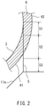
FIG. 2 , theskirt 5 includes anupper portion 51, amiddle portion 52, and alower portion 53. In the example shown, the upper andlower portions middle portion 52. However, the lengths of these portions may be changed as appropriate. - The
upper portion 51 is made of the same material as the tank body 3 (an example of the material is aluminum), and thelower portion 53 is made of the same material as the hull 11 (an example of the material is carbon steel). Themiddle portion 52 is made of a material having a lower heat conductivity than the materials of thetank body 3 and hull 11 (an example of the material of themiddle portion 52 is stainless steel). Although not shown, joints for dissimilar materials are disposed between the upper andmiddle portions lower portions - In the present embodiment, the
heat insulator 6 is composed of foamed materials arranged adjacent to one another, each of the foamed materials being shaped as a panel. The foamed materials are made of a resin such as polyurethane (PU) or phenolic resin (PF). - The
membrane 4 hermetically covers theheat insulator 6 along the outer surface of thetank body 3. That is, the shape of themembrane 4 is similar to the shape of thetank body 3. Themembrane 4 is significantly thinner than thetank body 3, and thus cannot support itself unlike thetank body 3. The thickness of themembrane 4 is, for example, equal to or smaller than 1/10 of the thickness of thetank body 3. For example, the thickness of thetank body 3 is from 10 to 80 mm, and the thickness of themembrane 4 is from 1 to 10 mm. - For example, the
membrane 4 may be made of invar alloy having an extremely low linear expansion coefficient or may be made of stainless steel. Themembrane 4 is desirably pleated to absorb the differential thermal shrinkage that thetank body 3 andmembrane 4 undergo upon introduction of the liquefied gas into thetank body 3. - The
membrane 4 is fixed to theheat insulator 6 or thetank body 3, with theheat insulator 6 held between thetank body 3 and themembrane 4. Both the upper and lower hemispherical portions of themembrane 4 are desirably fixed to theheat insulator 6 or thetank body 3. However, only the lower hemispherical portion of themembrane 4 may be fixed to theheat insulator 6 or thetank body 3. - For example, the
membrane 4 may be fixed to theheat insulator 6 during production of the foamed materials composing theheat insulator 6, and this fixing may be accomplished by self-adhesion occurring due to foaming of the resin. For example, in the case where theheat insulator 6 has a layered structure including a wire net held between the lower and upper foamed material layers, the wire net may be fixed using stud bolts disposed on the outer surface of thetank body 3, and the wire net and themembrane 4 may be coupled by bolts. Alternatively, themembrane 4 may be fixed directly to thetank body 3 using stud bolts having a length greater than the thickness of theheat insulator 6. - The
membrane 4 includes an innercurved portion 41 located inside theskirt 5 and an outercurved portion 42 located outside theskirt 5. Each of the inner and outercurved portions middle portion 52 of the skirt 5 (an example of the material is stainless steel). Each of the inner and outercurved portions middle portion 52 of theskirt 5 by means such as welding. - In the present embodiment, the space provided by the
heat insulator 6 between thetank body 3 and themembrane 4 is filled with nitrogen gas. The space between thetank body 3 and themembrane 4 may be filled with hydrogen gas or helium gas. - The pressure in the space between the
tank body 3 and themembrane 4 is lower than the atmospheric pressure. For example, the pressure in the space between thetank body 3 and themembrane 4 is from 1.0 × 10⁻⁵ to 5.0 × 10⁴ Pa. - One way of creating a negative-pressure nitrogen gas environment between the
tank body 3 and themembrane 4 as in the present embodiment may be to first suck in air present between thetank body 3 and themembrane 4 by a vacuum pump after production of thetank body 3 andmembrane 4, then inject nitrogen gas into the space between thetank body 3 and themembrane 4, and finally suck in the nitrogen gas by a vacuum pump. - In the liquefied
gas tank 2A of the present embodiment, as described above, theheat insulator 6 is hermetically covered by themembrane 4, and this makes it possible to fill the space between thetank body 3 and themembrane 4 with a gas other than air or decrease the pressure in the space below the atmospheric pressure. That is, the liquefiedgas tank 2A of the present embodiment has a feasible structure. - In the case where the pressure in the space between the
tank body 3 and themembrane 4 is equal to the atmospheric pressure, a large number of stud bolts for fixing are needed to allow theentire membrane 4 to adhere closely to theheat insulator 6. - In contrast, in the present embodiment, where the pressure in the space between the
tank body 3 and themembrane 4 is lower than the atmospheric pressure, themembrane 4 is pressed against thetank body 3 by the atmospheric pressure via theheat insulator 6. Thus, the structure for fixing themembrane 4 can be simplified, for example, by reducing the number of the stud bolts for fixing. This allows for a reduction in the number of heat penetration routes leading to thetank body 3, resulting in improved heat insulation performance. - Further, in the present embodiment, the upper and
lower portions skirt 5 are made of the same materials as thetank body 3 andhull 11, respectively. Thus, theskirt 5 can easily be joined to thetank body 3 andhull 11. Moreover, since themiddle portion 52 of theskirt 5 has a lower heat conductivity than the upper andlower portions skirt 5 can be hindered by themiddle portion 52. - Additionally, in the present embodiment, the inner and outer
curved portions membrane 4 are made of the same material as themiddle portion 52 of theskirt 5 and joined to themiddle portion 52. Thus, upon introduction of the liquefied gas into thetank body 3, each of the inner and outercurved portions curved portion heat insulator 6, with a ring-shaped junction with theskirt 5 serving as a base point of sticking. - The space between the
tank body 3 and themembrane 4 may be filled with a boil-off gas generated by evaporation of the liquefied gas stored in thetank body 3. Various methods can be used to fill the space between thetank body 3 and themembrane 4 with the boil-off gas. For example, an upper portion of thetank body 3 may be provided with a communication hole. Alternatively, although not shown, a delivery pipe through which the boil-off gas is delivered from thetank body 3 to another device may be provided with a branch pipe, and the distal end of the branch pipe may open into the space between thetank body 3 and themembrane 4. -
FIG. 3 shows the liquefied gas carrier ship 1 including a liquefiedgas tank 2B according to a second embodiment of the present invention. In the present embodiment, elements which are the same as those of the first embodiment are denoted by the same reference signs, and the descriptions given above for these elements are omitted. - In the present embodiment, the
heat insulator 6 entirely covers the inner surface, rather than the outer surface, of thetank body 3, and themembrane 4 covers theheat insulator 6 entirely and hermetically along the inner surface of thetank body 3. The liquefied gas is stored inside themembrane 4. - The
membrane 4 is fixed to theheat insulator 6 or thetank body 3, with theheat insulator 6 held between thetank body 3 and themembrane 4. Both the upper and lower hemispherical portions of themembrane 4 are desirably fixed to theheat insulator 6 or thetank body 3. However, only the upper hemispherical portion of themembrane 4 may be fixed to theheat insulator 6 or thetank body 3. - For example, the
membrane 4 may be fixed to theheat insulator 6 during production of the foamed materials composing theheat insulator 6, and this fixing may be accomplished by self-adhesion occurring due to foaming of the resin. For example, in the case where theheat insulator 6 has a layered structure including a wire net held between the lower and upper foamed material layers, the wire net may be fixed using stud bolts disposed on the inner surface of thetank body 3, and the wire net and themembrane 4 may be coupled by bolts. Alternatively, themembrane 4 may be fixed directly to thetank body 3 using stud bolts having a length greater than the thickness of theheat insulator 6. - In the present embodiment, the space provided by the
heat insulator 6 between thetank body 3 and themembrane 4 is filled with a boil-off gas generated by evaporation of the liquefied gas stored in themembrane 4. Various methods can be used to fill the space between thetank body 3 and themembrane 4 with the boil-off gas. For example, an upper portion of themembrane 4 may be provided with a communication hole. Alternatively, although not shown, a delivery pipe through which the boil-off gas is delivered from inside themembrane 4 to another device may be provided with a branch pipe, and the distal end of the branch pipe may open into the space between thetank body 3 and themembrane 4. - In the liquefied
gas tank 2B of the present embodiment, as in the liquefiedgas tank 2A of the first embodiment, theheat insulator 6 is hermetically covered by themembrane 4, and this makes it possible to fill the space between thetank body 3 and themembrane 4 with a gas other than air or decrease the pressure in the space below the ambient pressure. That is, the liquefiedgas tank 2B of the present embodiment has a feasible structure. - As shown in
FIG. 4 , the outer surface of thetank body 3 may be covered by aheat insulator 7. When the outer surface of thetank body 3 is bare as shown inFIG. 3 , the heat insulation performance needs to be ensured by increasing the distance from themembrane 4 to thetank body 3. In contrast, when the outer surface of thetank body 3 is covered by theheat insulator 7 as shown inFIG. 4 , the distance from themembrane 4 to thetank body 3 and hence the diameter of thetank body 3 can be smaller than when the outer surface of thetank body 3 is not covered by theheat insulator 7. - In the case where the
heat insulator 7 is a foamed material, since the holdingspace 13 located outside theheat insulator 7 is filled with nitrogen gas, the nitrogen gas enters theheat insulator 7 from the holdingspace 13, and the internal pores of theheat insulator 7 are filled with the nitrogen gas. Nitrogen gas may be fed to the second heat insulator 8 from a gas generator (not shown). In the case where the holdingspace 13 is filled with dry air rather than nitrogen gas, the internal pores of theheat insulator 7 may also be filled with dry air. - The present invention is not limited to the embodiments described above, and various modifications can be made without departing from the gist of the present invention.
- For example, the liquefied
gas tanks -
- 1
- liquefied gas carrier ship
- 2A, 2B
- liquefied gas tank
- 3
- tank body
- 4
- membrane
- 41
- inner curved portion
- 42
- outer curved portion
- 5
- skirt
- 51
- upper portion
- 52
- middle portion
- 53
- lower portion
- 6, 7
- heat insulator
Claims (11)
- A liquefied gas tank comprising:a spherical tank body storing a liquefied gas;a heat insulator covering an outer surface of the tank body; anda membrane hermetically covering the heat insulator along the outer surface of the tank body, the membrane being fixed to the heat insulator or the tank body, with the heat insulator held between the membrane and the tank body.
- The liquefied gas tank according to claim 1, wherein both upper and lower hemispherical portions of the membrane are fixed to the heat insulator or the tank body.
- The double-shell tank according to claim 1 or 2, further comprising a tubular skirt supporting the tank body on a floor surface of a hull, wherein
the skirt includes an upper portion made of the same material as the tank body, a lower portion made of the same material as the hull, and a middle portion made of a material having a lower heat conductivity than the materials of the tank body and the hull. - The double-shell tank according to claim 3, whereinthe membrane includes an inner curved portion located inside the skirt and an outer curved portion located outside the skirt, andeach of the inner and outer curved portions is made of the same material as the middle portion of the skirt and joined to the middle portion of the skirt.
- The liquefied gas tank according to any one of claims 1 to 4, wherein a pressure in a space provided by the heat insulator between the tank body and the membrane is lower than an atmospheric pressure.
- The liquefied gas tank according to any one of claims 1 to 4, wherein a space provided by the heat insulator between the tank body and the membrane is filled with a boil-off gas generated by evaporation of the liquefied gas.
- A liquefied gas tank comprising:a spherical tank body;a heat insulator covering an inner surface of the tank body; anda membrane hermetically covering the heat insulator along the inner surface of the tank body, the membrane being fixed to the heat insulator or the tank body, with the heat insulator held between the membrane and the tank body, whereinthe liquefied gas is stored inside the membrane.
- The liquefied gas tank according to claim 7, wherein both upper and lower hemispherical portions of the membrane are fixed to the heat insulator or the tank body.
- The liquefied gas tank according to claim 7 or 8, wherein a space provided by the heat insulator between the tank body and the membrane is filled with a boil-off gas generated by evaporation of the liquefied gas.
- The liquefied gas tank according to any one of claims 7 to 9, further comprising a heat insulator covering an outer surface of the tank body.
- A liquefied gas carrier ship comprising the liquefied gas tank according to any one of claims 1 to 10.
Applications Claiming Priority (1)
| Application Number | Priority Date | Filing Date | Title |
|---|---|---|---|
| PCT/JP2019/015228 WO2020202579A1 (en) | 2019-04-05 | 2019-04-05 | Liquefied gas tank and liquefied gas carrying vessel |
Publications (3)
| Publication Number | Publication Date |
|---|---|
| EP3950536A1 true EP3950536A1 (en) | 2022-02-09 |
| EP3950536A4 EP3950536A4 (en) | 2022-11-30 |
| EP3950536B1 EP3950536B1 (en) | 2026-05-20 |
Family
ID=72666524
Family Applications (1)
| Application Number | Title | Priority Date | Filing Date |
|---|---|---|---|
| EP19923070.7A Active EP3950536B1 (en) | 2019-04-05 | 2019-04-05 | LIQUID GAS TANK AND LIQUID GAS TANK VESSEL |
Country Status (5)
| Country | Link |
|---|---|
| EP (1) | EP3950536B1 (en) |
| JP (1) | JP7312815B2 (en) |
| KR (1) | KR102662477B1 (en) |
| CN (1) | CN113661134B (en) |
| WO (1) | WO2020202579A1 (en) |
Cited By (3)
| Publication number | Priority date | Publication date | Assignee | Title |
|---|---|---|---|---|
| US11933435B2 (en) | 2021-10-08 | 2024-03-19 | Toyota Jidosha Kabushiki Kaisha | High-pressure gas tank connection structure |
| NO20221390A1 (en) * | 2022-12-22 | 2024-06-24 | Moss Maritime As | Liquified gas storage tank |
| EP4397600A4 (en) * | 2021-09-03 | 2025-08-20 | Kawasaki Heavy Ind Ltd | LIQUID HYDROGEN TANK AND METHOD FOR DESIGNING SAME |
Families Citing this family (4)
| Publication number | Priority date | Publication date | Assignee | Title |
|---|---|---|---|---|
| JP7527107B2 (en) | 2019-12-27 | 2024-08-02 | 三菱造船株式会社 | Cargo tank unit and ship |
| WO2022144971A1 (en) * | 2020-12-28 | 2022-07-07 | 川崎重工業株式会社 | Multi-shell tank and vessel |
| KR102559317B1 (en) * | 2021-11-03 | 2023-07-26 | 한화오션 주식회사 | N2 Purging System And Method For Reliquefaction Apparatus In Ship |
| WO2024062624A1 (en) * | 2022-09-22 | 2024-03-28 | 川崎重工業株式会社 | Multiple-wall tank and vessel |
Family Cites Families (21)
| Publication number | Priority date | Publication date | Assignee | Title |
|---|---|---|---|---|
| NO743932L (en) * | 1974-10-31 | 1976-05-03 | Moss Rosenberg Verft As | |
| JPH07217796A (en) * | 1994-01-28 | 1995-08-15 | Mitsubishi Heavy Ind Ltd | Membrane fixing structure for low temperature tank |
| JP3428748B2 (en) * | 1994-11-16 | 2003-07-22 | 株式会社アイ・エイチ・アイ マリンユナイテッド | Freestanding square tank for liquid carrier |
| JP2720322B2 (en) * | 1995-02-23 | 1998-03-04 | 川崎重工業株式会社 | Heat insulation structure for cryogenic tank |
| JPH1182889A (en) * | 1997-09-10 | 1999-03-26 | I H I Plantec:Kk | Vertical insulated cryogenic tank |
| JP4431842B2 (en) * | 1998-03-31 | 2010-03-17 | 株式会社石井鐵工所 | Inner tank support structure of double shell spherical storage tank |
| JP2004028238A (en) * | 2002-06-26 | 2004-01-29 | Mitsubishi Heavy Ind Ltd | Tank |
| JP3866228B2 (en) * | 2003-07-10 | 2007-01-10 | 株式会社新来島どっく | Liquefied DME gas carrier and liquefied DME gas tank cooling system |
| JP4513435B2 (en) * | 2003-07-16 | 2010-07-28 | 東京エレクトロン株式会社 | Transport device |
| JP5403900B2 (en) * | 2007-11-16 | 2014-01-29 | 三菱重工業株式会社 | Liquefied gas carrier |
| JP5153416B2 (en) * | 2008-03-31 | 2013-02-27 | 三井造船株式会社 | Ship |
| JP6390009B2 (en) * | 2013-03-01 | 2018-09-19 | パナソニックIpマネジメント株式会社 | Insulated container |
| CN104100832A (en) * | 2013-04-10 | 2014-10-15 | 荆门宏图特种飞行器制造有限公司 | Low temperature double casing spherical storage tank with combination support mechanism |
| JP6381872B2 (en) * | 2013-07-03 | 2018-08-29 | 信吉 森元 | Long ocean floating facility |
| GB2535397B (en) * | 2014-02-28 | 2017-10-04 | Mgi Thermo Pte Ltd | An LNG fuel containment apparatus incorporating multi-layered insulation panels |
| JP6277554B2 (en) * | 2014-07-10 | 2018-02-14 | 三菱重工業株式会社 | Carrier ship |
| JP6364694B2 (en) * | 2014-07-10 | 2018-08-01 | 三菱造船株式会社 | Carrier ship |
| KR101589118B1 (en) * | 2014-07-30 | 2016-01-27 | 삼성중공업 주식회사 | Pressurized container for liquefied gas |
| EP3239589A4 (en) * | 2014-12-26 | 2017-12-13 | Panasonic Intellectual Property Management Co., Ltd. | Heat-insulating container provided with vacuum heat-insulating material, vacuum heat-insulating material, and tanker provided with heat-insulating container |
| KR102593666B1 (en) * | 2015-12-22 | 2023-10-24 | 쉘 인터내셔날 리써취 마트샤피지 비.브이. | Ship containment system for liquified gases |
| JP6535928B2 (en) * | 2016-05-16 | 2019-07-03 | 三菱造船株式会社 | Liquefied gas quenchability determination device, liquefied gas storage tank, liquefied gas carrier, and quenchability determination method by liquefied gas |
-
2019
- 2019-04-05 CN CN201980095139.XA patent/CN113661134B/en active Active
- 2019-04-05 KR KR1020217033825A patent/KR102662477B1/en active Active
- 2019-04-05 EP EP19923070.7A patent/EP3950536B1/en active Active
- 2019-04-05 WO PCT/JP2019/015228 patent/WO2020202579A1/en not_active Ceased
- 2019-04-05 JP JP2021511075A patent/JP7312815B2/en active Active
Cited By (4)
| Publication number | Priority date | Publication date | Assignee | Title |
|---|---|---|---|---|
| EP4397600A4 (en) * | 2021-09-03 | 2025-08-20 | Kawasaki Heavy Ind Ltd | LIQUID HYDROGEN TANK AND METHOD FOR DESIGNING SAME |
| US11933435B2 (en) | 2021-10-08 | 2024-03-19 | Toyota Jidosha Kabushiki Kaisha | High-pressure gas tank connection structure |
| NO20221390A1 (en) * | 2022-12-22 | 2024-06-24 | Moss Maritime As | Liquified gas storage tank |
| NO348617B1 (en) * | 2022-12-22 | 2025-03-31 | Moss Maritime As | A liquefied gas storage tank and a method for manufacturing said tank |
Also Published As
| Publication number | Publication date |
|---|---|
| JPWO2020202579A1 (en) | 2020-10-08 |
| KR102662477B1 (en) | 2024-05-03 |
| EP3950536A4 (en) | 2022-11-30 |
| CN113661134B (en) | 2023-03-10 |
| CN113661134A (en) | 2021-11-16 |
| JP7312815B2 (en) | 2023-07-21 |
| WO2020202579A1 (en) | 2020-10-08 |
| EP3950536B1 (en) | 2026-05-20 |
| KR20210141628A (en) | 2021-11-23 |
Similar Documents
| Publication | Publication Date | Title |
|---|---|---|
| KR102662477B1 (en) | Liquefied gas tank and liquefied gas carrier | |
| CN113661355B (en) | Double-shell tank and liquefied gas carrying ship | |
| US7775391B2 (en) | Container for holding a cryogenic fuel | |
| US6347719B1 (en) | Light weight hydrogen tank | |
| US20140166662A1 (en) | Suspension System for a Cryogenic Vessel | |
| US5419139A (en) | Composite cryogenic tank apparatus | |
| EP3012509B1 (en) | Double-shell tank and liquefied gas carrier ship | |
| EP3904196B1 (en) | Ship | |
| JP2019501064A5 (en) | ||
| EP3951244B1 (en) | Liquefied gas storage structure and liquefied gas carrier ship | |
| JP2022103917A (en) | Triple shell tank | |
| RU2717931C1 (en) | Low-temperature reservoir and method of its production | |
| KR102340889B1 (en) | Double shell tanks and liquefied gas carriers | |
| KR20220122417A (en) | The insulation methods for liquid hydrogen(LN2) storage tanks | |
| JP7723493B2 (en) | Double-hulled tanks and ships | |
| KR20230147673A (en) | Multi-angle tanks and ships | |
| JP2022035616A (en) | Liquified gas carrier | |
| KR830000804B1 (en) | Insulated marine container for liquefied gas | |
| KR20250179184A (en) | Pump tower base support for liquefied gas storage tank | |
| KR20230057272A (en) | Cryogenic tank for storing liquefied fluid |
Legal Events
| Date | Code | Title | Description |
|---|---|---|---|
| STAA | Information on the status of an ep patent application or granted ep patent |
Free format text: STATUS: THE INTERNATIONAL PUBLICATION HAS BEEN MADE |
|
| PUAI | Public reference made under article 153(3) epc to a published international application that has entered the european phase |
Free format text: ORIGINAL CODE: 0009012 |
|
| STAA | Information on the status of an ep patent application or granted ep patent |
Free format text: STATUS: REQUEST FOR EXAMINATION WAS MADE |
|
| 17P | Request for examination filed |
Effective date: 20211105 |
|
| AK | Designated contracting states |
Kind code of ref document: A1 Designated state(s): AL AT BE BG CH CY CZ DE DK EE ES FI FR GB GR HR HU IE IS IT LI LT LU LV MC MK MT NL NO PL PT RO RS SE SI SK SM TR |
|
| DAV | Request for validation of the european patent (deleted) | ||
| DAX | Request for extension of the european patent (deleted) | ||
| A4 | Supplementary search report drawn up and despatched |
Effective date: 20221027 |
|
| RIC1 | Information provided on ipc code assigned before grant |
Ipc: F17C 3/02 20060101ALI20221021BHEP Ipc: B65D 90/06 20060101AFI20221021BHEP |
|
| STAA | Information on the status of an ep patent application or granted ep patent |
Free format text: STATUS: EXAMINATION IS IN PROGRESS |
|
| 17Q | First examination report despatched |
Effective date: 20240625 |
|
| GRAP | Despatch of communication of intention to grant a patent |
Free format text: ORIGINAL CODE: EPIDOSNIGR1 |
|
| STAA | Information on the status of an ep patent application or granted ep patent |
Free format text: STATUS: GRANT OF PATENT IS INTENDED |
|
| INTG | Intention to grant announced |
Effective date: 20260209 |
|
| GRAS | Grant fee paid |
Free format text: ORIGINAL CODE: EPIDOSNIGR3 |
|
| GRAA | (expected) grant |
Free format text: ORIGINAL CODE: 0009210 |
|
| STAA | Information on the status of an ep patent application or granted ep patent |
Free format text: STATUS: THE PATENT HAS BEEN GRANTED |
|
| AK | Designated contracting states |
Kind code of ref document: B1 Designated state(s): AL AT BE BG CH CY CZ DE DK EE ES FI FR GB GR HR HU IE IS IT LI LT LU LV MC MK MT NL NO PL PT RO RS SE SI SK SM TR |
|
| REG | Reference to a national code |
Ref country code: CH Ref legal event code: F10 Free format text: ST27 STATUS EVENT CODE: U-0-0-F10-F00 (AS PROVIDED BY THE NATIONAL OFFICE) Effective date: 20260520 Ref country code: GB Ref legal event code: FG4D |
|
| REG | Reference to a national code |
Ref country code: DE Ref legal event code: R096 Ref document number: 602019085115 Country of ref document: DE |