EP3950527A1 - Cap for a container and related production method - Google Patents
Cap for a container and related production method Download PDFInfo
- Publication number
- EP3950527A1 EP3950527A1 EP21189466.2A EP21189466A EP3950527A1 EP 3950527 A1 EP3950527 A1 EP 3950527A1 EP 21189466 A EP21189466 A EP 21189466A EP 3950527 A1 EP3950527 A1 EP 3950527A1
- Authority
- EP
- European Patent Office
- Prior art keywords
- cup
- shaped body
- cap
- container
- recess
- Prior art date
- Legal status (The legal status is an assumption and is not a legal conclusion. Google has not performed a legal analysis and makes no representation as to the accuracy of the status listed.)
- Granted
Links
Images



Classifications
-
- B—PERFORMING OPERATIONS; TRANSPORTING
- B65—CONVEYING; PACKING; STORING; HANDLING THIN OR FILAMENTARY MATERIAL
- B65D—CONTAINERS FOR STORAGE OR TRANSPORT OF ARTICLES OR MATERIALS, e.g. BAGS, BARRELS, BOTTLES, BOXES, CANS, CARTONS, CRATES, DRUMS, JARS, TANKS, HOPPERS, FORWARDING CONTAINERS; ACCESSORIES, CLOSURES, OR FITTINGS THEREFOR; PACKAGING ELEMENTS; PACKAGES
- B65D65/00—Wrappers or flexible covers; Packaging materials of special type or form
- B65D65/38—Packaging materials of special type or form
- B65D65/46—Applications of disintegrable, dissolvable or edible materials
- B65D65/466—Bio- or photodegradable packaging materials
-
- B—PERFORMING OPERATIONS; TRANSPORTING
- B65—CONVEYING; PACKING; STORING; HANDLING THIN OR FILAMENTARY MATERIAL
- B65D—CONTAINERS FOR STORAGE OR TRANSPORT OF ARTICLES OR MATERIALS, e.g. BAGS, BARRELS, BOTTLES, BOXES, CANS, CARTONS, CRATES, DRUMS, JARS, TANKS, HOPPERS, FORWARDING CONTAINERS; ACCESSORIES, CLOSURES, OR FITTINGS THEREFOR; PACKAGING ELEMENTS; PACKAGES
- B65D41/00—Caps, e.g. crown caps or crown seals, i.e. members having parts arranged for engagement with the external periphery of a neck or wall defining a pouring opening or discharge aperture; Protective cap-like covers for closure members, e.g. decorative covers of metal foil or paper
- B65D41/02—Caps or cap-like covers without lines of weakness, tearing strips, tags, or like opening or removal devices
- B65D41/04—Threaded or like caps or cap-like covers secured by rotation
-
- B—PERFORMING OPERATIONS; TRANSPORTING
- B29—WORKING OF PLASTICS; WORKING OF SUBSTANCES IN A PLASTIC STATE IN GENERAL
- B29D—PRODUCING PARTICULAR ARTICLES FROM PLASTICS OR FROM SUBSTANCES IN A PLASTIC STATE
- B29D99/00—Subject matter not provided for in other groups of this subclass
- B29D99/0096—Producing closure members for containers, e.g. closure caps or stoppers
-
- B—PERFORMING OPERATIONS; TRANSPORTING
- B65—CONVEYING; PACKING; STORING; HANDLING THIN OR FILAMENTARY MATERIAL
- B65D—CONTAINERS FOR STORAGE OR TRANSPORT OF ARTICLES OR MATERIALS, e.g. BAGS, BARRELS, BOTTLES, BOXES, CANS, CARTONS, CRATES, DRUMS, JARS, TANKS, HOPPERS, FORWARDING CONTAINERS; ACCESSORIES, CLOSURES, OR FITTINGS THEREFOR; PACKAGING ELEMENTS; PACKAGES
- B65D41/00—Caps, e.g. crown caps or crown seals, i.e. members having parts arranged for engagement with the external periphery of a neck or wall defining a pouring opening or discharge aperture; Protective cap-like covers for closure members, e.g. decorative covers of metal foil or paper
- B65D41/32—Caps or cap-like covers with lines of weakness, tearing-strips, tags, or like opening or removal devices, e.g. to facilitate formation of pouring openings
- B65D41/325—Caps or cap-like covers with lines of weakness, tearing-strips, tags, or like opening or removal devices, e.g. to facilitate formation of pouring openings with integral internal sealing means
-
- B—PERFORMING OPERATIONS; TRANSPORTING
- B65—CONVEYING; PACKING; STORING; HANDLING THIN OR FILAMENTARY MATERIAL
- B65D—CONTAINERS FOR STORAGE OR TRANSPORT OF ARTICLES OR MATERIALS, e.g. BAGS, BARRELS, BOTTLES, BOXES, CANS, CARTONS, CRATES, DRUMS, JARS, TANKS, HOPPERS, FORWARDING CONTAINERS; ACCESSORIES, CLOSURES, OR FITTINGS THEREFOR; PACKAGING ELEMENTS; PACKAGES
- B65D41/00—Caps, e.g. crown caps or crown seals, i.e. members having parts arranged for engagement with the external periphery of a neck or wall defining a pouring opening or discharge aperture; Protective cap-like covers for closure members, e.g. decorative covers of metal foil or paper
- B65D41/32—Caps or cap-like covers with lines of weakness, tearing-strips, tags, or like opening or removal devices, e.g. to facilitate formation of pouring openings
- B65D41/34—Threaded or like caps or cap-like covers provided with tamper elements formed in, or attached to, the closure skirt
- B65D41/3423—Threaded or like caps or cap-like covers provided with tamper elements formed in, or attached to, the closure skirt with flexible tabs, or elements rotated from a non-engaging to an engaging position, formed on the tamper element or in the closure skirt
- B65D41/3428—Threaded or like caps or cap-like covers provided with tamper elements formed in, or attached to, the closure skirt with flexible tabs, or elements rotated from a non-engaging to an engaging position, formed on the tamper element or in the closure skirt the tamper element being integrally connected to the closure by means of bridges
-
- B—PERFORMING OPERATIONS; TRANSPORTING
- B65—CONVEYING; PACKING; STORING; HANDLING THIN OR FILAMENTARY MATERIAL
- B65D—CONTAINERS FOR STORAGE OR TRANSPORT OF ARTICLES OR MATERIALS, e.g. BAGS, BARRELS, BOTTLES, BOXES, CANS, CARTONS, CRATES, DRUMS, JARS, TANKS, HOPPERS, FORWARDING CONTAINERS; ACCESSORIES, CLOSURES, OR FITTINGS THEREFOR; PACKAGING ELEMENTS; PACKAGES
- B65D41/00—Caps, e.g. crown caps or crown seals, i.e. members having parts arranged for engagement with the external periphery of a neck or wall defining a pouring opening or discharge aperture; Protective cap-like covers for closure members, e.g. decorative covers of metal foil or paper
- B65D41/32—Caps or cap-like covers with lines of weakness, tearing-strips, tags, or like opening or removal devices, e.g. to facilitate formation of pouring openings
- B65D41/34—Threaded or like caps or cap-like covers provided with tamper elements formed in, or attached to, the closure skirt
- B65D41/3442—Threaded or like caps or cap-like covers provided with tamper elements formed in, or attached to, the closure skirt with rigid bead or projections formed on the tamper element and coacting with bead or projections on the container
- B65D41/3447—Threaded or like caps or cap-like covers provided with tamper elements formed in, or attached to, the closure skirt with rigid bead or projections formed on the tamper element and coacting with bead or projections on the container the tamper element being integrally connected to the closure by means of bridges
-
- B—PERFORMING OPERATIONS; TRANSPORTING
- B65—CONVEYING; PACKING; STORING; HANDLING THIN OR FILAMENTARY MATERIAL
- B65D—CONTAINERS FOR STORAGE OR TRANSPORT OF ARTICLES OR MATERIALS, e.g. BAGS, BARRELS, BOTTLES, BOXES, CANS, CARTONS, CRATES, DRUMS, JARS, TANKS, HOPPERS, FORWARDING CONTAINERS; ACCESSORIES, CLOSURES, OR FITTINGS THEREFOR; PACKAGING ELEMENTS; PACKAGES
- B65D43/00—Lids or covers for rigid or semi-rigid containers
- B65D43/02—Removable lids or covers
- B65D43/0202—Removable lids or covers without integral tamper element
- B65D43/0204—Removable lids or covers without integral tamper element secured by snapping over beads or projections
-
- B—PERFORMING OPERATIONS; TRANSPORTING
- B65—CONVEYING; PACKING; STORING; HANDLING THIN OR FILAMENTARY MATERIAL
- B65D—CONTAINERS FOR STORAGE OR TRANSPORT OF ARTICLES OR MATERIALS, e.g. BAGS, BARRELS, BOTTLES, BOXES, CANS, CARTONS, CRATES, DRUMS, JARS, TANKS, HOPPERS, FORWARDING CONTAINERS; ACCESSORIES, CLOSURES, OR FITTINGS THEREFOR; PACKAGING ELEMENTS; PACKAGES
- B65D55/00—Accessories for container closures not otherwise provided for
-
- B—PERFORMING OPERATIONS; TRANSPORTING
- B29—WORKING OF PLASTICS; WORKING OF SUBSTANCES IN A PLASTIC STATE IN GENERAL
- B29K—INDEXING SCHEME ASSOCIATED WITH SUBCLASSES B29B, B29C OR B29D, RELATING TO MOULDING MATERIALS OR TO MATERIALS FOR MOULDS, REINFORCEMENTS, FILLERS OR PREFORMED PARTS, e.g. INSERTS
- B29K2001/00—Use of cellulose, modified cellulose or cellulose derivatives, e.g. viscose, as moulding material
-
- B—PERFORMING OPERATIONS; TRANSPORTING
- B29—WORKING OF PLASTICS; WORKING OF SUBSTANCES IN A PLASTIC STATE IN GENERAL
- B29K—INDEXING SCHEME ASSOCIATED WITH SUBCLASSES B29B, B29C OR B29D, RELATING TO MOULDING MATERIALS OR TO MATERIALS FOR MOULDS, REINFORCEMENTS, FILLERS OR PREFORMED PARTS, e.g. INSERTS
- B29K2105/00—Condition, form or state of moulded material or of the material to be shaped
- B29K2105/06—Condition, form or state of moulded material or of the material to be shaped containing reinforcements, fillers or inserts
-
- B—PERFORMING OPERATIONS; TRANSPORTING
- B65—CONVEYING; PACKING; STORING; HANDLING THIN OR FILAMENTARY MATERIAL
- B65D—CONTAINERS FOR STORAGE OR TRANSPORT OF ARTICLES OR MATERIALS, e.g. BAGS, BARRELS, BOTTLES, BOXES, CANS, CARTONS, CRATES, DRUMS, JARS, TANKS, HOPPERS, FORWARDING CONTAINERS; ACCESSORIES, CLOSURES, OR FITTINGS THEREFOR; PACKAGING ELEMENTS; PACKAGES
- B65D2251/00—Details relating to container closures
- B65D2251/06—Special configurations; Closures simulating or provided with another item, e.g. puppet, animal, vehicle, building
Definitions
- the invention relates to a cap for a container made of a material at least part of which is derived from natural fibres, for example a material comprising cellulose.
- the cap according to the invention is intended to be used for closing containers such as bottles, jars, pots or the like.
- the invention also relates to a method for producing a cap for a container.
- natural and renewable materials for example cellulose-based materials, for producing packaging components, such as caps for containers.
- materials are much less polluting and easier to dispose of than synthetic polymers which are currently widely used in the packaging sector.
- Materials derived from natural fibres such as cellulose-based materials may be used for producing objects by moulding.
- the material deriving from natural fibres for example in the form of powder or in a pasty form, is positioned in a mould with a very low initial density and needs to be pressed with a high degree of compaction to provide a good quality object.
- caps often have considerable differences in thickness between one zone and another.
- many caps comprise, on an inner surface of their lateral wall, one or more threads which project inwards towards the inside the cap. At the threads, the lateral wall is thicker than it is in the zones in which the threads are not present.
- the variations in density in the cap may cause variations in the mechanical strength of the zones involved, with subsequent risks of breakage or excessive deformation in the less compacted zones.
- An object of the invention is to improve caps for containers, in particular caps made of a material at least part of which is derived from natural fibres, such as cellulose, as well as the related production methods.
- a further object is to provide a cap for a container made of a material at least part of which is derived from natural fibres, which has a substantially uniform density.
- Another object is to provide a cap for a container made of a material at least part of which is derived from natural fibres, which has mechanical properties which are as far as possible constant in different zones of the cap.
- a cap for a container is provided, the cap being made of a material at least part of which is derived from natural fibres, the cap comprising a cup-shaped body having a skirt which extends around an axis and a transversal wall arranged transversally to the axis, a cavity being defined inside the cup-shaped body, the cup-shaped body being delimited by an inner surface facing the cavity and by an outer surface facing the opposite way to the cavity, wherein at least one projecting element projects from a surface of the cup-shaped body selected from either the inner surface or the outer surface, and wherein at least one recess is provided at said at least one projecting element on another surface of the cup-shaped body selected from either the outer surface or the inner surface.
- the thickness of the cup-shaped body at the projecting element will be less than it would be if the recess were not present.
- the recess By suitably dimensioning the recess, it is possible to ensure that the thickness of the cup-shaped body does not vary excessively between the projecting element and the zones adjacent to it, that is to say, the thickness has reduced variability between different zones of the cap or is even substantially constant.
- the cap according to the first aspect of the invention has an outer three-dimensional profile which as far as possible copies the inner three-dimensional profile. That makes it possible to compact the material of which the cap is constituted with a uniform degree of compaction, avoiding the presence in the cap of zones having a density that is too low. In other words, in the cap according to the first aspect of the invention the density is maximised substantially in the whole cup-shaped body, depending on the compaction technology used.
- the projecting element is a fastening element which projects from the skirt inwards towards the inside of the cup-shaped body, that is to say, towards the cavity.
- the fastening element allows the cap or part of it to be removably fixed to a neck of the container, so that the cap can be applied to the neck of the container and then removed from the latter.
- the fastening element may be a screw thread, suitable for engaging with a corresponding screw thread made on the neck of the container.
- Providing a recess on the outer surface of the cup-shaped body at the fastening element avoids having a thickening of the cup-shaped body in the region in which the fastening element is located. In this way, the density of the material which constitutes the cap does not vary excessively between the region in which the fastening element is located and adjacent regions.
- provided on the skirt is an intended separating line which on the cup-shaped body defines a closing element and an annular band.
- the annular band is intended to remain anchored to a neck of the container.
- the closing element is intended to be separated from the annular band along the intended separating line to open the container to which the cap is applied.
- the closing element comprises a lateral wall which extends between the intended separating line and the transversal wall.
- the projecting element is an engaging element which projects from the annular band inwards towards the inside of the cup-shaped body, to engage with a retaining element provided on the neck of the container.
- the retaining element engaging with the engaging element, obstructs removal of the annular band from the neck of the container.
- the projecting element is an annular sealing element which from the transversal wall projects inwards towards the inside of the cup-shaped body for sealingly engaging with the neck of the container.
- Providing a recess on the outer surface of the cup-shaped body at the annular sealing element avoids having a thickening of the cup-shaped body in the region in which the annular sealing element is located. In this way, the density of the material which constitutes the cap does not vary excessively between the region in which the annular sealing element is located and adjacent regions.
- a method for producing a cap comprising a cup-shaped body inside which a cavity is defined, the cup-shaped body being delimited by an inner surface facing towards the cavity and by an outer surface facing the opposite way to the cavity, wherein the cap is produced during a step of pressing a material at least part of which is derived from natural fibres, the pressing step comprising forming at least one projecting element on a surface of the cup-shaped body selected from either the inner surface or the outer surface, and forming at least one recess at said at least one projecting element, on another surface of the cup-shaped body selected from either the outer surface or the inner surface, thereby minimising the differences in compaction between separate zones of the cup-shaped body.
- the material which is pressed to produce the cap is a dry material, for example in the form or powder or granules.
- the material which is pressed to produce the cap is in a pasty form.
- the material which is pressed to produce the cap may also be in the form of a solid film, or in a "fluff" type of form.
- the material at least part of which is derived from natural fibres may comprise cellulose.
- the material used to make the cap 1 may comprise a material derived from natural fibres, to which additives such as dyes, adhesives, lubricants and others have been added if necessary.
- the material used to make the cap 1 may comprise a material derived from natural fibres, mixed with a natural or synthetic polymeric material.
- the cap 1 comprises a cup-shaped body 2, inside which a cavity 3 is defined.
- the cup-shaped body 2 has an inner surface 4, facing the cavity 3 so as to delimit the cavity 3, and an outer surface 5, facing outwards from the cup-shaped body 2, that is to say facing away from the cavity 3.
- the cup-shaped body 2 comprises a skirt 6, which extends around an axis Z.
- the skirt 6 has a substantially cylindrical shape.
- the cup-shaped body 2 further comprises a transversal wall 7, which extends transversally, in particular perpendicularly, to the axis Z, at one end of the skirt 6.
- the transversal wall 7 may have a circular shape, if seen in plan view.
- the transversal wall 7 may be substantially flat, but this condition is not necessary.
- An intended separating line 10 is provided on the skirt 6 to define an annular band 8 and a closing element 9.
- the closing element 9 comprises the transversal wall 7 and a lateral wall 11 which extends around the axis Z.
- the lateral wall 11 is joined to the transversal wall 7 in a joining zone 12.
- the lateral wall 11 is a portion of the skirt 6 interposed between the transversal wall 7 and the intended separating line 10.
- the annular band 8 is a further portion of the skirt 6 and extends between the intended separating line 10 and a free edge 13 of the skirt 6.
- the intended separating line 10 may be parallel to the free edge 13 of the skirt 6. More generally, the intended separating line 10 may extend in a plane perpendicular to the axis Z.
- the closing element 9 Before the cap 1 is applied on the neck of the container, the closing element 9 is joined to the annular band 8 along the intended separating line 10. When the cap 1 is opened for the first time, the closing element 9 separates from the annular band 8 along the intended separating line 10. The closing element 9 may be removed from the container and subsequently re-applied on the related neck, whilst the annular band 8 remains anchored to the neck of the container after opening.
- the intended separating line 10 may comprise a plurality of breakable elements 14, which are separated from each other by interrupting segments 15 at which material is not present.
- the interrupting segments 15 may be cut segments obtained by cutting the skirt 6 after the cup-shaped body 2 has been formed. In this way, a breakable element 14 remains defined between two consecutive cut segments.
- the interrupting segments 15 may be obtained while the cap 1 is formed, in the same mould in which the cap 1 is shaped.
- the breakable elements 14 are intended to be broken the first time the closing element 9 is removed from the container to be brought into an open position.
- the lateral wall 11 has at least one fastening element 16 to allow the closing element 9 to be repeatedly fixed to the container and removed from the latter.
- the fastening element 16 has the shape of a projecting element which from the inner surface 4 projects inwards towards the inside of the cup-shaped body 2, that is to say, towards the cavity 3.
- the fastening element 16 is a screw thread suitable for engaging with a corresponding thread made on the neck of the container.
- the lateral wall 11 there may be a plurality of fastening elements 16, as in the example shown, in which there are two screw threads.
- a single fastening element 16 for example a single screw thread having an angular extent greater than the screw threads shown.
- the hollow 17 On the outer surface 5 of the cup-shaped body 2, at the fastening element 16 or at each fastening element 16, there is a hollow 17, that is to say, a recess which penetrates towards the inside of the cup-shaped body 2.
- the hollow 17 has a geometry which copies the geometry of the fastening element 16.
- the hollow 17 In the example shown, in cui which the fastening element 16 is a screw thread, the hollow 17 has a helical shape.
- the hollow 17 allows a reduction in the thickness of the lateral wall 11 at the fastening element 16, compared to the case in which the outer surface 5 were a smooth cylinder, that is to say, the hollow 17 were not present.
- the thickness of the lateral wall 11 in the region in which the fastening element 16 is present may be substantially constant.
- the number of hollows 17 is equal to the number of fastening elements 16. In the example shown, in which there are two fastening elements 16, the lateral wall 11 has two hollows 17.
- the annular band 8 may comprise at least one engaging element 18 suitable for engaging with a retaining element provided on the container.
- the retaining element is intended to keep the annular band 8 anchored to the container, preventing the annular band 8 from being able to be separated from the container when the closing element 9 is removed.
- Each engaging element 18 is shaped like a projecting element which projects inwards towards the inside of the cup-shaped body 2 from the annular band 8.
- each engaging element 18 has an abutting front surface 19, which may be substantially flat, suitable for abutting against a stop surface of the retaining element to prevent the annular band 8 from rotating further when the closing element 9 is unscrewed.
- the abutting front surface 19 may extend in a radial plane, that is to say, in a plane containing the axis Z.
- the engaging element 18 also has a rounded rear end 20.
- the engaging element 18 projects from the inner surface 4 by an amount which gradually decreases from the abutting front surface 19 to the rear end 20.
- the engaging element 18 may extend along a central line which lies in a plane perpendicular to the axis Z.
- engaging elements 18 there are three engaging elements 18, but the number of engaging elements 18 may be selected according to the particular type of container and the characteristics of the cap which must be applied to the container.
- the indentation 21 may have a shape similar to that of the engaging element 18.
- the indentation 21 allows a reduction in the thickness of the annular band 8 at the engaging element 18 compared to the thickness that the annular band 8 would have if the indentation 21 were not present.
- the thickness of the annular band 8 at the engaging element 18 may be substantially equal to, or in any case not too dissimilar from, the thickness of the annular band 8 outside of the engaging element 18.
- annular sealing element 22 which projects from the inner surface 4 towards the cavity 3, that is to say, inwards towards the inside of the cup-shaped body 2.
- the annular sealing element 22 is suitable for engaging with the container, in particular with an edge region of the neck of the container, so that the closing element 9 can close the container in a substantially sealed fashion.
- the annular sealing element 22 is suitable for penetrating inside the neck of the container to make contact with an inner surface of the neck.
- the annular sealing element 22 could be sized in such a way as to surround an edge of the neck of the container from the outside, so that it makes contact with an outer surface of the neck, near the rim of the latter.
- the annular sealing element 22 is shaped as a circular protuberance having a centre on the axis Z.
- the annular sealing element 22 may have a cross-section which is "U"-shaped or "V"-shaped with a rounded vertex, with walls which are not necessarily symmetrical. In this way, the annular sealing element 22 may be easily produced in a mould and extracted from the latter, since it is free of undercuts.
- annular groove 23 On the outer surface 5 of the cup-shaped body 2, more precisely on the transversal wall 7, there is an annular groove 23 which penetrates towards the inside of the cup-shaped body 2.
- the annular groove 23 has the shape of a recess positioned at the annular sealing element 22.
- the annular groove 23 has a geometry corresponding to the shape of the annular sealing element 22.
- the annular groove 23 is shaped like a circular groove centred on the axis Z.
- the material of the transversal wall 7 projects inwards towards the inside of the cup-shaped body 2 thereby defining the annular sealing element 22.
- the annular sealing element 22 is shaped like a corrugation which extends towards the cavity 3.
- the annular groove 23 prevents the creation of a thickening of the transversal wall 7 at the annular sealing element 22. In this way, it is possible to make the thickness of the transversal wall 7 more uniform even near the annular groove 23.
- the thickness of the transversal wall 7 must be constant.
- the transversal wall 7 in a central region thereof surrounded by the annular sealing element 22, the transversal wall 7 is thicker than the transversal wall 7 outside the annular sealing element 22. This makes the central part of the transversal wall 7 stiffer, reducing the risk that the transversal wall 7 can swell outwards from the cup-shaped body 2 or bend inwards towards the inside of the latter.
- the cap 1 may also comprise a plurality of gripping ribs 24, provided on the outer surface 5 to allow a user to more securely grasp the closing element 9, reducing the risk that the closing element 9 will slip whilst the user is handling it.
- the gripping ribs 24 also improve the grip on the cap 1 on a capping machine.
- the gripping ribs 24 may be provided on the lateral wall 11, near the joining zone 12.
- the gripping ribs 24 may in particular be interposed between the transversal wall 7 and the hollows 17, so that they do not interfere with the hollows 17.
- the gripping ribs 24 may be shaped like projecting lines which project outwards from the outer surface 5 of the cup-shaped body 2. In the example shown, the gripping ribs 24 project by a limited amount from outer surface 5. In this case, there are no recesses on the inner surface 4 at the gripping ribs 24.
- the gripping ribs 24 may be straight and extend parallel to the axis Z.
- the cap 1 is formed starting from a material at least part of which is derived from natural fibres, in the dry form (powder or granules), or in the pasty form, or also in the form of a solid film or in the form of a fluff. If the material used to form the cap is in the pasty form, it may be obtained by adding water or another liquid to a dry material.
- the material at least part of which is derived from natural fibres is introduced into a mould comprising a male mould-part and a female mould-part and compacted between the male part and the female part, which are moved one towards the other.
- the female part and/or the male part may comprise movable components which are movable to vary the volume of a forming chamber defined between the female part and the male part.
- the cup-shaped body 2 is obtained, by compression moulding.
- the outer surface 5 is shaped in such a way as to substantially copy the three-dimensional profile of the inner surface 4.
- the outer surface 5 is provided with recesses at the main projecting elements which project from the inner surface 4.
- the recesses of the outer surface 5 may comprise the hollows 17, and/or the indentations 21 and/or the annular groove 23. That allows the obtainment of the most uniform possible distribution of the density of the material at least part of which is derived from natural fibres in the cup-shaped body 2.
- the properties of the cap 1 are optimised.
- FIGs 5 and 6 show a cap 101 according to an alternative embodiment.
- the cap 101 differs from the cap 1 shown in Figures 1 to 4 mainly because it does not comprise the annular sealing element 22. Consequently, the transversal wall 7 may be free of recesses on its outer face 25 facing outwards from the cup-shaped body 2, that is to say, facing the opposite way to the cavity 4. That is to say, there is no annular groove 23.
- the transversal wall 7 may have a substantially constant thickness.
- the cap 101 may be used to close containers for which a hermetic seal is not essential, for example containers intended to contain substances which are not liquids and/or not foodstuffs.
- the cap 101 may exert a sealing action using additional sealing elements not shown, for example a seal applied on an inner face of the transversal wall 7.
- Figures 1 to 6 related to a screw cap
- Figures 7 to 9 show a different type of cap 201, more precisely a so-called “snap-on" cap intended to be applied using pressure on a neck of a container.
- the cap 201 comprises the cup-shaped body 2 on whose skirt 6 the intended separating line 10 is made, the intended separating line 10 defining the annular band 8 and the closing element 9, as already described with reference to Figures 1 to 6 .
- the intended separating line 10 there may be a plurality of breakable elements 14, intended to be broken the first time the closing element 9 is brought into an open position.
- the intended separating line 10 is circumferentially interrupted, so as to leave a connecting portion 26 which connects the closing element 9 to the annular band 8. Owing to the connecting portion 26, when the closing element 9 is brought into an open position, the closing element 9 remains attached to the annular band 8 and cannot be separated from the container to which the cap 201 is applied.
- the connecting portion 26 defines a hinge around which the closing element 9 can rotate to be brought into the open position.
- a recessed portion of wall 27 which penetrates towards the inside of the cup-shaped body 2 from outer surface 5.
- the recessed portion of wall 27 may extend at least from the connecting portion 26 as far as the transversal wall 7.
- the recessed portion of wall 27 allows the intended separating line 10 to be made more easily. If the latter is made using a cutting tool, the cutting tool may interact with the cap 201 over an angular extent of 360° around the axis Z. That is to say, there is no need for the cutting tool to operate in a way adjusted to the skirt 6, or interact with the skirt 6 only for a limited angular extent of the latter.
- the cutting tool does not cut the skirt 6 at the connecting portion 26, since it does not succeed in touching the material of the skirt 6 at the recessed portion of wall 27, which is closer to the axis Z than the regions of the skirt 6 adjacent to it.
- the lateral wall 11 of the closing element 9 projects towards the cavity 3, as shown in Figure 10 .
- the annular sealing element 22 which from the inner surface 4 projects inwards towards the inside of the cup-shaped body 2, that is to say, towards the cavity 3, as was the case in the cap 1.
- annular groove 23 which penetrates in the thickness of the transversal wall 7 on the outer surface 5, as already described with reference to Figures 1 to 4 .
- the annular sealing element 22 allows the closing element 9 to be kept in a closed position, by engaging with the neck of the container, in particular with an inner surface of the neck of the container. That is to say, the closing element 9 may remain in the closed position owing to the interference which is generated between the annular sealing element 22 and the neck of the container.
- the closing element 9 has a gripping tab 28 which projects outwards from the lateral wall 11.
- the gripping tab 28 extends transversally, in particular perpendicularly, to the axis Z.
- the gripping tab 28 may have a flat geometry.
- the gripping tab 28 is provided in a position diametrically opposite to the connecting portion 26.
- the user can act on the gripping tab 28, in particular on a lower surface of the latter, to more easily bring the closing element 9 into the open position.
- the user can also act on the gripping tab 28, in particular on an upper surface of the latter, to return the closing element 9 to the closed position.
- the annular band 8 is provided with a plurality of engaging elements 218 shaped like projecting elements, which from the inner surface 4 project towards the cavity 3, that is to say, inwards towards the inside of the cup-shaped body 2.
- the engaging elements 218 are intended to engage with at least one retaining element provided on the neck of the container and suitable for preventing the annular band 8 from being able to be removed from the neck.
- the retaining element may for example comprise an annular enlargement which projects outwards from the neck of the container.
- each indentation 221 being located at a respective engaging element 218.
- the indentations 221 have a shape corresponding to the shape of the engaging elements 218.
- the engaging elements 218 are functionally similar to the engaging elements 18 described with reference to the caps of Figures 1 to 6 , from which they differ in shape.
- the engaging elements 218 have the shape of circular arcs and extend along respective central lines lying in a plane positioned transversally, in particular perpendicularly, to the axis Z.
- Each engaging element 218 may have two rounded ends.
- the height of each engaging element 218 measured parallel to the axis Z may be constant at least in a central zone of the engaging element 218.
- the inner surface 4 there may be one or more fastening elements which project from the closing element 9 inwards towards the inside of the cup-shaped body 2, to more easily keep the closing element 9 in the closed position.
- the fastening elements may be shaped like elements projecting towards the cavity 3, not necessarily having the geometry of a screw thread.
- the fastening elements are intended to engage with corresponding fixing means provided on the neck of the container.
- Figures 11 to 13 show a cap 301 according to an alternative embodiment.
- the cap 301 is particularly suitable for closing containers which have a wide mouth, such as jars or pots.
- the cap 301 is a screw cap.
- the cap 301 does not comprise an annular band intended to remain anchored to a container neck.
- the cap 301 is brought into an open position, the whole cap 301 is removed from the neck of the container.
- the cap 301 is provided with a plurality of fastening elements 316 each of which is shaped like a projecting element which from the inner surface 4 projects inwards towards the inside of the cup-shaped body 2.
- Each fastening element 316 has the shape of a portion of screw thread.
- the thread-free gaps 29 correspond to smooth portions of the inner surface 4.
- the cap 301 comprises three fastening elements 316a, 316b, 316c belonging to the same screw thread, that is to say, positioned in sequence along the same helix which is wrapped around the axis Z.
- an initial portion of screw thread which during screwing is the first to engage with a corresponding thread of the container, is defined by the fastening element 316a.
- a final portion of screw thread which during screwing is the last to engage with the corresponding thread of the container, is defined by the fastening element 316c.
- An intermediate portion of screw thread is defined by the fastening element 316b, interposed between the fastening elements 316a and 316c.
- the fastening elements 316 present on the inner surface 4 may belong to multiple screw threads. In the example shown, there are three screw threads, distributed around the axis Z at an angular distance of 120* from each other. Each screw thread comprises a plurality of portions of thread (in the example shown, three portions of thread each of which is defined by respective fastening elements 316a, 316b, 316c).
- Fastening elements 316 belonging to different threads may be aligned along a direction parallel to the axis Z.
- the fastening element 316a corresponding to an initial portion of thread is aligned, along a direction parallel to the axis Z, with the fastening element 316c corresponding to a final portion of an adjacent thread.
- the fastening elements 316 are not present.
- the hollows 317 have a geometry similar to that of the fastening elements 316, that is to say, they are shaped like furrows which extend along a helix positioned around the axis Z.
- the hollows 317 allow a reduction in the thickness of the lateral wall 11 at the fastening elements 316 and therefore compacting of the material which forms the cap 301 with a substantially uniform density, even in the zones in which the fastening elements 316 are present.
- Each gripping rib 324 extends in a direction parallel to the axis Z.
- the gripping ribs 324 allow a user to securely grasp the cap 301 to screw it onto the container and unscrew it from the latter, preventing the cap 301 from slipping in the hands of the user. Moreover, the gripping ribs 324 make it easier for the cap 301 to be grasped on a capping machine.
- the gripping ribs 324 project by a limited amount from a cylindrical outer surface of the lateral wall 11.
- the increase in the thickness of the lateral wall 11 caused by the gripping ribs 324 is limited and does not negatively affect the cap 301.
- gripping ribs 324 were to project further from the lateral wall 11, on the inner surface 4 there could be recesses, in particular shaped like furrows, at the gripping ribs 324, so as to prevent excessive increases in the thickness of the lateral wall 11 at the gripping ribs 324 and to favour the most uniform possible compacting of the material of which the cap 301 is made.
- the transversal wall 7 of the cap 301 comprises a central panel 30 surrounded by a circular projection 31 which projects outwards from the cap 301.
- the central panel 30 has a circular shape concentric with the axis Z.
- the circular projection 31 is concentric with the central panel 30.
- the annular seat 32 is delimited by an outer lateral surface 33 and by an inner lateral surface 34 which are facing each other.
- the inner lateral surface 34 is a surface tilted relative to the axis Z
- the outer lateral surface 33 is a cylindrical surface which extends parallel to the axis Z.
- the inner lateral surface 34 and/or the outer lateral surface 33 may engage with the rim of the container, respectively on the inside and on the outside of the latter, to prevent a product contained in the container from coming out.
- an end surface 35 Interposed between the inner lateral surface 34 and the outer lateral surface 33 there may be an end surface 35 which extends transversally, in particular perpendicularly, to the axis Z.
- the end surface 35 is flat.
- the annular seat 32 is provided at the circular projection 31, the thickness of the transversal wall 7 does not undergo large variations, which allows the density of the cap 301 to be kept substantially uniform.
- gripping elements have been described comprising the gripping ribs 24 or 324, which extend in a direction parallel to the axis Z.
- the gripping elements may be shaped like gripping ribs extending obliquely relative to the axis Z. It is also possible to use gripping elements having a shape different from the gripping ribs, for example shaped like local protuberances which occupy a limited portion of the height of the skirt.
- the gripping elements may project outwards from the skirt, or they may penetrate towards the inside of the skirt. In both cases, the gripping elements create surface irregularities which make it easier to grasp the cap. If the gripping elements project outwards from the skirt, then on the inner surface of the cup-shaped body there may be recesses at the gripping elements. In contrast, if the gripping elements penetrate towards the inside of the skirt from the outer surface of the cup-shaped body, then on the inner surface of the cup-shaped body there may be projecting elements at the gripping elements.
- the caps described above may exert a sealing action, when they engage with the neck of the container, owing to additional sealing elements not shown, for example a seal applied on an inner face of the transversal wall 7.
Landscapes
- Engineering & Computer Science (AREA)
- Mechanical Engineering (AREA)
- Life Sciences & Earth Sciences (AREA)
- Biodiversity & Conservation Biology (AREA)
- Closures For Containers (AREA)
- Auxiliary Devices For And Details Of Packaging Control (AREA)
Abstract
Description
- The invention relates to a cap for a container made of a material at least part of which is derived from natural fibres, for example a material comprising cellulose.
- The cap according to the invention is intended to be used for closing containers such as bottles, jars, pots or the like.
- The invention also relates to a method for producing a cap for a container. For reasons linked to environmental protection, the use of natural and renewable materials is desirable, for example cellulose-based materials, for producing packaging components, such as caps for containers. In fact, such materials are much less polluting and easier to dispose of than synthetic polymers which are currently widely used in the packaging sector. Materials derived from natural fibres such as cellulose-based materials may be used for producing objects by moulding. In this case, the material deriving from natural fibres, for example in the form of powder or in a pasty form, is positioned in a mould with a very low initial density and needs to be pressed with a high degree of compaction to provide a good quality object. Materials deriving from natural fibres flow with difficulty inside the mould and in particular do not flow uniformly between a female part and a male part of the mould. Therefore, it is appropriate to introduce these materials into the mould in such a way that these materials, already at the moment when they are inserted between the female part and the male part, occupy the whole space available between the female part and the male part, which is not easy. The situation becomes complex when the materials of the type described above are used for producing objects having zones whose thicknesses differ from each other. In that case, there may be a lack of uniformity in the density of the material deriving from natural fibres within the finished product. In particular, the thicker portions of the object may have a lower density than the thinner portions of the object. That is linked to the difficulties encountered in compacting the material deriving from natural fibres with a constant degree of compaction, irrespective of the local thickness of the object to be produced.
- This disadvantage is particularly evident in the case in which one wants to use a material deriving from natural fibres for making caps. In fact, the caps often have considerable differences in thickness between one zone and another. For example, many caps comprise, on an inner surface of their lateral wall, one or more threads which project inwards towards the inside the cap. At the threads, the lateral wall is thicker than it is in the zones in which the threads are not present.
- The variations in density in the cap may cause variations in the mechanical strength of the zones involved, with subsequent risks of breakage or excessive deformation in the less compacted zones.
- An object of the invention is to improve caps for containers, in particular caps made of a material at least part of which is derived from natural fibres, such as cellulose, as well as the related production methods.
- A further object is to provide a cap for a container made of a material at least part of which is derived from natural fibres, which has a substantially uniform density.
- Another object is to provide a cap for a container made of a material at least part of which is derived from natural fibres, which has mechanical properties which are as far as possible constant in different zones of the cap.
- In to a first aspect of the invention, a cap for a container is provided, the cap being made of a material at least part of which is derived from natural fibres, the cap comprising a cup-shaped body having a skirt which extends around an axis and a transversal wall arranged transversally to the axis, a cavity being defined inside the cup-shaped body, the cup-shaped body being delimited by an inner surface facing the cavity and by an outer surface facing the opposite way to the cavity, wherein at least one projecting element projects from a surface of the cup-shaped body selected from either the inner surface or the outer surface, and wherein at least one recess is provided at said at least one projecting element on another surface of the cup-shaped body selected from either the outer surface or the inner surface. By providing a recess at the projecting element, the thickness of the cup-shaped body at the projecting element will be less than it would be if the recess were not present. By suitably dimensioning the recess, it is possible to ensure that the thickness of the cup-shaped body does not vary excessively between the projecting element and the zones adjacent to it, that is to say, the thickness has reduced variability between different zones of the cap or is even substantially constant.
- That is helpful when uniformly compacting the material at least part of which is derived from natural fibres, which forms the cap. Consequently, it is easier to obtain a cap which has a uniform density, and consequently mechanical properties which do not vary significantly between different zones of the cap. The cap according to the first aspect of the invention has an outer three-dimensional profile which as far as possible copies the inner three-dimensional profile. That makes it possible to compact the material of which the cap is constituted with a uniform degree of compaction, avoiding the presence in the cap of zones having a density that is too low. In other words, in the cap according to the first aspect of the invention the density is maximised substantially in the whole cup-shaped body, depending on the compaction technology used.
- In one embodiment, the projecting element is a fastening element which projects from the skirt inwards towards the inside of the cup-shaped body, that is to say, towards the cavity.
- The fastening element allows the cap or part of it to be removably fixed to a neck of the container, so that the cap can be applied to the neck of the container and then removed from the latter.
- The fastening element may be a screw thread, suitable for engaging with a corresponding screw thread made on the neck of the container.
- Providing a recess on the outer surface of the cup-shaped body at the fastening element avoids having a thickening of the cup-shaped body in the region in which the fastening element is located. In this way, the density of the material which constitutes the cap does not vary excessively between the region in which the fastening element is located and adjacent regions. In one embodiment, provided on the skirt is an intended separating line which on the cup-shaped body defines a closing element and an annular band.
- The annular band is intended to remain anchored to a neck of the container. The closing element is intended to be separated from the annular band along the intended separating line to open the container to which the cap is applied.
- The closing element comprises a lateral wall which extends between the intended separating line and the transversal wall.
- In one embodiment, the projecting element is an engaging element which projects from the annular band inwards towards the inside of the cup-shaped body, to engage with a retaining element provided on the neck of the container.
- The retaining element, engaging with the engaging element, obstructs removal of the annular band from the neck of the container.
- Providing a recess on the outer surface of the cup-shaped body at the engaging element avoids having a thickening of the cup-shaped body in the region in which the engaging element is located. In this way, the density of the material which constitutes the cap does not vary excessively between the region in which the engaging element is located and adjacent regions. In one embodiment, the projecting element is an annular sealing element which from the transversal wall projects inwards towards the inside of the cup-shaped body for sealingly engaging with the neck of the container. Providing a recess on the outer surface of the cup-shaped body at the annular sealing element avoids having a thickening of the cup-shaped body in the region in which the annular sealing element is located. In this way, the density of the material which constitutes the cap does not vary excessively between the region in which the annular sealing element is located and adjacent regions.
- In a second aspect of the invention, there is provided a method for producing a cap, the cap comprising a cup-shaped body inside which a cavity is defined, the cup-shaped body being delimited by an inner surface facing towards the cavity and by an outer surface facing the opposite way to the cavity, wherein the cap is produced during a step of pressing a material at least part of which is derived from natural fibres, the pressing step comprising forming at least one projecting element on a surface of the cup-shaped body selected from either the inner surface or the outer surface, and forming at least one recess at said at least one projecting element, on another surface of the cup-shaped body selected from either the outer surface or the inner surface, thereby minimising the differences in compaction between separate zones of the cup-shaped body.
- In one embodiment, the material which is pressed to produce the cap is a dry material, for example in the form or powder or granules.
- In an alternative embodiment, the material which is pressed to produce the cap is in a pasty form.
- The material which is pressed to produce the cap may also be in the form of a solid film, or in a "fluff" type of form.
- The material at least part of which is derived from natural fibres may comprise cellulose.
- Owing to the method provided according to the second aspect of the invention, it is possible to obtain a cap having a low environmental impact in a simple way.
- The invention can be better understood and implemented with reference to the accompanying drawings, which illustrate some example, non-limiting embodiments of it, in which:
-
Figure 1 is a perspective view of a cap for a container; -
Figure 2 is a perspective view of the cap ofFigure 1 , showing the inside of the cap; -
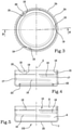
Figure 3 is a bottom view of the cap ofFigure 1 ; -
Figure 4 is a cross-section along the plane IV - IV ofFigure 3 . -
Figure 5 is a cross-section like that ofFigure 4 , showing a cap according to an alternative embodiment; -
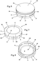
Figure 6 is a perspective view of the cap ofFigure 5 ; -
Figure 7 is a perspective view of a cap according to another alternative embodiment; -
Figure 8 is a perspective view of the cap ofFigure 7 , showing the inner part of the cap; -
Figure 9 is a bottom view of the cap ofFigure 7 ; -
Figure 10 is a cross-section along the plane X - X ofFigure 9 ; -
Figure 11 is a perspective view of a cap according to a further alternative embodiment; -
Figure 12 is a bottom view of the cap ofFigure 11 ; -
Figure 13 is a cross-section along the plane XIII - XIII ofFigure 12 . -
Figures 1 to 4 show acap 1 intended to be applied to a container, for example a bottle, or a jar, or a pot or the like. Thecap 1 is made of a material at least part of which is derived from natural fibres. The part of material derived from natural fibres may be cellulose, which is derived from wood fibres. - The material used to make the
cap 1 may comprise a material derived from natural fibres, to which additives such as dyes, adhesives, lubricants and others have been added if necessary. Alternatively, the material used to make thecap 1 may comprise a material derived from natural fibres, mixed with a natural or synthetic polymeric material. - The
cap 1 comprises a cup-shapedbody 2, inside which acavity 3 is defined. The cup-shapedbody 2 has aninner surface 4, facing thecavity 3 so as to delimit thecavity 3, and anouter surface 5, facing outwards from the cup-shapedbody 2, that is to say facing away from thecavity 3. - The cup-shaped
body 2 comprises askirt 6, which extends around an axis Z. In the example shown, theskirt 6 has a substantially cylindrical shape. - The cup-shaped
body 2 further comprises atransversal wall 7, which extends transversally, in particular perpendicularly, to the axis Z, at one end of theskirt 6. Thetransversal wall 7 may have a circular shape, if seen in plan view. Thetransversal wall 7 may be substantially flat, but this condition is not necessary. - An intended separating
line 10 is provided on theskirt 6 to define anannular band 8 and aclosing element 9. Theclosing element 9 comprises thetransversal wall 7 and alateral wall 11 which extends around the axis Z. Thelateral wall 11 is joined to thetransversal wall 7 in a joiningzone 12. Thelateral wall 11 is a portion of theskirt 6 interposed between thetransversal wall 7 and the intended separatingline 10. - The
annular band 8 is a further portion of theskirt 6 and extends between the intended separatingline 10 and afree edge 13 of theskirt 6. - The intended separating
line 10 may be parallel to thefree edge 13 of theskirt 6. More generally, the intended separatingline 10 may extend in a plane perpendicular to the axis Z. - Before the
cap 1 is applied on the neck of the container, theclosing element 9 is joined to theannular band 8 along the intended separatingline 10. When thecap 1 is opened for the first time, theclosing element 9 separates from theannular band 8 along the intended separatingline 10. Theclosing element 9 may be removed from the container and subsequently re-applied on the related neck, whilst theannular band 8 remains anchored to the neck of the container after opening. - The intended separating
line 10 may comprise a plurality ofbreakable elements 14, which are separated from each other by interruptingsegments 15 at which material is not present. The interruptingsegments 15 may be cut segments obtained by cutting theskirt 6 after the cup-shapedbody 2 has been formed. In this way, abreakable element 14 remains defined between two consecutive cut segments. Alternatively, the interruptingsegments 15 may be obtained while thecap 1 is formed, in the same mould in which thecap 1 is shaped. - The
breakable elements 14 are intended to be broken the first time theclosing element 9 is removed from the container to be brought into an open position. - As shown in
Figures 2 and4 , thelateral wall 11 has at least onefastening element 16 to allow theclosing element 9 to be repeatedly fixed to the container and removed from the latter. - The
fastening element 16 has the shape of a projecting element which from theinner surface 4 projects inwards towards the inside of the cup-shapedbody 2, that is to say, towards thecavity 3. In the example shown, thefastening element 16 is a screw thread suitable for engaging with a corresponding thread made on the neck of the container. - On the
lateral wall 11 there may be a plurality offastening elements 16, as in the example shown, in which there are two screw threads. Alternatively, on thelateral wall 11 there may be asingle fastening element 16, for example a single screw thread having an angular extent greater than the screw threads shown. - On the
outer surface 5 of the cup-shapedbody 2, at thefastening element 16 or at eachfastening element 16, there is a hollow 17, that is to say, a recess which penetrates towards the inside of the cup-shapedbody 2. The hollow 17 has a geometry which copies the geometry of thefastening element 16. In the example shown, in cui which thefastening element 16 is a screw thread, the hollow 17 has a helical shape. - The hollow 17 allows a reduction in the thickness of the
lateral wall 11 at thefastening element 16, compared to the case in which theouter surface 5 were a smooth cylinder, that is to say, the hollow 17 were not present. - In one embodiment, owing to the hollow 17, the thickness of the
lateral wall 11 in the region in which thefastening element 16 is present may be substantially constant. - The number of
hollows 17 is equal to the number offastening elements 16. In the example shown, in which there are twofastening elements 16, thelateral wall 11 has twohollows 17. - The
annular band 8 may comprise at least one engagingelement 18 suitable for engaging with a retaining element provided on the container. The retaining element is intended to keep theannular band 8 anchored to the container, preventing theannular band 8 from being able to be separated from the container when theclosing element 9 is removed. Each engagingelement 18 is shaped like a projecting element which projects inwards towards the inside of the cup-shapedbody 2 from theannular band 8. In the example shown, each engagingelement 18 has an abuttingfront surface 19, which may be substantially flat, suitable for abutting against a stop surface of the retaining element to prevent theannular band 8 from rotating further when theclosing element 9 is unscrewed. The abuttingfront surface 19 may extend in a radial plane, that is to say, in a plane containing the axis Z. - The engaging
element 18 also has a roundedrear end 20. - The engaging
element 18 projects from theinner surface 4 by an amount which gradually decreases from the abuttingfront surface 19 to therear end 20. - The engaging
element 18 may extend along a central line which lies in a plane perpendicular to the axis Z. - However, other geometries of the engaging
element 18 are possible. - In the example shown, as shown in
Figure 3 , there are threeengaging elements 18, but the number ofengaging elements 18 may be selected according to the particular type of container and the characteristics of the cap which must be applied to the container. - On the
outer surface 5 of the cup-shapedbody 2, at the engagingelement 18 or at eachengaging element 18, there is anindentation 21, that is to say, a recess, which penetrates towards the inside of theannular band 8. - The
indentation 21 may have a shape similar to that of the engagingelement 18. Theindentation 21 allows a reduction in the thickness of theannular band 8 at the engagingelement 18 compared to the thickness that theannular band 8 would have if theindentation 21 were not present. Owing to theindentation 21, the thickness of theannular band 8 at the engagingelement 18 may be substantially equal to, or in any case not too dissimilar from, the thickness of theannular band 8 outside of the engagingelement 18. - Made on the
transversal wall 7 there is anannular sealing element 22 which projects from theinner surface 4 towards thecavity 3, that is to say, inwards towards the inside of the cup-shapedbody 2. - The
annular sealing element 22 is suitable for engaging with the container, in particular with an edge region of the neck of the container, so that theclosing element 9 can close the container in a substantially sealed fashion. In the example shown, theannular sealing element 22 is suitable for penetrating inside the neck of the container to make contact with an inner surface of the neck. In an alternative embodiment not shown, theannular sealing element 22 could be sized in such a way as to surround an edge of the neck of the container from the outside, so that it makes contact with an outer surface of the neck, near the rim of the latter. - There may also be more than one annular sealing element on the
transversal wall 7. - In plan view, the
annular sealing element 22, is shaped as a circular protuberance having a centre on the axis Z. - In a plane containing the axis Z, the
annular sealing element 22 may have a cross-section which is "U"-shaped or "V"-shaped with a rounded vertex, with walls which are not necessarily symmetrical. In this way, theannular sealing element 22 may be easily produced in a mould and extracted from the latter, since it is free of undercuts. - On the
outer surface 5 of the cup-shapedbody 2, more precisely on thetransversal wall 7, there is anannular groove 23 which penetrates towards the inside of the cup-shapedbody 2. Theannular groove 23 has the shape of a recess positioned at theannular sealing element 22. - The
annular groove 23 has a geometry corresponding to the shape of theannular sealing element 22. In the example shown, theannular groove 23 is shaped like a circular groove centred on the axis Z. - At the
annular groove 23, the material of thetransversal wall 7 projects inwards towards the inside of the cup-shapedbody 2 thereby defining theannular sealing element 22. - Owing to the
annular groove 23, theannular sealing element 22 is shaped like a corrugation which extends towards thecavity 3. - The
annular groove 23 prevents the creation of a thickening of thetransversal wall 7 at theannular sealing element 22. In this way, it is possible to make the thickness of thetransversal wall 7 more uniform even near theannular groove 23. - That does not mean that the thickness of the
transversal wall 7 must be constant. In contrast, in the example shown, as shown inFigure 4 , in a central region thereof surrounded by theannular sealing element 22, thetransversal wall 7 is thicker than thetransversal wall 7 outside theannular sealing element 22. This makes the central part of thetransversal wall 7 stiffer, reducing the risk that thetransversal wall 7 can swell outwards from the cup-shapedbody 2 or bend inwards towards the inside of the latter. Thecap 1 may also comprise a plurality of grippingribs 24, provided on theouter surface 5 to allow a user to more securely grasp theclosing element 9, reducing the risk that theclosing element 9 will slip whilst the user is handling it. The grippingribs 24 also improve the grip on thecap 1 on a capping machine. - The gripping
ribs 24 may be provided on thelateral wall 11, near the joiningzone 12. The grippingribs 24 may in particular be interposed between thetransversal wall 7 and thehollows 17, so that they do not interfere with thehollows 17. - The gripping
ribs 24 may be shaped like projecting lines which project outwards from theouter surface 5 of the cup-shapedbody 2. In the example shown, the grippingribs 24 project by a limited amount fromouter surface 5. In this case, there are no recesses on theinner surface 4 at thegripping ribs 24. - In an alternative embodiment not shown, on the
inner surface 4 of the cup-shapedbody 2 there may be recesses, in particular shaped like furrows, at thegripping ribs 24, to prevent thelateral wall 11 from having an excessive thickness at thegripping ribs 24. - The gripping
ribs 24 may be straight and extend parallel to the axis Z. - The
cap 1 is formed starting from a material at least part of which is derived from natural fibres, in the dry form (powder or granules), or in the pasty form, or also in the form of a solid film or in the form of a fluff. If the material used to form the cap is in the pasty form, it may be obtained by adding water or another liquid to a dry material. The material at least part of which is derived from natural fibres is introduced into a mould comprising a male mould-part and a female mould-part and compacted between the male part and the female part, which are moved one towards the other. The female part and/or the male part may comprise movable components which are movable to vary the volume of a forming chamber defined between the female part and the male part. - In this way, the cup-shaped
body 2 is obtained, by compression moulding. As already described, theouter surface 5 is shaped in such a way as to substantially copy the three-dimensional profile of theinner surface 4. For that purpose, theouter surface 5 is provided with recesses at the main projecting elements which project from theinner surface 4. The recesses of theouter surface 5 may comprise thehollows 17, and/or theindentations 21 and/or theannular groove 23. That allows the obtainment of the most uniform possible distribution of the density of the material at least part of which is derived from natural fibres in the cup-shapedbody 2. In particular, by avoiding excessive thicknesses of the cup-shapedbody 2 in the positions in which the projecting elements which project from theinner surface 4 are located, it is possible to minimise or eliminate the variations in density between the zones of the cup-shapedbody 2 in which there are projecting elements on theinner surface 4, and the further zones of the cup-shapedbody 2 in which there are no projecting elements on theouter surface 4. Consequently, the properties of thecap 1 are optimised. -
Figures 5 and6 show acap 101 according to an alternative embodiment. Thecap 101 differs from thecap 1 shown inFigures 1 to 4 mainly because it does not comprise theannular sealing element 22. Consequently, thetransversal wall 7 may be free of recesses on itsouter face 25 facing outwards from the cup-shapedbody 2, that is to say, facing the opposite way to thecavity 4. That is to say, there is noannular groove 23. - In this case, the
transversal wall 7 may have a substantially constant thickness. - The
cap 101 may be used to close containers for which a hermetic seal is not essential, for example containers intended to contain substances which are not liquids and/or not foodstuffs. - Alternatively, the
cap 101 may exert a sealing action using additional sealing elements not shown, for example a seal applied on an inner face of thetransversal wall 7. - Whilst
Figures 1 to 6 related to a screw cap,Figures 7 to 9 show a different type ofcap 201, more precisely a so-called "snap-on" cap intended to be applied using pressure on a neck of a container. - The
cap 201 comprises the cup-shapedbody 2 on whoseskirt 6 the intended separatingline 10 is made, the intended separatingline 10 defining theannular band 8 and theclosing element 9, as already described with reference toFigures 1 to 6 . Along the intended separatingline 10 there may be a plurality ofbreakable elements 14, intended to be broken the first time theclosing element 9 is brought into an open position. - However, unlike what happened in
Figures 1 to 6 , the intended separatingline 10 is circumferentially interrupted, so as to leave a connectingportion 26 which connects theclosing element 9 to theannular band 8. Owing to the connectingportion 26, when theclosing element 9 is brought into an open position, theclosing element 9 remains attached to theannular band 8 and cannot be separated from the container to which thecap 201 is applied. - The connecting
portion 26 defines a hinge around which theclosing element 9 can rotate to be brought into the open position. - At the connecting
portion 26, on theskirt 6 there may be a recessed portion ofwall 27 which penetrates towards the inside of the cup-shapedbody 2 fromouter surface 5. The recessed portion ofwall 27 may extend at least from the connectingportion 26 as far as thetransversal wall 7. - The recessed portion of
wall 27 allows the intended separatingline 10 to be made more easily. If the latter is made using a cutting tool, the cutting tool may interact with thecap 201 over an angular extent of 360° around the axis Z. That is to say, there is no need for the cutting tool to operate in a way adjusted to theskirt 6, or interact with theskirt 6 only for a limited angular extent of the latter. The cutting tool does not cut theskirt 6 at the connectingportion 26, since it does not succeed in touching the material of theskirt 6 at the recessed portion ofwall 27, which is closer to the axis Z than the regions of theskirt 6 adjacent to it. - At the recessed portion of
wall 27, thelateral wall 11 of theclosing element 9 projects towards thecavity 3, as shown inFigure 10 . - Provided on the
transversal wall 7 is theannular sealing element 22, which from theinner surface 4 projects inwards towards the inside of the cup-shapedbody 2, that is to say, towards thecavity 3, as was the case in thecap 1. - At the
annular sealing element 22, on thetransversal wall 7 is theannular groove 23, which penetrates in the thickness of thetransversal wall 7 on theouter surface 5, as already described with reference toFigures 1 to 4 . - As well as having a sealing function, the
annular sealing element 22 allows theclosing element 9 to be kept in a closed position, by engaging with the neck of the container, in particular with an inner surface of the neck of the container. That is to say, theclosing element 9 may remain in the closed position owing to the interference which is generated between theannular sealing element 22 and the neck of the container. - It should be noticed that, in the
cap 201, there are no screw threads on thelateral wall 11. - The
closing element 9 has agripping tab 28 which projects outwards from thelateral wall 11. The grippingtab 28 extends transversally, in particular perpendicularly, to the axis Z. The grippingtab 28 may have a flat geometry. The grippingtab 28 is provided in a position diametrically opposite to the connectingportion 26. - The user can act on the gripping
tab 28, in particular on a lower surface of the latter, to more easily bring theclosing element 9 into the open position. The user can also act on the grippingtab 28, in particular on an upper surface of the latter, to return theclosing element 9 to the closed position. Theannular band 8 is provided with a plurality ofengaging elements 218 shaped like projecting elements, which from theinner surface 4 project towards thecavity 3, that is to say, inwards towards the inside of the cup-shapedbody 2. Theengaging elements 218 are intended to engage with at least one retaining element provided on the neck of the container and suitable for preventing theannular band 8 from being able to be removed from the neck. The retaining element may for example comprise an annular enlargement which projects outwards from the neck of the container. Similarly to what was described with reference toFigures 1 to 7 , on theouter surface 5 of the cup-shapedbody 2 there is a plurality ofindentations 221, eachindentation 221 being located at a respectiveengaging element 218. Theindentations 221 have a shape corresponding to the shape of theengaging elements 218. - That allows the thickness of the
annular band 8 at theengaging elements 218 to be kept limited and consequently improves the uniformity of density of thecap 201. - The
engaging elements 218 are functionally similar to theengaging elements 18 described with reference to the caps ofFigures 1 to 6 , from which they differ in shape. In particular, theengaging elements 218 have the shape of circular arcs and extend along respective central lines lying in a plane positioned transversally, in particular perpendicularly, to the axis Z. Each engagingelement 218 may have two rounded ends. The height of eachengaging element 218 measured parallel to the axis Z may be constant at least in a central zone of theengaging element 218. - In one embodiment not shown, on the
inner surface 4 there may be one or more fastening elements which project from theclosing element 9 inwards towards the inside of the cup-shapedbody 2, to more easily keep theclosing element 9 in the closed position. The fastening elements may be shaped like elements projecting towards thecavity 3, not necessarily having the geometry of a screw thread. The fastening elements are intended to engage with corresponding fixing means provided on the neck of the container. On theouter surface 5 of the cup-shapedbody 2, at each fastening element, in this case there is a hollow or recess which penetrates towards the inside of the cup-shapedbody 2, for the reasons previously described with reference toFigures 1 to 6 . -
Figures 11 to 13 show acap 301 according to an alternative embodiment. Thecap 301 is particularly suitable for closing containers which have a wide mouth, such as jars or pots. - Similarly to the
caps Figures 1 to 6 , thecap 301 is a screw cap. However, thecap 301 does not comprise an annular band intended to remain anchored to a container neck. When thecap 301 is brought into an open position, thewhole cap 301 is removed from the neck of the container. - On the
lateral wall 11, thecap 301 is provided with a plurality offastening elements 316 each of which is shaped like a projecting element which from theinner surface 4 projects inwards towards the inside of the cup-shapedbody 2. Eachfastening element 316 has the shape of a portion of screw thread. There is a plurality offastening elements 316, which belong to the same screw thread and are separated by thread-free spaces orgaps 29. The thread-free gaps 29 correspond to smooth portions of theinner surface 4. In the example shown, thecap 301 comprises threefastening elements fastening element 316a. A final portion of screw thread, which during screwing is the last to engage with the corresponding thread of the container, is defined by thefastening element 316c. An intermediate portion of screw thread is defined by thefastening element 316b, interposed between thefastening elements - The
fastening elements 316 present on theinner surface 4 may belong to multiple screw threads. In the example shown, there are three screw threads, distributed around the axis Z at an angular distance of 120* from each other. Each screw thread comprises a plurality of portions of thread (in the example shown, three portions of thread each of which is defined byrespective fastening elements - Fastening
elements 316 belonging to different threads may be aligned along a direction parallel to the axis Z. In the example shown, thefastening element 316a corresponding to an initial portion of thread is aligned, along a direction parallel to the axis Z, with thefastening element 316c corresponding to a final portion of an adjacent thread. In other words, there is at least one plane containing the axis Z which intersects both thefastening element 316a corresponding to an initial portion of thread, and thefastening element 316c corresponding to a final portion of an adjacent thread. - In the thread-
free gaps 29, thefastening elements 316 are not present. - At the
fastening elements 316, on theouter surface 5 of the cup-shapedbody 2, there are recesses orhollows 317, which penetrate towards the inside of thelateral wall 11. Thehollows 317 have a geometry similar to that of thefastening elements 316, that is to say, they are shaped like furrows which extend along a helix positioned around the axis Z. - The
hollows 317 allow a reduction in the thickness of thelateral wall 11 at thefastening elements 316 and therefore compacting of the material which forms thecap 301 with a substantially uniform density, even in the zones in which thefastening elements 316 are present. - On the
outer surface 5 of the cup-shapedbody 2, at the thread-free gaps 29, there are grippingribs 324 which project outwards from thelateral wall 11. Eachgripping rib 324 extends in a direction parallel to the axis Z. - The
gripping ribs 324 allow a user to securely grasp thecap 301 to screw it onto the container and unscrew it from the latter, preventing thecap 301 from slipping in the hands of the user. Moreover, the grippingribs 324 make it easier for thecap 301 to be grasped on a capping machine. - In the example shown, there are groups of three
gripping ribs 324 in each thread-free gap 29, but this feature is not necessary and in each thread-free gap 29 there could be a number ofgripping ribs 324 other than three. - In the regions of the
lateral wall 11 interposed between two consecutive thread-free gaps 29 there are nogripping ribs 324. Otherwise, the grippingribs 324 provided in the regions interposed between two thread-free gaps 29 would interfere with thehollows 317. - On the
inner surface 4 of the cup-shapedbody 2 there are no recesses at thegripping ribs 324 because, in the example shown, the grippingribs 324 project by a limited amount from a cylindrical outer surface of thelateral wall 11. The increase in the thickness of thelateral wall 11 caused by thegripping ribs 324 is limited and does not negatively affect thecap 301. - If the
gripping ribs 324 were to project further from thelateral wall 11, on theinner surface 4 there could be recesses, in particular shaped like furrows, at thegripping ribs 324, so as to prevent excessive increases in the thickness of thelateral wall 11 at thegripping ribs 324 and to favour the most uniform possible compacting of the material of which thecap 301 is made. - The
transversal wall 7 of thecap 301 comprises acentral panel 30 surrounded by acircular projection 31 which projects outwards from thecap 301. In plan view, thecentral panel 30 has a circular shape concentric with the axis Z. Thecircular projection 31 is concentric with thecentral panel 30. On theinner surface 4 of the cup-shapedbody 2, at thecircular projection 31, there is anannular seat 32, shaped like a recess, suitable for receiving a rim of the container to which thecap 301 is intended to be applied. - The
annular seat 32 is delimited by an outerlateral surface 33 and by an innerlateral surface 34 which are facing each other. In the example shown, the innerlateral surface 34 is a surface tilted relative to the axis Z, whilst the outerlateral surface 33 is a cylindrical surface which extends parallel to the axis Z. - The inner
lateral surface 34 and/or the outerlateral surface 33 may engage with the rim of the container, respectively on the inside and on the outside of the latter, to prevent a product contained in the container from coming out. - Interposed between the inner
lateral surface 34 and the outerlateral surface 33 there may be anend surface 35 which extends transversally, in particular perpendicularly, to the axis Z. In the example shown, theend surface 35 is flat. - Since the
annular seat 32 is provided at thecircular projection 31, the thickness of thetransversal wall 7 does not undergo large variations, which allows the density of thecap 301 to be kept substantially uniform. - In the examples shown, gripping elements have been described comprising the gripping
ribs - The gripping elements may project outwards from the skirt, or they may penetrate towards the inside of the skirt. In both cases, the gripping elements create surface irregularities which make it easier to grasp the cap. If the gripping elements project outwards from the skirt, then on the inner surface of the cup-shaped body there may be recesses at the gripping elements. In contrast, if the gripping elements penetrate towards the inside of the skirt from the outer surface of the cup-shaped body, then on the inner surface of the cup-shaped body there may be projecting elements at the gripping elements.
- The caps described above may exert a sealing action, when they engage with the neck of the container, owing to additional sealing elements not shown, for example a seal applied on an inner face of the
transversal wall 7. - The seal may be made of a material at least part of which is derived from natural fibres, for example the same material used to make the cup-shaped
body 2. Alternatively, the seal may be made of a synthetic polymeric material. The seal may have the shape of a round disk, or it may be ringshaped. In general, the seal is made of a material suitable for exerting a sealing action when it engages with the neck of the container. The material of the seal may be a material which is softer than the material used to make the cup-shapedbody 2.
Claims (15)
- A cap for a container, the cap being made of a material at least part of which is derived from natural fibres, the cap comprising a cup-shaped body (2) having a skirt (6) which extends around an axis (Z) and a transversal wall (7) arranged transversally to the axis (Z), a cavity (3) being defined inside the cup-shaped body (2), the cup-shaped body (2) being delimited by an inner surface (4) facing the cavity (3) and by an outer surface (5) facing the opposite way to the cavity (3), wherein at least one projecting element (16, 18, 22; 218; 316) projects from a surface of the cup-shaped body (2) selected from either the inner surface (4) or the outer surface (5), and wherein at least one recess (17, 21, 23; 221; 317) is provided at said at least one projecting element (16, 18, 22; 218; 316) on another surface of the cup-shaped body (2) selected from either the outer surface (5) or the inner surface (4).
- The cap according to claim 1, wherein the surface of the cup-shaped body (2) selected from either the inner surface (4) or the outer surface (5) from which said at least one projecting element (16, 18, 22; 218; 316) projects is the inner surface (4), and wherein said another surface is the outer surface (5).
- The cap according to claim 1 or 2, wherein said at least one projecting element (16, 18, 22; 218; 316) comprises a fastening element (16; 316) which projects from the skirt (6) inwards towards the inside of the cup-shaped body (2) to removably fasten at least one part of the cap to a neck of the container, said at least one recess (17, 21, 23; 221; 317) being provided at the fastening element (16; 316) on the outer surface (5).
- The cap according to claim 3, wherein the fastening element (16; 316) comprises a screw thread, said at least one recess (17, 21, 23; 221; 317) being provided on the outer surface (5) at the screw thread and being shaped like a helical hollow (17; 317).
- The cap according to any preceding claim, and further comprising a plurality of gripping elements (24; 324) made on the skirt (6) to make the cap easier to grasp, the gripping elements (24; 324) being provided in a region of the outer surface (5) in which said at least one recess (17, 21, 23; 221; 317) is not present.
- The cap according to claim 5, as appended to claim 3 or 4, wherein the transversal wall (7) is joined to the skirt (6) in a joining zone (12), the gripping elements (24) being distributed along a region of the skirt (6) interposed between the joining zone (12) and the fastening element (16; 316).
- The cap according to claim 5, as appended to claim 4, wherein the screw thread comprises a plurality of portions of thread separated by thread-free gaps (29) on the inner surface (4) of the cup-shaped body (2) and wherein the gripping elements (324) are provided on the outer surface (5) in zones arranged at the thread-free gaps (29)
- The cap according to any one of claims 5 to 7, wherein each gripping element (24; 124) is shaped like a projection or alternatively a recess provided on the outer surface (5), on the inner surface (4) a recess or respectively a projection being provided at the gripping element (24; 324).
- The cap according to any preceding claim, wherein said at least one projecting element (16, 18, 22; 218; 316) comprises an annular sealing element (22), which from the transversal wall (7) projects inwards towards the inside of the cup-shaped body (2) to sealingly engage with an edge region of a neck of the container, said at least one recess (17, 21, 23; 221; 317) being an annular groove (23) provided on the outer surface (4) at the annular sealing element (22), and wherein optionally the annular sealing element (22) has, in a plane containing said axis (Z) a cross-section which is "U"-shaped or "V"-shaped with a rounded vertex.
- The cap according to any preceding claim, wherein an intended separating line (10) is provided on the skirt (6), the intended separating line (10) extending around the axis (Z) and defining on the cup-shaped body (2) a closing element (9) and an annular band (8), said at least one projecting element (16, 18, 22; 218; 316) comprising an engaging element (18; 218) which projects from the annular band (8) to engage with a retaining element provided on a neck of the container and to prevent the annular band (8) from being removed from the neck, said at least one recess (17, 21, 23; 221; 317) being provided at the engaging element (18; 218), and wherein optionally the engaging element (18; 218) extends along a central line which lies in a plane perpendicular to the axis (Z).
- The cap according to claim 10, wherein the intended separating line (11) is circumferentially interrupted around the axis (Z) so as to define a connecting portion (26) along which the closing element (9) remains joined to the annular band (8) after having been brought into an open position.
- The cap according to any preceding claim, wherein the part of material derived from natural fibres is cellulose.
- The cap according to any preceding claim, wherein the transversal wall (7) has an inner face, a seal being anchored to the inner face to engage with a neck of the container, the seal being made of a material which is softer than the material of the cup-shaped body (2), and wherein optionally the seal is made of a material at least part of which is derived from natural fibres, for example the same material used to make the cup-shaped body (2).
- A method for producing a cap, the cap comprising a cup-shaped body (2) inside which a cavity (3) is defined, the cup-shaped body (2) being delimited by an inner surface (4) facing towards the cavity (3) and by an outer surface (5) facing the opposite way to the cavity (3), wherein the cap is produced during a step of pressing a material at least part of which is derived from natural fibres, the step of pressing comprising forming at least one projecting element (16, 18, 22; 218; 316) on a surface of the cup-shaped body (2) selected from either the inner surface (4) or the outer surface (5), and forming at least one recess (17, 21, 23; 221; 317) on another surface of the cup-shaped body (2) selected from either the outer surface (5) or the inner surface (4) at said at least one projecting element (16, 18, 22; 218; 316), thereby minimising the differences in compaction between distinct zones of the cup-shaped body (2).
- The method according to claim 14, wherein the part of material derived from natural fibres comprises cellulose.
Applications Claiming Priority (1)
| Application Number | Priority Date | Filing Date | Title |
|---|---|---|---|
| IT202000019534 | 2020-08-06 |
Publications (2)
| Publication Number | Publication Date |
|---|---|
| EP3950527A1 true EP3950527A1 (en) | 2022-02-09 |
| EP3950527B1 EP3950527B1 (en) | 2022-11-30 |
Family
ID=72886056
Family Applications (1)
| Application Number | Title | Priority Date | Filing Date |
|---|---|---|---|
| EP21189466.2A Active EP3950527B1 (en) | 2020-08-06 | 2021-08-03 | Cap for a container and related production method |
Country Status (7)
| Country | Link |
|---|---|
| US (1) | US12116176B2 (en) |
| EP (1) | EP3950527B1 (en) |
| CN (1) | CN114056744B (en) |
| BR (1) | BR102021015390A2 (en) |
| ES (1) | ES2935697T3 (en) |
| MX (1) | MX2021009455A (en) |
| ZA (1) | ZA202105555B (en) |
Cited By (2)
| Publication number | Priority date | Publication date | Assignee | Title |
|---|---|---|---|---|
| IT202200005330A1 (en) * | 2022-03-18 | 2023-09-18 | Sacmi | Cap for a container and relative manufacturing method. |
| SE2350453A1 (en) * | 2023-04-17 | 2024-10-18 | Blue Ocean Closures Ab | Press molding method including a collapsible stamp member for producing a cup shaped fiber product |
Families Citing this family (9)
| Publication number | Priority date | Publication date | Assignee | Title |
|---|---|---|---|---|
| USD1027646S1 (en) * | 2021-01-13 | 2024-05-21 | Deltona Innovations Ag | Closure cap for container |
| IT202200006653A1 (en) * | 2022-04-04 | 2023-10-04 | Sacmi | Caps for a container and method of producing a cap for a container. |
| FR3137898A1 (en) * | 2022-07-12 | 2024-01-19 | Bernard DERRIEN | caps, lids and screwed ends made from plant fibers |
| CH720096B1 (en) * | 2022-10-06 | 2025-07-31 | Alpla Werke Alwin Lehner Gmbh & Co Kg | Device for coating fiber-based hollow bodies. |
| USD1082447S1 (en) | 2022-11-18 | 2025-07-08 | Reynolds Presto Products Inc. | Container with lid |
| USD1094026S1 (en) | 2022-11-18 | 2025-09-23 | Reynolds Presto Products Inc. | Container with lid |
| USD1035446S1 (en) | 2022-11-18 | 2024-07-16 | Reynolds Presto Products Inc. | Container with lid |
| NO348224B1 (en) * | 2022-12-22 | 2024-10-07 | Elopak Asa | Cellulose based fiber material closure device for a paper or paperboard-based package |
| DE102023105573A1 (en) * | 2023-03-07 | 2024-09-12 | Krones Aktiengesellschaft | A container comprising fibres comprising a container body comprising fibres and a fibre-comprising hinged closure arranged on the container body, and fibre-comprising hinged closure |
Citations (4)
| Publication number | Priority date | Publication date | Assignee | Title |
|---|---|---|---|---|
| US2398553A (en) * | 1942-05-09 | 1946-04-16 | F N Burt Company Inc | Closure |
| GB607700A (en) * | 1942-11-11 | 1948-09-03 | American Seal Kap Corp | Improvements in or relating to paper screw caps |
| US8701905B2 (en) * | 2008-12-19 | 2014-04-22 | Double Double D, Llc | Environmentally friendly liquid container and method of manufacture |
| US9452863B2 (en) * | 2008-10-01 | 2016-09-27 | Greater Good, Inc. | Biodegradable container for liquid and/or semi-solid products |
Family Cites Families (34)
| Publication number | Priority date | Publication date | Assignee | Title |
|---|---|---|---|---|
| US1548459A (en) * | 1923-12-14 | 1925-08-04 | Hammer Charles | Metal cap |
| US2104236A (en) * | 1936-04-06 | 1938-01-04 | Irving L Mermer | Indicating closure for bottles |
| US2168321A (en) * | 1936-11-12 | 1939-08-08 | Cherry Burrell Corp | Receptacle and closure cap therefor |
| US2214255A (en) * | 1937-07-27 | 1940-09-10 | Cherry Burrell Corp | Receptacle and closure cap therefor |
| US2134178A (en) * | 1937-08-24 | 1938-10-25 | August E Esposito | Bottle cap |
| US2382873A (en) * | 1942-11-11 | 1945-08-14 | American Seal Kap Corp | Paper screw cap |
| US2423582A (en) * | 1945-02-27 | 1947-07-08 | Robert Troxel | Bottle cap |
| US3235115A (en) * | 1960-09-30 | 1966-02-15 | Aluminum Co Of America | Tamperproof closures |
| US3233814A (en) * | 1963-01-24 | 1966-02-08 | Continental Can Co | Fiber cover for fiber drums |
| US3314564A (en) * | 1965-05-06 | 1967-04-18 | West Co | Container closure |
| US3489307A (en) * | 1968-06-10 | 1970-01-13 | Haskon Inc | Screw-type cap having fulcrum seal |
| US3606063A (en) * | 1969-05-22 | 1971-09-20 | Klm Co | Threaded plastic closure |
| US3743128A (en) * | 1969-05-22 | 1973-07-03 | Klm Co | Closure and closure die |
| BE758777A (en) * | 1969-11-11 | 1971-04-16 | Seidel Kg Geb | METAL CLOSING CAP AND RECEPTACLE INTENDED TO BE CLOSED BECAUSE CAP |
| US3773205A (en) * | 1971-03-04 | 1973-11-20 | Klm Co Stratford | Thermoformed closures which are sealed to containers by the use of sonic energy and the method of sealing the same |
| US3788509A (en) * | 1972-01-28 | 1974-01-29 | Klm Co | Method and apparatus for sealing plastic closures to plastic containers |
| US3904061A (en) * | 1973-05-14 | 1975-09-09 | Klm Company | Tamper-proof bottle closure |
| US4361457A (en) * | 1973-05-18 | 1982-11-30 | The Klm Company | Method for making a container closure with liner |
| US4153174A (en) * | 1975-11-17 | 1979-05-08 | The Klm Company | Tamper-proof closure |
| US4209101A (en) * | 1977-09-14 | 1980-06-24 | Sweetheart Plastic, Inc. | Tamper-proof closure and method of making same |
| US4225050A (en) * | 1979-05-21 | 1980-09-30 | Segen Industries, Inc. | Tamper-proof bottle caps and method of forming same |
| US4337870A (en) * | 1980-04-23 | 1982-07-06 | Keeler Frederick D | Tamper-proof closure cap and method of fabrication |
| US4423820A (en) * | 1982-03-01 | 1984-01-03 | Klm Company | Tamper proof closure and method of manufacturing same |
| US4700860A (en) * | 1986-03-31 | 1987-10-20 | Owens-Illinois, Inc. | Tamper indicating vacuum package |
| US5320233A (en) * | 1993-08-30 | 1994-06-14 | Aluminum Company Of America | Tamper evident lug cap |
| JP2004036044A (en) * | 2002-07-03 | 2004-02-05 | Kao Corp | Method for producing fiber molded body |
| JP3970173B2 (en) * | 2002-12-02 | 2007-09-05 | 花王株式会社 | Method for producing pulp molded article |
| WO2009132318A1 (en) * | 2008-04-25 | 2009-10-29 | Seanet Development, Inc. | Molded, recyclable, compostable cellulose fiber lid assembly for a container |
| WO2015157877A1 (en) * | 2014-04-15 | 2015-10-22 | 赖宗伸 | Manufacturing method for outer covering edge of molded cup lid and product |
| TWM491639U (en) * | 2014-08-01 | 2014-12-11 | Eco Material Corp Ltd | Lid structure for environmental protection paper cup |
| TWI610007B (en) * | 2016-09-23 | 2018-01-01 | Paper plastic cover body and forming device thereof | |
| CN208248868U (en) * | 2018-02-26 | 2018-12-18 | 国际竹藤中心 | A kind of anti-leakage cover of bamboo fiber molded tableware cup |
| CN110641825A (en) * | 2019-10-29 | 2020-01-03 | 浙江欧亚轻工装备制造有限公司 | Plant fiber molding cup cover with inner convex ring and manufacturing method |
| AU2020100089A4 (en) * | 2020-01-16 | 2020-03-05 | Bio Meraki Pty Ltd | Paper pulp cup lids with double lock structure and its forming method |
-
2021
- 2021-07-30 US US17/390,306 patent/US12116176B2/en active Active
- 2021-08-03 EP EP21189466.2A patent/EP3950527B1/en active Active
- 2021-08-03 ES ES21189466T patent/ES2935697T3/en active Active
- 2021-08-04 BR BR102021015390-3A patent/BR102021015390A2/en unknown
- 2021-08-05 MX MX2021009455A patent/MX2021009455A/en unknown
- 2021-08-05 CN CN202110898691.1A patent/CN114056744B/en active Active
- 2021-08-06 ZA ZA2021/05555A patent/ZA202105555B/en unknown
Patent Citations (4)
| Publication number | Priority date | Publication date | Assignee | Title |
|---|---|---|---|---|
| US2398553A (en) * | 1942-05-09 | 1946-04-16 | F N Burt Company Inc | Closure |
| GB607700A (en) * | 1942-11-11 | 1948-09-03 | American Seal Kap Corp | Improvements in or relating to paper screw caps |
| US9452863B2 (en) * | 2008-10-01 | 2016-09-27 | Greater Good, Inc. | Biodegradable container for liquid and/or semi-solid products |
| US8701905B2 (en) * | 2008-12-19 | 2014-04-22 | Double Double D, Llc | Environmentally friendly liquid container and method of manufacture |
Cited By (3)
| Publication number | Priority date | Publication date | Assignee | Title |
|---|---|---|---|---|
| IT202200005330A1 (en) * | 2022-03-18 | 2023-09-18 | Sacmi | Cap for a container and relative manufacturing method. |
| SE2350453A1 (en) * | 2023-04-17 | 2024-10-18 | Blue Ocean Closures Ab | Press molding method including a collapsible stamp member for producing a cup shaped fiber product |
| SE547108C2 (en) * | 2023-04-17 | 2025-04-22 | Blue Ocean Closures Ab | Press molding method including a collapsible stamp member for producing a cup shaped fiber product |
Also Published As
| Publication number | Publication date |
|---|---|
| US20220041340A1 (en) | 2022-02-10 |
| CN114056744A (en) | 2022-02-18 |
| CN114056744B (en) | 2025-09-23 |
| BR102021015390A2 (en) | 2022-02-22 |
| EP3950527B1 (en) | 2022-11-30 |
| ES2935697T3 (en) | 2023-03-09 |
| MX2021009455A (en) | 2022-02-07 |
| ZA202105555B (en) | 2022-09-28 |
| US12116176B2 (en) | 2024-10-15 |
Similar Documents
| Publication | Publication Date | Title |
|---|---|---|
| EP3950527B1 (en) | Cap for a container and related production method | |
| US11338970B2 (en) | Closure assembly | |
| CN100436275C (en) | Closure assembly for wide-mouth container | |
| AU738312B2 (en) | Plastic lug closure | |
| US8071004B2 (en) | Closure having band with internal thread formed by impression | |
| CA2281705C (en) | Plastic screw top | |
| CA2521090C (en) | Closure with enhanced removal capability | |
| US4984701A (en) | Tamper-evident closure | |
| US4635808A (en) | Plastic cap | |
| EP4001155B1 (en) | Container cap and container combined with same | |
| KR20150016975A (en) | Closure with application guide | |
| US6102227A (en) | Snap-on cap with twist on/off reclosure lid | |
| US4903849A (en) | Tamper evident cap and bottle | |
| US11021303B2 (en) | Container closure with ribs formed in sealing compound | |
| US3606063A (en) | Threaded plastic closure | |
| RU2825034C2 (en) | Cover for container and method of making such cover | |
| WO2001085563A1 (en) | Plastic cap with gasket | |
| CA2536867C (en) | Composite closure having an insert with a peripheral curl | |
| RU2860024C2 (en) | Neck for containers and closing device for containers | |
| CA3031865C (en) | Container closure with ribs formed in sealing compound | |
| MXPA99007465A (en) | Plastic screw top | |
| JPS60148463A (en) | Vessel cover made of synthetic resin having pilfer-proof characteristic |
Legal Events
| Date | Code | Title | Description |
|---|---|---|---|
| PUAI | Public reference made under article 153(3) epc to a published international application that has entered the european phase |
Free format text: ORIGINAL CODE: 0009012 |
|
| STAA | Information on the status of an ep patent application or granted ep patent |
Free format text: STATUS: THE APPLICATION HAS BEEN PUBLISHED |
|
| AK | Designated contracting states |
Kind code of ref document: A1 Designated state(s): AL AT BE BG CH CY CZ DE DK EE ES FI FR GB GR HR HU IE IS IT LI LT LU LV MC MK MT NL NO PL PT RO RS SE SI SK SM TR |
|
| STAA | Information on the status of an ep patent application or granted ep patent |
Free format text: STATUS: REQUEST FOR EXAMINATION WAS MADE |
|
| 17P | Request for examination filed |
Effective date: 20220427 |
|
| RBV | Designated contracting states (corrected) |
Designated state(s): AL AT BE BG CH CY CZ DE DK EE ES FI FR GB GR HR HU IE IS IT LI LT LU LV MC MK MT NL NO PL PT RO RS SE SI SK SM TR |
|
| GRAP | Despatch of communication of intention to grant a patent |
Free format text: ORIGINAL CODE: EPIDOSNIGR1 |
|
| STAA | Information on the status of an ep patent application or granted ep patent |
Free format text: STATUS: GRANT OF PATENT IS INTENDED |
|
| INTG | Intention to grant announced |
Effective date: 20220914 |
|
| GRAS | Grant fee paid |
Free format text: ORIGINAL CODE: EPIDOSNIGR3 |
|
| GRAA | (expected) grant |
Free format text: ORIGINAL CODE: 0009210 |
|
| STAA | Information on the status of an ep patent application or granted ep patent |
Free format text: STATUS: THE PATENT HAS BEEN GRANTED |
|
| AK | Designated contracting states |
Kind code of ref document: B1 Designated state(s): AL AT BE BG CH CY CZ DE DK EE ES FI FR GB GR HR HU IE IS IT LI LT LU LV MC MK MT NL NO PL PT RO RS SE SI SK SM TR |
|
| REG | Reference to a national code |
Ref country code: CH Ref legal event code: EP Ref country code: GB Ref legal event code: FG4D |
|
| REG | Reference to a national code |
Ref country code: AT Ref legal event code: REF Ref document number: 1534525 Country of ref document: AT Kind code of ref document: T Effective date: 20221215 |
|
| REG | Reference to a national code |
Ref country code: IE Ref legal event code: FG4D |
|
| REG | Reference to a national code |
Ref country code: DE Ref legal event code: R096 Ref document number: 602021000879 Country of ref document: DE |
|
| REG | Reference to a national code |
Ref country code: SE Ref legal event code: TRGR |
|
| REG | Reference to a national code |
Ref country code: ES Ref legal event code: FG2A Ref document number: 2935697 Country of ref document: ES Kind code of ref document: T3 Effective date: 20230309 |
|
| REG | Reference to a national code |
Ref country code: LT Ref legal event code: MG9D |
|
| REG | Reference to a national code |
Ref country code: NL Ref legal event code: MP Effective date: 20221130 |
|
| PG25 | Lapsed in a contracting state [announced via postgrant information from national office to epo] |
Ref country code: PT Free format text: LAPSE BECAUSE OF FAILURE TO SUBMIT A TRANSLATION OF THE DESCRIPTION OR TO PAY THE FEE WITHIN THE PRESCRIBED TIME-LIMIT Effective date: 20230331 Ref country code: NO Free format text: LAPSE BECAUSE OF FAILURE TO SUBMIT A TRANSLATION OF THE DESCRIPTION OR TO PAY THE FEE WITHIN THE PRESCRIBED TIME-LIMIT Effective date: 20230228 Ref country code: LT Free format text: LAPSE BECAUSE OF FAILURE TO SUBMIT A TRANSLATION OF THE DESCRIPTION OR TO PAY THE FEE WITHIN THE PRESCRIBED TIME-LIMIT Effective date: 20221130 Ref country code: FI Free format text: LAPSE BECAUSE OF FAILURE TO SUBMIT A TRANSLATION OF THE DESCRIPTION OR TO PAY THE FEE WITHIN THE PRESCRIBED TIME-LIMIT Effective date: 20221130 |
|
| PG25 | Lapsed in a contracting state [announced via postgrant information from national office to epo] |
Ref country code: RS Free format text: LAPSE BECAUSE OF FAILURE TO SUBMIT A TRANSLATION OF THE DESCRIPTION OR TO PAY THE FEE WITHIN THE PRESCRIBED TIME-LIMIT Effective date: 20221130 Ref country code: PL Free format text: LAPSE BECAUSE OF FAILURE TO SUBMIT A TRANSLATION OF THE DESCRIPTION OR TO PAY THE FEE WITHIN THE PRESCRIBED TIME-LIMIT Effective date: 20221130 Ref country code: LV Free format text: LAPSE BECAUSE OF FAILURE TO SUBMIT A TRANSLATION OF THE DESCRIPTION OR TO PAY THE FEE WITHIN THE PRESCRIBED TIME-LIMIT Effective date: 20221130 Ref country code: IS Free format text: LAPSE BECAUSE OF FAILURE TO SUBMIT A TRANSLATION OF THE DESCRIPTION OR TO PAY THE FEE WITHIN THE PRESCRIBED TIME-LIMIT Effective date: 20230330 Ref country code: HR Free format text: LAPSE BECAUSE OF FAILURE TO SUBMIT A TRANSLATION OF THE DESCRIPTION OR TO PAY THE FEE WITHIN THE PRESCRIBED TIME-LIMIT Effective date: 20221130 Ref country code: GR Free format text: LAPSE BECAUSE OF FAILURE TO SUBMIT A TRANSLATION OF THE DESCRIPTION OR TO PAY THE FEE WITHIN THE PRESCRIBED TIME-LIMIT Effective date: 20230301 |
|
| PG25 | Lapsed in a contracting state [announced via postgrant information from national office to epo] |
Ref country code: NL Free format text: LAPSE BECAUSE OF FAILURE TO SUBMIT A TRANSLATION OF THE DESCRIPTION OR TO PAY THE FEE WITHIN THE PRESCRIBED TIME-LIMIT Effective date: 20221130 |
|
| P01 | Opt-out of the competence of the unified patent court (upc) registered |
Effective date: 20230525 |
|
| PG25 | Lapsed in a contracting state [announced via postgrant information from national office to epo] |
Ref country code: SM Free format text: LAPSE BECAUSE OF FAILURE TO SUBMIT A TRANSLATION OF THE DESCRIPTION OR TO PAY THE FEE WITHIN THE PRESCRIBED TIME-LIMIT Effective date: 20221130 Ref country code: RO Free format text: LAPSE BECAUSE OF FAILURE TO SUBMIT A TRANSLATION OF THE DESCRIPTION OR TO PAY THE FEE WITHIN THE PRESCRIBED TIME-LIMIT Effective date: 20221130 Ref country code: EE Free format text: LAPSE BECAUSE OF FAILURE TO SUBMIT A TRANSLATION OF THE DESCRIPTION OR TO PAY THE FEE WITHIN THE PRESCRIBED TIME-LIMIT Effective date: 20221130 Ref country code: DK Free format text: LAPSE BECAUSE OF FAILURE TO SUBMIT A TRANSLATION OF THE DESCRIPTION OR TO PAY THE FEE WITHIN THE PRESCRIBED TIME-LIMIT Effective date: 20221130 Ref country code: CZ Free format text: LAPSE BECAUSE OF FAILURE TO SUBMIT A TRANSLATION OF THE DESCRIPTION OR TO PAY THE FEE WITHIN THE PRESCRIBED TIME-LIMIT Effective date: 20221130 |
|
| PG25 | Lapsed in a contracting state [announced via postgrant information from national office to epo] |
Ref country code: SK Free format text: LAPSE BECAUSE OF FAILURE TO SUBMIT A TRANSLATION OF THE DESCRIPTION OR TO PAY THE FEE WITHIN THE PRESCRIBED TIME-LIMIT Effective date: 20221130 Ref country code: AL Free format text: LAPSE BECAUSE OF FAILURE TO SUBMIT A TRANSLATION OF THE DESCRIPTION OR TO PAY THE FEE WITHIN THE PRESCRIBED TIME-LIMIT Effective date: 20221130 |
|
| REG | Reference to a national code |
Ref country code: DE Ref legal event code: R097 Ref document number: 602021000879 Country of ref document: DE |
|
| PLBE | No opposition filed within time limit |
Free format text: ORIGINAL CODE: 0009261 |
|
| STAA | Information on the status of an ep patent application or granted ep patent |
Free format text: STATUS: NO OPPOSITION FILED WITHIN TIME LIMIT |
|
| 26N | No opposition filed |
Effective date: 20230831 |
|
| PG25 | Lapsed in a contracting state [announced via postgrant information from national office to epo] |
Ref country code: SI Free format text: LAPSE BECAUSE OF FAILURE TO SUBMIT A TRANSLATION OF THE DESCRIPTION OR TO PAY THE FEE WITHIN THE PRESCRIBED TIME-LIMIT Effective date: 20221130 |
|
| REG | Reference to a national code |
Ref country code: AT Ref legal event code: UEP Ref document number: 1534525 Country of ref document: AT Kind code of ref document: T Effective date: 20221130 |
|
| PG25 | Lapsed in a contracting state [announced via postgrant information from national office to epo] |
Ref country code: MC Free format text: LAPSE BECAUSE OF FAILURE TO SUBMIT A TRANSLATION OF THE DESCRIPTION OR TO PAY THE FEE WITHIN THE PRESCRIBED TIME-LIMIT Effective date: 20221130 |
|
| PG25 | Lapsed in a contracting state [announced via postgrant information from national office to epo] |
Ref country code: MC Free format text: LAPSE BECAUSE OF FAILURE TO SUBMIT A TRANSLATION OF THE DESCRIPTION OR TO PAY THE FEE WITHIN THE PRESCRIBED TIME-LIMIT Effective date: 20221130 |
|
| PG25 | Lapsed in a contracting state [announced via postgrant information from national office to epo] |
Ref country code: LU Free format text: LAPSE BECAUSE OF NON-PAYMENT OF DUE FEES Effective date: 20230803 |
|
| PG25 | Lapsed in a contracting state [announced via postgrant information from national office to epo] |
Ref country code: LU Free format text: LAPSE BECAUSE OF NON-PAYMENT OF DUE FEES Effective date: 20230803 |
|
| REG | Reference to a national code |
Ref country code: BE Ref legal event code: MM Effective date: 20230831 |
|
| REG | Reference to a national code |
Ref country code: IE Ref legal event code: MM4A |
|
| PG25 | Lapsed in a contracting state [announced via postgrant information from national office to epo] |
Ref country code: IE Free format text: LAPSE BECAUSE OF NON-PAYMENT OF DUE FEES Effective date: 20230803 |
|
| PG25 | Lapsed in a contracting state [announced via postgrant information from national office to epo] |
Ref country code: IE Free format text: LAPSE BECAUSE OF NON-PAYMENT OF DUE FEES Effective date: 20230803 |
|
| PG25 | Lapsed in a contracting state [announced via postgrant information from national office to epo] |
Ref country code: BE Free format text: LAPSE BECAUSE OF NON-PAYMENT OF DUE FEES Effective date: 20230831 |
|
| PG25 | Lapsed in a contracting state [announced via postgrant information from national office to epo] |
Ref country code: BG Free format text: LAPSE BECAUSE OF FAILURE TO SUBMIT A TRANSLATION OF THE DESCRIPTION OR TO PAY THE FEE WITHIN THE PRESCRIBED TIME-LIMIT Effective date: 20221130 |
|
| PG25 | Lapsed in a contracting state [announced via postgrant information from national office to epo] |
Ref country code: BG Free format text: LAPSE BECAUSE OF FAILURE TO SUBMIT A TRANSLATION OF THE DESCRIPTION OR TO PAY THE FEE WITHIN THE PRESCRIBED TIME-LIMIT Effective date: 20221130 |
|
| PG25 | Lapsed in a contracting state [announced via postgrant information from national office to epo] |
Ref country code: CY Free format text: LAPSE BECAUSE OF FAILURE TO SUBMIT A TRANSLATION OF THE DESCRIPTION OR TO PAY THE FEE WITHIN THE PRESCRIBED TIME-LIMIT; INVALID AB INITIO Effective date: 20210803 |
|
| PG25 | Lapsed in a contracting state [announced via postgrant information from national office to epo] |
Ref country code: HU Free format text: LAPSE BECAUSE OF FAILURE TO SUBMIT A TRANSLATION OF THE DESCRIPTION OR TO PAY THE FEE WITHIN THE PRESCRIBED TIME-LIMIT; INVALID AB INITIO Effective date: 20210803 |
|
| PGFP | Annual fee paid to national office [announced via postgrant information from national office to epo] |
Ref country code: ES Payment date: 20250901 Year of fee payment: 5 |
|
| PGFP | Annual fee paid to national office [announced via postgrant information from national office to epo] |
Ref country code: DE Payment date: 20250724 Year of fee payment: 5 |
|
| PGFP | Annual fee paid to national office [announced via postgrant information from national office to epo] |
Ref country code: TR Payment date: 20250729 Year of fee payment: 5 Ref country code: IT Payment date: 20250806 Year of fee payment: 5 |
|
| PGFP | Annual fee paid to national office [announced via postgrant information from national office to epo] |
Ref country code: GB Payment date: 20250826 Year of fee payment: 5 |
|
| PGFP | Annual fee paid to national office [announced via postgrant information from national office to epo] |
Ref country code: AT Payment date: 20251020 Year of fee payment: 5 Ref country code: FR Payment date: 20250725 Year of fee payment: 5 |
|
| PGFP | Annual fee paid to national office [announced via postgrant information from national office to epo] |
Ref country code: CH Payment date: 20250901 Year of fee payment: 5 Ref country code: SE Payment date: 20250723 Year of fee payment: 5 |