EP3950526A1 - Pouch, lidded container, and tube - Google Patents
Pouch, lidded container, and tube Download PDFInfo
- Publication number
- EP3950526A1 EP3950526A1 EP20782813.8A EP20782813A EP3950526A1 EP 3950526 A1 EP3950526 A1 EP 3950526A1 EP 20782813 A EP20782813 A EP 20782813A EP 3950526 A1 EP3950526 A1 EP 3950526A1
- Authority
- EP
- European Patent Office
- Prior art keywords
- packaging material
- pouch
- hole
- region
- line
- Prior art date
- Legal status (The legal status is an assumption and is not a legal conclusion. Google has not performed a legal analysis and makes no representation as to the accuracy of the status listed.)
- Withdrawn
Links
Images


Classifications
-
- B—PERFORMING OPERATIONS; TRANSPORTING
- B65—CONVEYING; PACKING; STORING; HANDLING THIN OR FILAMENTARY MATERIAL
- B65D—CONTAINERS FOR STORAGE OR TRANSPORT OF ARTICLES OR MATERIALS, e.g. BAGS, BARRELS, BOTTLES, BOXES, CANS, CARTONS, CRATES, DRUMS, JARS, TANKS, HOPPERS, FORWARDING CONTAINERS; ACCESSORIES, CLOSURES, OR FITTINGS THEREFOR; PACKAGING ELEMENTS; PACKAGES
- B65D25/00—Details of other kinds or types of rigid or semi-rigid containers
- B65D25/20—External fittings
- B65D25/22—External fittings for facilitating lifting or suspending of containers
-
- B—PERFORMING OPERATIONS; TRANSPORTING
- B65—CONVEYING; PACKING; STORING; HANDLING THIN OR FILAMENTARY MATERIAL
- B65D—CONTAINERS FOR STORAGE OR TRANSPORT OF ARTICLES OR MATERIALS, e.g. BAGS, BARRELS, BOTTLES, BOXES, CANS, CARTONS, CRATES, DRUMS, JARS, TANKS, HOPPERS, FORWARDING CONTAINERS; ACCESSORIES, CLOSURES, OR FITTINGS THEREFOR; PACKAGING ELEMENTS; PACKAGES
- B65D33/00—Details of, or accessories for, sacks or bags
- B65D33/02—Local reinforcements or stiffening inserts, e.g. wires, strings, strips or frames
-
- B—PERFORMING OPERATIONS; TRANSPORTING
- B65—CONVEYING; PACKING; STORING; HANDLING THIN OR FILAMENTARY MATERIAL
- B65D—CONTAINERS FOR STORAGE OR TRANSPORT OF ARTICLES OR MATERIALS, e.g. BAGS, BARRELS, BOTTLES, BOXES, CANS, CARTONS, CRATES, DRUMS, JARS, TANKS, HOPPERS, FORWARDING CONTAINERS; ACCESSORIES, CLOSURES, OR FITTINGS THEREFOR; PACKAGING ELEMENTS; PACKAGES
- B65D33/00—Details of, or accessories for, sacks or bags
- B65D33/14—Suspension means
-
- B—PERFORMING OPERATIONS; TRANSPORTING
- B65—CONVEYING; PACKING; STORING; HANDLING THIN OR FILAMENTARY MATERIAL
- B65D—CONTAINERS FOR STORAGE OR TRANSPORT OF ARTICLES OR MATERIALS, e.g. BAGS, BARRELS, BOTTLES, BOXES, CANS, CARTONS, CRATES, DRUMS, JARS, TANKS, HOPPERS, FORWARDING CONTAINERS; ACCESSORIES, CLOSURES, OR FITTINGS THEREFOR; PACKAGING ELEMENTS; PACKAGES
- B65D35/00—Pliable tubular containers adapted to be permanently or temporarily deformed to expel contents, e.g. collapsible tubes for toothpaste or other plastic or semi-liquid material; Holders therefor
- B65D35/24—Pliable tubular containers adapted to be permanently or temporarily deformed to expel contents, e.g. collapsible tubes for toothpaste or other plastic or semi-liquid material; Holders therefor with auxiliary devices
-
- B—PERFORMING OPERATIONS; TRANSPORTING
- B65—CONVEYING; PACKING; STORING; HANDLING THIN OR FILAMENTARY MATERIAL
- B65D—CONTAINERS FOR STORAGE OR TRANSPORT OF ARTICLES OR MATERIALS, e.g. BAGS, BARRELS, BOTTLES, BOXES, CANS, CARTONS, CRATES, DRUMS, JARS, TANKS, HOPPERS, FORWARDING CONTAINERS; ACCESSORIES, CLOSURES, OR FITTINGS THEREFOR; PACKAGING ELEMENTS; PACKAGES
- B65D75/00—Packages comprising articles or materials partially or wholly enclosed in strips, sheets, blanks, tubes, or webs of flexible sheet material, e.g. in folded wrappers
- B65D75/008—Standing pouches, i.e. "Standbeutel"
-
- B—PERFORMING OPERATIONS; TRANSPORTING
- B65—CONVEYING; PACKING; STORING; HANDLING THIN OR FILAMENTARY MATERIAL
- B65D—CONTAINERS FOR STORAGE OR TRANSPORT OF ARTICLES OR MATERIALS, e.g. BAGS, BARRELS, BOTTLES, BOXES, CANS, CARTONS, CRATES, DRUMS, JARS, TANKS, HOPPERS, FORWARDING CONTAINERS; ACCESSORIES, CLOSURES, OR FITTINGS THEREFOR; PACKAGING ELEMENTS; PACKAGES
- B65D75/00—Packages comprising articles or materials partially or wholly enclosed in strips, sheets, blanks, tubes, or webs of flexible sheet material, e.g. in folded wrappers
- B65D75/52—Details
- B65D75/54—Cards, coupons, or other inserts or accessories
- B65D75/56—Handles or other suspension means
- B65D75/566—Hand holes or suspension apertures
-
- B—PERFORMING OPERATIONS; TRANSPORTING
- B65—CONVEYING; PACKING; STORING; HANDLING THIN OR FILAMENTARY MATERIAL
- B65D—CONTAINERS FOR STORAGE OR TRANSPORT OF ARTICLES OR MATERIALS, e.g. BAGS, BARRELS, BOTTLES, BOXES, CANS, CARTONS, CRATES, DRUMS, JARS, TANKS, HOPPERS, FORWARDING CONTAINERS; ACCESSORIES, CLOSURES, OR FITTINGS THEREFOR; PACKAGING ELEMENTS; PACKAGES
- B65D2575/00—Packages comprising articles or materials partially or wholly enclosed in strips, sheets, blanks, tubes or webs of flexible sheet material, e.g. in folded wrappers
- B65D2575/52—Details
- B65D2575/54—Cards, coupons, or other inserts or accessories
- B65D2575/56—Handles or other suspension means
- B65D2575/565—Handles or other suspension means means explicitly used for suspending
-
- B—PERFORMING OPERATIONS; TRANSPORTING
- B65—CONVEYING; PACKING; STORING; HANDLING THIN OR FILAMENTARY MATERIAL
- B65D—CONTAINERS FOR STORAGE OR TRANSPORT OF ARTICLES OR MATERIALS, e.g. BAGS, BARRELS, BOTTLES, BOXES, CANS, CARTONS, CRATES, DRUMS, JARS, TANKS, HOPPERS, FORWARDING CONTAINERS; ACCESSORIES, CLOSURES, OR FITTINGS THEREFOR; PACKAGING ELEMENTS; PACKAGES
- B65D2577/00—Packages formed by enclosing articles or materials in preformed containers, e.g. boxes, cartons, sacks, bags
- B65D2577/10—Container closures formed after filling
- B65D2577/20—Container closures formed after filling by applying separate lids or covers
- B65D2577/2025—Multi-layered container, e.g. laminated, coated
-
- B—PERFORMING OPERATIONS; TRANSPORTING
- B65—CONVEYING; PACKING; STORING; HANDLING THIN OR FILAMENTARY MATERIAL
- B65D—CONTAINERS FOR STORAGE OR TRANSPORT OF ARTICLES OR MATERIALS, e.g. BAGS, BARRELS, BOTTLES, BOXES, CANS, CARTONS, CRATES, DRUMS, JARS, TANKS, HOPPERS, FORWARDING CONTAINERS; ACCESSORIES, CLOSURES, OR FITTINGS THEREFOR; PACKAGING ELEMENTS; PACKAGES
- B65D2577/00—Packages formed by enclosing articles or materials in preformed containers, e.g. boxes, cartons, sacks, bags
- B65D2577/10—Container closures formed after filling
- B65D2577/20—Container closures formed after filling by applying separate lids or covers
- B65D2577/2075—Lines of weakness or apertures
- B65D2577/2083—Lines of weakness or apertures in container flange
-
- B—PERFORMING OPERATIONS; TRANSPORTING
- B65—CONVEYING; PACKING; STORING; HANDLING THIN OR FILAMENTARY MATERIAL
- B65D—CONTAINERS FOR STORAGE OR TRANSPORT OF ARTICLES OR MATERIALS, e.g. BAGS, BARRELS, BOTTLES, BOXES, CANS, CARTONS, CRATES, DRUMS, JARS, TANKS, HOPPERS, FORWARDING CONTAINERS; ACCESSORIES, CLOSURES, OR FITTINGS THEREFOR; PACKAGING ELEMENTS; PACKAGES
- B65D77/00—Packages formed by enclosing articles or materials in preformed containers, e.g. boxes, cartons, sacks or bags
- B65D77/10—Container closures formed after filling
- B65D77/20—Container closures formed after filling by applying separate lids or covers, i.e. flexible membrane or foil-like covers
- B65D77/2024—Container closures formed after filling by applying separate lids or covers, i.e. flexible membrane or foil-like covers the cover being welded or adhered to the container
Definitions
- the present invention relates to a pouch, a lidded container, and a tube that each include a containment part for containing contents.
- PTL 1 it is common to provide an upper portion of a pouch with a pre-formed through-hole, and pass a hanging implement such as a hook through the through-hole to hang the pouch on the hanging implement for display.
- Hanging a plurality of pouches described in PTL 1 on the hanging implement requires an operation that involves first passing the through-hole of each pouch through the distal end portion of the hanging implement, and then moving the pouch along a support of the hanging implement.
- a pouch having a containment part formed by joining a first packaging material and a second packaging material together, the first packaging material being located at a first face of the pouch, the second packaging material being located at a second face of the pouch, the pouch including:
- the first line and the second line are not in contact with each other.
- the first line and the second line are at least partially in contact with each other.
- a portion of the communication part where the first line and the second line are not in contact with each other is longer than a portion of the communication part where the first line and the second line are in contact with each other.
- a specimen cut out from a portion of the second region where the hole is located has a mean flexural rigidity of greater than or equal to 15 [g ⁇ cm 2 /cm] in a machine direction, the specimen including at least the first packaging material and the second packaging material.
- the second region includes:
- the reinforcing part includes a reinforcement located between the first packaging material and the second packaging material.
- a lidded container having a containment part sealed by joining a first packaging material and a second packaging material together, the first packaging material constituting a lid, the second packaging material constituting a container, the lidded container including:
- a specimen cut out from a portion of the second region where the hole is located has a mean flexural rigidity of greater than or equal to 15 [g ⁇ cm 2 /cm] in a machine direction, the specimen including at least the first packaging material and the second packaging material.
- a tube having a containment part formed by joining a first packaging material and a second packaging material together, the first packaging material being located at a first face of the tube, the second packaging material being located at a second face of the tube, the tube including:
- a specimen cut out from a portion of the second region where the hole is located has a mean flexural rigidity of greater than or equal to 15 [g ⁇ cm 2 /cm] in a machine direction, the specimen including at least the first packaging material and the second packaging material.
- the present invention makes it possible to provide a pouch, a lidded container, a tube, and other packages that can be easily inserted onto a hanging implement, and are resistant to falling when hung on the hanging implement.
- Fig. 1 is a front view of a pouch 10 as seen from a first face 1 of the pouch 10.
- Fig. 1B is a back view of the pouch 10 as seen from a second face 2 of the pouch 10 located opposite to the first face 1.
- Figs. 1A and 1B each depict the pouch 10 prior to being filled with the contents, that is, with no contents contained therein.
- the term pouch conceptually includes not only a pouch with no contents contained therein but also a pouch with contents contained therein.
- the pouch 10 has a containment part 8 for containing contents.
- the containment part 8 is a space located between a first packaging material, which constitutes the first face 1, and a second packaging material, which constitutes the second face 2.
- the containment part 8 is defined by the first packaging material, the second packaging material, and a seal where the first packaging material and the second packaging material are joined together.
- the seal is shaded with diagonal lines.
- Fig. 1A when viewed along the normal to the first packaging material constituting the first face 1, the containment part 8 is located inside the seal.
- viewing a pouch, a lidded container, a tube, or other packages along the normal to the first packaging material is also referred to simply as plan view.
- first packaging material and second packaging material are used to merely divide individual packaging materials from each other according to their positional relationship, and are not intended to limit the manner in which the packaging materials are provided in manufacturing the pouch 10.
- the pouch 10 may be manufactured by using a single sheet of packaging material including the first packaging material and the second packaging material that are provided contiguously, or may be manufactured by using a total of two sheets of packaging material including a single sheet of first packaging material and a single sheet of second packaging material.
- first region 19 A region of a package that overlaps the containment part 8 in plan view is hereinafter referred to as first region 19.
- second region 20 A region of the package located between the containment part 8 and the outer edge of the package and including the seal that joins the first packaging material and the second packaging material together is hereinafter referred to as second region 20.
- the contents to be contained in the containment part 8 of a package are not particularly limited.
- the containment part 8 of the package is capable of containing objects in various forms as its contents, such as liquids, powders, granulates, and solids.
- the contents may be food products, or may be non-food products.
- the pouch 10 has an outer edge in the shape of a quadrangle.
- quadrangle conceptually includes not only shapes with angular corners but also shapes whose corners are chamfered into an outwardly convex arcuate or curved shape.
- the outer edge of the pouch includes a first edge 11, a second edge 12 opposing the first edge 11 in a first direction D1, and a third edge 13 and a fourth edge 14, which extend between the first edge 11 and the second edge 12.
- the third edge 13 and the fourth edge 14 may be opposed to each other in a second direction D2 orthogonal to the first direction D1.
- the first edge 11 may be located at the upper side of the pouch 10 when the pouch 10 is hung.
- the first direction D1 is the vertical direction
- the second direction D2 is the horizontal direction.
- the seal on the second region 20 of the pouch 10 illustrated in Figs. 1A and 1B includes a first-edge seal 21 extending along the first edge 11, a third-edge seal 23 extending along the third edge 13, and a fourth-edge seal 24 extending along the fourth edge 14.
- the first-edge seal 21, the third-edge seal 23, and the fourth-edge seal 24 may or may not be in contact with the outer edge of the pouch 10.
- a lower portion of the pouch 10 located below an alternate long and short dash line is a to-be-second-edge-seal part 22b, which is to become a second-edge seal 22 later.
- the seal on the pouch 10 may be provided with easy-opening means 15 for tearing the packaging material constituting the pouch to allow opening of the pouch.
- the easy-opening means 15 may include a notch 15a, which extends from the third edge 13 in the second direction D2 and penetrates the third-edge seal 23.
- the easy-opening means 15 may include a half-cut line formed in the third-edge seal 23 by use of laser machining, a cutter, or other means.
- the easy-opening means 15 may be formed at or near the fourth edge 14.
- the pouch 10 includes a hole 4, which is located in the second region 20 and penetrates the first packaging material and the second packaging material.
- the hole 4 is located in the second region 20 between the first edge 11 of the pouch 10 and the containment part 8.
- the hole 4 is a hole into which the support of a hanging implement described later is to be inserted.
- the hole 4 has a circular outline.
- the pouch 10 includes a communication part 5, which extends from the hole 4 to the outer edge of the pouch 10 and penetrates the first packaging material and the second packaging material.
- the communication part 5 extends to the first edge 11 from a portion of the hole 4 located closest to the first edge 11.
- the communication part 5 allows the support of the hanging implement described later to pass therethrough from the first edge 11 toward the hole 4.
- the communication part 5 is capable of connecting the first edge 11 and the hole 4.
- an outline of the communication part 5 that extends from the hole 4 to the outer edge of the pouch 10 includes a first line 5x and a second line 5y.
- the first line 5x and the second line 5y are not in contact with each other.
- the communication part 5 described above is obtained by punching out a portion of the second region 20 located between the outer edge of the pouch 10 and the hole 4 by use of a punching die.
- the communication part 5 is also referred to as notch.
- Fig. 2 is an enlarged front view of the region indicated by reference sign B and enclosed by an alternate long and two short dashes line in Fig. 1A .
- the communication part 5 is divided into a first portion 5a located near the first edge 11, and a second portion 5b located between the first portion 5a and the hole 4.
- reference sign W denotes the spacing between the first line 5x and the second line 5y.
- the spacing W refers to the distance between the first line 5x and the second line 5y in a direction orthogonal to a middle line 5z running in the middle between the first line 5x and the second line 5y.
- the second portion 5b includes a portion where the spacing W is less than or equal to 2.0 mm.
- the second portion 5b is defined as a portion of the communication part 5 extending to the hole 4 from a location where the spacing W is 2.0 mm.
- the first portion 5a is defined as a portion of the communication part 5 where the spacing W is greater than 2.0 mm.
- the first portion 5a may include a portion where the spacing W decreases with increasing distance from the first edge 11 toward the hole 4.
- the first line 5x of the first portion 5a may include a straight line inclined relative to the middle line 5z such that its proximity to the middle line 5z increases with increasing distance from the first edge 11 toward the hole 4.
- the second line 5y of the first portion 5a may likewise include a straight line inclined relative to the middle line 5z such that its proximity to the middle line 5z increases with increasing distance from the first edge 11 toward the hole 4.
- Each straight line inclined relative to the middle line 5z may extend to the second portion 5b.
- each of the straight lines inclined relative to the middle line 5z may reach the hole 4.
- the second portion 5b likewise includes a portion where the spacing W decreases with increasing distance from the first edge 11 toward the hole 4.
- reference sign W1 denotes the spacing between the first line 5x and the second line 5y at a location where the first portion 5a connects with the first edge 11.
- Reference sign W2 denotes the spacing between the first line 5x and the second line 5y at a location where the second portion 5b connects with the hole 4. The spacing W1 is greater than the spacing W2.
- the spacing W1 is dimensioned such that the hanging implement on which to hang the pouch 10 can easily enter the communication part 5.
- the spacing W1 is, for example, greater than or equal to 2.0 mm.
- the spacing W1 may be greater than or equal to 3.0 mm, or may be greater than or equal to 4.0 mm.
- An excessively large spacing W1 reduces the area of the second region 20 located between the first edge 11 and the hole 4. This makes the second region 20 more prone to deformation.
- the spacing W1 may be less than or equal to 10.0 mm, may be less than or equal to 8.0 mm, or may be less than or equal to 6.0 mm.
- the spacing W2 is dimensioned to prevent or inhibit the hanging implement inserted in the hole 4 from passing through the communication part 5 due to the self-weight of the pouch 10.
- the spacing W2 is, for example, less than or equal to 2.0 mm.
- the spacing W2 may be less than or equal to 1.5 mm, may be less than or equal to 1.0 mm, or may be less than or equal to 0.5 mm. Setting the spacing W2 to less than or equal to 2 mm makes it possible to prevent or inhibit the second region 20 facing the second portion 5b and in contact with the hanging implement from twisting and thus allowing the hanging implement to pass through the communication part 5.
- the first line 5x and the second line 5y may include a curved portion 5c.
- the curved portion 5c may define the first line 5x and the second line 5y at the location where the first portion 5a connects with the first edge 11.
- the curved portion 5c is curved to be convex toward the first edge 11. The presence of the curved portion 5c described above facilitates entry of the hanging implement into the communication part 5.
- the curvature radius R of the curved portion 5c at the location where the first portion 5a connects with the first edge 11 is, for example, greater than or equal to 3.0 mm.
- the curvature radius R may be greater than or equal to 4.0 mm, or may be greater than or equal to 5.0 mm.
- the curvature radius R of the curved portion 5c at the location where the first portion 5a connects with the first edge 11 may be less than or equal to 10.0 mm, may be less than or equal to 8.0 mm, or may be less than or equal to 6.0 mm.
- reference signs L1 and L2 respectively denote the length of the first portion 5a and the length of the second portion 5b in a direction in which the middle line 5z extends.
- the length L1 of the first portion 5a may be greater than the length L2 of the second portion 5b.
- the length L1 of the first portion 5a may be greater than 1.0 times, may be greater than or equal to 1.1 times, may be greater than or equal to 1.2 times, or may be greater than or equal to 1.5 times the length L2 of the second portion 5b.
- the length L1 of the first portion 5a may be less than the length L2 of the second portion 5b.
- the length L1 of the first portion 5a may be less than 1.0 times, may be less than or equal to 0.9 times, may be less than or equal to 0.8 times, or may be less than or equal to 0.6 times the length L2 of the second portion 5b.
- the packaging material constituting the pouch 10 Upon hanging the pouch 10 on the hanging implement, a portion of the packaging material constituting the pouch 10 and located around the periphery of each of the hole 4 and the communication part 5 receives a reaction force from the hanging implement that is caused by the self-weight of the pouch 10. At this time, if the packaging material has a small strength relative to the force exerted from the hanging implement, this may result in the package material undergoing, for example, deformation or cracking. This may cause the pouch 10 to fall off the hanging implement.
- the second region 20 of the pouch 10 may include a reinforcing part 21a.
- two dashed lines extending in the second direction D2 in an upper portion of the pouch 10 represent the upper and lower ends of the reinforcing part 21a.
- the reinforcing part 21a is located in the first-edge seal 21 where the hole 4 is provided.
- the presence of the reinforcing part 21a makes it possible to increase the strength of the pouch 10 around the periphery of each of the hole 4 and the communication part 5. This helps to prevent or inhibit the pouch 10 from undergoing, for example, deformation or cracking.
- the reinforcing part 21a may be located between an outer-edge-side seal 21b and a containment-part-side seal 21c.
- the outer-edge-side seal 21b is a seal extending along the first edge 11 of the pouch 10.
- the outer-edge-side seal 21b may or may not in contact with the first edge 11 in plan view.
- the containment-part-side seal 21c is a seal that is in contact the containment part 8 in plan view.
- the reinforcing part 21a, the outer-edge-side seal 21b, and the containment-part-side seal 21c constitute the first-edge seal 21.
- the reinforcing part 21a surrounds the hole 4 in plan view. As illustrated in Figs. 1A and 1B , the reinforcing part 21a may extend in the second direction D2 so as to reach the third edge 13 and the fourth edge 14.
- Fig. 3 is a cross-sectional view of the second region 20 of the pouch taken along a line A-A in Fig. 1A .
- the reinforcing part 21a is thicker than the outer-edge-side seal 21b and the containment-part-side seal 21c.
- the difference between the thickness T3 of the reinforcing part 21a and each of the thickness T4 of the outer-edge-side seal 21b and the thickness T5 of the containment-part-side seal 21c is, for example, greater than or equal to 50 ⁇ m.
- the above-mentioned difference may be greater than or equal to 70 ⁇ m, or may be greater than or equal to 100 ⁇ m.
- the reinforcing part 21a may include a reinforcement 55 located between the inner face of a first packaging material 30A constituting the first face 1, and the inner face of a second packaging material 30B constituting the second face 2.
- the inner face of the first packaging material 30A and the inner face of the second packaging material 30B may be joined together.
- This configuration allows the reinforcing part 21a to have a thickness that is greater than the thickness T4 of the outer-edge-side seal 21b and the thickness T5 of the containment-part-side seal 21c by an amount equal to the thickness of the reinforcement 55.
- the term "inner face” refers to a face of a packaging material such as the first packaging material 30A or the second packaging material 30B that is located adjacent to the containment part 8.
- the first packaging material 30A may include a first base layer 51, and a first sealant layer 61 located adjacent to the inner face of the first base layer 51.
- the second packaging material 30B may include a second base layer 52, and a second sealant layer 62 located adjacent to the inner face of the second base layer 52.
- the first sealant layer 61 of the first packaging material 30A, and the second sealant layer 62 of the second packaging material 30B may be joined together.
- the first sealant layer 61 and the second sealant layer 62 may be integrated together through a heat seal process.
- the first sealant layer 61 of the first packaging material 30A, and the second sealant layer 62 of the second packaging material 30B may be joined to the reinforcement 55.
- the first sealant layer 61, the reinforcement 55, and the second sealant layer 62 may be integrated together through a heat seal process.
- the first sealant layer 61 and the reinforcement 55 may not be joined together.
- the second sealant layer 62 and the reinforcement 55 may not be joined together.
- the reinforcing part 21a is sandwiched between the outer-edge-side seal 21b and the containment-part-side seal 21c in plan view, and thus in the reinforcing part 21a, the spacing between the inner face of the first packaging material 30A and the inner face of the second packaging material 30B can be limited to be within a predetermined range.
- Suitable exemplary materials for a type of the reinforcement 55 that is joined to the first sealant layer 61 and the second sealant layer 62 include materials described later as exemplary materials for the first sealant layer 61.
- Suitable exemplary materials for a type of the reinforcement 55 that is not joined to the first sealant layer 61 and the second sealant layer 62 include: films or sheets made of, for example, polyethylene terephthalate, polybutylene terephthalate, or polypropylene; and paper.
- the thickness of the reinforcement 55 is, for example, greater than or equal to 50 ⁇ m.
- the thickness of the reinforcement 55 may be greater than or equal to 70 ⁇ m, or may be greater than or equal to 100 ⁇ m.
- the thickness of the reinforcement 55 may be less than or equal to 1000 ⁇ m, may be less than or equal to 500 ⁇ m, or may be less than or equal to 300 ⁇ m.
- the reinforcement 55 may form an integral sealing layer in the reinforcing part 21a.
- the first sealant layer 61 and the second sealant layer 62 may form an integral sealing layer in the outer-edge-side seal 21b and the containment-part-side seal 21c.
- reference sign T1 denotes the thickness of the sealing layer located in the reinforcing part 21a.
- Reference sign T2 denotes the thickness of the sealing layer located in the outer-edge-side seal 21b and the containment-part-side seal 21c.
- the thickness T1 is greater than the thickness T2.
- the thickness T1 of the sealing layer in the reinforcing part 21a is preferably greater than or equal to 100 ⁇ m.
- the sealing layer in the outer-edge-side seal 21b, and the sealing layer in the containment-part-side seal 21c are substantially equal to each other in thickness.
- the thickness T1 of the sealing layer in the reinforcing part 21a may be 136 ⁇ m
- the thickness T2 of the sealing layer in each of the outer-edge-side seal 21b and the containment-part-side seal 21c may be 36 ⁇ m.
- the reinforcing part 21a may have a layer structure represented below.
- the sealing layer is formed by the first sealant layer 61, the reinforcing part 21a, and the second sealant layer 62.
- the reinforcing part 21a may have a layer structure represented below.
- the sealing layer adjacent to the first base layer is formed by the first sealant layer 61.
- the sealing layer adjacent to the second base layer is formed by the second sealant layer 62.
- a portion of the second region 20 where the hole 4 is located has a predetermined flexural rigidity in at least one direction.
- the above-mentioned portion preferably has a mean flexural rigidity of greater than or equal to 15 g ⁇ cm 2 /cm.
- the above-mentioned portion preferably has an initial flexural rigidity of preferably greater than or equal to 22 g ⁇ cm 2 /cm.
- Flexural rigidity is a parameter representing a measure of the stiffness of a film. Reference is now made to Figs. 4 and 5 to describe a method for measuring flexural rigidity.
- a specimen 80 is cut out from a portion of the second region 20 that has the same layer structure as the portion of the second region 20 where the hole 4 is located.
- the specimen 80 has the shape of a square with sides each having a length M1.
- the length M1 is 10 mm.
- the direction of each side of the specimen 80 is set in accordance with the direction in which to measure flexural rigidity. For example, for a case where flexural rigidity is to be measured in the second direction D2, which is the machine direction of the pouch 10 illustrated in Fig. 1A , the specimen 80 includes sides extending in parallel to the second direction D2.
- opposing sides of the specimen 80 are held by using a first clamp 86 and a second clamp 87 of a measuring instrument 85.
- the specimen 80 is held such that sides of the specimen 80 extending in the second direction D2 extend from the first clamp 86 to the second clamp 87.
- the spacing M3 between the first clamp 86 and the second clamp 87 is 10 mm.
- the initial flexural rigidity and mean flexural rigidity of the specimen 80 can be calculated based on the bending moment exerted on the specimen 80 at this time.
- Initial flexural rigidity refers to the bending moment exerted on the specimen 80 when the specimen 80 is bent into a curved shape from a flat shape.
- Mean flexural rigidity refers to the mean value of bending moments exerted on the specimen 80 during a single execution of the process of bending the specimen 80 into a curved shape from a flat shape until the specimen 80 has a set curvature.
- the set curvature is 2.5/cm.
- the rate of change in curvature is 0.1/cm ⁇ s.
- Initial flexural rigidity and mean flexural rigidity are measured for each of five specimens 80, and their respective mean values are used as initial flexural rigidity and mean flexural rigidity according to the first embodiment.
- the mean flexural rigidity of the specimen 80 in the machine direction is preferably greater than or equal to 15 g ⁇ cm 2 /cm.
- the mean flexural rigidity of the specimen 80 in the machine direction may be greater than or equal to 20 g ⁇ cm 2 /cm, may be greater than or equal to 25 g ⁇ cm 2 /cm, or may be greater than or equal to 30 g ⁇ cm 2 /cm.
- An excessively high mean flexural rigidity reduces the manufacturability or ease of handling of the pouch 10.
- the mean flexural rigidity of the specimen 80 in the machine direction may be less than or equal to 50 g ⁇ cm 2 /cm, may be less than or equal to 45 g ⁇ cm 2 /cm, may be less than or equal to 40 g ⁇ cm 2 /cm, or may be less than or equal to 35 g ⁇ cm 2 /cm.
- the mean flexural rigidity of the specimen 80 in the transverse direction orthogonal to the machine direction is preferably greater than or equal to 16 g ⁇ cm 2 /cm.
- the mean flexural rigidity of the specimen 80 in the transverse direction may be greater than or equal to 18 g ⁇ cm 2 /cm, may be greater than or equal to 20 g ⁇ cm 2 /cm, or may be greater than or equal to 22 g ⁇ cm 2 /cm.
- the mean flexural rigidity of the specimen 80 in the transverse direction may be less than or equal to 40 g ⁇ cm 2 /cm, may be less than or equal to 35 g ⁇ cm 2 /cm, may be less than or equal to 30 g ⁇ cm 2 /cm, or may be less than or equal to 25 g ⁇ cm 2 /cm.
- the initial flexural rigidity of the specimen 80 in the machine direction is preferably greater than or equal to 22 g ⁇ cm 2 /cm.
- the initial flexural rigidity of the specimen 80 in the machine direction may be greater than or equal to 25 g ⁇ cm 2 /cm, may be greater than or equal to 30 g ⁇ cm 2 /cm, or may be greater than or equal to 40 g ⁇ cm 2 /cm.
- the initial flexural rigidity of the specimen 80 in the machine direction may be less than or equal to 70 g ⁇ cm 2 /cm, may be less than or equal to 60 g ⁇ cm 2 /cm, may be less than or equal to 50 g ⁇ cm 2 /cm, or may be less than or equal to 45 g ⁇ cm 2 /cm.
- the initial flexural rigidity of the specimen 80 in the transverse direction is preferably greater than or equal to 23 g ⁇ cm 2 /cm.
- the initial flexural rigidity of the specimen 80 in the transverse direction may be greater than or equal to 25 g ⁇ cm 2 /cm, may be greater than or equal to 28 g ⁇ cm 2 /cm, or may be greater than or equal to 30 g ⁇ cm 2 /cm.
- the initial flexural rigidity of the specimen 80 in the transverse direction may be less than or equal to 70 g ⁇ cm 2 /cm, may be less than or equal to 60 g ⁇ cm 2 /cm, may be less than or equal to 50 g ⁇ cm 2 /cm, or may be less than or equal to 40 g ⁇ cm 2 /cm.
- a pure-bending characteristic tester JTC-911BT manufactured by SMT Co., Ltd. can be used as an instrument for measuring flexural rigidity.
- the flexural rigidity is measured under the environment of a temperature of 25°C and a relative humidity of 50%.
- the second region 20 is provided with the reinforcing part 21a including the reinforcement 55. This makes it possible to increase the flexural rigidity of a portion of the second region 20 where the hole 4 is located. This helps to prevent or inhibit a region around the periphery of each of the hole 4 and the communication part 5 from deforming to cause the pouch 10 to fall off the hanging implement.
- first packaging material 30A and the second packaging material 30B are identical to first packaging material 30A and the second packaging material 30B.
- the first packaging material 30A includes at least one layer located in both the first region 19 and the second region 20.
- the first base layer 51 and the first sealant layer 61 of the first packaging material 30A are located in both the first region 19 and the second region 20.
- the second packaging material 30B also includes at least one layer located in both the first region 19 and the second region 20.
- the second base layer 52 and the second sealant layer 62 of the second packaging material 30B are located in both the first region 19 and the second region 20.
- Fig. 6 is a cross-sectional view of the layer structure of the first packaging material 30A.
- the first packaging material 30A includes at least the first base layer 51, and the first sealant layer 61 located adjacent to the inner face of the first base layer 51.
- the first packaging material 30A may include a first bonding layer 65 for bonding the first base layer 51 to another layer such as the first sealant layer 61.
- Suitable materials for the first base layer 51 may include: a polyester film such as a polyethylene terephthalate film or a polybutylene terephthalate film; a polyamide film such as a nylon film; a plastic film such as a polypropylene film; and paper.
- a plastic film that constitutes the first base layer 51 is preferably oriented biaxially.
- the first base layer 51 includes a plastic film
- the first base layer 51 has a thickness of, for example, greater than or equal to 10 ⁇ m and less than or equal to 50 ⁇ m.
- Paper that constitutes the first base layer 51 has a basis weight of, for example, greater than or equal to 20 g/m 2 and less than or equal to 100 g/m 2 .
- Suitable materials for the first sealant layer 61 may include polyolefin resins such as polyethylene, polypropylene, ethylene-vinyl acetate copolymers, ethylene-propylene block copolymers, and propylene-ethylene block copolymers.
- the first sealant layer 61 may include an unoriented sealant film.
- the thickness of the first sealant layer 61 may be greater than or equal to 15 ⁇ m, or may be greater than or equal to 18 ⁇ m.
- the thickness of the first sealant layer 61 may be less than or equal to 80 ⁇ m, may be less than or equal to 60 ⁇ m, may be less than or equal to 40 ⁇ m, or may be less than or equal to 30 ⁇ m.
- the first bonding layer 65 may be an adhesive layer, or may be a bonding resin layer.
- the adhesive layer can be formed by a known method, for example, dry lamination.
- the bonding resin layer includes thermoplastic resin.
- the bonding resin layer can be formed by a known method, for example, melt extrusion lamination or sandwich lamination.
- Fig. 7 is a cross-sectional view of another exemplary layer structure of the first packaging material 30A.
- the first packaging material 30A may further include a first additional layer 53.
- the first packaging material 30A may include a third bonding layer 67 for bonding the first additional layer 53 to another layer.
- the first additional layer 53 is provided to impart some characteristics to the first packaging material 30A.
- the first additional layer 53 may include the film described above as an example of the first base layer 51.
- the presence of the first additional layer 53 helps to increase the strength of the first packaging material 30A.
- the material of a plastic film that constitutes the first additional layer 53 may be identical to or different from the material of a plastic film that constitutes the first base layer 51.
- the first additional layer 53 may include a metallic foil of aluminum or other metals. This allows for enhanced gas barrier property or light-blocking property of the first packaging material 30A.
- the first additional layer 53 may include a resin layer with gas barrier property, examples of which include ethylene-vinyl alcohol copolymers (EVOH), polyvinylidene chloride resins (PVDC), or aromatic polyamides such as nylon MXD6.
- EVOH ethylene-vinyl alcohol copolymers
- PVDC polyvinylidene chloride resins
- aromatic polyamides such as nylon MXD6.
- the first additional layer 53 may be located between the first base layer 51 and the first sealant layer 61. Alternatively, although not illustrated, the first additional layer 53 may be located adjacent to the outer face of the first base layer 51.
- the third bonding layer 67 may be an adhesive layer, or may be a bonding resin layer.
- the first packaging material 30A may include a print layer.
- the print layer is a layer on which to form any desired prints such as letters, numerals, designs, geometric figures, symbols, or patterns for purposes including decoration, indication of the contents, indication of best-before date, manufacturer or producer, seller or distributor, or other such information, and providing other indications or a sense of beauty.
- the print layer is formed by printing ink including a binder and a pigment.
- a plastic film included in the first packaging material 30A may be provided with a vapor-deposited layer of a metal such as aluminum, a vapor-deposited layer of a metal oxide such as an aluminum oxide, or a vapor-deposited layer of an inorganic oxide such as a silicon oxide. Such a vapor-deposited layer may be stacked over the first base layer 51, may be stacked over the first sealant layer 61, or may be stacked over the first additional layer 53.
- the layers constituting the first packaging material 30A are stacked by use of a method such as dry lamination or melt extrusion.
- the first packaging material 30A may further include other layers not illustrated in the drawings.
- the second packaging material 30B includes at least the second base layer 52, and the second sealant layer 62 located adjacent to the inner face of the second base layer 52.
- the second packaging material 30B may include the following layers arranged in the order stated below from the outer side toward the inner side of the second packaging material 30B: the second base layer 52, a second bonding layer 66, and the second sealant layer 62.
- the second base layer 52, the second bonding layer 66, and the second sealant layer 62 of the second packaging material 30B may be similar in their material, thickness, or other configuration to the first base layer 51, the first bonding layer 65, and the first sealant layer 61 of the first packaging material 30A.
- the second packaging material 30B may include the following layers arranged in the order stated below from the outer side toward the inner side of the second packaging material 30B: the second base layer 52, the second bonding layer 66, a second additional layer 54, a fourth bonding layer 68, and the second sealant layer 62.
- the second base layer 52, the second bonding layer 66, the second additional layer 54, the fourth bonding layer 68, and the second sealant layer 62 of the second packaging material 30B may be similar in their material, thickness, or configuration to the first base layer 51, the first bonding layer 65, the first additional layer 53, the third bonding layer 67, and the first sealant layer 61 of the first packaging material 30A.
- the layer structure of the first packaging material 30A may be identical to or different from the layer structure of the second packaging material 30B.
- the first packaging material 30A and the second packaging material 30B are also collectively referred to as packaging material 30.
- the thickness of each of the first packaging material 30A and the second packaging material 30B is, for example, greater than or equal to 30 ⁇ m.
- the thickness of each of the first packaging material 30A and the second packaging material 30B may be greater than or equal to 40 ⁇ m, or may be greater than or equal to 45 ⁇ m.
- the thickness of each of the first packaging material 30A and the second packaging material 30B may be less than or equal to 100 ⁇ m, may be less than or equal to 80 ⁇ m, or may be less than or equal to 60 ⁇ m.
- the packaging material 30 is not limited to the specific examples described below but may have other configurations.
- AC anchor coating layer.
- the anchor coating layer is a layer formed by applying an anchor coating agent onto a predetermined layer or film and then drying the resulting layer or film.
- VMPET means a PET film with a vapor-deposited layer of a metal such as aluminum stacked thereon.
- the first packaging material 30A and the second packaging material 30B are placed to face each other.
- the reinforcement 55 is inserted in between the first packaging material 30A and the second packaging material 30B to form a multilayer body.
- the multilayer body is heat sealed at a predetermined sealing temperature in regions corresponding to the first edge 11, the third edge 13, and the fourth edge 14 to thereby form the first-edge seal 21, the third-edge seal 23, and the fourth-edge seal 24.
- a region of the multilayer body overlapping the reinforcement 55 becomes the reinforcing part 21a mentioned above.
- Each of the first packaging material 30A, the second packaging material 30B, and the reinforcement 55 may be in the form of a long roll stock extending in the second direction D2 in Fig. 6 .
- the multilayer body is punched with a punching die to form the hole 4 and the communication part 5. Further, the multilayer body is cut at locations in the first direction D1 that are to become the third edge 13 and the fourth edge 14. In this way, the pouch 10 including the reinforcing part 21a, the hole 4, and the communication part 5 illustrated in Figs. 1A and 1B can be obtained.
- the containment part 8 of the pouch 10 is filled with the contents through an opening 9 located near the second edge 12. Then, at a location near the second edge 12, the inner face of the first packaging material 30A, and the inner face of the second packaging material 30B are heat sealed at a predetermined sealing temperature to form the second-edge seal 22. In this way, as illustrated in Figs. 9A and 9B , the pouch 10 with its contents contained and sealed therein can be obtained.
- the figure illustrates a plurality of pouches 10 hung on a hanging implement 70.
- the hanging implement 70 includes at least a support 71 on which to hang each pouch 10.
- the support 71 is, for example, a rod, which is inserted into the hole 4 of the pouch 10.
- the hanging implement 70 may include a restraint part 72 connected to one end of the support 71.
- the restraint part 72 is inclined relative to the support 71 such that the restraint part 72 is displaced upward relative to the support 71 with increasing distance from the one end of the support 71.
- the restraint part 72 is inclined so as to extend downward in the longitudinal direction toward the support 71.
- Reference sign 74 denotes the boundary part between the support 71 and the restraint part 72.
- the support 71 and the restraint part 72 may be formed by a single component that is bent in the boundary part 74 such that the orientation of its longitudinal direction changes in the boundary part 74.
- the hanging implement 70 may include a fixed part 73 connected to the other end of the support 71.
- the fixed part 73 is a component in the form of a flat plate with a predetermined thickness.
- the fixed part 73 may be formed such that when the fixed part 73 is placed with its surface oriented in parallel to the vertical direction, the support 71 and the restraint part 72 are both directed vertically downward toward the boundary part 74.
- the fixed part 73 has predetermined mounting means provided on its back. The mounting means allows the fixed part 73 to be mounted to a fixture or to a display rack or shelf with the surface of the fixed part 73 oriented in parallel to the vertical direction.
- Figs. 11A and 11B each illustrate an exemplary operation of hanging the pouch 10 on the hanging implement 70. This operation is performed by, for example, an employee of a store that sells the pouch 10.
- the employee first brings the communication part 5 of the pouch 10 into contact with the support 71 of the hanging implement 70.
- the first line 5x and the second line 5y have a large spacing from each other at the location where the first portion 5a connects with the first edge 11. This facilitates positioning of the communication part 5 of the pouch 10 with respect to the support 71.
- the presence of the curved portion 5c at the location where the first portion 5a connects with the first edge 11 facilitates entry of the support 71 into the first portion 5a of the communication part 5 along the curved portion 5c.
- the employee moves the pouch 10 upward toward the support 71 as indicated by an arrow U in Fig. 11B .
- This allows the support 71 to pass through the communication part 5 and reach the hole 4.
- the employee then releases his or her hand from the pouch 10.
- the spacing between the first line 5x and the second line 5y is narrow at the location where the second portion 5b of the communication part 5 connects with the hole 4. This helps to prevent or inhibit a region of the pouch 10 around the periphery of each of the hole 4 and the communication part 5 from deforming to cause the pouch 10 to fall off the support 71.
- the support 71 can be inserted into the hole 4 via the communication part 5. Consequently, as indicated by an arrow in Fig. 10 , with a plurality of pouches 10 hung on the support 71, a new pouch 10 can be attached to the support 71 at any given location. This facilitates adjustment of the order of the pouches 10 hung on the support 71, in comparison to conventional pouches 10 of a type that are attached to the support 71 from the restraint part 72. For example, a new pouch 10 can be placed near the fixed part 73 relative to the pouches 10 already hung on the support 71. This allows, for example, the pouches 10 to be easily rearranged such that the pouches 10 with shorter use-by dates are placed nearer the restraint part 72.
- a consumer is able to easily remove a single desired pouch 10 from the support 71, in comparison to conventional pouches 10 that are removed from the support 71 from the restraint part 72.
- This proves particularly advantageous for the consumer if there are individual differences among the pouches 10.
- the consumer first checks the condition of the contents of a plurality of pouches 10 hung on the support 71. The consumer then removes a pouch 10 with desired contents from the support 71. In this way, the consumer is able to choose a desired pouch 10 and remove the pouch 10 from the support 71.
- first line 5x and the second line 5y of the communication part 5 include a straight portion extending from the first portion 5a to the second portion 5b.
- this is not intended to be limiting.
- the first line 5x and the second line 5y may include the curved portion 5c extending from the first portion 5a to the second portion 5b.
- the first line 5x and the second line 5y may not include a straight portion.
- first line 5x and the second line 5y of the communication part 5 include the curved portion 5c provided at the location where the first portion 5a connects with the first edge 11.
- first line 5x and the second line 5y may not include the curved portion 5c.
- the first line 5x and the second line 5y may be defined by a straight portion that extends from the hole 4 to the first edge 11.
- the embodiment described above is directed to an example in which the first line 5x and the second line 5y of the communication part 5 are not in contact with each other. That is, the embodiment described above is directed to an example in which the communication part 5 is a notch. However, this is not intended to be limiting.
- the first line 5x and the second line 5y may be at least partially in contact with each other in the second portion 5b of the communication part 5.
- the portion where the first line 5x and the second line 5y are in contact with each other is obtained by, for example, inserting a blade into a portion of the second region 20. Such a portion is also referred to as slit.
- the slit is denoted by reference sign 5d.
- the slit 5d is included in the second portion 5b.
- a notch 5e where the first line 5x and the second line 5y are not in contact with each other exists at a location near the first edge 11 relative to the slit 5d.
- a portion of the notch 5e where the spacing W between the first line 5x and the second line 5y is less than or equal to 2.0 mm is classified to be the second portion 5b.
- a portion of the notch 5e where the spacing W between the first line 5x and the second line 5y is greater than 2.0 mm is classified to be the first portion 5a.
- Reference signs L3 and L4 respectively denote the length of the notch 5e and the length of the slit 5d in a direction in which the middle line 5z extends.
- the length L3 of the notch 5e may be greater than the length L4 of the slit 5d.
- the length L3 of the notch 5e may be greater than or equal to 1.2 times, may be greater than or equal to 1.5 times, or may be greater than or equal to 2.0 times the length L4 of the slit 5d.
- the length L3 of the notch 5e may be less than the length L4 of the slit 5d.
- the embodiment described above is directed to an example in which the outline of the hole 4 has the shape of a circle, more specifically, the shape of a perfect circle.
- the outline of the hole 4 may not necessarily have the shape of a perfect circle.
- the outline of the hole 4 may have the shape of an ellipse.
- a first dimension S1 of the hole 4 may be smaller than a second dimension S2 of the hole 4.
- the first dimension S1 of the hole 4 may be larger than the second dimension S2 of the hole 4.
- the first dimension S1 refers to a dimension of the hole 4 in a direction in which the middle line 5z extends at the location where the communication part 5 connects with the hole 4.
- the second dimension S2 refers to a dimension of the hole 4 in a direction orthogonal to the direction of measurement of the first dimension S1.
- the outline of the hole 4 has the shape of a circle such as a perfect circle or an ellipse.
- the outline of the hole 4 may have the shape of a polygon.
- the outline of the hole 4 may have the shape of a quadrangle.
- the communication part 5 may be connected to the middle portion of a side of the quadrangle that constitutes the outline of the hole 4.
- the communication part 5 may be connected to a corner of the quadrangle that constitutes the outline of the hole 4.
- a corner is where two sides constituting a polygon such as a quadrangle meet.
- the outline of the hole 4 may have the shape of a triangle as illustrated in Fig. 19 .
- the communication part 5 may be connected to a corner of the triangle that constitutes the outline of the hole 4.
- the communication part 5 may be connected to the middle portion of a side of the triangle that constitutes the outline of the hole 4.
- the corners of the polygon may include a curved portion as illustrated in Fig. 20 .
- the first dimension of the hole 4 may be smaller than the second dimension of the hole 4, or the first dimension of the hole 4 may be larger than the second dimension of the hole 4. Alternatively, the first dimension of the hole 4 may be equal to the second dimension of the hole 4.
- the foregoing description of the embodiment is directed to an example in which at the location of the hole 4, the first packaging material 30A and the second packaging material 30B are punched out and removed.
- this is not intended to be limiting.
- the first packaging material 30A and the second packaging material 30B that are located in the area overlapping the hole 4 may be left to remain while being coupled to the second region 20 around the periphery of the hole 4.
- the outline of the hole 4 may include a first outline 4x having one end connected to the first line 5x, and a second outline 4y having one end connected to the second line 5y, and the other end of the first outline 4x and the other end of the second outline 4y may not be connected to each other.
- a portion 4a of the packaging material overlapping the hole 4 is coupled to the second region 20 around the periphery of the hole 4 via a coupling part 4z, which is located between the other end of the first outline 4x and the other end of the second outline 4y.
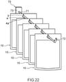
- Fig. 22 illustrates the pouches 10 hung on the hanging implement 70, the pouches 10 each including the hole 4 illustrated in Fig. 21 .
- the portion 4a of the packaging material that overlaps the hole 4 is pushed by the support 71 that has reached the hole 4 after passing through the communication part 5.
- the support 71 can be thus inserted into the hole 4 as illustrated in Fig. 22 .
- the foregoing description of the embodiment is directed to an example in which the hole 4 is located in the middle portion of the first-edge seal 21 in the second direction D2, and the communication part 5 extends from the hole 4 to the first edge 11.
- the hole 4 and the communication part 5 may be located near the third edge 13 relative to the middle portion of the first-edge seal 21 in the second direction D2.
- the communication part 5 may extend from the hole 4 to the third edge 13. In this case, the location where the communication part 5 connects with the hole 4 can be easily offset from the uppermost portion of the hole 4.
- the communication part 5 connects with the hole 4 at a location that is offset from the uppermost portion of the hole 4, this helps to avoid contact of the support 71 with the communication part 5 while the pouch 10 is hung on the hanging implement 70. This makes it possible to prevent or inhibit the support 71 from passing through the communication part 5 due to the self-weight of the pouch 10.
- the first edge 11 of the pouch 10 may include a first side 11a, and a second side 11b located near the containment part 8 relative to the first side 11a.
- the first side 11a and the second side 11b both extend in the second direction D2.
- the first side 11a may be located in the middle portion of the first edge 11 in the second direction D2.
- one second side 11b may be located near the third edge 13 relative to the first side 11a, and another second side 11b may be located near the fourth edge 14 relative to the first side 11a.
- the hole 4 and the communication part 5 may be provided in the first-edge seal 21 located between the first side 11a of the first edge 11 and the containment part 8.
- the outer edge of a portion of the pouch 10 located between the first side 11a of the first edge 11 and the containment part 8 includes a third side 11c, which extends from the first side 11a toward the containment part 8.
- the communication part 5 may extend from the hole 4 to the third side 11c.
- the location where the communication part 5 connects with the hole 4 can be easily offset from the uppermost portion of the hole 4. This makes it possible to prevent or inhibit the support 71 from passing through the communication part 5 due to the self-weight of the pouch 10.
- Fig. 25 is a cross-sectional view of a modification of the reinforcement 55.
- the reinforcement 55 may include a packaging material that includes at least a base layer 56 and a sealant layer 57.
- the reinforcement 55 may include a packaging material folded in such a way that the sealant layer 57 faces outward.
- the sealant layer 57 of the reinforcement 55 that is located near the first packaging material 30A, and the first sealant layer 61 of the first packaging material 30A may be integrated together through a heat seal process.
- the sealant layer 57 of the reinforcement 55 that is located near the second packaging material 30B, and the second sealant layer 62 of the second packaging material 30B may be integrated together through a heat seal process.
- the reinforcing part 21a includes four sheets of packaging material each including a base layer and a sealant layer.
- the reinforcing part 21a includes the following sheets of packaging material arranged in the order stated below from the first face 1 toward the second face 2: the first packaging material 30A; a packaging material constituting the reinforcement 55: a packaging material constituting the reinforcement 55; and the second packaging material 30B.
- the presence of the four sheets of packaging material in the reinforcing part 21a helps to increase the strength of the pouch 10 around the periphery of each of the hole 4 and the communication part 5.
- the packaging material constituting the reinforcement 55 may be identical to the first packaging material 30A or the second packaging material 30B. That is, the reinforcement 55 may be formed by using the first packaging material 30A or the second packaging material 30B. This enables efficient manufacture of the pouch 10 including the reinforcing part 21a.
- the reinforcing part 21a illustrated in Fig. 25 may have a layer structure represented below.
- the sealing layer adjacent to the first base layer is formed by the first sealant layer 61 and the sealant layer 57.
- the sealing layer adjacent to the second base layer is formed by the second sealant layer 62 and the sealant layer 57.
- the sealant layer 57 joined to the first sealant layer 61, and the sealant layer 57 joined to the second sealant layer 62 may be separate layers.
- the base layer 56 stacked on the sealant layer 57 joined to the first sealant layer 61, and the base layer 56 stacked on the sealant layer 57 joined to the second sealant layer 62 may be separate layers.
- Fig. 26 illustrates an exemplary method for manufacturing a pouch including the reinforcement illustrated in Fig. 25 .
- the first packaging material 30A and the second packaging material 30B are placed to face each other.
- the reinforcement 55 made of a packaging material folded with the sealant layer facing outward as described above is inserted in between the first packaging material 30A and the second packaging material 30B to thereby form a multilayer body.
- the multilayer body is heat sealed at a predetermined sealing temperature to form the first-edge seal 21, the third-edge seal 23, and the fourth-edge seal 24.
- the multilayer body is punched with a punching die to form the hole 4 and the communication part 5.
- the multilayer body is cut at locations in the first direction D1 that are to become the third edge 13 and the fourth edge 14. In this way, the pouch 10 including the reinforcing part 21a, the hole 4, and the communication part 5 can be obtained.
- the reinforcement 55 is depicted as being made of a folded packaging material in the example illustrated in Figs. 25 and 26 , this is not intended to be limiting.
- two sheets of packaging material each including a base layer and a sealant layer may be stacked with their sealant layers facing outward to thereby form the reinforcement 55.
- Such two sheets of packaging material may be obtained by folding up a single sheet of packing material and then cutting the sheet in the vicinity of the fold.
- the packaging material constituting the reinforcement 55 illustrated in Fig. 25 may include layers other than the base layer 56 and the sealant layer 57.
- the reinforcing part 21a extends in the second direction D2 so as to reach the third edge 13 and the fourth edge 14.
- the area over which the reinforcing part 21a extends is not particularly limited as long as the reinforcing part 21a surrounds the hole 4.
- the reinforcing part 21a may not reach the third edge 13 or the fourth edge 14.
- a seal where the first packaging material 30A and the second packaging material 30B are joined together may be located between the reinforcing part 21a, and the third edge 13 or the fourth edge 14.
- the pouch 10 includes the reinforcing part 21a surrounding the hole 4 in plan view.
- the pouch 10 may not include the reinforcing part 21a surrounding the hole 4.
- the first packaging material 30A and the second packaging material 30B such that the second region 20 has sufficient strength, it is possible to prevent or inhibit a region around the periphery of each of the hole 4 and the communication part 5 from deforming to cause the pouch 10 to fall off the hanging implement.
- the pouch 10 is a so-called four-side seal pouch with a seal provided along each of the first edge 11, the second edge 12, the third edge 13, and the fourth edge 14.
- the pouch 10 may not necessarily be a four-side seal pouch.
- the pouch 10 may be a so-called three-side seal pouch with a seal provided along three of the four edges including the first edge 11, the second edge 12, the third edge 13, and the fourth edge 14.
- Fig. 29 is a front view of a three-side seal pouch with no contents contained therein.
- Fig. 30 is a front view of the three-side seal pouch with its contents contained therein.
- the pouch 10 illustrated in each of Figs. 29 and 30 is formed by folding over a packaging material along the fourth edge 14.
- the pouch 10 includes the following seals: the first-edge seal 21 extending along the first edge 11; and the third-edge seal 23 extending along the third edge 13.
- the second-edge seal 22 is formed along the second edge 12 as illustrated in Fig. 30 .
- the first packaging material 30A constituting the first face 1, and the second packaging material 30B constituting the second face 2 are each formed by a single sheet of packaging material folded over along the fourth edge 14. Accordingly, the layer structure of the first packaging material 30A is identical to the layer structure of the second packaging material 30B.
- the first direction D1 may be the machine direction of the first packaging material 30A and the second packaging material 30B
- the second direction D2 may be the transverse direction.
- Fig. 31 is a front view of a modification of the pouch 10.
- the pouch 10 may be a gusseted pouch configured to be capable of standing by itself with the second edge 12 facing down.
- the pouch 10 includes, in addition to the first packaging material 30A constituting the first face 1 and the second packaging material 30B constituting the second face 2, a third packaging material located at or near the second edge 12 and constituting a third face 3.
- the third packaging material is folded over along a folding part 3f, and disposed between the first packaging material 30A and the second packaging material 30B in the folded state.
- the second direction D2 may be the machine direction of each of the first packaging material 30A, the second packaging material 30B, and the third packaging material
- the first direction D1 may be the transverse direction.
- the third packaging material constituting the third face 3 includes a base layer, and a sealant layer located adjacent to the inner face of the base layer.
- the second-edge seal 22 extending along the second edge 12 is formed by joining together the first sealant layer 61 of the first packaging material 30A and the sealant layer of the third packaging material, and by joining together the second sealant layer 62 of the second packaging material 30B and the sealant layer of the third packaging material.
- Fig. 32 is a front view of a modification of the pouch 10.
- the pouch 10 may be a pillow pouch including a fin seal part 7 extending in the first direction D1 from the first edge 11 to the second edge 12.
- the fin seal part 7 is located on the first face 1.
- the fin seal part 7 may be located on the second face 2.
- the first direction D1 may be the machine direction of the first packaging material 30A and the second packaging material 30B
- the second direction D2 may be the transverse direction.
- Fig. 33 is a cross-sectional view of the pouch 10 taken along a line C-C in Fig. 32 .
- the fin seal part 7 includes a base portion 7a located near the containment part 8, and a distal end portion 7b located opposite to the base portion 7a.
- the fin seal part 7 includes a seal located between the base portion 7a and the distal end portion 7b and where the respective first sealant layers 61 of two sheets of first packaging material 30A located at the first face 1 are joined together.
- the fin seal part 7 includes a seal located between the base portion 7a and the distal end portion 7b and where the respective second sealant layers 62 of two sheets of second packaging material 30B located at the second face are joined together.
- the base portion 7a of the fin seal part 7 may be located near the third edge 13 or the fourth edge 14 relative to the middle portion of the pouch 10 in the second direction D2.
- the base portion 7a of the fin seal part 7 is located near the third edge 13 relative to the middle portion of the pouch 10 in the second direction D2. This helps to ensure that the fin seal part 7 does not overlap the hole 4 and the communication part 5.
- the base portion 7a of the fin seal part 7 may be disposed in the middle portion of the pouch 10 in the second direction D2, and the hole 4 and the communication part 5 may be disposed near the third edge 13 or the fourth edge 14 relative to the middle portion of the pouch 10 in the second direction D2.
- Figs. 32 and 33 described above illustrate an example in which the fin seal part 7 does not overlap the hole 4 and the communication part 5.
- the fin seal part 7 may overlap the hole 4 and the communication part 5.
- the fin seal part 7 preferably has a larger dimension than the hole 4 in the second direction D2.
- the first direction D1 may be the machine direction of the first packaging material 30A and the second packaging material 30B
- the second direction D2 may be the transverse direction.
- the base portion 7a of the fin seal part 7 may be slightly offset toward the third edge 13 or the fourth edge 14 from the middle portion of the pouch 10 in the second direction D2. This configuration allows the fin seal part 7 to overlap the hole 4 and the communication part 5 while allowing the hole 4 and the communication part 5 to be positioned in the middle portion of the first-edge seal 21 in the second direction D2.
- reference sign K1 denotes the distance in the second direction D2 from the third edge 13 to the base portion 7a.
- Reference sign K2 denotes the distance in the second direction D2 from the fourth edge 14 to the base portion 7a.
- the distance K1 is greater than the distance K2.
- the base portion 7a is located near the fourth edge 14 relative to the middle portion of the pouch 10 in the second direction D2.
- the difference between the distance K1 and the distance K2 corresponds to the dimension of the hole 4.
- the difference between the distance K1 and the distance K2 is, for example, greater than or equal to 5 mm and less than or equal to 50 mm.
- the first-edge seal 21 may not include the reinforcing part 21a. Even in such a case, this modification, the pouch 10 can be provided with sufficient strength in a portion around the periphery of each of the hole 4 and the communication part 5. The reason for this is described below with reference to Fig. 35.
- Fig. 35 is a cross-sectional view of the pouch 10 taken along a line D-D in Fig. 34 .
- the fin seal part 7 includes two sheets of first packaging material 30A stacked on each other. Consequently, a portion of the pouch 10 around the periphery of the hole 4 includes the following sheets of packaging material arranged in the order stated below from the fin seal part 7 toward the second face 2: two sheets of first packaging material 30A constituting the fin seal part 7; the first packaging material 30A constituting the first face 1; and the second packaging material 30B constituting the second face 2. That is, a portion of the pouch 10 around the periphery of the hole 4 includes four sheets of packaging material each including a base layer and a sealant layer. This makes it possible to increase the strength of the pouch 10 around the periphery of each of the hole 4 and the communication part 5.
- Fig. 36 is a front view of a modification of the pouch 10.
- the pouch 10 may be a side gusset pouch having the fin seal part 7 and provided with a folding part 13f and a folding part 14f, the folding part 13f extending along the third edge 13, the folding part 14f extending along the fourth edge 14.
- a packaging material identical to the first packaging material 30A and the second packaging material 30B is folded over.
- the first direction D1 may be the machine direction of the first packaging material 30A and the second packaging material 30B
- the second direction D2 may be the transverse direction.
- Fig. 37 is a front view of a modification of the pouch 10.
- the pouch 10 may include a zipper tape 16 attached to the inner face of the first packaging material 30A and the inner face of the second packaging material 30B.
- the zipper tape 16 is located near the second edge 12 relative to the easy-opening means 15, and extends in the second direction D2.
- the zipper tape 16 includes, for example, a projecting tape attached to the inner face of the first packaging material 30A, and a recessed tape attached to the inner face of the second packaging material 30B and capable of mating engagement with the protruding tape.
- the zipper tape 16 provided to the pouch 10 allows for easy resealing of the pouch 10 after the pouch 10 is opened.
- the support 71 of the hanging implement 70 has the shape of a circle in cross-section.
- this is not intended to be limiting.
- the support 71 may have other shapes in cross-section.
- Fig. 38 is a perspective view of a modification of the hanging implement 70.
- the support 71 of the hanging implement 70 may include a flat face 71f located at the top.
- Fig. 39 is a cross-sectional view of the support 71 when inserted in the hole 4 of the pouch 10.
- the flat face 71f of the support 71 is configured to overlap the second portion 5b of the communication part 5 in the vertical direction when the support 71 is inserted in the hole 4 of the pouch 10.
- the flat face 71f has a dimension in the second direction D2 that is larger than the spacing between the first line 5x and the second line 5y at the location where the second portion 5b connects with the hole 4.
- the support 71 may have the shape of a triangle in cross-section.
- the support 71 by forming the support 71 such that one side of the triangle is located at an upper position, the flat face 71f of the support 71 and the second portion 5b of the communication part 5 can be made to overlap each other in the vertical direction.
- the support 71 is placed such that one side of its triangular cross-section is positioned uppermost in a horizontal manner, and one vertex opposite to the one side of the triangular cross-section is positioned lowermost.
- horizontal it suffices that the above-mentioned one side be positioned substantially horizontally, and the term conceptually includes technical errors at the time of manufacture or installation.
- Fig. 40 is a cross-sectional view of a modification of the support 71 of the hanging implement 70.
- the support 71 may have the shape of a hexagon in cross-section. In this case, by forming the support 71 such that one side of the hexagon is located at an upper position, the flat face 71f of the support 71 and the second portion 5b of the communication part 5 can be made to overlap each other in the vertical direction.
- Fig. 41 is a perspective view of a modification of the hanging implement 70.
- the support 71 may include the flat face 71f located at the top, and the restraint part 72 may have a circular cross-section.
- the cross-section of the restraint part 72 may differ in shape from the cross-section of the support 71.
- the circular cross-section of the restraint part 72 allows the support 71 to be easily passed through the hole 4 of the pouch 10 via the restraint part 72. As described above, it is also possible to directly pass the support 71 through the hole 4 via the communication part 5.
- Fig. 42 is a plan view of the lidded container 17 as seen from a lid 17a.
- the lidded container 17 includes a container 17b, which includes the containment part 8 and a flange 17c, and the lid 17a, which is joined to the flange 17c of the container 17b.
- the lidded container 17 has an outer edge that includes the first edge 11, the second edge 12 opposing the first edge 11 in the first direction D1, and the third edge 13 and the fourth edge 14, which extend between the first edge 11 and the second edge 12. That is, the outer edge of the lidded container 17 has the shape of a quadrangle.
- the shape of the outer edge of the lidded container 17 in plan view is not particularly limited.
- the outer edge of the lidded container 17 may have a circular shape in plan view.
- the lidded container 17 includes a seal where the inner face of a first packaging material constituting the lid 17a, and the inner face of a second packaging material constituting the container 17b are joined together.
- the seal on the lidded container 17 includes the first-edge seal 21 extending along the first edge 11, the second-edge seal 22 extending along the second edge 12, the third-edge seal 23 extending along the third edge 13, and the fourth-edge seal 24 extending along the fourth edge 14.
- first region 19 a region of the lidded container 17 that overlaps the containment part 8 in plan view is referred to as first region 19. Further, a region of the lidded container 17 located between the containment part 8 and the outer edge of the lidded container 17 and including a seal that joins the first packaging material and the second packaging material together is referred to as second region 20.
- the lidded container 17 includes the hole 4, which is located in the second region 20 and penetrates the first packaging material and the second packaging material.
- the hole 4 is located in the first-edge seal 21 of the second region 20 between the first edge 11 of the lidded container 17 and the containment part 8.
- the lidded container 17 includes the communication part 5, which extends from the hole 4 to the outer edge of the lidded container 17 and penetrates the first packaging material and the second packaging material.
- the communication part 5 extends to the first edge 11 from a portion of the hole 4 closest to the first edge 11.
- the hole 4 and the communication part 5 are identical in configuration to the hole 4 and the communication part 5 of the pouch 10, and thus not described in further detail below.
- Fig. 43 is a cross-sectional view of the lidded container 17 taken along a line E-E in Fig. 42 .
- Fig. 44 is an enlarged cross-sectional view of the first-edge seal 21 and the containment part 8 of the lidded container 17 illustrated in Fig. 43 .
- the first packaging material 30A constituting the lid 17a includes at least the first base layer 51, and the first sealant layer 61 located adjacent to the inner face of the first base layer 51.
- the first packaging material 30A constituting the lid 17a may be similar in configuration to the first packaging material 30A constituting the pouch 10.
- the second packaging material 30B constituting the container 17b includes at least the second base layer 52.
- a suitable exemplary material for the second base layer 52 is an unoriented plastic film such as a cast polypropylene film or an unoriented nylon film.
- the second base layer 52 may be made of a single layer, or may include a plurality of layers.
- the second base layer 52 may be a co-extrusion sheet including a first layer made of polypropylene, a second layer made of EVOH or nylon, and a third layer made of polypropylene.
- EVOH refers to an ethylene-vinyl alcohol copolymer.
- the second packaging material 30B may include layers other than the second base layer 52.
- the second packaging material 30B has a thickness of, for example, greater than or equal to 150 ⁇ m and less than or equal to 800 ⁇ m.
- the container 17b can be fabricated by processing the second packaging material 30B by sheet forming.
- Sheet forming is a method involving heating and softening a packaging material such as a sheet material, and pressing a die against the resulting material to form a desired shape in the sheet.
- vacuum forming, air-pressure forming, vacuum/air-pressure forming, or press forming may be employed.
- the container 17b may be formed by other methods such as injection molding.
- the first packaging material 30A constituting the lid 17a includes at least one layer located in both the first region 19 and the second region 20.
- the first base layer 51 and the first sealant layer 61 of the first packaging material 30A are located in both the first region 19 and the second region 20.
- the second packaging material 30B constituting the container 17b likewise includes at least one layer located in both the first region 19 and the second region 20.
- the second base layer 52 of the second packaging material 30B is located in both the first region 19 and the second region 20.
- the support 71 can be inserted into the hole 4 via the communication part 5. This allows the lidded container 17 to be attached to or removed from the support 71 at a desired location on the support 71.
- Fig. 45 is a cross-sectional view of a modification of the second packaging material 30B of the lidded container 17. As with Fig. 44 , Fig. 45 is an enlarged view of the first-edge seal and the containment part of the lidded container illustrated in Fig. 43 .
- the second packaging material 30B constituting the container 17b may include the second base layer 52, and the second sealant layer 62 located adjacent to the inner face of the second base layer 52.
- the second base layer 52 may include an oriented plastic film oriented along at least one axis, preferably along two axes.
- the second sealant layer 62 to be used may be the same as the second sealant layer 62 of the second packaging material 30B of the pouch 10.
- the second packaging material 30B has a thickness of, for example, greater than or equal to 60 ⁇ m and less than or equal to 200 ⁇ m.
- a portion of the second region 20 where the hole 4 is located preferably has a predetermined flexural rigidity in at least one direction.
- the above-mentioned portion preferably has a mean flexural rigidity of greater than or equal to 15 g ⁇ cm 2 /cm.
- the above-mentioned portion preferably has an initial flexural rigidity of greater than or equal to 22 g ⁇ cm 2 /cm.
- the specimen 80 is cut out from a portion of the second region 20 that has the same layer structure as the portion of the second region 20 where the hole 4 is located. This allows initial flexural rigidity and mean flexural rigidity to be measured in the machine direction and the transverse direction.
- the preferred ranges of values for the initial flexural rigidity and the mean flexural rigidity in the machine direction and the transverse direction are identical to those in the case of the pouch 10, and thus not described in further detail below.
- Fig. 46 is a plan view of the tube 18 as seen from the first face 1.
- the tube 18 includes a tubular body part 18a, and a mouth part 18b.
- a cap 18c may be attached to the mouth part 18b.
- the body part 18a is made of a packaging material.
- the body part 18a includes a first packaging material constituting the first face 1, and a second packaging material constituting the second face 2.
- the containment part 8 for containing contents is provided between the first face 1 and the second face 2.
- the first packaging material and the second packaging material are obtained by forming a single sheet of packaging material into a tubular form.
- the body part 18a of the tube 18 has an outer edge that includes the first edge 11, the second edge 12 opposing the first edge 11 in the first direction D1, and the third edge 13 and the fourth edge 14, which extend between the first edge 11 and the second edge 12.
- the body part 18a of the tube 18 includes a seal where the inner face of the first packaging material constituting the first face 1, and the inner face of the second packaging material constituting the second face 2 are joined together.
- the seal on the body part 18a includes the first-edge seal 21 extending along the first edge 11.
- the body part 18a of the tube 18 includes a joint 6, which extends on the first face 1 from the first edge 11 to the second edge 12 in the first direction D1.
- the joint 6 includes a seal where the inner face at one end of a single sheet of packaging material constituting each of the first packaging material and the second packaging material, and the outer face at the other end of the single sheet of packaging material are joined together.
- the joint 6 may be located on the second face 2.
- first region 19 a region of the body part 18a of the tube 18 that overlaps the containment part 8 in plan view is referred to as first region 19.
- second region 20 A region located between the containment part 8 and the outer edge of the body part 18a and including a seal that joins the first packaging material and the second packaging material together is referred to as second region 20.
- the body part 18a of the tube 18 includes the hole 4, which is located in the second region 20 and penetrates the first packaging material and the second packaging material.
- the hole 4 is located in the first-edge seal 21 of the second region 20 between the first edge 11 of the body part 18a and the containment part 8.
- the body part 18a includes the communication part 5, which extends from the hole 4 to the outer edge of the body part 18a and penetrates the first packaging material and the second packaging material.
- the communication part 5 extends to the first edge 11 from a portion of the hole 4 closest to the first edge 11.
- the hole 4 and the communication part 5 are identical in configuration to the hole 4 and the communication part 5 of the pouch 10, and thus not described in further detail below.
- Fig. 47 is a cross-sectional view of the body part 18a of the tube 18 taken along a line F-F in Fig. 46 .
- the first packaging material 30A constituting the first face 1 includes at least the first base layer 51, and the first sealant layer 61 located adjacent to the inner face of the first base layer 51.
- the first packaging material 30A may include a third sealant layer 63 located adjacent to the outer face of the first base layer 51.
- the first base layer 51 of the first packaging material 30A may be similar in configuration to the first base layer 51 of the first packaging material 30A that constitutes the pouch 10 or the lid 17a mentioned above.
- the first sealant layer 61 and the third sealant layer 63 may be similar in configuration to the first sealant layer 61 of the first packaging material 30A that constitutes the pouch 10 or the lid 17a mentioned above.
- the second packaging material 30B constituting the second face 2 includes at least the second base layer 52, and the second sealant layer 62 located adjacent to the inner face of the second base layer 52.
- the second packaging material 30B may include a fourth sealant layer 64 located adjacent to the outer face of the second base layer 52.
- the second base layer 52, the second sealant layer 62, and the fourth sealant layer 64 of the second packaging material 30B may be similar in their material, thickness, or other configuration to the first base layer 51, the first sealant layer 61, and the third sealant layer 63 of the first packaging material 30A.
- the thickness of each of the first packaging material 30A and the second packaging material 30B is, for example, greater than or equal to 150 ⁇ m.
- the thickness of each of the first packaging material 30A and the second packaging material 30B may be greater than or equal to 200 ⁇ m, or may be greater than or equal to 250 ⁇ m.
- the thickness of each of the first packaging material 30A and the second packaging material 30B may be less than or equal to 500 ⁇ m, may be less than or equal to 400 ⁇ m, or may be less than or equal to 300 ⁇ m.
- the first packaging material 30A constituting the first face 1 of the body part 18a includes at least one layer located in both the first region 19 and the second region 20.
- the first base layer 51, the first sealant layer 61, and the third sealant layer 63 of the first packaging material 30A are located in both the first region 19 and the second region 20.
- the second packaging material 30B constituting the second face 2 of the body part 18a likewise includes at least one layer located in both the first region 19 and the second region 20.
- the second base layer 52, the second sealant layer 62, and the fourth sealant layer 64 of the second packaging material 30B are located in both the first region 19 and the second region 20.
- the support 71 can be inserted into the hole 4 via the communication part 5. This allows the tube 18 to be attached to or removed from the support 71 at a desired location on the support 71.
- a portion of the second region 20 where the hole 4 is located preferably has a predetermined flexural rigidity in at least one direction.
- the above-mentioned portion preferably has a mean flexural rigidity of greater than or equal to 15 g ⁇ cm 2 /cm.
- the above-mentioned portion preferably has an initial flexural rigidity of greater than or equal to 22 g ⁇ cm 2 /cm.
- the specimen 80 is cut out from a portion of the second region 20 that has the same layer structure as the portion of the second region 20 where the hole 4 is located. This allows initial flexural rigidity and mean flexural rigidity to be measured in the machine direction and the transverse direction.
- the preferred ranges of values for the initial flexural rigidity and the mean flexural rigidity in the machine direction and the transverse direction are identical to those in the case of the pouch 10, and thus not described in further detail below.
- the modifications of the communication part 5 illustrated in Figs. 12 to 14 may be combined with the modifications of the pouch illustrated in Figs. 29 to 37 , may be combined with the lidded container 17 illustrated in each of Figs. 42 to 45 , or may be combined with the tube 18 illustrated in each of Figs. 46 and 47 .
- the modifications of the hole 4 illustrated in Figs. 15 to 21 may be combined with the modifications of the pouch illustrated in Figs. 29 to 37 , may be combined with the lidded container 17 illustrated in each of Figs. 42 to 45 , or may be combined with the tube 18 illustrated in each of Figs. 46 and 47 .
- the specimen 80 including four stacked sheets of packaging material was created. Each single sheet of packaging material has a thickness of 82 ⁇ m. The overall thickness of the specimen 80 was thus 328 ⁇ m.
- the specimen 80 described above has a layer structure that corresponds to the layer structure illustrated in Fig. 34 , that is, the layer structure of a region around the periphery of the hole 4 formed in the fin seal part 7, or to the layer structure illustrated in Fig. 30 , that is, the layer structure of a region around the periphery of the hole 4 formed in a region overlapping the reinforcement 55 made of a folded packing material.
- Each single sheet of packaging material has a layer structure represented below. OPP 20 / PE 10 / ALPET 12 / PE 10 / CPP 30
- the symbol "/" represents the boundary between adjacent layers.
- the layer at the left end represents a layer defining the outer face of the packaging material, and the layer at the right end represents a layer defining the inner face of the packaging material.
- POP means a biaxially-oriented polypropylene film.
- PE means a poly-olefin resin layer using polyethylene.
- APET means a biaxially-oriented PET film with a vapor-deposited aluminum layer.
- CPP means a cast polypropylene film. The numerals denote the thicknesses of the corresponding layers (unit: ⁇ m).
- the flexural rigidity of the specimen 80 in each of the machine direction and the transverse direction was measured.
- a pure-bending characteristic tester JTC-911BT manufactured by SMT Co., Ltd. was used as the measuring instrument. The measurement is performed under the environment of a temperature of 25°C and a relative humidity of 50%.
- the mean flexural rigidity in the machine direction was 28.1 g ⁇ cm 2 /cm, and the mean flexural rigidity in the transverse direction was 19.8 g ⁇ cm 2 /cm.
- the initial flexural rigidity in the machine direction was 55.0 g ⁇ cm 2 /cm, and the initial flexural rigidity in the transverse direction was 24.7 g ⁇ cm 2 /cm.
- the specimen 80 was created in the same manner as in Example A1, except that the specimen 80 is made up of two sheets of packaging material.
- the specimen 80 had a thickness of 164 ⁇ m.
- Example A1 the flexural rigidity of the specimen 80 in each of the machine direction and the transverse direction was measured.
- the mean flexural rigidity in the machine direction was 7.8 g ⁇ cm 2 /cm
- the mean flexural rigidity in the transverse direction was 9.5 g ⁇ cm 2 /cm.
- the initial flexural rigidity in the machine direction was 11.4 g ⁇ cm 2 /cm
- the initial flexural rigidity in the transverse direction was 14.2 g ⁇ cm 2 /cm.
- the specimen 80 made of a biaxially-oriented PET film was prepared.
- the specimen 80 had a thickness of 150 ⁇ m.
- Example A1 the flexural rigidity of the specimen 80 in each of the machine direction and the transverse direction was measured.
- the mean flexural rigidity in the machine direction was 14.7 g ⁇ cm 2 /cm
- the mean flexural rigidity in the transverse direction was 15.9 g ⁇ cm 2 /cm.
- the initial flexural rigidity in the machine direction was 21.2 g ⁇ cm 2 /cm
- the initial flexural rigidity in the transverse direction was 22.3 g ⁇ cm 2 /cm.
- the pouch 10 illustrated in Fig. 1A was fabricated by using the same packaging material as that used in Example A1. Specifically, the same packaging material as that used in Example A1 was used as each of the first packaging material 30A constituting the first face 1 and the second packaging material 30B constituting the second face 2. Further, the packaging material according to Example A1 folded in two as illustrated in Fig. 25 was used as the reinforcement 55 of the reinforcing part 21a.
- the pouch 10 had a thickness of 328 ⁇ m around the hole 4. At the location where the second portion 5b connects with the hole 4, the first line 5x and the second line 5y had a spacing W2 of 2 mm from each other. The hole 4 had a diameter of 8 mm.
- a load was applied to the pouch 10 with the hanging implement 70 inserted in the hole 4 of the pouch 10 to thereby measure the maximum value of load that the pouch 10 is able to withstand.
- the support 71 of the hanging implement which has a circular cross-section with a diameter of 6 mm, was inserted into the hole 4 located near the first edge 11 of the pouch 10.
- the second edge 12 located opposite to the first edge 11 was pulled upward by using a scale 90.
- a scale 90 was pulled upward.
- the scale used was PORTABLE ELECTRONIC SCALE WH-A04 manufactured by WeiHeng.
- the measurement was taken five times, and for each measurement, the maximum value of load applied to the scale was recorded. The results are illustrated in Fig. 49 .
- the mean of the measured maximum values of load was 143.2 g.
- the pouch 10 was fabricated in the same manner as in Example B1, except that the pouch 10 does not include the reinforcing part 21a.
- the pouch 10 had a thickness of 164 ⁇ m around the hole 4.
- Example B1 the maximum value of load that the pouch 10 is able to withstand was measured.
- the results are illustrated in Fig. 49 .
- the mean of the measured maximum values of load was 47.8 g.
- Example B1 Five panelists evaluated the stability of the pouch 10 hung on the support 71 of the hanging implement. The results are illustrated in Fig. 50 . Panelists 1 to 5 all evaluated the pouch 10 as "bad”. The evaluation "bad” means that the pouch 10 fell when a panelist simply touched the pouch 10.
- the tube 18 illustrated in Fig. 46 was fabricated by using a packaging material with a thickness of 334 ⁇ m.
- the tube 18 had a thickness of 668 ⁇ m around the hole 4.
- the first line 5x and the second line 5y had a spacing W2 of 2 mm from each other.
- the packaging material has a layer represented below. PEF 130 / PET 12 / ALPET 12 / PEF 180
- PET polyethylene film
- Example B1 the maximum value of load that the tube 18 is able to withstand was measured.
- the results are illustrated in Fig. 49 .
- the mean of the measured maximum values of load was 754.2 g.
- Example B1 Five panelists evaluated the stability of the tube 18 hung on the support 71 of the hanging implement. The results are illustrated in Fig. 50 . Panelists 1 to 5 all evaluated the tube 18 as “great”. The evaluation "great” means that the tube 18 did not fall when a panelist touched the tube 18, and that the pouch 10 hardly fell when the panelist twisted the pouch 10.
- a second embodiment is directed to providing a pouch that makes it possible to save labor associated with putting the pouch on display.
- the second embodiment provides a pouch having a containment part formed by joining a first packaging material and a second packaging material together, the first packaging material being located at a first face of the pouch, the second packaging material being located at a second face of the pouch, the pouch including:
- the communication part may include a slit.
- the communication part may include the slit connected to the hole, and a notch connecting the slit and the outer edge of the pouch.
- the communication part may be contiguous with a top end of the hole.
- the communication part may be located in the middle portion of the outer edge of the pouch in a direction in which the first edge extends.
- the second embodiment makes it possible to provide a pouch that makes it possible to save labor associated with putting the pouch on display.
- Fig. 51A is a front view of the pouch 10 as seen from the first face 1.
- Fig. 51B is a back view of the pouch 10 as seen from the second face 2.
- components other than the communication part 5 are identical to those of the pouch illustrated in Figs. 1A and 1B .
- the communication part 5 connects the hole 4 and the outer edge of the pouch 10 located opposite to the containment part 8, and penetrates the pouch 10.
- the communication part 5 penetrates the pouch 10 from the first face 1 to the second face 2, and is provided so as to connect the first edge 11 and the hole 4. More specifically, the communication part 5 is a slit extending from the first edge 11 to the hole 4.
- the hole 4 is positioned such that its entire periphery is surrounded by the reinforcing part 21a.
- the thickness of the reinforcing part 21a around the periphery of the hole 4 is greater than the thicknesses of other portions of the second region 20. This leads to increased strength around the periphery of the hole 4. This helps to prevent or inhibit tearing of the periphery of the hole 4 caused by the weight of the pouch 10 exerted on the support 71 of the hanging implement 70.
- the communication part 5 is provided so as to connect the first edge 11 and the hole 4. Consequently, by passing the support 71 through the communication part 5, the support 71 can be placed within the hole 4. This eliminates the need to pass the distal end of the support 71 through the hole 4, which significantly saves labor associated with putting the pouch 10 on display.
- the reinforcing part 21a has a layer structure identical to the layer structure of the reinforcing part 21a according to the first embodiment or its modifications described above. That is, the reinforcing part 21a may have any one of the layer structures a) to c) below.
- Figs. 52A to 52E are each a partial enlarged view of the region indicated by reference sign G and enclosed by an alternate long and two short dashes line in Fig. 51A .
- the illustration on the left depicts the above-mentioned region with the support 71 not inserted
- the illustration on the right depicts the above-mentioned region with the support 71 inserted.
- Fig. 52A depicts the configuration illustrated in Fig. 51A in which the communication part 5 is a slit. In this case, the spacing between the first line 5x and the second line 5y of the communication part 5 is substantially zero.
- Figs. 52B to 52E depict modifications of the hole 4 and the communication part 5.
- the communication part 5 is the notch 5e.
- the spacing between the first line 5x and the second line 5y is greater than zero.
- the spacing between the first line 5x and the second line 5y may be constant.
- the spacing between the first line 5x and the second line 5y may be set to any suitable value not exceeding the maximum width of the corresponding support 71. If the communication part 5 illustrated in Fig. 52A and the communication part 5 illustrated in Fig. 52B are compared, the communication part 5 in the form of the slit illustrated in Fig. 52A is able to withstand a longer duration of hanging than is the communication part 5 in the form of the notch illustrated in Fig. 52B .
- the hole 4 and the communication part 5 are disposed adjacent to each other in a direction parallel to the first edge 11.
- the location (boundary) where the hole 4 and the communication part 5 connect with each other is indicated by a dashed line that extends vertically. Accordingly, in Fig. 52C , the hole 4 is located on the left-hand side of the dashed line, and the communication part 5 is located on the righthand side of the dashed line.
- the hole 4 has a shape bounded by the dashed boundary, a circular arc in a lower portion of the hole 4, and two straight sides extending diagonally upward from left and right portions of the hole 4.
- the point of intersection of the two straight sides extending diagonally upward from left and right portions of the hole 4 is the top end of the hole 4.
- the communication part 5 has a shape bounded by the dashed boundary, a circular arc in a lower portion of the communication part 5, and two straight sides having constant spacing therebetween and extending to the first edge 11.
- the top end of the hole 4 is located above the top end of the location where the hole 4 and the communication part 5 connect with each other (indicated by the vertically extending dashed line in Fig. 52C ).
- the communication part 5 includes the notch 5e including a portion where the spacing between the first line 5x and the second line 5y decreases with increasing distance from the first edge 11 toward the hole 4.
- the spacing between the first line 5x and the second line 5y decreases with increasing proximity to the hole 4, and becomes zero at the point of connection with the hole 4. That is, the communication part 5 is a notch in the shape of a triangle with a base parallel to the first edge 11 and an apex located at the point of connection with the hole 4.
- the communication part 5 includes a vertically extending slit that connects the triangular notch illustrated in the example in Fig. 52D and the hole 4. That is, in the example illustrated in Fig. 52E , the communication part 5 includes the notch 5e where the spacing between the first line 5x and the second line 5y decreases with increasing distance from the first edge 11 toward the hole 4, and the slit 5d connecting the notch 5e and the hole 4.
- the length of the slit 5d in this case is not particularly limited, from the viewpoint of ease of manufacture and strength of the location where the slit is provided, the length of the slit 5d is preferably about 1 to 5 mm, optimally about 3 mm. In the example illustrated in Fig.
- the communication part 5 includes the triangular notch 5e and the vertically extending slit 5d as described above.
- two sides of the triangular notch that connect to the first edge 11 can be also regarded as an outer edge of the pouch 10 that extends contiguously from the first edge 11.
- the communication part 5 includes only the slit 5d that connects the outer edge of the pouch and the hole 4.
- Figs. 53A to 53D are each a partial enlarged view of the region indicated by reference sign G and enclosed by an alternate long and two short dashes line in Fig. 51A .
- the first packaging material 30A and the second packaging material 30B that are located in the area overlapping the hole 4 may be left to remain while being coupled to the second region 20 located around the periphery of the hole 4. That is, the portion 4a of each packaging material that overlaps the hole 4 may be coupled via the coupling part 4z to the second region 20 located around the periphery of the hole 4.
- the shapes of the communication part 5 in Figs. 53A, 53B , 53C, and 53D are respectively identical to the shapes of the communication part 5 in Figs. 52A, 52B , 52D, and 52E .
- hanging of the pouch 10 involves passing the support 71 through the communication part 5, and pushing, at the top end of the hole 4, a portion including a base layer and a sealing layer from above with the support 71 to thereby insert the support 71 into the hole 4.
- the hole 4 and the communication part 5 according to the second embodiment and each of its modifications may be combined with the modifications of the pouch illustrated in Figs. 29 to 37 , may be combined with the lidded container 17 illustrated in each of Figs. 42 to 45 , or may be combined with the tube 18 illustrated in each of Figs. 46 and 47 .
- a third embodiment is directed to providing a pouch that makes it possible to save labor associated with putting the pouch on display.
- the third embodiment provides a pouch having a containment part formed by joining a first packaging material and a second packaging material together, the first packaging material being located at a first face of the pouch, the second packaging material being located at a second face of the pouch, the pouch including:
- the communication part may include a slit.
- the communication part may include the slit connected to the hole, and a notch connecting the slit and the outer edge of the pouch.
- the communication part may be contiguous with a top end of the hole.
- the communication part may connect a portion of the outer edge of the pouch other than the corner portion, and the hole.
- the third embodiment makes it possible to provide a pouch that makes it possible to save labor associated with putting the pouch on display.
- Fig. 54A is a front view of the pouch 10 as seen from the first face 1.
- Fig. 54B is a back view of the pouch 10 as seen from the second face 2.
- components other than the hole 4 and the communication part 5 are identical to those of the pouch illustrated in Figs. 1A and 1B .
- the hole 4 is provided in a corner portion of the pouch 10.
- a corner portion of the pouch 10 refers to the region indicated by reference sign H and enclosed by an alternate long and two short dashes line in Fig. 54A .
- the corner portion includes the corner where the first edge 11 and the fourth edge 14 meet, and an area in the vicinity of the corner.
- the communication part 5 connects a top end 10U of the pouch 10 and the hole 4, and penetrates the pouch 10.
- the top end 10U is the point of intersection of the first edge 11 and the fourth edge 14, and is a corner of the pouch 10.
- the communication part 5 is a slit extending from the top end 10U to the hole 4.
- the hole 4 is positioned such that its entire periphery is surrounded by the reinforcing part 21a.
- the thickness of the reinforcing part 21a around the periphery of the hole 4 is greater than the thicknesses of other portions of the second region 20. This leads to increased strength around the periphery of the hole 4. This helps to prevent or inhibit tearing of the periphery of the hole 4 caused by the weight of the pouch 10 exerted on the support 71 of the hanging implement 70.
- the communication part 5 is provided so as to connect the top end 10U and the hole 4. Consequently, by passing the support 71 through the communication part 5, the support 71 can be placed within the hole 4. This eliminates the need to pass the distal end of the support 71 through the hole 4, which significantly saves labor associated with putting the pouch 10 on display.
- the reinforcing part 21a has a layer structure identical to the layer structure of the reinforcing part 21a according to the first embodiment or its modifications described above. That is, the reinforcing part 21a may have any one of the layer structures a) to c) below.
- Figs. 55A to 55D are each a partial enlarged view of the region indicated by reference sign H and enclosed by an alternate long and two short dashes line in Fig. 54A .
- the illustration on the left depicts the above-mentioned region with the support 71 not inserted
- the illustration on the right depicts the above-mentioned region with the support 71 inserted.
- Fig. 55A depicts the configuration illustrated in Fig. 54A in which the communication part 5 is a slit. In this case, the spacing between the first line 5x and the second line 5y of the communication part 5 is substantially zero.
- Figs. 55B to 55D depict modifications of the hole 4 and the communication part 5.
- the communication part 5 is the notch 5e.
- the spacing between the first line 5x and the second line 5y is greater than zero.
- the spacing between the first line 5x and the second line 5y may be constant.
- the spacing between the first line 5x and the second line 5y may be set to any suitable value not exceeding the maximum width of the corresponding support 71. If the communication part 5 illustrated in Fig. 55A and the communication part 5 illustrated in Fig. 55B are compared, the communication part 5 in the form of the slit illustrated in Fig. 55A is able to withstand a longer duration of hanging than is the communication part 5 in the form of the notch illustrated in Fig. 55B .
- the communication part 5 includes the notch 5e including a portion where the spacing between the first line 5x and the second line 5y decreases with increasing distance from the first edge 11 toward the hole 4.
- the spacing between the first line 5x and the second line 5y decreases with increasing proximity to the hole 4, and becomes zero at the point of connection with the hole 4.
- the communication part 5 is a notch in the shape of a triangle with a base and an apex, the base being a side extending in a direction (left-right direction in Fig. 54A ) transverse to a direction in which the containment part 8 and the hole 4 are connected, the apex being located at the point of connection with the hole 4.
- the communication part 5 includes a slit that connects the triangular notch illustrated in the example in Fig. 55C and the hole 4. That is, in the example illustrated in Fig. 55D , the communication part 5 includes the notch 5e where the spacing between the first line 5x and the second line 5y decreases with increasing distance from the outer edge of the pouch 10 toward the hole 4, and the slit 5d connecting the notch 5e and the hole 4.
- the length of the slit 5d in this case is not particularly limited, from the viewpoint of ease of manufacture and strength of the location where the slit is provided, the length of the slit 5d is preferably about 1 to 5 mm, optimally about 3 mm.
- Figs. 56A to 56D are each a partial enlarged view of the region indicated by reference sign H and enclosed by an alternate long and two short dashes line in Fig. 54A .
- the first packaging material 30A and the second packaging material 30B that are located in the area overlapping the hole 4 may be left to remain while being coupled to the second region 20 located around the periphery of the hole 4. That is, the portion 4a of each packaging material that overlaps the hole 4 may be coupled via the coupling part 4z to the second region 20 located around the periphery of the hole 4.
- the shapes of the communication part 5 in Figs. 56A, 56B , 56C, and 56D are respectively identical to the shapes of the communication part 5 in Figs. 55A, 55B , 55D , and 55E.
- hanging of the pouch 10 involves passing the support 71 through the communication part 5, and pushing, at the top end of the hole 4, a portion including a base layer and a sealing layer from above with the support 71 to thereby insert the support 71 into the hole 4.
- the communication part 5 may be formed to extend contiguously to the hole 4 from a portion of the outer edge of the pouch 10 other than a corner portion.
- Figs. 57A and 57B are respectively a front view and a back view of the pouch 10 including the communication part 5 according to a modification.
- the hole 4 has a polygonal shape.
- the communication part 5 is a notch extending from the first edge 11 to the hole 4.
- the boundary between the hole 4 and the communication part 5 is indicated by a dashed line.
- the spacing between the first line 5x and the second line 5y may be substantially constant from the first edge 11 to the hole 4.
- the spacing between the first line 5x and the second line 5y may be greater than or equal to the width of the hole 4. If the spacing between the first line 5x and the second line 5y is greater than or equal to the width of the hole 4, the support 71 can be easily inserted into the hole 4 from the first edge 11. In the example illustrated in Figs. 57A and 57B , in hanging the pouch 10, the support 71 is passed through the communication part 5 from the first edge 11 to thereby insert the support 71 into the hole 4 from the left side.
- the hole 4 and the communication part 5 according to the third embodiment and its modifications may be combined with the modifications of the pouch illustrated in Figs. 29 to 37 , may be combined with the lidded container 17 illustrated in each of Figs. 42 to 45 , or may be combined with the tube 18 illustrated in each of Figs. 46 and 47 .
- Fig. 58A and 58B are respectively a front view and a back view of a pillow pouch that employs the hole 4 and the communication part 5 according to the third embodiment and its modifications.
Landscapes
- Engineering & Computer Science (AREA)
- Mechanical Engineering (AREA)
- Packages (AREA)
- Bag Frames (AREA)
Abstract
Description
- The present invention relates to a pouch, a lidded container, and a tube that each include a containment part for containing contents.
- As disclosed in, for example,
PTL 1, it is common to provide an upper portion of a pouch with a pre-formed through-hole, and pass a hanging implement such as a hook through the through-hole to hang the pouch on the hanging implement for display. - PTL 1:
Japanese Unexamined Patent Application Publication No. 2003-11990 - Hanging a plurality of pouches described in
PTL 1 on the hanging implement requires an operation that involves first passing the through-hole of each pouch through the distal end portion of the hanging implement, and then moving the pouch along a support of the hanging implement. - It is an object of the present invention to provide a pouch, a lidded container, a tube, and other packages that allow the above-mentioned issue to be effectively addressed.
- According to the present invention, there is provided a pouch, the pouch having a containment part formed by joining a first packaging material and a second packaging material together, the first packaging material being located at a first face of the pouch, the second packaging material being located at a second face of the pouch, the pouch including:
- a first region overlapping the containment part in plan view;
- a second region located between the containment part and an outer edge of the pouch in plan view, the second region including a seal that joins the first packaging material and the second packaging material together;
- a hole located in the second region and penetrating the first packaging material and the second packaging material; and
- a communication part extending from the hole to the outer edge of the pouch and penetrating the first packaging material and the second packaging material,
- wherein the first packaging material includes at least one layer located in both the first region and the second region,
- wherein the second packaging material includes at least one layer located in both the first region and the second region,
- wherein an outline of the communication part that extends from the hole to the outer edge of the pouch includes a first line and a second line, and
- wherein the communication part includes
- a first portion including a portion where the first line and the second line have a spacing from each other that decreases with increasing distance from the outer edge of the pouch toward the hole, and
- a second portion located between the first portion and the hole and including a portion where the first line and the second line have a spacing from each other of less than or equal to 2.0 mm.
- In one exemplary embodiment of the pouch according to the present invention, in the second portion of the communication part, the first line and the second line are not in contact with each other.
- In one exemplary embodiment of the pouch according to the present invention, in the second portion of the communication part, the first line and the second line are at least partially in contact with each other.
- In one exemplary embodiment of the pouch according to the present invention, a portion of the communication part where the first line and the second line are not in contact with each other is longer than a portion of the communication part where the first line and the second line are in contact with each other.
- In one exemplary embodiment of the pouch according to the present invention, a specimen cut out from a portion of the second region where the hole is located has a mean flexural rigidity of greater than or equal to 15 [g·cm2/cm] in a machine direction, the specimen including at least the first packaging material and the second packaging material.
- In one exemplary embodiment of the pouch according to the present invention, the second region includes:
- an outer-edge-side seal extending along the outer edge of the pouch;
- a containment-part-side seal in contact with the containment part in plan view; and
- a reinforcing part located between the outer-edge-side seal and the containment-part-side seal and surrounding the hole, the reinforcing part being thicker than the outer-edge-side seal and the containment-part-side seal.
- In one exemplary embodiment of the pouch according to the present invention, the reinforcing part includes a reinforcement located between the first packaging material and the second packaging material.
- According to the present invention, there is provided a lidded container, the lidded container having a containment part sealed by joining a first packaging material and a second packaging material together, the first packaging material constituting a lid, the second packaging material constituting a container, the lidded container including:
- a first region overlapping the containment part in plan view;
- a second region located between the containment part and an outer edge of each of the lid and the container in plan view, the second region including a seal that joins the first packaging material and the second packaging material together;
- a hole located in the second region and penetrating the first packaging material and the second packaging material; and
- a communication part extending from the hole to the outer edge of each of the lid and the container and penetrating the first packaging material and the second packaging material,
- wherein the first packaging material includes at least one layer located in both the first region and the second region,
- wherein the second packaging material includes at least one layer located in both the first region and the second region,
- wherein an outline of the communication part that extends from the hole to the outer edge of each of the lid and the container includes a first line and a second line, and
- wherein the communication part includes
- a first portion including a portion where the first line and the second line have a spacing from each other that decreases with increasing distance from the outer edge of each of the lid and the container toward the hole, and
- a second portion located between the first portion and the hole and including a portion where the first line and the second line have a spacing from each other of less than or equal to 2.0 mm.
- In one exemplary embodiment of the lidded container according to the present invention, a specimen cut out from a portion of the second region where the hole is located has a mean flexural rigidity of greater than or equal to 15 [g·cm2/cm] in a machine direction, the specimen including at least the first packaging material and the second packaging material.
- According to the present invention, there is provided a tube, the tube having a containment part formed by joining a first packaging material and a second packaging material together, the first packaging material being located at a first face of the tube, the second packaging material being located at a second face of the tube, the tube including:
- a first region overlapping the containment part in plan view;
- a second region located between the containment part and an outer edge of the tube in plan view, the second region including a seal that joins the first packaging material and the second packaging material together;
- a hole located in the second region and penetrating the first packaging material and the second packaging material; and
- a communication part extending from the hole to an outer edge of each of the tube and penetrating the first packaging material and the second packaging material,
- wherein the first packaging material includes at least one layer located in both the first region and the second region,
- wherein the second packaging material includes at least one layer located in both the first region and the second region the second packaging material,
- wherein an outline of the communication part that extends from the hole to the outer edge of the tube includes a first line and a second line, and
- wherein the communication part includes
- a first portion including a portion where the first line and the second line have a spacing from each other that decreases with increasing distance from the outer edge of the tube toward the hole, and
- a second portion located between the first portion and the hole and including a portion where the first line and the second line have a spacing from each other of less than or equal to 2.0 mm.
- In one exemplary embodiment of the tube according to the present invention, a specimen cut out from a portion of the second region where the hole is located has a mean flexural rigidity of greater than or equal to 15 [g·cm2/cm] in a machine direction, the specimen including at least the first packaging material and the second packaging material.
- The present invention makes it possible to provide a pouch, a lidded container, a tube, and other packages that can be easily inserted onto a hanging implement, and are resistant to falling when hung on the hanging implement.
-
- [
Fig. 1A] Fig. 1A is a front view of a pouch according to a first embodiment as seen from a first face of the pouch. - [
Fig. 1B] Fig. 1B is a back view of the pouch according to the first embodiment as seen from a second face of the pouch. - [
Fig. 2] Fig. 2 is an enlarged front view of the region indicated by reference sign B and enclosed by an alternate long and two short dashes line inFig. 1A . - [
Fig. 3] Fig. 3 is a cross-sectional view of the pouch taken along a line A-A inFig. 1A . - [
Fig. 4] Fig. 4 illustrates a method for measuring the flexural rigidity of a specimen cut out from the pouch. - [
Fig. 5] Fig. 5 illustrates the method for measuring the flexural rigidity of the specimen cut out from the pouch. - [
Fig. 6] Fig. 6 is a cross-sectional view of an exemplary packaging material constituting the pouch. - [
Fig. 7] Fig. 7 is a cross-sectional view of an exemplary packaging material constituting the pouch. - [
Fig. 8] Fig. 8 illustrates an exemplary method for manufacturing the pouch. - [
Fig. 9A] Fig. 9A is a front view of the pouch illustrated inFig. 1A with a containment part sealed. - [
Fig. 9B] Fig. 9B is a back view of the pouch illustrated inFig. 1B with the containment part sealed. - [
Fig. 10] Fig. 10 illustrates a plurality of pouches hung on a hanging implement. - [
Fig. 11A] Fig. 11A illustrates an exemplary operation of hanging the pouch on the hanging implement. - [
Fig. 11B] Fig. 11B illustrates an exemplary operation of hanging the pouch on the hanging implement. - [
Fig. 12] Fig. 12 is a front view of a modification of a communication part provided in a second region. - [
Fig. 13] Fig. 13 is a front view of a modification of the communication part provided in the second region. - [
Fig. 14] Fig. 14 is a front view of a modification of the communication part provided in the second region. - [
Fig. 15] Fig. 15 is a front view of a modification of a hole provided in the second region. - [
Fig. 16] Fig. 16 is a front view of a modification of the hole provided in the second region. - [
Fig. 17] Fig. 17 is a front view of a modification of the hole provided in the second region. - [
Fig. 18] Fig. 18 is a front view of a modification of the hole provided in the second region. - [
Fig. 19] Fig. 19 is a front view of a modification of the hole provided in the second region. - [
Fig. 20] Fig. 20 is a front view of a modification of the hole provided in the second region. - [
Fig. 21] Fig. 21 is a front view of a modification of the hole provided in the second region. - [
Fig. 22] Fig. 22 illustrates pouches hung on the hanging implement and each including the hole illustrated inFig. 21 . - [
Fig. 23] Fig. 23 is a front view of a modification of each of the hole and the communication part that are provided in the second region. - [
Fig. 24] Fig. 24 is a front view of a modification of each of the hole and the communication part that are provided in the second region. - [
Fig. 25] Fig. 25 is a cross-sectional view of a modification of a reinforcement. - [
Fig. 26] Fig. 26 illustrates an exemplary method for manufacturing a pouch including the reinforcement illustrated inFig. 25 . - [
Fig. 27] Fig. 27 is a front view of a modification of a reinforcing part. - [
Fig. 28] Fig. 28 is a front view of a modification of the pouch. - [
Fig. 29] Fig. 29 is a front view of a modification of the pouch. - [
Fig. 30] Fig. 30 is a front view of the pouch illustrated inFig. 29 with the containment part sealed. - [
Fig. 31] Fig. 31 is a front view of a modification of the pouch. - [
Fig. 32] Fig. 32 is a front view of a modification of the pouch. - [
Fig. 33] Fig. 33 is a cross-sectional view of the pouch taken along a line C-C inFig. 32 . - [
Fig. 34] Fig. 34 is a front view of a modification of the pouch. - [
Fig. 35] Fig. 35 is a cross-sectional view of the pouch taken along a line D-D inFig. 34 . - [
Fig. 36] Fig. 36 is a front view of a modification of the pouch. - [
Fig. 37] Fig. 37 is a front view of a modification of the pouch. - [
Fig. 38] Fig. 38 is a perspective view of a modification of the hanging implement. - [
Fig. 39] Fig. 39 is a cross-sectional view of a modification of a support of the hanging implement. - [
Fig. 40] Fig. 40 is a cross-sectional view of the support of the hanging implement. - [
Fig. 41] Fig. 41 is a perspective view of a modification of the hanging implement. - [
Fig. 42] Fig. 42 is a plan view of an exemplary lidded container that includes the hole and the communication part. - [
Fig. 43] Fig. 43 is a cross-sectional view of the lidded container taken along a line E-E inFig. 42 . - [
Fig. 44] Fig. 44 is an enlarged cross-sectional view of a first-edge seal and the containment part of the lidded container illustrated inFig. 43 . - [
Fig. 45] Fig. 45 is a cross-sectional view of a modification of a second packaging material of the lidded container. - [
Fig. 46] Fig. 46 is a front view of an exemplary tube that includes the hole and the communication part. - [
Fig. 47] Fig. 47 is a cross-sectional view of the tube taken along a line F-F inFig. 46 . - [
Fig. 48] Fig. 48 illustrates a method for measuring the maximum value of load that a package is able to withstand. - [
Fig. 49] Fig. 49 illustrates the measurements of the maximum value of load. - [
Fig. 50] Fig. 50 illustrates the results of evaluation made by panelists. - [
Fig. 51A] Fig. 51A is a front view of a pouch according to a second embodiment as seen from the first face of the pouch. - [
Fig. 51B] Fig. 51B is a back view of the pouch according to the second embodiment as seen from the second face of the pouch. - [
Fig. 52A] Fig. 52A is an enlarged front view of the region indicated by reference sign G and enclosed by an alternate long and two short dashes line inFig. 51A . - [
Fig. 52B] Fig. 52B is a front view of a modification of the communication part. - [
Fig. 52C] Fig. 52C is a front view of a modification of the communication part. - [
Fig. 52D] Fig. 52D is a front view of a modification of the communication part. - [
Fig. 52E] Fig. 52E is a front view of a modification of the communication part. - [
Fig. 53A] Fig. 53A is a front view of a modification of the communication part. - [
Fig. 53B] Fig. 53B is a front view of a modification of the communication part. - [
Fig. 53C] Fig. 53C is a front view of a modification of the communication part. - [
Fig. 53D] Fig. 53D is a front view of a modification of the communication part. - [
Fig. 54A] Fig. 54A is a front view of a pouch according to a third embodiment as seen from the first face of the pouch. - [
Fig. 54B] Fig. 54B is a back view of the pouch according to the third embodiment as seen from the second face of the pouch. - [
Fig. 55A] Fig. 55A is an enlarged front view of the region indicated by reference sign H and enclosed by an alternate long and two short dashes line inFig. 54A . - [
Fig. 55B] Fig. 55B is a front view of a modification of the communication part. - [
Fig. 55C] Fig. 55C is a front view of a modification of the communication part. - [
Fig. 55D] Fig. 55D is a front view of a modification of the communication part. - [
Fig. 56A] Fig. 56A is a front view of a modification of the communication part. - [
Fig. 56B] Fig. 56B is a front view of a modification of the communication part. - [
Fig. 56C] Fig. 56C is a front view of a modification of the communication part. - [
Fig. 56D] Fig. 56D is a front view of a modification of the communication part. - [
Fig. 57A] Fig. 57A is a front view of a modification of the pouch according to the third embodiment. - [
Fig. 57B] Fig. 57B is a back view of a modification of the pouch according to the third embodiment. - [
Fig. 58A] Fig. 58A is a front view of a modification of the pouch according to the third embodiment. - [
Fig. 58B] Fig. 58B is a back view of a modification of the pouch according to the third embodiment. - A first embodiment of the present invention is described below with reference to
Figs. 1 to 11B . In the accompanying drawings, for ease of illustration and understanding, the scales, the length-to-width dimensional ratios, and other dimensional features in the drawings are changed and exaggerated as appropriate from the actual values. - As for terms and values that are used herein to define shapes, geometric conditions, and their extents or degrees, for example, terms such as "parallel", "orthogonal", and "identical" and values such as lengths and angles, these terms and values are not limited to their strict meanings but are to be construed as including a range of variations that allow for similar expected functions.
-
Fig. 1 is a front view of apouch 10 as seen from afirst face 1 of thepouch 10.Fig. 1B is a back view of thepouch 10 as seen from asecond face 2 of thepouch 10 located opposite to thefirst face 1.Figs. 1A and1B each depict thepouch 10 prior to being filled with the contents, that is, with no contents contained therein. As used with reference to the first embodiment, the term pouch conceptually includes not only a pouch with no contents contained therein but also a pouch with contents contained therein. - The
pouch 10 has acontainment part 8 for containing contents. Thecontainment part 8 is a space located between a first packaging material, which constitutes thefirst face 1, and a second packaging material, which constitutes thesecond face 2. Thecontainment part 8 is defined by the first packaging material, the second packaging material, and a seal where the first packaging material and the second packaging material are joined together. In each of front views and back views of thepouch 10 such asFigs 1A and1B , as well as plan views of a lidded container and front views of a tube that will be described later, the seal is shaded with diagonal lines. As illustrated inFig. 1A , when viewed along the normal to the first packaging material constituting thefirst face 1, thecontainment part 8 is located inside the seal. In the following description, viewing a pouch, a lidded container, a tube, or other packages along the normal to the first packaging material is also referred to simply as plan view. - The terms "first packaging material" and "second packaging material" mentioned above are used to merely divide individual packaging materials from each other according to their positional relationship, and are not intended to limit the manner in which the packaging materials are provided in manufacturing the
pouch 10. For example, thepouch 10 may be manufactured by using a single sheet of packaging material including the first packaging material and the second packaging material that are provided contiguously, or may be manufactured by using a total of two sheets of packaging material including a single sheet of first packaging material and a single sheet of second packaging material. - A region of a package that overlaps the
containment part 8 in plan view is hereinafter referred to asfirst region 19. A region of the package located between thecontainment part 8 and the outer edge of the package and including the seal that joins the first packaging material and the second packaging material together is hereinafter referred to assecond region 20. - The contents to be contained in the
containment part 8 of a package such as a pouch, a lidded container, or a tube are not particularly limited. Thecontainment part 8 of the package is capable of containing objects in various forms as its contents, such as liquids, powders, granulates, and solids. The contents may be food products, or may be non-food products. - The shape of the
pouch 10 is described below. In the example illustrated inFigs. 1A and1B , thepouch 10 has an outer edge in the shape of a quadrangle. As used herein, the term quadrangle conceptually includes not only shapes with angular corners but also shapes whose corners are chamfered into an outwardly convex arcuate or curved shape. - The outer edge of the pouch includes a
first edge 11, asecond edge 12 opposing thefirst edge 11 in a first direction D1, and athird edge 13 and afourth edge 14, which extend between thefirst edge 11 and thesecond edge 12. Thethird edge 13 and thefourth edge 14 may be opposed to each other in a second direction D2 orthogonal to the first direction D1. Thefirst edge 11 may be located at the upper side of thepouch 10 when thepouch 10 is hung. In this case, the first direction D1 is the vertical direction, and the second direction D2 is the horizontal direction. - The seal is described below. The seal on the
second region 20 of thepouch 10 illustrated inFigs. 1A and1B includes a first-edge seal 21 extending along thefirst edge 11, a third-edge seal 23 extending along thethird edge 13, and a fourth-edge seal 24 extending along thefourth edge 14. In plan view, the first-edge seal 21, the third-edge seal 23, and the fourth-edge seal 24 may or may not be in contact with the outer edge of thepouch 10. InFigs. 1A and1B , a lower portion of thepouch 10 located below an alternate long and short dash line is a to-be-second-edge-seal part 22b, which is to become a second-edge seal 22 later. - The seal on the
pouch 10 may be provided with easy-opening means 15 for tearing the packaging material constituting the pouch to allow opening of the pouch. For example, as illustrated inFigs. 1A and1B , the easy-opening means 15 may include anotch 15a, which extends from thethird edge 13 in the second direction D2 and penetrates the third-edge seal 23. The easy-opening means 15 may include a half-cut line formed in the third-edge seal 23 by use of laser machining, a cutter, or other means. The easy-opening means 15 may be formed at or near thefourth edge 14. - The
pouch 10 includes ahole 4, which is located in thesecond region 20 and penetrates the first packaging material and the second packaging material. In the example illustrated inFigs. 1A and1B , thehole 4 is located in thesecond region 20 between thefirst edge 11 of thepouch 10 and thecontainment part 8. Thehole 4 is a hole into which the support of a hanging implement described later is to be inserted. In the example illustrated inFigs. 1A and1B , thehole 4 has a circular outline. - The
pouch 10 includes acommunication part 5, which extends from thehole 4 to the outer edge of thepouch 10 and penetrates the first packaging material and the second packaging material. In the example illustrated inFigs. 1A and1B , thecommunication part 5 extends to thefirst edge 11 from a portion of thehole 4 located closest to thefirst edge 11. Thecommunication part 5 allows the support of the hanging implement described later to pass therethrough from thefirst edge 11 toward thehole 4. In other words, thecommunication part 5 is capable of connecting thefirst edge 11 and thehole 4. - As illustrated in
Figs. 1A and1B , an outline of thecommunication part 5 that extends from thehole 4 to the outer edge of thepouch 10 includes afirst line 5x and asecond line 5y. In the example illustrated inFigs. 1A and1B , thefirst line 5x and thesecond line 5y are not in contact with each other. Thecommunication part 5 described above is obtained by punching out a portion of thesecond region 20 located between the outer edge of thepouch 10 and thehole 4 by use of a punching die. In this case, thecommunication part 5 is also referred to as notch. -
Fig. 2 is an enlarged front view of the region indicated by reference sign B and enclosed by an alternate long and two short dashes line inFig. 1A . As illustrated inFig. 2 , thecommunication part 5 is divided into afirst portion 5a located near thefirst edge 11, and asecond portion 5b located between thefirst portion 5a and thehole 4. InFig. 2 , reference sign W denotes the spacing between thefirst line 5x and thesecond line 5y. The spacing W refers to the distance between thefirst line 5x and thesecond line 5y in a direction orthogonal to amiddle line 5z running in the middle between thefirst line 5x and thesecond line 5y. - The
second portion 5b includes a portion where the spacing W is less than or equal to 2.0 mm. For example, thesecond portion 5b is defined as a portion of thecommunication part 5 extending to thehole 4 from a location where the spacing W is 2.0 mm. In this case, thefirst portion 5a is defined as a portion of thecommunication part 5 where the spacing W is greater than 2.0 mm. - As illustrated in
Fig. 2 , thefirst portion 5a may include a portion where the spacing W decreases with increasing distance from thefirst edge 11 toward thehole 4. For example, thefirst line 5x of thefirst portion 5a may include a straight line inclined relative to themiddle line 5z such that its proximity to themiddle line 5z increases with increasing distance from thefirst edge 11 toward thehole 4. Thesecond line 5y of thefirst portion 5a may likewise include a straight line inclined relative to themiddle line 5z such that its proximity to themiddle line 5z increases with increasing distance from thefirst edge 11 toward thehole 4. Each straight line inclined relative to themiddle line 5z may extend to thesecond portion 5b. In one example, each of the straight lines inclined relative to themiddle line 5z may reach thehole 4. In this case, thesecond portion 5b likewise includes a portion where the spacing W decreases with increasing distance from thefirst edge 11 toward thehole 4. - In
Fig. 2 , reference sign W1 denotes the spacing between thefirst line 5x and thesecond line 5y at a location where thefirst portion 5a connects with thefirst edge 11. Reference sign W2 denotes the spacing between thefirst line 5x and thesecond line 5y at a location where thesecond portion 5b connects with thehole 4. The spacing W1 is greater than the spacing W2. - The spacing W1 is dimensioned such that the hanging implement on which to hang the
pouch 10 can easily enter thecommunication part 5. The spacing W1 is, for example, greater than or equal to 2.0 mm. The spacing W1 may be greater than or equal to 3.0 mm, or may be greater than or equal to 4.0 mm. An excessively large spacing W1, however, reduces the area of thesecond region 20 located between thefirst edge 11 and thehole 4. This makes thesecond region 20 more prone to deformation. With this in mind, the spacing W1 may be less than or equal to 10.0 mm, may be less than or equal to 8.0 mm, or may be less than or equal to 6.0 mm. - The spacing W2 is dimensioned to prevent or inhibit the hanging implement inserted in the
hole 4 from passing through thecommunication part 5 due to the self-weight of thepouch 10. The spacing W2 is, for example, less than or equal to 2.0 mm. The spacing W2 may be less than or equal to 1.5 mm, may be less than or equal to 1.0 mm, or may be less than or equal to 0.5 mm. Setting the spacing W2 to less than or equal to 2 mm makes it possible to prevent or inhibit thesecond region 20 facing thesecond portion 5b and in contact with the hanging implement from twisting and thus allowing the hanging implement to pass through thecommunication part 5. - As illustrated in
Fig. 2 , thefirst line 5x and thesecond line 5y may include acurved portion 5c. Thecurved portion 5c may define thefirst line 5x and thesecond line 5y at the location where thefirst portion 5a connects with thefirst edge 11. Thecurved portion 5c is curved to be convex toward thefirst edge 11. The presence of thecurved portion 5c described above facilitates entry of the hanging implement into thecommunication part 5. - The curvature radius R of the
curved portion 5c at the location where thefirst portion 5a connects with thefirst edge 11 is, for example, greater than or equal to 3.0 mm. The curvature radius R may be greater than or equal to 4.0 mm, or may be greater than or equal to 5.0 mm. Further, the curvature radius R of thecurved portion 5c at the location where thefirst portion 5a connects with thefirst edge 11 may be less than or equal to 10.0 mm, may be less than or equal to 8.0 mm, or may be less than or equal to 6.0 mm. - In
Fig. 2 , reference signs L1 and L2 respectively denote the length of thefirst portion 5a and the length of thesecond portion 5b in a direction in which themiddle line 5z extends. As illustrated inFig. 2 , the length L1 of thefirst portion 5a may be greater than the length L2 of thesecond portion 5b. For example, the length L1 of thefirst portion 5a may be greater than 1.0 times, may be greater than or equal to 1.1 times, may be greater than or equal to 1.2 times, or may be greater than or equal to 1.5 times the length L2 of thesecond portion 5b. Alternatively, although not illustrated, the length L1 of thefirst portion 5a may be less than the length L2 of thesecond portion 5b. For example, the length L1 of thefirst portion 5a may be less than 1.0 times, may be less than or equal to 0.9 times, may be less than or equal to 0.8 times, or may be less than or equal to 0.6 times the length L2 of thesecond portion 5b. - Upon hanging the
pouch 10 on the hanging implement, a portion of the packaging material constituting thepouch 10 and located around the periphery of each of thehole 4 and thecommunication part 5 receives a reaction force from the hanging implement that is caused by the self-weight of thepouch 10. At this time, if the packaging material has a small strength relative to the force exerted from the hanging implement, this may result in the package material undergoing, for example, deformation or cracking. This may cause thepouch 10 to fall off the hanging implement. With this in mind, thesecond region 20 of thepouch 10 may include a reinforcingpart 21a. - In the example illustrated in
Figs. 1A and1B , two dashed lines extending in the second direction D2 in an upper portion of thepouch 10 represent the upper and lower ends of the reinforcingpart 21a. The reinforcingpart 21a is located in the first-edge seal 21 where thehole 4 is provided. The presence of the reinforcingpart 21a makes it possible to increase the strength of thepouch 10 around the periphery of each of thehole 4 and thecommunication part 5. This helps to prevent or inhibit thepouch 10 from undergoing, for example, deformation or cracking. - As illustrated in
Figs. 1A and1B , the reinforcingpart 21a may be located between an outer-edge-side seal 21b and a containment-part-side seal 21c. The outer-edge-side seal 21b is a seal extending along thefirst edge 11 of thepouch 10. The outer-edge-side seal 21b may or may not in contact with thefirst edge 11 in plan view. The containment-part-side seal 21c is a seal that is in contact thecontainment part 8 in plan view. The reinforcingpart 21a, the outer-edge-side seal 21b, and the containment-part-side seal 21c constitute the first-edge seal 21. - The reinforcing
part 21a surrounds thehole 4 in plan view. As illustrated inFigs. 1A and1B , the reinforcingpart 21a may extend in the second direction D2 so as to reach thethird edge 13 and thefourth edge 14. -
Fig. 3 is a cross-sectional view of thesecond region 20 of the pouch taken along a line A-A inFig. 1A . As illustrated inFig. 3 , the reinforcingpart 21a is thicker than the outer-edge-side seal 21b and the containment-part-side seal 21c. The difference between the thickness T3 of the reinforcingpart 21a and each of the thickness T4 of the outer-edge-side seal 21b and the thickness T5 of the containment-part-side seal 21c is, for example, greater than or equal to 50 µm. The above-mentioned difference may be greater than or equal to 70 µm, or may be greater than or equal to 100 µm. - As illustrated in
Fig. 3 , the reinforcingpart 21a may include areinforcement 55 located between the inner face of afirst packaging material 30A constituting thefirst face 1, and the inner face of asecond packaging material 30B constituting thesecond face 2. In the outer-edge-side seal 21b and the containment-part-side seal 21c, the inner face of thefirst packaging material 30A and the inner face of thesecond packaging material 30B may be joined together. This configuration allows the reinforcingpart 21a to have a thickness that is greater than the thickness T4 of the outer-edge-side seal 21b and the thickness T5 of the containment-part-side seal 21c by an amount equal to the thickness of thereinforcement 55. The term "inner face" refers to a face of a packaging material such as thefirst packaging material 30A or thesecond packaging material 30B that is located adjacent to thecontainment part 8. - As illustrated in
Fig. 3 , thefirst packaging material 30A may include afirst base layer 51, and afirst sealant layer 61 located adjacent to the inner face of thefirst base layer 51. Thesecond packaging material 30B may include asecond base layer 52, and asecond sealant layer 62 located adjacent to the inner face of thesecond base layer 52. In the outer-edge-side seal 21b and the containment-part-side seal 21c, thefirst sealant layer 61 of thefirst packaging material 30A, and thesecond sealant layer 62 of thesecond packaging material 30B may be joined together. For example, thefirst sealant layer 61 and thesecond sealant layer 62 may be integrated together through a heat seal process. - In the reinforcing
part 21a, thefirst sealant layer 61 of thefirst packaging material 30A, and thesecond sealant layer 62 of thesecond packaging material 30B may be joined to thereinforcement 55. For example, thefirst sealant layer 61, thereinforcement 55, and thesecond sealant layer 62 may be integrated together through a heat seal process. Alternatively, thefirst sealant layer 61 and thereinforcement 55 may not be joined together. Thesecond sealant layer 62 and thereinforcement 55 may not be joined together. Even in such cases, the reinforcingpart 21a is sandwiched between the outer-edge-side seal 21b and the containment-part-side seal 21c in plan view, and thus in the reinforcingpart 21a, the spacing between the inner face of thefirst packaging material 30A and the inner face of thesecond packaging material 30B can be limited to be within a predetermined range. - Suitable exemplary materials for a type of the
reinforcement 55 that is joined to thefirst sealant layer 61 and thesecond sealant layer 62 include materials described later as exemplary materials for thefirst sealant layer 61. Suitable exemplary materials for a type of thereinforcement 55 that is not joined to thefirst sealant layer 61 and thesecond sealant layer 62 include: films or sheets made of, for example, polyethylene terephthalate, polybutylene terephthalate, or polypropylene; and paper. The thickness of thereinforcement 55 is, for example, greater than or equal to 50 µm. The thickness of thereinforcement 55 may be greater than or equal to 70 µm, or may be greater than or equal to 100 µm. The thickness of thereinforcement 55 may be less than or equal to 1000 µm, may be less than or equal to 500 µm, or may be less than or equal to 300 µm. - For a case where the
reinforcement 55 is joined to thefirst sealant layer 61 and thesecond sealant layer 62, thereinforcement 55, and thefirst sealant layer 61 and thesecond sealant layer 62 may form an integral sealing layer in the reinforcingpart 21a. Thefirst sealant layer 61 and thesecond sealant layer 62 may form an integral sealing layer in the outer-edge-side seal 21b and the containment-part-side seal 21c. InFig. 3 , reference sign T1 denotes the thickness of the sealing layer located in the reinforcingpart 21a. Reference sign T2 denotes the thickness of the sealing layer located in the outer-edge-side seal 21b and the containment-part-side seal 21c. The thickness T1 is greater than the thickness T2. To ensure that the reinforcingpart 21a retains sufficient strength, the thickness T1 of the sealing layer in the reinforcingpart 21a is preferably greater than or equal to 100 µm. The sealing layer in the outer-edge-side seal 21b, and the sealing layer in the containment-part-side seal 21c are substantially equal to each other in thickness. For example, the thickness T1 of the sealing layer in the reinforcingpart 21a may be 136 µm, and the thickness T2 of the sealing layer in each of the outer-edge-side seal 21b and the containment-part-side seal 21c may be 36 µm. - For a case where the
reinforcement 55 is joined to thefirst sealant layer 61 and thesecond sealant layer 62, the reinforcingpart 21a may have a layer structure represented below.
first base layer / sealing layer / second base layer - As described above, the sealing layer is formed by the
first sealant layer 61, the reinforcingpart 21a, and thesecond sealant layer 62. - For a case where the
reinforcement 55 is not joined to thefirst sealant layer 61 and thesecond sealant layer 62, the reinforcingpart 21a may have a layer structure represented below.
first base layer / sealing layer / reinforcement / sealing layer / second base layer - The sealing layer adjacent to the first base layer is formed by the
first sealant layer 61. The sealing layer adjacent to the second base layer is formed by thesecond sealant layer 62. - Reference is now made to preferred mechanical characteristics possessed by the
second region 20 that is provided with thehole 4. Preferably, a portion of thesecond region 20 where thehole 4 is located has a predetermined flexural rigidity in at least one direction. For example, the above-mentioned portion preferably has a mean flexural rigidity of greater than or equal to 15 g·cm2/cm. The above-mentioned portion preferably has an initial flexural rigidity of preferably greater than or equal to 22 g·cm2/cm. - Flexural rigidity is a parameter representing a measure of the stiffness of a film. Reference is now made to
Figs. 4 and 5 to describe a method for measuring flexural rigidity. - To measure flexural rigidity, first, a
specimen 80 is cut out from a portion of thesecond region 20 that has the same layer structure as the portion of thesecond region 20 where thehole 4 is located. As illustrated inFig. 4 , thespecimen 80 has the shape of a square with sides each having a length M1. The length M1 is 10 mm. The direction of each side of thespecimen 80 is set in accordance with the direction in which to measure flexural rigidity. For example, for a case where flexural rigidity is to be measured in the second direction D2, which is the machine direction of thepouch 10 illustrated inFig. 1A , thespecimen 80 includes sides extending in parallel to the second direction D2. - Subsequently, as illustrated in
Fig. 4 , opposing sides of thespecimen 80 are held by using afirst clamp 86 and asecond clamp 87 of a measuringinstrument 85. To measure flexural rigidity in the second direction D2, thespecimen 80 is held such that sides of thespecimen 80 extending in the second direction D2 extend from thefirst clamp 86 to thesecond clamp 87. The spacing M3 between thefirst clamp 86 and thesecond clamp 87 is 10 mm. - Subsequently, the
first clamp 86 is tilted relative to thesecond clamp 87 so as to bend thespecimen 80 into a curved shape. The initial flexural rigidity and mean flexural rigidity of thespecimen 80 can be calculated based on the bending moment exerted on thespecimen 80 at this time. Initial flexural rigidity refers to the bending moment exerted on thespecimen 80 when thespecimen 80 is bent into a curved shape from a flat shape. Mean flexural rigidity refers to the mean value of bending moments exerted on thespecimen 80 during a single execution of the process of bending thespecimen 80 into a curved shape from a flat shape until thespecimen 80 has a set curvature. The set curvature is 2.5/cm. The rate of change in curvature is 0.1/cm·s. - Initial flexural rigidity and mean flexural rigidity are measured for each of five
specimens 80, and their respective mean values are used as initial flexural rigidity and mean flexural rigidity according to the first embodiment. - The mean flexural rigidity of the
specimen 80 in the machine direction is preferably greater than or equal to 15 g·cm2/cm. The mean flexural rigidity of thespecimen 80 in the machine direction may be greater than or equal to 20 g·cm2/cm, may be greater than or equal to 25 g·cm2/cm, or may be greater than or equal to 30 g·cm2/cm. An excessively high mean flexural rigidity, however, reduces the manufacturability or ease of handling of thepouch 10. With this in mind, the mean flexural rigidity of thespecimen 80 in the machine direction may be less than or equal to 50 g·cm2/cm, may be less than or equal to 45 g·cm2/cm, may be less than or equal to 40 g·cm2/cm, or may be less than or equal to 35 g·cm2/cm. - The mean flexural rigidity of the
specimen 80 in the transverse direction orthogonal to the machine direction is preferably greater than or equal to 16 g·cm2/cm. The mean flexural rigidity of thespecimen 80 in the transverse direction may be greater than or equal to 18 g·cm2/cm, may be greater than or equal to 20 g·cm2/cm, or may be greater than or equal to 22 g·cm2/cm. The mean flexural rigidity of thespecimen 80 in the transverse direction may be less than or equal to 40 g·cm2/cm, may be less than or equal to 35 g·cm2/cm, may be less than or equal to 30 g·cm2/cm, or may be less than or equal to 25 g·cm2/cm. - The initial flexural rigidity of the
specimen 80 in the machine direction is preferably greater than or equal to 22 g·cm2/cm. The initial flexural rigidity of thespecimen 80 in the machine direction may be greater than or equal to 25 g·cm2/cm, may be greater than or equal to 30 g·cm2/cm, or may be greater than or equal to 40 g·cm2/cm. The initial flexural rigidity of thespecimen 80 in the machine direction may be less than or equal to 70 g·cm2/cm, may be less than or equal to 60 g·cm2/cm, may be less than or equal to 50 g·cm2/cm, or may be less than or equal to 45 g·cm2/cm. - The initial flexural rigidity of the
specimen 80 in the transverse direction is preferably greater than or equal to 23 g·cm2/cm. The initial flexural rigidity of thespecimen 80 in the transverse direction may be greater than or equal to 25 g·cm2/cm, may be greater than or equal to 28 g·cm2/cm, or may be greater than or equal to 30 g·cm2/cm. The initial flexural rigidity of thespecimen 80 in the transverse direction may be less than or equal to 70 g·cm2/cm, may be less than or equal to 60 g·cm2/cm, may be less than or equal to 50 g·cm2/cm, or may be less than or equal to 40 g·cm2/cm. - As an instrument for measuring flexural rigidity, a pure-bending characteristic tester JTC-911BT manufactured by SMT Co., Ltd. can be used. The flexural rigidity is measured under the environment of a temperature of 25°C and a relative humidity of 50%.
- According to the first embodiment, the
second region 20 is provided with the reinforcingpart 21a including thereinforcement 55. This makes it possible to increase the flexural rigidity of a portion of thesecond region 20 where thehole 4 is located. This helps to prevent or inhibit a region around the periphery of each of thehole 4 and thecommunication part 5 from deforming to cause thepouch 10 to fall off the hanging implement. - Reference is now made in detail to the
first packaging material 30A and thesecond packaging material 30B. - The
first packaging material 30A includes at least one layer located in both thefirst region 19 and thesecond region 20. For example, as illustrated inFig. 3 , thefirst base layer 51 and thefirst sealant layer 61 of thefirst packaging material 30A are located in both thefirst region 19 and thesecond region 20. - As with the
first packaging material 30A, thesecond packaging material 30B also includes at least one layer located in both thefirst region 19 and thesecond region 20. For example, as illustrated inFig. 3 , thesecond base layer 52 and thesecond sealant layer 62 of thesecond packaging material 30B are located in both thefirst region 19 and thesecond region 20. - The layer structure of each of the
first packaging material 30A and thesecond packaging material 30B is described below in detail.Fig. 6 is a cross-sectional view of the layer structure of thefirst packaging material 30A. - As illustrated in
Fig. 6 , thefirst packaging material 30A includes at least thefirst base layer 51, and thefirst sealant layer 61 located adjacent to the inner face of thefirst base layer 51. Thefirst packaging material 30A may include a first bonding layer 65 for bonding thefirst base layer 51 to another layer such as thefirst sealant layer 61. - Suitable materials for the
first base layer 51 may include: a polyester film such as a polyethylene terephthalate film or a polybutylene terephthalate film; a polyamide film such as a nylon film; a plastic film such as a polypropylene film; and paper. A plastic film that constitutes thefirst base layer 51 is preferably oriented biaxially. - If the
first base layer 51 includes a plastic film, thefirst base layer 51 has a thickness of, for example, greater than or equal to 10 µm and less than or equal to 50 µm. Paper that constitutes thefirst base layer 51 has a basis weight of, for example, greater than or equal to 20 g/m2 and less than or equal to 100 g/m2. - Suitable materials for the
first sealant layer 61 may include polyolefin resins such as polyethylene, polypropylene, ethylene-vinyl acetate copolymers, ethylene-propylene block copolymers, and propylene-ethylene block copolymers. Thefirst sealant layer 61 may include an unoriented sealant film. - The thickness of the
first sealant layer 61 may be greater than or equal to 15 µm, or may be greater than or equal to 18 µm. The thickness of thefirst sealant layer 61 may be less than or equal to 80 µm, may be less than or equal to 60 µm, may be less than or equal to 40 µm, or may be less than or equal to 30 µm. - The first bonding layer 65 may be an adhesive layer, or may be a bonding resin layer. The adhesive layer can be formed by a known method, for example, dry lamination. The bonding resin layer includes thermoplastic resin. The bonding resin layer can be formed by a known method, for example, melt extrusion lamination or sandwich lamination.
-
Fig. 7 is a cross-sectional view of another exemplary layer structure of thefirst packaging material 30A. As illustrated inFig. 7 , thefirst packaging material 30A may further include a first additional layer 53. Thefirst packaging material 30A may include a third bonding layer 67 for bonding the first additional layer 53 to another layer. - The first additional layer 53 is provided to impart some characteristics to the
first packaging material 30A. For example, the first additional layer 53 may include the film described above as an example of thefirst base layer 51. In this case, the presence of the first additional layer 53 helps to increase the strength of thefirst packaging material 30A. The material of a plastic film that constitutes the first additional layer 53 may be identical to or different from the material of a plastic film that constitutes thefirst base layer 51. - The first additional layer 53 may include a metallic foil of aluminum or other metals. This allows for enhanced gas barrier property or light-blocking property of the
first packaging material 30A. The first additional layer 53 may include a resin layer with gas barrier property, examples of which include ethylene-vinyl alcohol copolymers (EVOH), polyvinylidene chloride resins (PVDC), or aromatic polyamides such as nylon MXD6. - As illustrated in
Fig. 7 , the first additional layer 53 may be located between thefirst base layer 51 and thefirst sealant layer 61. Alternatively, although not illustrated, the first additional layer 53 may be located adjacent to the outer face of thefirst base layer 51. - As with the first bonding layer 65, the third bonding layer 67 may be an adhesive layer, or may be a bonding resin layer.
- The
first packaging material 30A may include a print layer. The print layer is a layer on which to form any desired prints such as letters, numerals, designs, geometric figures, symbols, or patterns for purposes including decoration, indication of the contents, indication of best-before date, manufacturer or producer, seller or distributor, or other such information, and providing other indications or a sense of beauty. The print layer is formed by printing ink including a binder and a pigment. - A plastic film included in the
first packaging material 30A may be provided with a vapor-deposited layer of a metal such as aluminum, a vapor-deposited layer of a metal oxide such as an aluminum oxide, or a vapor-deposited layer of an inorganic oxide such as a silicon oxide. Such a vapor-deposited layer may be stacked over thefirst base layer 51, may be stacked over thefirst sealant layer 61, or may be stacked over the first additional layer 53. - The layers constituting the
first packaging material 30A are stacked by use of a method such as dry lamination or melt extrusion. Thefirst packaging material 30A may further include other layers not illustrated in the drawings. - The
second packaging material 30B includes at least thesecond base layer 52, and thesecond sealant layer 62 located adjacent to the inner face of thesecond base layer 52. As with thefirst packaging material 30A illustrated inFig. 6 , thesecond packaging material 30B may include the following layers arranged in the order stated below from the outer side toward the inner side of thesecond packaging material 30B: thesecond base layer 52, a second bonding layer 66, and thesecond sealant layer 62. Thesecond base layer 52, the second bonding layer 66, and thesecond sealant layer 62 of thesecond packaging material 30B may be similar in their material, thickness, or other configuration to thefirst base layer 51, the first bonding layer 65, and thefirst sealant layer 61 of thefirst packaging material 30A. - As with the
first packaging material 30A illustrated inFig. 7 , thesecond packaging material 30B may include the following layers arranged in the order stated below from the outer side toward the inner side of thesecond packaging material 30B: thesecond base layer 52, the second bonding layer 66, a second additional layer 54, a fourth bonding layer 68, and thesecond sealant layer 62. Thesecond base layer 52, the second bonding layer 66, the second additional layer 54, the fourth bonding layer 68, and thesecond sealant layer 62 of thesecond packaging material 30B may be similar in their material, thickness, or configuration to thefirst base layer 51, the first bonding layer 65, the first additional layer 53, the third bonding layer 67, and thefirst sealant layer 61 of thefirst packaging material 30A. - The layer structure of the
first packaging material 30A may be identical to or different from the layer structure of thesecond packaging material 30B. Thefirst packaging material 30A and thesecond packaging material 30B are also collectively referred to aspackaging material 30. - The thickness of each of the
first packaging material 30A and thesecond packaging material 30B is, for example, greater than or equal to 30 µm. The thickness of each of thefirst packaging material 30A and thesecond packaging material 30B may be greater than or equal to 40 µm, or may be greater than or equal to 45 µm. The thickness of each of thefirst packaging material 30A and thesecond packaging material 30B may be less than or equal to 100 µm, may be less than or equal to 80 µm, or may be less than or equal to 60 µm. - Reference is now made to several preferred specific examples of the
packaging material 30. Thepackaging material 30 is not limited to the specific examples described below but may have other configurations. - OPP (oriented polypropylene film) 20 µm / print layer / AC /
PE 10 µm / VMPET 12 µm / AC /PE 10 µm / CPP (cast polypropylene film) 18 µm -
OPP 20 µm / adhesive layer /VMCPP 30 µm - PET (polyethylene terephthalate) 12 µm / adhesive layer /
VMCPP 30 µm -
OPP 20 µm / adhesive layer /CPP 18 µm - ONY (oriented nylon film) 15 µm / PE (polyethylene film) 30 µm
- print layer /
paper 50 µm /PE 10 µm / VMPET 12 µm / AC /PE 10 µm /CPP 18 µm - print layer /
paper 50 µm /PE 10 µm /aluminum foil 7 µm /PE 30 µm -
PET 12 µm /PE 15 µm /aluminum foil 7 µm /PE 30 µm - "AC" means anchor coating layer. The anchor coating layer is a layer formed by applying an anchor coating agent onto a predetermined layer or film and then drying the resulting layer or film.
- "VMPET" means a PET film with a vapor-deposited layer of a metal such as aluminum stacked thereon.
- Reference is now made to a method for manufacturing the
pouch 10. First, as illustrated inFig. 6 , thefirst packaging material 30A and thesecond packaging material 30B are placed to face each other. Thereinforcement 55 is inserted in between thefirst packaging material 30A and thesecond packaging material 30B to form a multilayer body. In this state, the multilayer body is heat sealed at a predetermined sealing temperature in regions corresponding to thefirst edge 11, thethird edge 13, and thefourth edge 14 to thereby form the first-edge seal 21, the third-edge seal 23, and the fourth-edge seal 24. A region of the multilayer body overlapping thereinforcement 55 becomes the reinforcingpart 21a mentioned above. Each of thefirst packaging material 30A, thesecond packaging material 30B, and thereinforcement 55 may be in the form of a long roll stock extending in the second direction D2 inFig. 6 . - Subsequently, the multilayer body is punched with a punching die to form the
hole 4 and thecommunication part 5. Further, the multilayer body is cut at locations in the first direction D1 that are to become thethird edge 13 and thefourth edge 14. In this way, thepouch 10 including the reinforcingpart 21a, thehole 4, and thecommunication part 5 illustrated inFigs. 1A and1B can be obtained. - Subsequently, the
containment part 8 of thepouch 10 is filled with the contents through anopening 9 located near thesecond edge 12. Then, at a location near thesecond edge 12, the inner face of thefirst packaging material 30A, and the inner face of thesecond packaging material 30B are heat sealed at a predetermined sealing temperature to form the second-edge seal 22. In this way, as illustrated inFigs. 9A and9B , thepouch 10 with its contents contained and sealed therein can be obtained. - Reference is now made to an example of how to use the
pouch 10. The figure illustrates a plurality ofpouches 10 hung on a hanging implement 70. The hanging implement 70 includes at least asupport 71 on which to hang eachpouch 10. Thesupport 71 is, for example, a rod, which is inserted into thehole 4 of thepouch 10. - The hanging implement 70 may include a
restraint part 72 connected to one end of thesupport 71. Therestraint part 72 is inclined relative to thesupport 71 such that therestraint part 72 is displaced upward relative to thesupport 71 with increasing distance from the one end of thesupport 71. In other words, therestraint part 72 is inclined so as to extend downward in the longitudinal direction toward thesupport 71. The presence of therestraint part 72 helps to prevent or inhibit thepouch 10 from falling off the one end of thesupport 71.Reference sign 74 denotes the boundary part between thesupport 71 and therestraint part 72. Thesupport 71 and therestraint part 72 may be formed by a single component that is bent in theboundary part 74 such that the orientation of its longitudinal direction changes in theboundary part 74. - The hanging implement 70 may include a
fixed part 73 connected to the other end of thesupport 71. Thefixed part 73 is a component in the form of a flat plate with a predetermined thickness. Thefixed part 73 may be formed such that when thefixed part 73 is placed with its surface oriented in parallel to the vertical direction, thesupport 71 and therestraint part 72 are both directed vertically downward toward theboundary part 74. As with conventional hanging implements, the fixedpart 73 has predetermined mounting means provided on its back. The mounting means allows the fixedpart 73 to be mounted to a fixture or to a display rack or shelf with the surface of the fixedpart 73 oriented in parallel to the vertical direction. -
Figs. 11A and 11B each illustrate an exemplary operation of hanging thepouch 10 on the hanging implement 70. This operation is performed by, for example, an employee of a store that sells thepouch 10. - The employee first brings the
communication part 5 of thepouch 10 into contact with thesupport 71 of the hanging implement 70. According to the first embodiment, thefirst line 5x and thesecond line 5y have a large spacing from each other at the location where thefirst portion 5a connects with thefirst edge 11. This facilitates positioning of thecommunication part 5 of thepouch 10 with respect to thesupport 71. As illustrated inFig. 11A , the presence of thecurved portion 5c at the location where thefirst portion 5a connects with thefirst edge 11 facilitates entry of thesupport 71 into thefirst portion 5a of thecommunication part 5 along thecurved portion 5c. - Subsequently, the employee moves the
pouch 10 upward toward thesupport 71 as indicated by an arrow U inFig. 11B . This allows thesupport 71 to pass through thecommunication part 5 and reach thehole 4. The employee then releases his or her hand from thepouch 10. According to the first embodiment, the spacing between thefirst line 5x and thesecond line 5y is narrow at the location where thesecond portion 5b of thecommunication part 5 connects with thehole 4. This helps to prevent or inhibit a region of thepouch 10 around the periphery of each of thehole 4 and thecommunication part 5 from deforming to cause thepouch 10 to fall off thesupport 71. - According to the first embodiment, the
support 71 can be inserted into thehole 4 via thecommunication part 5. Consequently, as indicated by an arrow inFig. 10 , with a plurality ofpouches 10 hung on thesupport 71, anew pouch 10 can be attached to thesupport 71 at any given location. This facilitates adjustment of the order of thepouches 10 hung on thesupport 71, in comparison toconventional pouches 10 of a type that are attached to thesupport 71 from therestraint part 72. For example, anew pouch 10 can be placed near the fixedpart 73 relative to thepouches 10 already hung on thesupport 71. This allows, for example, thepouches 10 to be easily rearranged such that thepouches 10 with shorter use-by dates are placed nearer therestraint part 72. - Reference is now made to how a consumer removes the
pouch 10 from thesupport 71. The consumer first grasps thepouch 10 hung on thesupport 71, and moves thepouch 10 downward. This causes thesupport 71 to pass through thecommunication part 5 of thepouch 10 to allow removal of thepouch 10 from thesupport 71. - According to the first embodiment, a consumer is able to easily remove a single desired
pouch 10 from thesupport 71, in comparison toconventional pouches 10 that are removed from thesupport 71 from therestraint part 72. This proves particularly advantageous for the consumer if there are individual differences among thepouches 10. For instance, a case is now considered where thepackaging material 30 of eachpouch 10 is transparent to allow a consumer to see the contents of thepouch 10. In this case, the consumer first checks the condition of the contents of a plurality ofpouches 10 hung on thesupport 71. The consumer then removes apouch 10 with desired contents from thesupport 71. In this way, the consumer is able to choose a desiredpouch 10 and remove thepouch 10 from thesupport 71. - Various changes can be made to the first embodiment described above. Modifications of the first embodiment are described below with reference to the drawings as required. In the following description and the drawings used in the following description, features that may be similar in configuration to those of the embodiment described above are designated by the same reference signs as those used for the corresponding features in the embodiment described above, and overlapping descriptions are omitted. In the following description, when it is obvious that modifications provide the same operational effects as those provided by the embodiment described above, descriptions of such operational effects are omitted in some cases.
- The embodiment described above is directed to an example in which the
first line 5x and thesecond line 5y of thecommunication part 5 include a straight portion extending from thefirst portion 5a to thesecond portion 5b. However, this is not intended to be limiting. Alternatively, for example, as illustrated inFig. 12 , thefirst line 5x and thesecond line 5y may include thecurved portion 5c extending from thefirst portion 5a to thesecond portion 5b. In this case, thefirst line 5x and thesecond line 5y may not include a straight portion. - The embodiment described above is directed to an example in which the
first line 5x and thesecond line 5y of thecommunication part 5 include thecurved portion 5c provided at the location where thefirst portion 5a connects with thefirst edge 11. However, this is not intended to be limiting. Alternatively, thefirst line 5x and thesecond line 5y may not include thecurved portion 5c. For example, as illustrated inFig. 13 , thefirst line 5x and thesecond line 5y may be defined by a straight portion that extends from thehole 4 to thefirst edge 11. - The embodiment described above is directed to an example in which the
first line 5x and thesecond line 5y of thecommunication part 5 are not in contact with each other. That is, the embodiment described above is directed to an example in which thecommunication part 5 is a notch. However, this is not intended to be limiting. Alternatively, as illustrated inFig. 14 , thefirst line 5x and thesecond line 5y may be at least partially in contact with each other in thesecond portion 5b of thecommunication part 5. The portion where thefirst line 5x and thesecond line 5y are in contact with each other is obtained by, for example, inserting a blade into a portion of thesecond region 20. Such a portion is also referred to as slit. InFig. 14 , the slit is denoted byreference sign 5d. Theslit 5d is included in thesecond portion 5b. - A
notch 5e where thefirst line 5x and thesecond line 5y are not in contact with each other exists at a location near thefirst edge 11 relative to theslit 5d. A portion of thenotch 5e where the spacing W between thefirst line 5x and thesecond line 5y is less than or equal to 2.0 mm is classified to be thesecond portion 5b. A portion of thenotch 5e where the spacing W between thefirst line 5x and thesecond line 5y is greater than 2.0 mm is classified to be thefirst portion 5a. - Reference signs L3 and L4 respectively denote the length of the
notch 5e and the length of theslit 5d in a direction in which themiddle line 5z extends. As illustrated inFig. 14 , the length L3 of thenotch 5e may be greater than the length L4 of theslit 5d. For example, the length L3 of thenotch 5e may be greater than or equal to 1.2 times, may be greater than or equal to 1.5 times, or may be greater than or equal to 2.0 times the length L4 of theslit 5d. Alternatively, although not illustrated, the length L3 of thenotch 5e may be less than the length L4 of theslit 5d. - The embodiment described above is directed to an example in which the outline of the
hole 4 has the shape of a circle, more specifically, the shape of a perfect circle. However, the outline of thehole 4 may not necessarily have the shape of a perfect circle. For example, as illustrated inFigs. 15 and 16 , the outline of thehole 4 may have the shape of an ellipse. In this case, as illustrated inFig. 15 , a first dimension S1 of thehole 4 may be smaller than a second dimension S2 of thehole 4. Alternatively, as illustrated inFig. 16 , the first dimension S1 of thehole 4 may be larger than the second dimension S2 of thehole 4. The first dimension S1 refers to a dimension of thehole 4 in a direction in which themiddle line 5z extends at the location where thecommunication part 5 connects with thehole 4. The second dimension S2 refers to a dimension of thehole 4 in a direction orthogonal to the direction of measurement of the first dimension S1. - The foregoing description of the embodiment or its modifications is directed to an example in which the outline of the
hole 4 has the shape of a circle such as a perfect circle or an ellipse. However, this is not intended to be limiting. Alternatively, the outline of thehole 4 may have the shape of a polygon. For example, as illustrated inFigs. 17 and 18 , the outline of thehole 4 may have the shape of a quadrangle. In this case, as illustrated inFig. 17 , thecommunication part 5 may be connected to the middle portion of a side of the quadrangle that constitutes the outline of thehole 4. Alternatively, as illustrated inFig. 18 , thecommunication part 5 may be connected to a corner of the quadrangle that constitutes the outline of thehole 4. A corner is where two sides constituting a polygon such as a quadrangle meet. The outline of thehole 4 may have the shape of a triangle as illustrated inFig. 19 . In this case, as illustrated inFig. 19 , thecommunication part 5 may be connected to a corner of the triangle that constitutes the outline of thehole 4. Alternatively, although not illustrated, thecommunication part 5 may be connected to the middle portion of a side of the triangle that constitutes the outline of thehole 4. If the outline of thehole 4 has the shape of a polygon, the corners of the polygon may include a curved portion as illustrated inFig. 20 . - For a case where the outline of the
hole 4 has the shape of a polygon as well, as in the case ofFigs. 15 and 16 described above, the first dimension of thehole 4 may be smaller than the second dimension of thehole 4, or the first dimension of thehole 4 may be larger than the second dimension of thehole 4. Alternatively, the first dimension of thehole 4 may be equal to the second dimension of thehole 4. - The foregoing description of the embodiment is directed to an example in which at the location of the
hole 4, thefirst packaging material 30A and thesecond packaging material 30B are punched out and removed. However, this is not intended to be limiting. Alternatively, as illustrated inFig. 21 , thefirst packaging material 30A and thesecond packaging material 30B that are located in the area overlapping thehole 4 may be left to remain while being coupled to thesecond region 20 around the periphery of thehole 4. For example, the outline of thehole 4 may include afirst outline 4x having one end connected to thefirst line 5x, and asecond outline 4y having one end connected to thesecond line 5y, and the other end of thefirst outline 4x and the other end of thesecond outline 4y may not be connected to each other. In this case, as illustrated inFig. 21 , aportion 4a of the packaging material overlapping thehole 4 is coupled to thesecond region 20 around the periphery of thehole 4 via acoupling part 4z, which is located between the other end of thefirst outline 4x and the other end of thesecond outline 4y. -
Fig. 22 illustrates thepouches 10 hung on the hanging implement 70, thepouches 10 each including thehole 4 illustrated inFig. 21 . In hanging thepouch 10 onto the hanging implement 70, theportion 4a of the packaging material that overlaps thehole 4 is pushed by thesupport 71 that has reached thehole 4 after passing through thecommunication part 5. Thesupport 71 can be thus inserted into thehole 4 as illustrated inFig. 22 . - The foregoing description of the embodiment is directed to an example in which the
hole 4 is located in the middle portion of the first-edge seal 21 in the second direction D2, and thecommunication part 5 extends from thehole 4 to thefirst edge 11. However, there are no particular limitations on the positioning of thehole 4 and thecommunication part 5, as long as such positioning allows thepouch 10 to be hung on the hanging implement 70. For example, as illustrated inFig. 23 , thehole 4 may be located near thethird edge 13 relative to the middle portion of the first-edge seal 21 in the second direction D2. Further, thecommunication part 5 may extend from thehole 4 to thethird edge 13. In this case, the location where thecommunication part 5 connects with thehole 4 can be easily offset from the uppermost portion of thehole 4. - If the
communication part 5 connects with thehole 4 at a location that is offset from the uppermost portion of thehole 4, this helps to avoid contact of thesupport 71 with thecommunication part 5 while thepouch 10 is hung on the hanging implement 70. This makes it possible to prevent or inhibit thesupport 71 from passing through thecommunication part 5 due to the self-weight of thepouch 10. - As illustrated in
Fig. 24 , thefirst edge 11 of thepouch 10 may include afirst side 11a, and asecond side 11b located near thecontainment part 8 relative to thefirst side 11a. In the example illustrated inFig. 24 , thefirst side 11a and thesecond side 11b both extend in the second direction D2. - The
first side 11a may be located in the middle portion of thefirst edge 11 in the second direction D2. In this case, onesecond side 11b may be located near thethird edge 13 relative to thefirst side 11a, and anothersecond side 11b may be located near thefourth edge 14 relative to thefirst side 11a. Thehole 4 and thecommunication part 5 may be provided in the first-edge seal 21 located between thefirst side 11a of thefirst edge 11 and thecontainment part 8. - In the example illustrated in
Fig. 24 , the outer edge of a portion of thepouch 10 located between thefirst side 11a of thefirst edge 11 and thecontainment part 8 includes athird side 11c, which extends from thefirst side 11a toward thecontainment part 8. In this case, as illustrated inFig. 24 , thecommunication part 5 may extend from thehole 4 to thethird side 11c. For the example illustrated inFig. 24 as well, the location where thecommunication part 5 connects with thehole 4 can be easily offset from the uppermost portion of thehole 4. This makes it possible to prevent or inhibit thesupport 71 from passing through thecommunication part 5 due to the self-weight of thepouch 10. -
Fig. 25 is a cross-sectional view of a modification of thereinforcement 55. Thereinforcement 55 may include a packaging material that includes at least abase layer 56 and asealant layer 57. For example, as illustrated inFig. 25 , thereinforcement 55 may include a packaging material folded in such a way that thesealant layer 57 faces outward. Thesealant layer 57 of thereinforcement 55 that is located near thefirst packaging material 30A, and thefirst sealant layer 61 of thefirst packaging material 30A may be integrated together through a heat seal process. Likewise, thesealant layer 57 of thereinforcement 55 that is located near thesecond packaging material 30B, and thesecond sealant layer 62 of thesecond packaging material 30B may be integrated together through a heat seal process. - In the example illustrated in
Fig. 25 , the reinforcingpart 21a includes four sheets of packaging material each including a base layer and a sealant layer. Specifically, the reinforcingpart 21a includes the following sheets of packaging material arranged in the order stated below from thefirst face 1 toward the second face 2: thefirst packaging material 30A; a packaging material constituting the reinforcement 55: a packaging material constituting thereinforcement 55; and thesecond packaging material 30B. The presence of the four sheets of packaging material in the reinforcingpart 21a helps to increase the strength of thepouch 10 around the periphery of each of thehole 4 and thecommunication part 5. - The packaging material constituting the
reinforcement 55 may be identical to thefirst packaging material 30A or thesecond packaging material 30B. That is, thereinforcement 55 may be formed by using thefirst packaging material 30A or thesecond packaging material 30B. This enables efficient manufacture of thepouch 10 including the reinforcingpart 21a. - The reinforcing
part 21a illustrated inFig. 25 may have a layer structure represented below.
first base layer / sealing layer / base layer / base layer / sealing layer / second base layer - The sealing layer adjacent to the first base layer is formed by the
first sealant layer 61 and thesealant layer 57. The sealing layer adjacent to the second base layer is formed by thesecond sealant layer 62 and thesealant layer 57. - Although not illustrated, the
sealant layer 57 joined to thefirst sealant layer 61, and thesealant layer 57 joined to thesecond sealant layer 62 may be separate layers. In this case, thebase layer 56 stacked on thesealant layer 57 joined to thefirst sealant layer 61, and thebase layer 56 stacked on thesealant layer 57 joined to thesecond sealant layer 62 may be separate layers. -
Fig. 26 illustrates an exemplary method for manufacturing a pouch including the reinforcement illustrated inFig. 25 . First, as illustrated inFig. 26 , thefirst packaging material 30A and thesecond packaging material 30B are placed to face each other. Thereinforcement 55 made of a packaging material folded with the sealant layer facing outward as described above is inserted in between thefirst packaging material 30A and thesecond packaging material 30B to thereby form a multilayer body. In this state, the multilayer body is heat sealed at a predetermined sealing temperature to form the first-edge seal 21, the third-edge seal 23, and the fourth-edge seal 24. Subsequently, the multilayer body is punched with a punching die to form thehole 4 and thecommunication part 5. Further, the multilayer body is cut at locations in the first direction D1 that are to become thethird edge 13 and thefourth edge 14. In this way, thepouch 10 including the reinforcingpart 21a, thehole 4, and thecommunication part 5 can be obtained. - Although the
reinforcement 55 is depicted as being made of a folded packaging material in the example illustrated inFigs. 25 and26 , this is not intended to be limiting. For example, although not illustrated, two sheets of packaging material each including a base layer and a sealant layer may be stacked with their sealant layers facing outward to thereby form thereinforcement 55. Such two sheets of packaging material may be obtained by folding up a single sheet of packing material and then cutting the sheet in the vicinity of the fold. - As with the
first packaging material 30A and thesecond packaging material 30B illustrated inFigs. 6 and 7 , the packaging material constituting thereinforcement 55 illustrated inFig. 25 may include layers other than thebase layer 56 and thesealant layer 57. - The foregoing description of the embodiment is directed to an example in which the reinforcing
part 21a extends in the second direction D2 so as to reach thethird edge 13 and thefourth edge 14. However, the area over which the reinforcingpart 21a extends is not particularly limited as long as the reinforcingpart 21a surrounds thehole 4. For example, as illustrated inFig. 27 , the reinforcingpart 21a may not reach thethird edge 13 or thefourth edge 14. In this case, in plan view, a seal where thefirst packaging material 30A and thesecond packaging material 30B are joined together may be located between the reinforcingpart 21a, and thethird edge 13 or thefourth edge 14. - The foregoing description of the embodiment is directed to an example in which the
pouch 10 includes the reinforcingpart 21a surrounding thehole 4 in plan view. However, this is not intended to be limiting. Alternatively, as illustrated inFig. 28 , thepouch 10 may not include the reinforcingpart 21a surrounding thehole 4. Even in such a case, by forming thefirst packaging material 30A and thesecond packaging material 30B such that thesecond region 20 has sufficient strength, it is possible to prevent or inhibit a region around the periphery of each of thehole 4 and thecommunication part 5 from deforming to cause thepouch 10 to fall off the hanging implement. - The foregoing description of the embodiment is directed to an example in which the
pouch 10 is a so-called four-side seal pouch with a seal provided along each of thefirst edge 11, thesecond edge 12, thethird edge 13, and thefourth edge 14. However, thepouch 10 may not necessarily be a four-side seal pouch. For example, thepouch 10 may be a so-called three-side seal pouch with a seal provided along three of the four edges including thefirst edge 11, thesecond edge 12, thethird edge 13, and thefourth edge 14.Fig. 29 is a front view of a three-side seal pouch with no contents contained therein.Fig. 30 is a front view of the three-side seal pouch with its contents contained therein. - The
pouch 10 illustrated in each ofFigs. 29 and30 is formed by folding over a packaging material along thefourth edge 14. In this case, thepouch 10 includes the following seals: the first-edge seal 21 extending along thefirst edge 11; and the third-edge seal 23 extending along thethird edge 13. After thecontainment part 8 of thepouch 10 is filled with the contents inserted through theopening 9 located near thesecond edge 12, the second-edge seal 22 is formed along thesecond edge 12 as illustrated inFig. 30 . - In the example illustrated in each of
Figs. 29 and30 , thefirst packaging material 30A constituting thefirst face 1, and thesecond packaging material 30B constituting thesecond face 2 are each formed by a single sheet of packaging material folded over along thefourth edge 14. Accordingly, the layer structure of thefirst packaging material 30A is identical to the layer structure of thesecond packaging material 30B. In the example illustrated in each ofFigs. 29 and30 , the first direction D1 may be the machine direction of thefirst packaging material 30A and thesecond packaging material 30B, and the second direction D2 may be the transverse direction. -
Fig. 31 is a front view of a modification of thepouch 10. As illustrated inFig. 31 , thepouch 10 may be a gusseted pouch configured to be capable of standing by itself with thesecond edge 12 facing down. Thepouch 10 includes, in addition to thefirst packaging material 30A constituting thefirst face 1 and thesecond packaging material 30B constituting thesecond face 2, a third packaging material located at or near thesecond edge 12 and constituting athird face 3. The third packaging material is folded over along afolding part 3f, and disposed between thefirst packaging material 30A and thesecond packaging material 30B in the folded state. In the example illustrated inFig. 31 , the second direction D2 may be the machine direction of each of thefirst packaging material 30A, thesecond packaging material 30B, and the third packaging material, and the first direction D1 may be the transverse direction. - As with the
first packaging material 30A and thesecond packaging material 30B, the third packaging material constituting thethird face 3 includes a base layer, and a sealant layer located adjacent to the inner face of the base layer. The second-edge seal 22 extending along thesecond edge 12 is formed by joining together thefirst sealant layer 61 of thefirst packaging material 30A and the sealant layer of the third packaging material, and by joining together thesecond sealant layer 62 of thesecond packaging material 30B and the sealant layer of the third packaging material. -
Fig. 32 is a front view of a modification of thepouch 10. As illustrated inFig. 32 , thepouch 10 may be a pillow pouch including afin seal part 7 extending in the first direction D1 from thefirst edge 11 to thesecond edge 12. In the example illustrated inFig. 32 , thefin seal part 7 is located on thefirst face 1. Although not illustrated, thefin seal part 7 may be located on thesecond face 2. In the example illustrated inFig. 32 , the first direction D1 may be the machine direction of thefirst packaging material 30A and thesecond packaging material 30B, and the second direction D2 may be the transverse direction. -
Fig. 33 is a cross-sectional view of thepouch 10 taken along a line C-C inFig. 32 . Thefin seal part 7 includes abase portion 7a located near thecontainment part 8, and adistal end portion 7b located opposite to thebase portion 7a. Thefin seal part 7 includes a seal located between thebase portion 7a and thedistal end portion 7b and where the respective first sealant layers 61 of two sheets offirst packaging material 30A located at thefirst face 1 are joined together. Although not illustrated, if thefin seal part 7 is located on thesecond face 2, thefin seal part 7 includes a seal located between thebase portion 7a and thedistal end portion 7b and where the respective second sealant layers 62 of two sheets ofsecond packaging material 30B located at the second face are joined together. - The
base portion 7a of thefin seal part 7 may be located near thethird edge 13 or thefourth edge 14 relative to the middle portion of thepouch 10 in the second direction D2. In the example illustrated inFig. 32 , thebase portion 7a of thefin seal part 7 is located near thethird edge 13 relative to the middle portion of thepouch 10 in the second direction D2. This helps to ensure that thefin seal part 7 does not overlap thehole 4 and thecommunication part 5. Although not illustrated, thebase portion 7a of thefin seal part 7 may be disposed in the middle portion of thepouch 10 in the second direction D2, and thehole 4 and thecommunication part 5 may be disposed near thethird edge 13 or thefourth edge 14 relative to the middle portion of thepouch 10 in the second direction D2. -
Figs. 32 and33 described above illustrate an example in which thefin seal part 7 does not overlap thehole 4 and thecommunication part 5. However, this is not intended to be limiting. Alternatively, as illustrated inFig. 34 , thefin seal part 7 may overlap thehole 4 and thecommunication part 5. In this case, thefin seal part 7 preferably has a larger dimension than thehole 4 in the second direction D2. In the example illustrated inFig. 34 , the first direction D1 may be the machine direction of thefirst packaging material 30A and thesecond packaging material 30B, and the second direction D2 may be the transverse direction. - As illustrated in
Fig. 34 , thebase portion 7a of thefin seal part 7 may be slightly offset toward thethird edge 13 or thefourth edge 14 from the middle portion of thepouch 10 in the second direction D2. This configuration allows thefin seal part 7 to overlap thehole 4 and thecommunication part 5 while allowing thehole 4 and thecommunication part 5 to be positioned in the middle portion of the first-edge seal 21 in the second direction D2. - In
Fig. 34 , reference sign K1 denotes the distance in the second direction D2 from thethird edge 13 to thebase portion 7a. Reference sign K2 denotes the distance in the second direction D2 from thefourth edge 14 to thebase portion 7a. The distance K1 is greater than the distance K2. In other words, thebase portion 7a is located near thefourth edge 14 relative to the middle portion of thepouch 10 in the second direction D2. The difference between the distance K1 and the distance K2 corresponds to the dimension of thehole 4. The difference between the distance K1 and the distance K2 is, for example, greater than or equal to 5 mm and less than or equal to 50 mm. - As illustrated in
Fig. 34 , the first-edge seal 21 may not include the reinforcingpart 21a. Even in such a case, this modification, thepouch 10 can be provided with sufficient strength in a portion around the periphery of each of thehole 4 and thecommunication part 5. The reason for this is described below with reference toFig. 35. Fig. 35 is a cross-sectional view of thepouch 10 taken along a line D-D inFig. 34 . - As illustrated in
Fig. 35 , thefin seal part 7 includes two sheets offirst packaging material 30A stacked on each other. Consequently, a portion of thepouch 10 around the periphery of thehole 4 includes the following sheets of packaging material arranged in the order stated below from thefin seal part 7 toward the second face 2: two sheets offirst packaging material 30A constituting thefin seal part 7; thefirst packaging material 30A constituting thefirst face 1; and thesecond packaging material 30B constituting thesecond face 2. That is, a portion of thepouch 10 around the periphery of thehole 4 includes four sheets of packaging material each including a base layer and a sealant layer. This makes it possible to increase the strength of thepouch 10 around the periphery of each of thehole 4 and thecommunication part 5. -
Fig. 36 is a front view of a modification of thepouch 10. As illustrated inFig. 36 , thepouch 10 may be a side gusset pouch having thefin seal part 7 and provided with afolding part 13f and afolding part 14f, thefolding part 13f extending along thethird edge 13, thefolding part 14f extending along thefourth edge 14. At the locations of thefolding part 13f and thefolding part 14f, a packaging material identical to thefirst packaging material 30A and thesecond packaging material 30B is folded over. In the example illustrated inFig. 36 , the first direction D1 may be the machine direction of thefirst packaging material 30A and thesecond packaging material 30B, and the second direction D2 may be the transverse direction. -
Fig. 37 is a front view of a modification of thepouch 10. Thepouch 10 may include azipper tape 16 attached to the inner face of thefirst packaging material 30A and the inner face of thesecond packaging material 30B. Thezipper tape 16 is located near thesecond edge 12 relative to the easy-opening means 15, and extends in the second direction D2. Thezipper tape 16 includes, for example, a projecting tape attached to the inner face of thefirst packaging material 30A, and a recessed tape attached to the inner face of thesecond packaging material 30B and capable of mating engagement with the protruding tape. Thezipper tape 16 provided to thepouch 10 allows for easy resealing of thepouch 10 after thepouch 10 is opened. - The foregoing description of the embodiment is directed to an example in which the
support 71 of the hanging implement 70 has the shape of a circle in cross-section. However, this is not intended to be limiting. Alternatively, thesupport 71 may have other shapes in cross-section. -
Fig. 38 is a perspective view of a modification of the hanging implement 70. As illustrated inFig. 38 , thesupport 71 of the hanging implement 70 may include aflat face 71f located at the top. -
Fig. 39 is a cross-sectional view of thesupport 71 when inserted in thehole 4 of thepouch 10. Theflat face 71f of thesupport 71 is configured to overlap thesecond portion 5b of thecommunication part 5 in the vertical direction when thesupport 71 is inserted in thehole 4 of thepouch 10. Theflat face 71f has a dimension in the second direction D2 that is larger than the spacing between thefirst line 5x and thesecond line 5y at the location where thesecond portion 5b connects with thehole 4. The above-mentioned configuration of thesupport 71 makes it possible to prevent or inhibit thesupport 71 from passing through thecommunication part 5 due to the self-weight of thepouch 10. - As illustrated in
Fig. 39 , thesupport 71 may have the shape of a triangle in cross-section. In this case, by forming thesupport 71 such that one side of the triangle is located at an upper position, theflat face 71f of thesupport 71 and thesecond portion 5b of thecommunication part 5 can be made to overlap each other in the vertical direction. In the example illustrated inFig. 39 , thesupport 71 is placed such that one side of its triangular cross-section is positioned uppermost in a horizontal manner, and one vertex opposite to the one side of the triangular cross-section is positioned lowermost. As for the term "horizontal", it suffices that the above-mentioned one side be positioned substantially horizontally, and the term conceptually includes technical errors at the time of manufacture or installation. -
Fig. 40 is a cross-sectional view of a modification of thesupport 71 of the hanging implement 70. As illustrated inFig. 40 , thesupport 71 may have the shape of a hexagon in cross-section. In this case, by forming thesupport 71 such that one side of the hexagon is located at an upper position, theflat face 71f of thesupport 71 and thesecond portion 5b of thecommunication part 5 can be made to overlap each other in the vertical direction. -
Fig. 41 is a perspective view of a modification of the hanging implement 70. As illustrated inFig. 41 , thesupport 71 may include theflat face 71f located at the top, and therestraint part 72 may have a circular cross-section. As described above, the cross-section of therestraint part 72 may differ in shape from the cross-section of thesupport 71. The circular cross-section of therestraint part 72 allows thesupport 71 to be easily passed through thehole 4 of thepouch 10 via therestraint part 72. As described above, it is also possible to directly pass thesupport 71 through thehole 4 via thecommunication part 5. - The foregoing description of the embodiment and its modifications is directed to an example in which the
hole 4 and thecommunication part 5 are provided in thesecond region 20 of thepouch 10. However, the package including thehole 4 and thecommunication part 5 is not limited to thepouch 10. - This modification is directed to an example in which the package is a
lidded container 17.Fig. 42 is a plan view of thelidded container 17 as seen from alid 17a. Thelidded container 17 includes acontainer 17b, which includes thecontainment part 8 and aflange 17c, and thelid 17a, which is joined to theflange 17c of thecontainer 17b. - In the example illustrated in
Fig. 42 , as with thepouch 10, thelidded container 17 has an outer edge that includes thefirst edge 11, thesecond edge 12 opposing thefirst edge 11 in the first direction D1, and thethird edge 13 and thefourth edge 14, which extend between thefirst edge 11 and thesecond edge 12. That is, the outer edge of thelidded container 17 has the shape of a quadrangle. - The shape of the outer edge of the
lidded container 17 in plan view is not particularly limited. For example, although not illustrated, the outer edge of thelidded container 17 may have a circular shape in plan view. - As with the
pouch 10, thelidded container 17 includes a seal where the inner face of a first packaging material constituting thelid 17a, and the inner face of a second packaging material constituting thecontainer 17b are joined together. In the example illustrated inFig. 42 , the seal on thelidded container 17 includes the first-edge seal 21 extending along thefirst edge 11, the second-edge seal 22 extending along thesecond edge 12, the third-edge seal 23 extending along thethird edge 13, and the fourth-edge seal 24 extending along thefourth edge 14. - For this modification as well, as in the case of the
pouch 10, a region of thelidded container 17 that overlaps thecontainment part 8 in plan view is referred to asfirst region 19. Further, a region of thelidded container 17 located between thecontainment part 8 and the outer edge of thelidded container 17 and including a seal that joins the first packaging material and the second packaging material together is referred to assecond region 20. - As with the
pouch 10, thelidded container 17 includes thehole 4, which is located in thesecond region 20 and penetrates the first packaging material and the second packaging material. In the example illustrated inFig. 42 , thehole 4 is located in the first-edge seal 21 of thesecond region 20 between thefirst edge 11 of thelidded container 17 and thecontainment part 8. Thelidded container 17 includes thecommunication part 5, which extends from thehole 4 to the outer edge of thelidded container 17 and penetrates the first packaging material and the second packaging material. In the example illustrated inFig. 42 , thecommunication part 5 extends to thefirst edge 11 from a portion of thehole 4 closest to thefirst edge 11. Thehole 4 and thecommunication part 5 are identical in configuration to thehole 4 and thecommunication part 5 of thepouch 10, and thus not described in further detail below. -
Fig. 43 is a cross-sectional view of thelidded container 17 taken along a line E-E inFig. 42 .Fig. 44 is an enlarged cross-sectional view of the first-edge seal 21 and thecontainment part 8 of thelidded container 17 illustrated inFig. 43 . - In the example illustrated in
Fig. 44 , thefirst packaging material 30A constituting thelid 17a includes at least thefirst base layer 51, and thefirst sealant layer 61 located adjacent to the inner face of thefirst base layer 51. Thefirst packaging material 30A constituting thelid 17a may be similar in configuration to thefirst packaging material 30A constituting thepouch 10. - In the example illustrated in
Fig. 44 , thesecond packaging material 30B constituting thecontainer 17b includes at least thesecond base layer 52. A suitable exemplary material for thesecond base layer 52 is an unoriented plastic film such as a cast polypropylene film or an unoriented nylon film. Thesecond base layer 52 may be made of a single layer, or may include a plurality of layers. For example, thesecond base layer 52 may be a co-extrusion sheet including a first layer made of polypropylene, a second layer made of EVOH or nylon, and a third layer made of polypropylene. EVOH refers to an ethylene-vinyl alcohol copolymer. Although not illustrated, thesecond packaging material 30B may include layers other than thesecond base layer 52. Thesecond packaging material 30B has a thickness of, for example, greater than or equal to 150 µm and less than or equal to 800 µm. - The
container 17b can be fabricated by processing thesecond packaging material 30B by sheet forming. Sheet forming is a method involving heating and softening a packaging material such as a sheet material, and pressing a die against the resulting material to form a desired shape in the sheet. For example, vacuum forming, air-pressure forming, vacuum/air-pressure forming, or press forming may be employed. Thecontainer 17b may be formed by other methods such as injection molding. - As with the
first packaging material 30A of thepouch 10, thefirst packaging material 30A constituting thelid 17a includes at least one layer located in both thefirst region 19 and thesecond region 20. For example, as illustrated inFig. 44 , thefirst base layer 51 and thefirst sealant layer 61 of thefirst packaging material 30A are located in both thefirst region 19 and thesecond region 20. - The
second packaging material 30B constituting thecontainer 17b likewise includes at least one layer located in both thefirst region 19 and thesecond region 20. For example, as illustrated inFig. 44 , thesecond base layer 52 of thesecond packaging material 30B is located in both thefirst region 19 and thesecond region 20. - For this modification as well, due to the presence of the
hole 4 and thecommunication part 5 in thesecond region 20 of thelidded container 17, thesupport 71 can be inserted into thehole 4 via thecommunication part 5. This allows thelidded container 17 to be attached to or removed from thesupport 71 at a desired location on thesupport 71. -
Fig. 45 is a cross-sectional view of a modification of thesecond packaging material 30B of thelidded container 17. As withFig. 44 ,Fig. 45 is an enlarged view of the first-edge seal and the containment part of the lidded container illustrated inFig. 43 . - As illustrated in
Fig. 45 , thesecond packaging material 30B constituting thecontainer 17b may include thesecond base layer 52, and thesecond sealant layer 62 located adjacent to the inner face of thesecond base layer 52. Thesecond base layer 52 may include an oriented plastic film oriented along at least one axis, preferably along two axes. Thesecond sealant layer 62 to be used may be the same as thesecond sealant layer 62 of thesecond packaging material 30B of thepouch 10. Thesecond packaging material 30B has a thickness of, for example, greater than or equal to 60 µm and less than or equal to 200 µm. - For a case where the package is a lidded container as well, as in the case of the
pouch 10, a portion of thesecond region 20 where thehole 4 is located preferably has a predetermined flexural rigidity in at least one direction. For example, the above-mentioned portion preferably has a mean flexural rigidity of greater than or equal to 15 g·cm2/cm. The above-mentioned portion preferably has an initial flexural rigidity of greater than or equal to 22 g·cm2/cm. - For a case where the package is a lidded container as well, as in the case of the
pouch 10, first, thespecimen 80 is cut out from a portion of thesecond region 20 that has the same layer structure as the portion of thesecond region 20 where thehole 4 is located. This allows initial flexural rigidity and mean flexural rigidity to be measured in the machine direction and the transverse direction. The preferred ranges of values for the initial flexural rigidity and the mean flexural rigidity in the machine direction and the transverse direction are identical to those in the case of thepouch 10, and thus not described in further detail below. - Reference is now made to an example in which the package is a
tube 18.Fig. 46 is a plan view of thetube 18 as seen from thefirst face 1. Thetube 18 includes atubular body part 18a, and amouth part 18b. Acap 18c may be attached to themouth part 18b. - As with the
pouch 10, thebody part 18a is made of a packaging material. Thebody part 18a includes a first packaging material constituting thefirst face 1, and a second packaging material constituting thesecond face 2. Thecontainment part 8 for containing contents is provided between thefirst face 1 and thesecond face 2. In the example illustrated inFig. 46 , the first packaging material and the second packaging material are obtained by forming a single sheet of packaging material into a tubular form. - In the example illustrated in
Fig. 46 , thebody part 18a of thetube 18 has an outer edge that includes thefirst edge 11, thesecond edge 12 opposing thefirst edge 11 in the first direction D1, and thethird edge 13 and thefourth edge 14, which extend between thefirst edge 11 and thesecond edge 12. - As with the
pouch 10, thebody part 18a of thetube 18 includes a seal where the inner face of the first packaging material constituting thefirst face 1, and the inner face of the second packaging material constituting thesecond face 2 are joined together. In the example illustrated inFig. 46 , the seal on thebody part 18a includes the first-edge seal 21 extending along thefirst edge 11. - The
body part 18a of thetube 18 includes a joint 6, which extends on thefirst face 1 from thefirst edge 11 to thesecond edge 12 in the first direction D1. The joint 6 includes a seal where the inner face at one end of a single sheet of packaging material constituting each of the first packaging material and the second packaging material, and the outer face at the other end of the single sheet of packaging material are joined together. Although not illustrated, the joint 6 may be located on thesecond face 2. - For this modification as well, as in the case of the
pouch 10, a region of thebody part 18a of thetube 18 that overlaps thecontainment part 8 in plan view is referred to asfirst region 19. A region located between thecontainment part 8 and the outer edge of thebody part 18a and including a seal that joins the first packaging material and the second packaging material together is referred to assecond region 20. - As with the
pouch 10, thebody part 18a of thetube 18 includes thehole 4, which is located in thesecond region 20 and penetrates the first packaging material and the second packaging material. In the example illustrated inFig. 46 , thehole 4 is located in the first-edge seal 21 of thesecond region 20 between thefirst edge 11 of thebody part 18a and thecontainment part 8. Thebody part 18a includes thecommunication part 5, which extends from thehole 4 to the outer edge of thebody part 18a and penetrates the first packaging material and the second packaging material. In the example illustrated inFig. 46 , thecommunication part 5 extends to thefirst edge 11 from a portion of thehole 4 closest to thefirst edge 11. Thehole 4 and thecommunication part 5 are identical in configuration to thehole 4 and thecommunication part 5 of thepouch 10, and thus not described in further detail below. -
Fig. 47 is a cross-sectional view of thebody part 18a of thetube 18 taken along a line F-F inFig. 46 . As illustrated inFig. 47 , thefirst packaging material 30A constituting thefirst face 1 includes at least thefirst base layer 51, and thefirst sealant layer 61 located adjacent to the inner face of thefirst base layer 51. Thefirst packaging material 30A may include athird sealant layer 63 located adjacent to the outer face of thefirst base layer 51. By providing thethird sealant layer 63, as with the joint 6 described above, the inner face at one end of the packaging material and the outer face at the other end of the packaging material can be joined together. - The
first base layer 51 of thefirst packaging material 30A may be similar in configuration to thefirst base layer 51 of thefirst packaging material 30A that constitutes thepouch 10 or thelid 17a mentioned above. Thefirst sealant layer 61 and thethird sealant layer 63 may be similar in configuration to thefirst sealant layer 61 of thefirst packaging material 30A that constitutes thepouch 10 or thelid 17a mentioned above. - The
second packaging material 30B constituting thesecond face 2 includes at least thesecond base layer 52, and thesecond sealant layer 62 located adjacent to the inner face of thesecond base layer 52. Thesecond packaging material 30B may include afourth sealant layer 64 located adjacent to the outer face of thesecond base layer 52. Thesecond base layer 52, thesecond sealant layer 62, and thefourth sealant layer 64 of thesecond packaging material 30B may be similar in their material, thickness, or other configuration to thefirst base layer 51, thefirst sealant layer 61, and thethird sealant layer 63 of thefirst packaging material 30A. - The thickness of each of the
first packaging material 30A and thesecond packaging material 30B is, for example, greater than or equal to 150 µm. The thickness of each of thefirst packaging material 30A and thesecond packaging material 30B may be greater than or equal to 200 µm, or may be greater than or equal to 250 µm. The thickness of each of thefirst packaging material 30A and thesecond packaging material 30B may be less than or equal to 500 µm, may be less than or equal to 400 µm, or may be less than or equal to 300 µm. - As with the
first packaging material 30A of thepouch 10, thefirst packaging material 30A constituting thefirst face 1 of thebody part 18a includes at least one layer located in both thefirst region 19 and thesecond region 20. For example, as illustrated inFig. 47 , thefirst base layer 51, thefirst sealant layer 61, and thethird sealant layer 63 of thefirst packaging material 30A are located in both thefirst region 19 and thesecond region 20. - The
second packaging material 30B constituting thesecond face 2 of thebody part 18a likewise includes at least one layer located in both thefirst region 19 and thesecond region 20. For example, as illustrated inFig. 47 , thesecond base layer 52, thesecond sealant layer 62, and thefourth sealant layer 64 of thesecond packaging material 30B are located in both thefirst region 19 and thesecond region 20. - For this modification as well, due to the presence of the
hole 4 and thecommunication part 5 in thesecond region 20 of thebody part 18a of thetube 18, thesupport 71 can be inserted into thehole 4 via thecommunication part 5. This allows thetube 18 to be attached to or removed from thesupport 71 at a desired location on thesupport 71. - For a case where the package is a tube as well, as in the case of the
pouch 10, a portion of thesecond region 20 where thehole 4 is located preferably has a predetermined flexural rigidity in at least one direction. For example, the above-mentioned portion preferably has a mean flexural rigidity of greater than or equal to 15 g·cm2/cm. The above-mentioned portion preferably has an initial flexural rigidity of greater than or equal to 22 g·cm2/cm. - For a case where the package is a tube as well, as in the case of the
pouch 10, first, thespecimen 80 is cut out from a portion of thesecond region 20 that has the same layer structure as the portion of thesecond region 20 where thehole 4 is located. This allows initial flexural rigidity and mean flexural rigidity to be measured in the machine direction and the transverse direction. The preferred ranges of values for the initial flexural rigidity and the mean flexural rigidity in the machine direction and the transverse direction are identical to those in the case of thepouch 10, and thus not described in further detail below. - The characteristic features of the embodiment and its modifications described above can be combined with each other as appropriate.
- For example, the modifications of the
communication part 5 illustrated inFigs. 12 to 14 may be combined with the modifications of the pouch illustrated inFigs. 29 to 37 , may be combined with thelidded container 17 illustrated in each ofFigs. 42 to 45 , or may be combined with thetube 18 illustrated in each ofFigs. 46 and47 . Further, the modifications of thehole 4 illustrated inFigs. 15 to 21 may be combined with the modifications of the pouch illustrated inFigs. 29 to 37 , may be combined with thelidded container 17 illustrated in each ofFigs. 42 to 45 , or may be combined with thetube 18 illustrated in each ofFigs. 46 and47 . - Examples of the present invention are described below in more specific detail. It is to be noted, however, that the present invention is not limited to the examples described below unless such examples depart from the scope of the invention.
- The
specimen 80 including four stacked sheets of packaging material was created. Each single sheet of packaging material has a thickness of 82 µm. The overall thickness of thespecimen 80 was thus 328 µm. Thespecimen 80 described above has a layer structure that corresponds to the layer structure illustrated inFig. 34 , that is, the layer structure of a region around the periphery of thehole 4 formed in thefin seal part 7, or to the layer structure illustrated inFig. 30 , that is, the layer structure of a region around the periphery of thehole 4 formed in a region overlapping thereinforcement 55 made of a folded packing material. Each single sheet of packaging material has a layer structure represented below.
OPP 20 /PE 10 /ALPET 12 /PE 10 /CPP 30 - The symbol "/" represents the boundary between adjacent layers. The layer at the left end represents a layer defining the outer face of the packaging material, and the layer at the right end represents a layer defining the inner face of the packaging material.
- "OPP" means a biaxially-oriented polypropylene film. "PE" means a poly-olefin resin layer using polyethylene. "ALPET" means a biaxially-oriented PET film with a vapor-deposited aluminum layer. "CPP" means a cast polypropylene film. The numerals denote the thicknesses of the corresponding layers (unit: µm).
- The flexural rigidity of the
specimen 80 in each of the machine direction and the transverse direction was measured. As the measuring instrument, a pure-bending characteristic tester JTC-911BT manufactured by SMT Co., Ltd. was used. The measurement is performed under the environment of a temperature of 25°C and a relative humidity of 50%. The mean flexural rigidity in the machine direction was 28.1 g·cm2/cm, and the mean flexural rigidity in the transverse direction was 19.8 g·cm2/cm. The initial flexural rigidity in the machine direction was 55.0 g·cm2/cm, and the initial flexural rigidity in the transverse direction was 24.7 g·cm2/cm. - The
specimen 80 was created in the same manner as in Example A1, except that thespecimen 80 is made up of two sheets of packaging material. Thespecimen 80 had a thickness of 164 µm. - In the same manner as in Example A1, the flexural rigidity of the
specimen 80 in each of the machine direction and the transverse direction was measured. The mean flexural rigidity in the machine direction was 7.8 g·cm2/cm, and the mean flexural rigidity in the transverse direction was 9.5 g·cm2/cm. The initial flexural rigidity in the machine direction was 11.4 g·cm2/cm, and the initial flexural rigidity in the transverse direction was 14.2 g·cm2/cm. - The
specimen 80 made of a biaxially-oriented PET film was prepared. Thespecimen 80 had a thickness of 150 µm. - In the same manner as in Example A1, the flexural rigidity of the
specimen 80 in each of the machine direction and the transverse direction was measured. The mean flexural rigidity in the machine direction was 14.7 g·cm2/cm, and the mean flexural rigidity in the transverse direction was 15.9 g·cm2/cm. The initial flexural rigidity in the machine direction was 21.2 g·cm2/cm, and the initial flexural rigidity in the transverse direction was 22.3 g·cm2/cm. - The
pouch 10 illustrated inFig. 1A was fabricated by using the same packaging material as that used in Example A1. Specifically, the same packaging material as that used in Example A1 was used as each of thefirst packaging material 30A constituting thefirst face 1 and thesecond packaging material 30B constituting thesecond face 2. Further, the packaging material according to Example A1 folded in two as illustrated inFig. 25 was used as thereinforcement 55 of the reinforcingpart 21a. Thepouch 10 had a thickness of 328 µm around thehole 4. At the location where thesecond portion 5b connects with thehole 4, thefirst line 5x and thesecond line 5y had a spacing W2 of 2 mm from each other. Thehole 4 had a diameter of 8 mm. - Subsequently, a load was applied to the
pouch 10 with the hanging implement 70 inserted in thehole 4 of thepouch 10 to thereby measure the maximum value of load that thepouch 10 is able to withstand. Specifically, first, as illustrated inFig. 48 , thesupport 71 of the hanging implement, which has a circular cross-section with a diameter of 6 mm, was inserted into thehole 4 located near thefirst edge 11 of thepouch 10. Subsequently, thesecond edge 12 located opposite to thefirst edge 11 was pulled upward by using ascale 90. Specifically, as illustrated inFig. 48 , with ahook 91 of thescale 90 hooked on ahole 92 provided at a location in thepouch 10 near thesecond edge 12, thescale 90 was pulled upward. The scale used was PORTABLE ELECTRONIC SCALE WH-A04 manufactured by WeiHeng. - The measurement was taken five times, and for each measurement, the maximum value of load applied to the scale was recorded. The results are illustrated in
Fig. 49 . The mean of the measured maximum values of load was 143.2 g. - With the
pouch 10 hung from thesupport 71 of the hanging implement via thehole 4 of thepouch 10, five panelists evaluated the stability of thepouch 10 by touching thepouch 10, pulling thepouch 10, or other methods. The results are illustrated inFig. 50 .Panelists 1 to 5 all evaluated thepouch 10 as "good". The evaluation "good" means that thepouch 10 did not fall when a panelist touched thepouch 10 but fell when the panelist twisted thepouch 10. - The
pouch 10 was fabricated in the same manner as in Example B1, except that thepouch 10 does not include the reinforcingpart 21a. Thepouch 10 had a thickness of 164 µm around thehole 4. - Subsequently, in the same manner as in Example B1, the maximum value of load that the
pouch 10 is able to withstand was measured. The results are illustrated inFig. 49 . The mean of the measured maximum values of load was 47.8 g. - In same manner as in Example B1, five panelists evaluated the stability of the
pouch 10 hung on thesupport 71 of the hanging implement. The results are illustrated inFig. 50 .Panelists 1 to 5 all evaluated thepouch 10 as "bad". The evaluation "bad" means that thepouch 10 fell when a panelist simply touched thepouch 10. - The
tube 18 illustrated inFig. 46 was fabricated by using a packaging material with a thickness of 334 µm. Thetube 18 had a thickness of 668 µm around thehole 4. At the location where thesecond portion 5b connects with thehole 4, thefirst line 5x and thesecond line 5y had a spacing W2 of 2 mm from each other. The packaging material has a layer represented below.
PEF 130 /PET 12 /ALPET 12 / PEF 180 - "PEF" means a polyethylene film.
- Subsequently, in the same manner as in Example B1, the maximum value of load that the
tube 18 is able to withstand was measured. The results are illustrated inFig. 49 . The mean of the measured maximum values of load was 754.2 g. - In same manner as in Example B1, five panelists evaluated the stability of the
tube 18 hung on thesupport 71 of the hanging implement. The results are illustrated inFig. 50 .Panelists 1 to 5 all evaluated thetube 18 as "great". The evaluation "great" means that thetube 18 did not fall when a panelist touched thetube 18, and that thepouch 10 hardly fell when the panelist twisted thepouch 10. - A second embodiment is directed to providing a pouch that makes it possible to save labor associated with putting the pouch on display.
- To this end, the second embodiment provides a pouch having a containment part formed by joining a first packaging material and a second packaging material together, the first packaging material being located at a first face of the pouch, the second packaging material being located at a second face of the pouch, the pouch including:
- a reinforcing part located between a first edge of an outer edge of the pouch and the containment part;
- a hole penetrating the first packaging material and the second packaging material in the reinforcing part; and
- a communication part extending from the hole to the outer edge of the pouch and penetrating the first packaging material and the second packaging material,
- wherein the first packaging material includes a first base layer, and a first sealant layer,
- wherein the second packaging material includes a second base layer, and a second sealant layer, and
- wherein the reinforcing part has any one of configurations a) to c) below.
- a) A sealing layer with a thickness of greater than or equal to 100 µm is provided between the first base layer and the second base layer.
- b) A sealing layer, a base layer, a base layer, a sealing layer, and a sealing layer are provided in the stated order between the first base layer and the second base layer.
- c) A sealing layer, a reinforcement, and a sealing layer are provided in the stated order between the first base layer and the second base layer.
- In the pouch according to the second embodiment, the communication part may include a slit.
- In the pouch according to the second embodiment, the communication part may include the slit connected to the hole, and a notch connecting the slit and the outer edge of the pouch.
- In the pouch according to the second embodiment, the communication part may be contiguous with a top end of the hole.
- In the pouch according to the second embodiment, the communication part may be located in the middle portion of the outer edge of the pouch in a direction in which the first edge extends.
- The second embodiment makes it possible to provide a pouch that makes it possible to save labor associated with putting the pouch on display.
- The second embodiment is described below in specific detail. In the following description and figures to which reference is made in the following description, features that can be configured in a manner similar to the first embodiment described above are designated by the same reference signs as those used for the corresponding features in the embodiment described above, and overlapping descriptions are omitted. If it is obvious that modifications provide the same operational effects as those provided by the embodiment described above, descriptions of such operational effects are omitted in some cases.
-
Fig. 51A is a front view of thepouch 10 as seen from thefirst face 1.Fig. 51B is a back view of thepouch 10 as seen from thesecond face 2. For the pouch illustrated inFigs. 51A and51B , components other than thecommunication part 5 are identical to those of the pouch illustrated inFigs. 1A and1B . - The
communication part 5 connects thehole 4 and the outer edge of thepouch 10 located opposite to thecontainment part 8, and penetrates thepouch 10. In the example illustrated inFigs. 51A and51B , thecommunication part 5 penetrates thepouch 10 from thefirst face 1 to thesecond face 2, and is provided so as to connect thefirst edge 11 and thehole 4. More specifically, thecommunication part 5 is a slit extending from thefirst edge 11 to thehole 4. - As with the first embodiment, the
hole 4 is positioned such that its entire periphery is surrounded by the reinforcingpart 21a. As a result of the entire periphery of thehole 4 being surrounded by the reinforcingpart 21a, the thickness of the reinforcingpart 21a around the periphery of thehole 4 is greater than the thicknesses of other portions of thesecond region 20. This leads to increased strength around the periphery of thehole 4. This helps to prevent or inhibit tearing of the periphery of thehole 4 caused by the weight of thepouch 10 exerted on thesupport 71 of the hanging implement 70. - As described above, the
communication part 5 is provided so as to connect thefirst edge 11 and thehole 4. Consequently, by passing thesupport 71 through thecommunication part 5, thesupport 71 can be placed within thehole 4. This eliminates the need to pass the distal end of thesupport 71 through thehole 4, which significantly saves labor associated with putting thepouch 10 on display. - The reinforcing
part 21a has a layer structure identical to the layer structure of the reinforcingpart 21a according to the first embodiment or its modifications described above. That is, the reinforcingpart 21a may have any one of the layer structures a) to c) below. - a) first base layer / sealing layer / second base layer
- b) first base layer / sealing layer / base layer / base layer / sealing layer / second base layer
- c) first base layer / sealing layer / reinforcement / sealing layer / second base layer
- Reference is now made to modifications of the
hole 4 and thecommunication part 5.Figs. 52A to 52E are each a partial enlarged view of the region indicated by reference sign G and enclosed by an alternate long and two short dashes line inFig. 51A . In each ofFigs. 52A to 52E , the illustration on the left depicts the above-mentioned region with thesupport 71 not inserted, and the illustration on the right depicts the above-mentioned region with thesupport 71 inserted.Fig. 52A depicts the configuration illustrated inFig. 51A in which thecommunication part 5 is a slit. In this case, the spacing between thefirst line 5x and thesecond line 5y of thecommunication part 5 is substantially zero. -
Figs. 52B to 52E depict modifications of thehole 4 and thecommunication part 5. In the example illustrated inFig. 52B , unlike in the case ofFig. 52A , thecommunication part 5 is thenotch 5e. Specifically, in thecommunication part 5 illustrated inFig. 52B , the spacing between thefirst line 5x and thesecond line 5y is greater than zero. The spacing between thefirst line 5x and thesecond line 5y may be constant. The spacing between thefirst line 5x and thesecond line 5y may be set to any suitable value not exceeding the maximum width of thecorresponding support 71. If thecommunication part 5 illustrated inFig. 52A and thecommunication part 5 illustrated inFig. 52B are compared, thecommunication part 5 in the form of the slit illustrated inFig. 52A is able to withstand a longer duration of hanging than is thecommunication part 5 in the form of the notch illustrated inFig. 52B . - In the example illustrated in
Fig. 52C , thehole 4 and thecommunication part 5 are disposed adjacent to each other in a direction parallel to thefirst edge 11. InFig. 52C , the location (boundary) where thehole 4 and thecommunication part 5 connect with each other is indicated by a dashed line that extends vertically. Accordingly, inFig. 52C , thehole 4 is located on the left-hand side of the dashed line, and thecommunication part 5 is located on the righthand side of the dashed line. In the example inFig. 52C , thehole 4 has a shape bounded by the dashed boundary, a circular arc in a lower portion of thehole 4, and two straight sides extending diagonally upward from left and right portions of thehole 4. The point of intersection of the two straight sides extending diagonally upward from left and right portions of thehole 4 is the top end of thehole 4. Thecommunication part 5 has a shape bounded by the dashed boundary, a circular arc in a lower portion of thecommunication part 5, and two straight sides having constant spacing therebetween and extending to thefirst edge 11. In the example illustrated inFig. 52C , the top end of thehole 4 is located above the top end of the location where thehole 4 and thecommunication part 5 connect with each other (indicated by the vertically extending dashed line inFig. 52C ). - In the example illustrated in
Fig. 52D , thecommunication part 5 includes thenotch 5e including a portion where the spacing between thefirst line 5x and thesecond line 5y decreases with increasing distance from thefirst edge 11 toward thehole 4. Specifically, in thecommunication part 5 illustrated inFig. 52D , the spacing between thefirst line 5x and thesecond line 5y decreases with increasing proximity to thehole 4, and becomes zero at the point of connection with thehole 4. That is, thecommunication part 5 is a notch in the shape of a triangle with a base parallel to thefirst edge 11 and an apex located at the point of connection with thehole 4. - In the example illustrated in
Fig. 52E , thecommunication part 5 includes a vertically extending slit that connects the triangular notch illustrated in the example inFig. 52D and thehole 4. That is, in the example illustrated inFig. 52E , thecommunication part 5 includes thenotch 5e where the spacing between thefirst line 5x and thesecond line 5y decreases with increasing distance from thefirst edge 11 toward thehole 4, and theslit 5d connecting thenotch 5e and thehole 4. Although the length of theslit 5d in this case is not particularly limited, from the viewpoint of ease of manufacture and strength of the location where the slit is provided, the length of theslit 5d is preferably about 1 to 5 mm, optimally about 3 mm. In the example illustrated inFig. 52E , thecommunication part 5 includes thetriangular notch 5e and the vertically extendingslit 5d as described above. In this regard, two sides of the triangular notch that connect to thefirst edge 11 can be also regarded as an outer edge of thepouch 10 that extends contiguously from thefirst edge 11. In this case, thecommunication part 5 includes only theslit 5d that connects the outer edge of the pouch and thehole 4. - Reference is now made to a modification of the
hole 4.Figs. 53A to 53D are each a partial enlarged view of the region indicated by reference sign G and enclosed by an alternate long and two short dashes line inFig. 51A . As in the case of the example illustrated inFig. 21 mentioned above, thefirst packaging material 30A and thesecond packaging material 30B that are located in the area overlapping thehole 4 may be left to remain while being coupled to thesecond region 20 located around the periphery of thehole 4. That is, theportion 4a of each packaging material that overlaps thehole 4 may be coupled via thecoupling part 4z to thesecond region 20 located around the periphery of thehole 4. - The shapes of the
communication part 5 inFigs. 53A, 53B ,53C, and 53D are respectively identical to the shapes of thecommunication part 5 inFigs. 52A, 52B ,52D, and 52E . According to modifications illustrated inFigs. 53A to 53D , hanging of thepouch 10 involves passing thesupport 71 through thecommunication part 5, and pushing, at the top end of thehole 4, a portion including a base layer and a sealing layer from above with thesupport 71 to thereby insert thesupport 71 into thehole 4. - The characteristic features of the first embodiment and its modifications described above, and the characteristic features of the second embodiment and its modifications described above may be combined as appropriate.
- For example, the
hole 4 and thecommunication part 5 according to the second embodiment and each of its modifications may be combined with the modifications of the pouch illustrated inFigs. 29 to 37 , may be combined with thelidded container 17 illustrated in each ofFigs. 42 to 45 , or may be combined with thetube 18 illustrated in each ofFigs. 46 and47 . - A third embodiment is directed to providing a pouch that makes it possible to save labor associated with putting the pouch on display.
- To this end, the third embodiment provides a pouch having a containment part formed by joining a first packaging material and a second packaging material together, the first packaging material being located at a first face of the pouch, the second packaging material being located at a second face of the pouch, the pouch including:
- a hole located in a corner portion of the pouch and penetrating the pouch;
- a reinforcing part provided to include the hole; and
- a communication part extending from the hole to an outer edge of the pouch and penetrating the pouch,
- wherein the first packaging material includes a first base layer, and a first sealant layer,
- wherein the second packaging material includes a second base layer, and a second sealant layer, and
- wherein the reinforcing part has any one of configurations a) to c) below.
- a) A sealing layer with a thickness of greater than or equal to 100 µm is provided between the first base layer and the second base layer.
- b) A sealing layer, a base layer, a base layer, a sealing layer, and a sealing layer are provided in the stated order between the first base layer and the second base layer.
- c) A sealing layer, a reinforcement, and a sealing layer are provided in the stated order between the first base layer and the second base layer.
- In the pouch according to the third embodiment, the communication part may include a slit.
- In the pouch according to the third embodiment, the communication part may include the slit connected to the hole, and a notch connecting the slit and the outer edge of the pouch.
- In the pouch according to the third embodiment, the communication part may be contiguous with a top end of the hole.
- In the pouch according to the third embodiment, the communication part may connect a portion of the outer edge of the pouch other than the corner portion, and the hole.
- The third embodiment makes it possible to provide a pouch that makes it possible to save labor associated with putting the pouch on display.
- The third embodiment is described below in specific detail. In the following description and figures to which reference is made in the following description, features that can be configured in a manner similar to the first embodiment described above are designated by the same reference signs as those used for the corresponding features in the embodiment described above, and overlapping descriptions are omitted. In the following description, when it is obvious that modifications provide the same operational effects as those provided by the embodiment described above, descriptions of such operational effects are omitted in some cases.
-
Fig. 54A is a front view of thepouch 10 as seen from thefirst face 1.Fig. 54B is a back view of thepouch 10 as seen from thesecond face 2. For the pouch illustrated inFigs. 54A and54B , components other than thehole 4 and thecommunication part 5 are identical to those of the pouch illustrated inFigs. 1A and1B . - The
hole 4 is provided in a corner portion of thepouch 10. A corner portion of thepouch 10 refers to the region indicated by reference sign H and enclosed by an alternate long and two short dashes line inFig. 54A . The corner portion includes the corner where thefirst edge 11 and thefourth edge 14 meet, and an area in the vicinity of the corner. - The
communication part 5 connects atop end 10U of thepouch 10 and thehole 4, and penetrates thepouch 10. Thetop end 10U is the point of intersection of thefirst edge 11 and thefourth edge 14, and is a corner of thepouch 10. In the example inFigs. 54A and54B , thecommunication part 5 is a slit extending from thetop end 10U to thehole 4. - As with the first embodiment, the
hole 4 is positioned such that its entire periphery is surrounded by the reinforcingpart 21a. As a result of the entire periphery of thehole 4 being surrounded by the reinforcingpart 21a, the thickness of the reinforcingpart 21a around the periphery of thehole 4 is greater than the thicknesses of other portions of thesecond region 20. This leads to increased strength around the periphery of thehole 4. This helps to prevent or inhibit tearing of the periphery of thehole 4 caused by the weight of thepouch 10 exerted on thesupport 71 of the hanging implement 70. - As described above, the
communication part 5 is provided so as to connect thetop end 10U and thehole 4. Consequently, by passing thesupport 71 through thecommunication part 5, thesupport 71 can be placed within thehole 4. This eliminates the need to pass the distal end of thesupport 71 through thehole 4, which significantly saves labor associated with putting thepouch 10 on display. - The reinforcing
part 21a has a layer structure identical to the layer structure of the reinforcingpart 21a according to the first embodiment or its modifications described above. That is, the reinforcingpart 21a may have any one of the layer structures a) to c) below. - a) first base layer / sealing layer / second base layer
- b) first base layer / sealing layer / base layer / base layer / sealing layer / second base layer
- c) first base layer / sealing layer / reinforcement / sealing layer / second base layer
- Reference is now made to modifications of the
hole 4 and thecommunication part 5.Figs. 55A to 55D are each a partial enlarged view of the region indicated by reference sign H and enclosed by an alternate long and two short dashes line inFig. 54A . In each ofFigs. 55A to 55D , the illustration on the left depicts the above-mentioned region with thesupport 71 not inserted, and the illustration on the right depicts the above-mentioned region with thesupport 71 inserted.Fig. 55A depicts the configuration illustrated inFig. 54A in which thecommunication part 5 is a slit. In this case, the spacing between thefirst line 5x and thesecond line 5y of thecommunication part 5 is substantially zero. -
Figs. 55B to 55D depict modifications of thehole 4 and thecommunication part 5. In the example illustrated inFig. 55B , unlike in the case ofFig. 55A , thecommunication part 5 is thenotch 5e. Specifically, in thecommunication part 5 illustrated inFig. 55B , the spacing between thefirst line 5x and thesecond line 5y is greater than zero. The spacing between thefirst line 5x and thesecond line 5y may be constant. The spacing between thefirst line 5x and thesecond line 5y may be set to any suitable value not exceeding the maximum width of thecorresponding support 71. If thecommunication part 5 illustrated inFig. 55A and thecommunication part 5 illustrated inFig. 55B are compared, thecommunication part 5 in the form of the slit illustrated inFig. 55A is able to withstand a longer duration of hanging than is thecommunication part 5 in the form of the notch illustrated inFig. 55B . - In the example illustrated in
Fig. 55C , thecommunication part 5 includes thenotch 5e including a portion where the spacing between thefirst line 5x and thesecond line 5y decreases with increasing distance from thefirst edge 11 toward thehole 4. Specifically, in thecommunication part 5 illustrated inFig. 55C , the spacing between thefirst line 5x and thesecond line 5y decreases with increasing proximity to thehole 4, and becomes zero at the point of connection with thehole 4. That is, thecommunication part 5 is a notch in the shape of a triangle with a base and an apex, the base being a side extending in a direction (left-right direction inFig. 54A ) transverse to a direction in which thecontainment part 8 and thehole 4 are connected, the apex being located at the point of connection with thehole 4. - In the example illustrated in
Fig. 55D , thecommunication part 5 includes a slit that connects the triangular notch illustrated in the example inFig. 55C and thehole 4. That is, in the example illustrated inFig. 55D , thecommunication part 5 includes thenotch 5e where the spacing between thefirst line 5x and thesecond line 5y decreases with increasing distance from the outer edge of thepouch 10 toward thehole 4, and theslit 5d connecting thenotch 5e and thehole 4. Although the length of theslit 5d in this case is not particularly limited, from the viewpoint of ease of manufacture and strength of the location where the slit is provided, the length of theslit 5d is preferably about 1 to 5 mm, optimally about 3 mm. - Reference is now made to modifications of the
hole 4.Figs. 56A to 56D are each a partial enlarged view of the region indicated by reference sign H and enclosed by an alternate long and two short dashes line inFig. 54A . As in the case of the example illustrated inFig. 21 mentioned above, thefirst packaging material 30A and thesecond packaging material 30B that are located in the area overlapping thehole 4 may be left to remain while being coupled to thesecond region 20 located around the periphery of thehole 4. That is, theportion 4a of each packaging material that overlaps thehole 4 may be coupled via thecoupling part 4z to thesecond region 20 located around the periphery of thehole 4. - The shapes of the
communication part 5 inFigs. 56A, 56B ,56C, and 56D are respectively identical to the shapes of thecommunication part 5 inFigs. 55A, 55B ,55D , and 55E. According to modifications illustrated inFigs. 56A to 56D , hanging of thepouch 10 involves passing thesupport 71 through thecommunication part 5, and pushing, at the top end of thehole 4, a portion including a base layer and a sealing layer from above with thesupport 71 to thereby insert thesupport 71 into thehole 4. - The
communication part 5 may be formed to extend contiguously to thehole 4 from a portion of the outer edge of thepouch 10 other than a corner portion.Figs. 57A and57B are respectively a front view and a back view of thepouch 10 including thecommunication part 5 according to a modification. In the example illustrated inFigs. 57A and57B , thehole 4 has a polygonal shape. Thecommunication part 5 is a notch extending from thefirst edge 11 to thehole 4. InFigs. 57A and57B , the boundary between thehole 4 and thecommunication part 5 is indicated by a dashed line. The spacing between thefirst line 5x and thesecond line 5y may be substantially constant from thefirst edge 11 to thehole 4. The spacing between thefirst line 5x and thesecond line 5y may be greater than or equal to the width of thehole 4. If the spacing between thefirst line 5x and thesecond line 5y is greater than or equal to the width of thehole 4, thesupport 71 can be easily inserted into thehole 4 from thefirst edge 11. In the example illustrated inFigs. 57A and57B , in hanging thepouch 10, thesupport 71 is passed through thecommunication part 5 from thefirst edge 11 to thereby insert thesupport 71 into thehole 4 from the left side. - The characteristic features of the first embodiment and its modifications described above, and the characteristic features of the third embodiment and its modifications described above may be combined as appropriate.
- For example, the
hole 4 and thecommunication part 5 according to the third embodiment and its modifications may be combined with the modifications of the pouch illustrated inFigs. 29 to 37 , may be combined with thelidded container 17 illustrated in each ofFigs. 42 to 45 , or may be combined with thetube 18 illustrated in each ofFigs. 46 and47 .Fig. 58A and58B are respectively a front view and a back view of a pillow pouch that employs thehole 4 and thecommunication part 5 according to the third embodiment and its modifications. Reference Signs List -
- 1
- first face
- 2
- second face
- 4
- hole
- 5
- communication part
- 5a
- first portion
- 5b
- second portion
- 5c
- curved portion
- 5x
- first line
- 5y
- second line
- 5z
- middle line
- 6
- joint
- 7
- fin seal part
- 7a
- base portion
- 7b
- distal end portion
- 8
- containment part
- 9
- opening
- 10
- pouch
- 10U
- top end
- 11
- first edge
- 12
- second edge
- 13
- third edge
- 14
- fourth edge
- 15
- easy-opening means
- 15a
- slit
- 16
- zipper tape
- 17
- lidded container
- 17a
- lid
- 17b
- container
- 17c
- flange
- 18
- tube
- 18a
- body part
- 18b
- mouth part
- 18c
- cap
- 19
- first region
- 20
- second region
- 21
- first-edge seal
- 21a
- reinforcing part
- 21b
- outer-edge-side seal
- 21c
- containment-part-side seal
- 22
- second-edge seal
- 23
- third-edge seal
- 24
- fourth-edge seal
- 30
- packaging material
- 30A
- first packaging material
- 30B
- second packaging material
- 51
- first base layer
- 52
- second base layer
- 53
- first additional layer
- 54
- second additional layer
- 55
- reinforcement
- 56
- base layer
- 57
- sealant layer
- 61
- first sealant layer
- 62
- second sealant layer
- 65
- first bonding layer
- 66
- second bonding layer
- 67
- third bonding layer
- 68
- fourth bonding layer
- 70
- hanging implement
- 71
- support
- 72
- restraint part
- 73
- fixed part
- 80
- specimen
- 85
- measuring instrument
- 86
- first clamp
- 87
- second clamp
- D1
- first direction
- D2
- second direction
Claims (11)
- A pouch, the pouch having a containment part formed by joining a first packaging material and a second packaging material together, the first packaging material being located at a first face of the pouch, the second packaging material being located at a second face of the pouch, the pouch comprising:a first region overlapping the containment part in plan view;a second region located between the containment part and an outer edge of the pouch in plan view, the second region including a seal that joins the first packaging material and the second packaging material together;a hole located in the second region and penetrating the first packaging material and the second packaging material; anda communication part extending from the hole to the outer edge of the pouch and penetrating the first packaging material and the second packaging material,wherein the first packaging material includes at least one layer located in both the first region and the second region,wherein the second packaging material includes at least one layer located in both the first region and the second region,wherein an outline of the communication part that extends from the hole to the outer edge of the pouch includes a first line and a second line, andwherein the communication part includesa first portion including a portion where the first line and the second line have a spacing from each other that decreases with increasing distance from the outer edge of the pouch toward the hole, anda second portion located between the first portion and the hole and including a portion where the first line and the second line have a spacing from each other of less than or equal to 2.0 mm.
- The pouch according to Claim 1, wherein in the second portion of the communication part, the first line and the second line are not in contact with each other.
- The pouch according to Claim 1, wherein in the second portion of the communication part, the first line and the second line are at least partially in contact with each other.
- The pouch according to Claim 3, wherein a portion of the communication part where the first line and the second line are not in contact with each other is longer than a portion of the communication part where the first line and the second line are in contact with each other.
- The pouch according to any one of Claims 1 to 4, wherein a specimen cut out from a portion of the second region where the hole is located has a mean flexural rigidity of greater than or equal to 15 [g·cm2/cm] in a machine direction, the specimen including at least the first packaging material and the second packaging material.
- The pouch according to any one of Claims 1 to 5, wherein the second region includes:an outer-edge-side seal extending along the outer edge of the pouch;a containment-part-side seal in contact with the containment part in plan view; anda reinforcing part located between the outer-edge-side seal and the containment-part-side seal and surrounding the hole, the reinforcing part being thicker than the outer-edge-side seal and the containment-part-side seal.
- The pouch according to Claim 6, wherein the reinforcing part includes a reinforcement located between the first packaging material and the second packaging material.
- A lidded container, the lidded container having a containment part sealed by joining a first packaging material and a second packaging material together, the first packaging material constituting a lid, the second packaging material constituting a container, the lidded container comprising:a first region overlapping the containment part in plan view;a second region located between the containment part and an outer edge of each of the lid and the container in plan view, the second region including a seal that joins the first packaging material and the second packaging material together;a hole located in the second region and penetrating the first packaging material and the second packaging material; anda communication part extending from the hole to the outer edge of each of the lid and the container and penetrating the first packaging material and the second packaging material,wherein the first packaging material includes at least one layer located in both the first region and the second region,wherein the second packaging material includes at least one layer located in both the first region and the second region,wherein an outline of the communication part that extends from the hole to the outer edge of each of the lid and the container includes a first line and a second line, andwherein the communication part includesa first portion including a portion where the first line and the second line have a spacing from each other that decreases with increasing distance from the outer edge of each of the lid and the container toward the hole, anda second portion located between the first portion and the hole and including a portion where the first line and the second line have a spacing from each other of less than or equal to 2.0 mm.
- The lidded container according to Claim 8, wherein a specimen cut out from a portion of the second region where the hole is located has a mean flexural rigidity of greater than or equal to 15 [g·cm2/cm] in a machine direction, the specimen including at least the first packaging material and the second packaging material.
- A tube, the tube having a containment part formed by joining a first packaging material and a second packaging material together, the first packaging material being located at a first face of the tube, the second packaging material being located at a second face of the tube, the tube comprising:a first region overlapping the containment part in plan view;a second region located between the containment part and an outer edge of the tube in plan view, the second region including a seal that joins the first packaging material and the second packaging material together;a hole located in the second region and penetrating the first packaging material and the second packaging material; anda communication part extending from the hole to the outer edge of the tube and penetrating the first packaging material and the second packaging material,wherein the first packaging material includes at least one layer located in both the first region and the second region,wherein the second packaging material includes at least one layer located in both the first region and the second region the second packaging material,wherein an outline of the communication part that extends from the hole to the outer edge of the tube includes a first line and a second line, andwherein the communication part includesa first portion including a portion where the first line and the second line have a spacing from each other that decreases with increasing distance from the outer edge of the tube toward the hole, anda second portion located between the first portion and the hole and including a portion where the first line and the second line have a spacing from each other of less than or equal to 2.0 mm.
- The tube according to Claim 10, wherein a specimen cut out from a portion of the second region where the hole is located has a mean flexural rigidity of greater than or equal to 15 [g·cm2/cm] in a machine direction, the specimen including at least the first packaging material and the second packaging material.
Applications Claiming Priority (4)
| Application Number | Priority Date | Filing Date | Title |
|---|---|---|---|
| JP2019065533 | 2019-03-29 | ||
| JP2019065740 | 2019-03-29 | ||
| JP2020020971A JP2020164252A (en) | 2019-03-29 | 2020-02-10 | Pouch, container with lid, and tube |
| PCT/JP2020/012662 WO2020203403A1 (en) | 2019-03-29 | 2020-03-23 | Pouch, lidded container, and tube |
Publications (2)
| Publication Number | Publication Date |
|---|---|
| EP3950526A1 true EP3950526A1 (en) | 2022-02-09 |
| EP3950526A4 EP3950526A4 (en) | 2022-12-21 |
Family
ID=72667691
Family Applications (1)
| Application Number | Title | Priority Date | Filing Date |
|---|---|---|---|
| EP20782813.8A Withdrawn EP3950526A4 (en) | 2019-03-29 | 2020-03-23 | Pouch, lidded container, and tube |
Country Status (3)
| Country | Link |
|---|---|
| US (1) | US20220177193A1 (en) |
| EP (1) | EP3950526A4 (en) |
| WO (1) | WO2020203403A1 (en) |
Family Cites Families (8)
| Publication number | Priority date | Publication date | Assignee | Title |
|---|---|---|---|---|
| DE2452713A1 (en) * | 1974-11-06 | 1976-05-13 | Siegel Karl Heinz Dipl Kfm Dr | Closable package for display by hanging - comprises a bag fitted with hanger, and a press or slide closure extruded as two tapes |
| JPS62105145U (en) * | 1985-12-21 | 1987-07-04 | ||
| JPH06211255A (en) * | 1993-01-14 | 1994-08-02 | Dainippon Printing Co Ltd | Bag with header |
| JP3030645U (en) * | 1996-04-26 | 1996-11-01 | 株式会社ショーエイコーポレーション | Packaging bag |
| JP2936410B1 (en) * | 1998-04-23 | 1999-08-23 | 株式会社ヤマガタグラビヤ | Product packaging bag for hanging display |
| EP1112945B1 (en) * | 1999-12-30 | 2004-03-31 | Universal S.p.A. | Package having a hooking portion for hanging it to a displaying structure |
| JP4834926B2 (en) | 2001-06-29 | 2011-12-14 | 大日本印刷株式会社 | Hanging type packaging bag |
| JP6114021B2 (en) * | 2012-12-10 | 2017-04-12 | ライオン株式会社 | Toothbrush container |
-
2020
- 2020-03-23 EP EP20782813.8A patent/EP3950526A4/en not_active Withdrawn
- 2020-03-23 US US17/599,429 patent/US20220177193A1/en active Pending
- 2020-03-23 WO PCT/JP2020/012662 patent/WO2020203403A1/en unknown
Also Published As
| Publication number | Publication date |
|---|---|
| EP3950526A4 (en) | 2022-12-21 |
| US20220177193A1 (en) | 2022-06-09 |
| WO2020203403A1 (en) | 2020-10-08 |
Similar Documents
| Publication | Publication Date | Title |
|---|---|---|
| EP2368811B1 (en) | Resealable packaging for food products and method of manufacturing | |
| RU2566911C2 (en) | Packaging | |
| WO2019022752A1 (en) | Semi-rigid tissue package | |
| US20160068323A1 (en) | Recloseable Stand-Up Flexible Packages | |
| KR20210030897A (en) | Sanitary foil paper packaging | |
| EP4105138A1 (en) | Pouch, lidded container, and tube | |
| JP5929067B2 (en) | Resealable packaging bag | |
| EP3950526A1 (en) | Pouch, lidded container, and tube | |
| JP5104081B2 (en) | Packaging bag | |
| JP5998668B2 (en) | Composite container with outer box and inner bag, paper container and blank board for producing the container | |
| JP2020164252A (en) | Pouch, container with lid, and tube | |
| JP7112683B2 (en) | Pouches, lidded containers and tubes | |
| JP7318268B2 (en) | pouch | |
| JP6393395B1 (en) | Folded and opened packaging body and manufacturing method thereof, surface material of folded and opened packaging body, and folded and opened structure | |
| JP2020164249A (en) | Pouch | |
| JP2009255933A (en) | Carton with resealing function | |
| JP7418163B2 (en) | Sheets for forming structures and self-supporting packaging bags | |
| AU2011352982B2 (en) | Flexible film container and method for making same | |
| RU2754017C2 (en) | Method for opening packaging for consumer goods and packaging for consumer goods, as well as method for manufacturing such packaging | |
| US11279525B2 (en) | Bag with handle | |
| JP5593533B2 (en) | Blister container | |
| JP2011073721A (en) | Blister pack capable of being re-closed with capacity reduced | |
| JP7114883B2 (en) | package | |
| JP2023010034A (en) | packaging container | |
| JP7114882B2 (en) | package |
Legal Events
| Date | Code | Title | Description |
|---|---|---|---|
| STAA | Information on the status of an ep patent application or granted ep patent |
Free format text: STATUS: THE INTERNATIONAL PUBLICATION HAS BEEN MADE |
|
| PUAI | Public reference made under article 153(3) epc to a published international application that has entered the european phase |
Free format text: ORIGINAL CODE: 0009012 |
|
| STAA | Information on the status of an ep patent application or granted ep patent |
Free format text: STATUS: REQUEST FOR EXAMINATION WAS MADE |
|
| 17P | Request for examination filed |
Effective date: 20210928 |
|
| AK | Designated contracting states |
Kind code of ref document: A1 Designated state(s): AL AT BE BG CH CY CZ DE DK EE ES FI FR GB GR HR HU IE IS IT LI LT LU LV MC MK MT NL NO PL PT RO RS SE SI SK SM TR |
|
| DAV | Request for validation of the european patent (deleted) | ||
| DAX | Request for extension of the european patent (deleted) | ||
| A4 | Supplementary search report drawn up and despatched |
Effective date: 20221117 |
|
| RIC1 | Information provided on ipc code assigned before grant |
Ipc: B65D 33/02 20060101ALI20221111BHEP Ipc: B65D 75/56 20060101ALI20221111BHEP Ipc: B65D 75/54 20060101ALI20221111BHEP Ipc: B65D 33/14 20060101ALI20221111BHEP Ipc: B65D 25/22 20060101AFI20221111BHEP |
|
| STAA | Information on the status of an ep patent application or granted ep patent |
Free format text: STATUS: THE APPLICATION HAS BEEN WITHDRAWN |
|
| 18W | Application withdrawn |
Effective date: 20221219 |