EP3950439B1 - Elektrisches doppelmodus-wischersystem für schienenfahrzeug - Google Patents
Elektrisches doppelmodus-wischersystem für schienenfahrzeug Download PDFInfo
- Publication number
- EP3950439B1 EP3950439B1 EP20804418.0A EP20804418A EP3950439B1 EP 3950439 B1 EP3950439 B1 EP 3950439B1 EP 20804418 A EP20804418 A EP 20804418A EP 3950439 B1 EP3950439 B1 EP 3950439B1
- Authority
- EP
- European Patent Office
- Prior art keywords
- wiper
- drive motor
- drive
- motor
- mode
- Prior art date
- Legal status (The legal status is an assumption and is not a legal conclusion. Google has not performed a legal analysis and makes no representation as to the accuracy of the status listed.)
- Active
Links
Images


Classifications
-
- B—PERFORMING OPERATIONS; TRANSPORTING
- B60—VEHICLES IN GENERAL
- B60S—SERVICING, CLEANING, REPAIRING, SUPPORTING, LIFTING, OR MANOEUVRING OF VEHICLES, NOT OTHERWISE PROVIDED FOR
- B60S1/00—Cleaning of vehicles
- B60S1/02—Cleaning windscreens, windows or optical devices
- B60S1/04—Wipers or the like, e.g. scrapers
- B60S1/06—Wipers or the like, e.g. scrapers characterised by the drive
- B60S1/08—Wipers or the like, e.g. scrapers characterised by the drive electrically driven
- B60S1/0814—Wipers or the like, e.g. scrapers characterised by the drive electrically driven using several drive motors; motor synchronisation circuits
-
- B—PERFORMING OPERATIONS; TRANSPORTING
- B61—RAILWAYS
- B61L—GUIDING RAILWAY TRAFFIC; ENSURING THE SAFETY OF RAILWAY TRAFFIC
- B61L15/00—Indicators provided on the vehicle or train for signalling purposes
- B61L15/0058—On-board optimisation of vehicle or vehicle train operation
-
- B—PERFORMING OPERATIONS; TRANSPORTING
- B60—VEHICLES IN GENERAL
- B60S—SERVICING, CLEANING, REPAIRING, SUPPORTING, LIFTING, OR MANOEUVRING OF VEHICLES, NOT OTHERWISE PROVIDED FOR
- B60S1/00—Cleaning of vehicles
- B60S1/02—Cleaning windscreens, windows or optical devices
- B60S1/46—Cleaning windscreens, windows or optical devices using liquid; Windscreen washers
- B60S1/48—Liquid supply therefor
- B60S1/481—Liquid supply therefor the operation of at least part of the liquid supply being controlled by electric means
- B60S1/482—Liquid supply therefor the operation of at least part of the liquid supply being controlled by electric means combined with the operation of windscreen wipers
Definitions
- the present disclosure relates to an electric dual-mode wiper system for a railway vehicle
- Wipers provided in various vehicles including railway vehicles are installed on the front glass window of a vehicle to secure a driver's view when it rains.
- the wipers provided in the railway vehicle need to be used not only when it rains but also when removing foreign matter adhering to the front glass window of the railway vehicle.
- a railway vehicle is provided with only a single wiper or two wipers coupled to a linkage structure, which are designed to be driven in a form having the same movement by a single drive motor.
- Document KR 102 096 994 B1 discloses an electric dual-mode wiper system according to the preamble of claim 1.
- An object of the present invention is to provide an electric dual-mode wiper system in which wipers are independently driven by different drive motors and operation stability is increased by an encoder or a proximity sensor that detects a rotational state of a wiper.
- Another object of the present invention is to provide an electric dual-mode wiper system for a railway vehicle that detects in real time whether or not an overcurrent is generated in a drive motor to remove foreign matter on a wiper by rotating the drive motor not only in the forward direction but also in the reverse direction, returns the wiper to an initial position, and rotates the drive motor in the forward direction again, thereby preventing an overload from occurring.
- wiper drive units are each provided with an encoder and a proximity sensor that senses a rotational state of the wiper to control the two wipers to rotate at the same rotation angle, and thus, it is possible for a driver to stably operate a railway vehicle without feeling anxiety.
- a portion when a portion is “connected” to another portion, it includes not only “directly connected”, but also “electrically connected” with another element interposed therebetween.
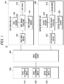
- FIG. 1 is a diagram illustrating a wiper system for a railway vehicle according to an embodiment of the present disclosure
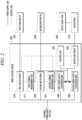
- FIG. 2 is a diagram illustrating a wiper control device according to an embodiment of the present disclosure
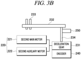
- FIGS. 3A and 3B are diagrams illustrating a wiper drive unit according to an embodiment of the present disclosure
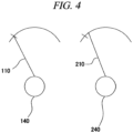
- FIG. 4 is a view illustrating a drive principle of the wiper system for a railway vehicle according to an embodiment of the present disclosure
- FIG. 5 is a diagram illustrating a wiper system for a railway vehicle according to another embodiment of the present disclosure
- FIG. 6 is a diagram illustrating a first wiper control device and a second wiper control device of a wiper system for a railway vehicle according to another embodiment of the present disclosure.
- an electric dual-mode wiper system 10 for a railway vehicle includes a first wiper drive unit 100, a second wiper drive unit 200, a first current measurement unit 311, a second current measurement unit 321, and a wiper control device 300.
- the first wiper drive unit 100 may include a first wiper 110 that is in close contact with an outer surface of glass of a railway vehicle to wipe off foreign matter adhering to the glass, a first drive motor 120 that drives the first wiper 110, a first linkage structure 130 that connects the first drive motor 120 to the first wiper 110, and a first encoder 140 that detects an operation state of the first linkage structure 130.
- the first drive motor 120 may rotate when receiving a power supply voltage from an external power supply and may transmit a rotational force to the first wiper 110 through the first linkage structure 130. In this case, the first wiper 110 may perform a reciprocating rotation.
- the second wiper drive unit 200 may include a second wiper 210 spaced apart from the first wiper 110 by a predetermined distance, a second drive motor 220 that drives the second wiper 210, a second linkage structure 230 that connects the second drive motor 220 to the second wiper 210, and a second encoder 240 that detects an operation state of the second linkage structure 230.
- the second drive motor 220 may rotate when receiving an external power supply voltage and may transmit a rotational force to the second wiper 210 through the second linkage structure 230. In this case, the second wiper 210 may perform a reciprocating rotation.
- the first drive motor 120 and the second drive motor 220 may be directly connected to the external power supply voltage, and a power supply voltage which is converted by power supply conversion units 340 and 350 for converting the power supply voltage may be applied to a first current measurement unit 311, a second current measurement unit 321, a water pump 410, and a control unit 330 which will be described below.
- the wiper control device 300 controls the first wiper drive unit 100 and the second wiper drive unit 200 according to a speed adjustment switching signal, a mode adjustment switching signal, and a water pump drive switching signal that are inputted from a wiper operation unit 500.
- the wiper control device 300 may include a first motor driver 310 that controls the first drive motor 120, a second motor driver 320 that controls the second drive motor 220, and the control unit 330 that controls the first motor driver 310 and the second motor driver 320.
- the control unit 330 may be a micro controller unit (MCU), and the first motor driver 310 and the second motor driver 320 may include at least one circuit element but are not limited thereto.
- the control unit 330 may control driving the first drive motor 120 through the first motor driver 310. In addition, the control unit 330 may control a drive speed of the first drive motor 120 through the first motor driver 310. Specifically, the control unit 330 may calculate (or receive) a target speed value of the first drive motor 120 as the speed adjustment switch 510 provided in a railway vehicle is turned on. The control unit 330 may drive the first drive motor 120 by providing a control power supply voltage to the first drive motor 120 based on the calculated (or received) target speed value.
- control unit 330 may control driving the second drive motor 220 through the second motor driver 320. In addition, the control unit 330 may control a drive speed of the second drive motor 220 through the second motor driver 320. Specifically, the control unit 330 may calculate (or receive) a target speed value of the second drive motor 220 as the speed adjustment switch 510 provided in the railway vehicle is turned on. The control unit 330 may drive the second drive motor 220 by providing the control power supply voltage to the second drive motor 220 based on the calculated (or received) target speed value.
- the first wiper 110 and the second wiper 210 may perform a reciprocating rotation at the same rotation speed to have the same angle.
- the first wiper 110 and the second wiper 210 have different loads due to a difference in window shape, a wind pressure, and precipitation, and thus, the first wiper 110 and the second wiper 210 may have different rotation speeds and angles.
- the wiper control device 300 may control synchronization operations of the first drive motor 120 and the second drive motor 220 based on information on operation states of the first linkage structure 130 and the second linkage structure 230 transmitted from the first encoder 140 and the second encoder 240, or information of current values of the first drive motor 120 and the second drive motor 220 transmitted from the first current measurement unit 311 and the second current measurement unit 321.
- the first current measurement unit 311 measures a current of the first drive motor 120 in real time. In addition, the first current measurement unit 311 may transmit information about the measured current of the first drive motor 120 to the control unit 330.
- the second current measurement unit 321 measures a current of the second drive motor 220 in real time.
- the second current measurement unit 321 may transmit information on the measured current of the second drive motor 220 to the control unit 330.
- the control unit 330 may switch a rotation direction of the first drive motor 120 to an opposite direction to move the first wiper 110 to an initial position.
- the wiper control device 300 may return the first wiper 110 by adjusting a speed of the first wiper 110 in a low-speed step.
- a current value of the first drive motor 120 measured by the first current measurement unit 311 is increased, and when a drive current value of the first drive motor 120 is measured to be greater than a threshold value (for example, a maximum drive current value), it is determined that an overcurrent is generated, and the rotation direction of the first drive motor 120 may be switched to the opposite direction.
- a threshold value for example, a maximum drive current value
- the wiper control device 300 reduces a speed of the second wiper 210 such that the time required for one reciprocation when the wipers 110 and 210 are in a normal state is the same as the time required for one reciprocating motion when the wipers 110 and 210 are in an abnormal state, and stops the second wiper 210 for a predetermined time at the initial position, and thereafter, when the first wiper 110 returns to an initial start point, the wiper control device 300 starts to operate the second wiper 210 such that the first wiper 110 and the second wiper 210 have the same rotation angle and speed, and thus, synchronous control may be performed.
- a load is applied to the second wiper 210.
- a current value of the second drive motor 220 is measured to be greater than or equal to the threshold value by the second current measurement unit 321, and the control unit 330 may switch a rotation direction of the second drive motor 220 to an opposite direction to move the second wiper 210 to an initial position.
- the wiper control device 300 may return the second wiper 210 by adjusting a speed of the second wiper 110 in a low-speed step.
- a load increases due to adhering of foreign matter to the second wiper 210
- a current value of the second drive motor 220 measured by the second current measurement unit 321 is increased, and when a drive current value of the second drive motor 220 is measured to be greater than a threshold value (for example, a maximum drive current value)
- a threshold value for example, a maximum drive current value
- the wiper control device 300 reduces a speed of the first wiper 110 such that the time required for one reciprocation when the wipers 110 and 210 are in a normal state is the same as the time required for one reciprocation when the wipers 110 and 210 are in an abnormal state, and stops the first wiper 110 for a predetermined time at the initial position, and thereafter, when the second wiper 210 returns to an initial start point, the wiper control device 300 starts to operate the first wiper 110 such that the first wiper 110 and the second wiper 210 have the same rotation angle and speed, and thus, synchronous control may be performed.
- control unit 330 may control drive speeds of the first drive motor 120 and the second drive motor 220 by supplying a pulse width modulation control signal to the first drive motor 120 and the second drive motor 220.
- the first linkage structure 130 may include a first deceleration gear 131 that is connected to the first drive motor 120 to change a direction of a rotational force of the first drive motor 120 and transmit the rotational force, and a four-section link 132 that transmits the rotational force of the first deceleration gear 131 to a first wiper connection rotation shaft 133.
- the first encoder 140 may be connected to the first deceleration gear 131 to detect a rotation state of the first deceleration gear 131, and according to this, the control unit 330 may manage a position and speed information of the first wiper 110 based on information transmitted from the first encoder 140.
- the second linkage structure 230 may include a second deceleration gear 231 that is connected to the second drive motor 220 to change a direction of a rotational force of the second drive motor 220 and transmit the rotational force, and a four-section link 232 that transmits the rotational force of the second deceleration gear 231 to a second wiper connection rotation shaft 233.
- the second encoder 240 may be connected to the second deceleration gear 231 to detect a rotation state of the second deceleration gear 231, and according to this, the control unit 330 may manage a position and speed information of the second wiper 210 based on information transmitted from the second encoder 240.
- control unit 330 may synchronously control the first drive motor 120 and the second drive motor 220 such that the first wiper 110 and the second wiper 210 have the same rotation speed and rotation angle, based on the rotation speed information and the rotation angle information of the first wiper 110 and the second wiper 210 transmitted from the first encoder 140 and the second encoder 240.
- the second wiper 210 in a state in which the first wiper 110 is in operation and the second wiper 210 is in a stopped state, in a case in which a drive command for the second wiper 210 is inputted, when the first wiper 110 returns to an initial start point, the second wiper 210 also starts to operate to cause a synchronous control to be performed such that the two wipers have the same rotation angle.
- rotation angles of the first wiper 110 and the second wiper 210 are measured by the first encoder 140 and the second encoder 240, and during one reciprocation, a speed of one of the first and second wipers 110 and 120 arriving at a point 1/10 from an initial start point is adjusted in proportion to a speed of the other wiper arriving there later such that the first and second wipers 110 and 120 arrive at the initial start point at the same time.
- the above-described one reciprocation means that a wiper starts to operate from an initial start point and returns to the initial start point.
- the control unit 330 may adjust a speed of a wiper by adjusting a power supply voltage supplied to a drive motor. In other words, when the power supply voltage supplied to the first drive motor 120 is reduced, the drive speed of the first drive motor 120 may be reduced, and when the power supply voltage supplied to the second drive motor 220 is reduced, the drive speed of the second drive motor 220 may be reduced.
- first wiper drive unit 100 may further include a first proximity sensor 150 for sensing a position of the first wiper 110
- the second wiper drive unit 200 may further include a second proximity sensor 250 for sensing a position of the second wiper 210.
- the first proximity sensor 150 may sense a nearest state of a marker arranged on an output shaft 134 of the first deceleration gear 131 to manage position information of the first wiper 110.
- the second proximity sensor 250 may sense a nearest state of a marker arranged on an output shaft 234 of the second deceleration gear 231 to manage position information of the second wiper 210.
- the markers may protrude outward from the output shafts but are not limited thereto.
- the electric dual-mode wiper system 10 may measure the rotation speeds of the first wiper 110 and the second wiper 210 through the first proximity sensor 150 and the second proximity sensor 250 and may synchronously control the first drive motor 120 and the second drive motor 220 based on the rotation speeds.
- the first and second encoders 140 and 240 and the first and second proximity sensors 150 and 250 have the same function, that is, a function to measure rotation speeds and rotation angles of the first and second wipers 110 and 210, and have a complementary configuration that may be complemented, when one component thereof is damaged or fails.
- the first drive motor 120 includes a first main motor 121 and a first auxiliary motor 122.
- the first wiper 110 is driven by the first main motor 121, and when the first main motor 121 is in an inoperable state due to a failure, the first auxiliary motor 122 is operated to operate the first wiper 110.
- the first main motor 121 and the first auxiliary motor 122 may be connected to the first deceleration gear 131 through a bevel gear.
- the second drive motor 220 may include a second main motor 221 and a second auxiliary motor 222.
- the second wiper 210 is driven by the second main motor 221, and when the second main motor 221 is in an inoperable state due to a failure, the second auxiliary motor 222 is operated to operate the second wiper 210.
- the second main motor 221 and the second auxiliary motor 222 may be connected to the second deceleration gear 231 through a bevel gear.
- the present disclosure is not limited thereto, and the first drive motor 120 may also be configured to include the first and second main motors 121 and 122, and the second drive motor 220 may also be configured with one motor.
- the electric dual-mode wiper system 10 may include a first washer liquid spraying module (not illustrated) that is coupled to the first wiper 110 and sprays a washer liquid, a second washer liquid spraying module (not illustrated) that is coupled to the second wiper 210 and sprays a washer liquid, a water pump 410 that supplies a washer liquid to the first washer liquid spraying module and the second washer liquid spraying module, and a washer liquid tank 420 filled with a washer liquid to be supplied to the water pump 410.
- a first washer liquid spraying module (not illustrated) that is coupled to the first wiper 110 and sprays a washer liquid
- a second washer liquid spraying module (not illustrated) that is coupled to the second wiper 210 and sprays a washer liquid
- a water pump 410 that supplies a washer liquid to the first washer liquid spraying module and the second washer liquid spraying module
- a washer liquid tank 420 filled with a washer liquid to be supplied to the water pump 410.
- the water pump 410 operates according to a water pump drive switch 530 to be described below to make the washer liquid filled in the washer liquid tank 420 be supplied to the first washer liquid spraying module and the second washer liquid spraying module, and thereby, the washer liquid may be sprayed onto a window of a railway vehicle.
- the electric dual-mode wiper system 10 may further include a wiper operation unit 500 connected to the wiper control device 300.
- the wiper operation unit 500 may include a speed adjustment switch 510 for adjusting speeds of the first wiper 110 and the second wiper 210, a mode adjustment switch 520 for adjusting drive modes of the first wiper 110 and the second wiper 210, and a water pump drive switch 530 for adjusting whether or not to drive the water pump 410.
- a washer liquid may be sprayed and the first and second wipers 110 and 210 may operate, and after the water pump drive switch 530 is pressed, the washer liquid may be sprayed and the first and second wipers 110 and 210 may stop after a reciprocating operation is performed three times.
- the speeds of the first and second wipers 110 and 210 may be adjusted to increase or decrease step by step.
- the first drive motor 120 or the second drive motor 220 may rotate in a reverse direction to return the first and second wipers 110 and 120 to initial positions thereof based on information on a rotation speed or a rotation angle of the first wiper 110 or the second wiper 210 measured in real time by the first encoder 140 or the second encoder 240, and may operate again.
- the mode adjustment switch 520 may be adjusted to selectively operate the first wiper 110 and the second wiper 210.
- the mode adjustment switch 520 may be positioned as the auxiliary wiper to operate the auxiliary wiper.
- the wiper control device 300 may further include a first power supply conversion unit 340 and a second power supply conversion unit 350 that convert an external power supply voltage.
- the first power supply conversion unit 340 and the second power supply conversion unit 350 may convert the external power supply voltage to 25 volts but are not limited thereto.
- the power supply voltage converted by the first power supply conversion unit 340 or the second power supply conversion unit 350 may be supplied to the control unit 330 and the water pump 410, and the external power supply voltage may be supplied to the first drive motor 120 and the second drive motor 220 without passing through the power supply conversion units 340 and 350.
- the electric dual-mode wiper system 10 includes two power supply conversion units, and when one power supply conversion unit fails, the power supply voltage may be continuously supplied through the other power supply conversion unit, and thereby, the wiper control device 300 may operate. For example, when the first power supply conversion unit 340 is in an abnormal state, the external power supply voltage may be converted by the second power supply conversion unit 350 to be supplied.
- the electric dual-mode wiper system 10 for a railway vehicle may include a first wiper control device 301 that controls a first wiper drive unit 100, and a second wiper control device 302 that controls a second wiper drive unit 200.
- the first wiper control device 301 may include a first motor driver 310 that controls a first drive motor 120, and a first control unit 331 that controls the first motor driver 310.
- the second wiper control device 302 may include a second motor driver 320 that controls a second drive motor 220, and a second control unit 332 that controls the second motor driver 320.
- the first control unit 331 may control a drive and a drive speed of the first drive motor 120 through the first motor driver 310. Specifically, the first control unit 331 may calculate (or receive) a target speed value of the first drive motor 120 as the speed adjustment switch 510 provided in a railway vehicle is turned on. The first control unit 331 may drive the first drive motor 120 by providing a control power supply voltage to the first drive motor 120 based on the calculated (or received) target speed value.
- the second control unit 332 may control a drive and a drive speed of the second drive motor 220 through the second motor driver 320. Specifically, the second control unit 332 may calculate (or receive) a target speed value of the second drive motor 220 as the speed adjustment switch 510 provided in a railway vehicle is turned on. The second control unit 332 may drive the second drive motor 220 by providing a control power supply voltage to the second drive motor 220 based on the calculated (or received) target speed value.
- first wiper control device 301 and the second wiper control device 302 may all perform a closed loop feedback control.
- the first wiper control device 301 may provide information on an operation state of the first linkage structure 130 which is transmitted from the first encoder 140 or the first proximity sensor 150 to the second wiper control device 302, and the second wiper control device 302 may provide information on an operation state of the second linkage structure 230 which is transmitted from the second encoder 240 or the second proximity sensor 250 to the first wiper control device 301.
- first wiper control device 301 may control the first drive motor 120 based on information transmitted from the second wiper control device 302, and the second wiper control device 302 may control the second drive motor 220 based on information transmitted from the first wiper control device 301.
- first wiper 110 is used as a main wiper and the second wiper 210 is used as an auxiliary wiper, even if the first wiper control device 301 for controlling the first wiper 110 fails, the second wiper 210 which is an auxiliary wiper is driven through the second wiper control device 302, and thus, there is an effect that stability is further increased.
- each of the first wiper control device 301 and the second wiper control device 302 is not configured to control only one wiper, and when one of the first and second wiper control device 301 and 302 fails, the other of the first and second wiper control devices 301 and 302 may also drive both the first and second wipers 110 and 120.
- an embodiment of the present disclosure may be implemented in the form of a recording medium including instructions executable by a computer, such as a program module executed by a computer.
- Computer-readable media may be any available media that can be accessed by a computer, and includes both volatile and nonvolatile media, removable and non-removable media.
- computer-readable media may include both computer storage media and communication media.
- the computer storage media includes both volatile and nonvolatile media, and removable and non-removable media implemented with any method or technology for storing information such as computer readable commands, data structures, program modules or other data.
- the communication media typically includes computer readable commands, data structures, program modules, other data of a modulated data signal such as a carrier wave, or other transmission mechanisms, and includes any information transmission media.
- first wiper drive unit 110 first wiper 120: first drive motor 121: first main motor 122: first auxiliary motor 130: first linkage structure 131: first deceleration gear 132: shaft four-section link 133: first wiper connection rotation 134: output shaft of first deceleration gear 140: first encoder 150: first proximity sensor 200: second wiper drive unit 210: second wiper 220: second drive motor 230: second linkage structure 240: second encoder 250: second proximity sensor 300: wiper control device 301: first wiper control device 302: second wiper control device 310: first motor driver 311: first current measurement unit 320: second motor driver 321: second current measurement unit 330: control unit 331: first control unit 332: second control unit 340: first power supply conversion unit 350: second power supply conversion unit 360: water pump driver 370: first current measurement unit 380: second current measurement unit 410: water pump 420: washer liquid tank 500: wiper operation unit 510: speed adjustment
Landscapes
- Engineering & Computer Science (AREA)
- Mechanical Engineering (AREA)
- Water Supply & Treatment (AREA)
- Electric Propulsion And Braking For Vehicles (AREA)
Claims (16)
- Elektrisches Dual-Mode-Scheibenwischersystem (10) für ein Schienenfahrzeug, umfassend:eine erste Scheibenwischerantriebseinheit (100), die einen ersten Scheibenwischer (110), einen ersten Antriebsmotor (120) zum Antreiben des ersten Scheibenwischers (110), eine erste Gestängestruktur (130) zum Verbinden des ersten Antriebsmotors (120) mit dem ersten Scheibenwischer (110) und einen ersten Codierer (140) zum Erfassen eines Betriebszustands der ersten Gestängestruktur (130) umfasst;eine zweite Scheibenwischerantriebseinheit (200), die einen zweiten Scheibenwischer (210), der so angeordnet ist, dass er von dem ersten Scheibenwischer (110) beabstandet ist, einen zweiten Antriebsmotor (220) zum Antreiben des zweiten Scheibenwischers (210), eine zweite Gestängestruktur (230) zum Verbinden des zweiten Antriebsmotors (220) mit dem zweiten Scheibenwischer (210) und einen zweiten Codierer (240) zum Erfassen eines Betriebszustands der zweiten Gestängestruktur (230) umfasst; undeine Scheibenwischersteuervorrichtung (300), die einen Synchronisationsbetrieb des ersten Antriebsmotors (120) und des zweiten Antriebsmotors (220) auf der Grundlage von Informationen über die Betriebszustände der ersten Gestängestruktur (130) und der zweiten Gestängestruktur (230) steuert, die von dem ersten Codierer (140) und dem zweiten Codierer (240) übertragen werden,dadurch gekennzeichnet, dass das elektrische Dual-Mode-Scheibenwischersystem (10) weiterhin umfasst:eine erste Strommesseinheit (311), die einen Strom des ersten Antriebsmotors (120) in Echtzeit misst; undeine zweite Strommesseinheit (321), die einen Strom des zweiten Antriebsmotors (220) in Echtzeit misst;wobei die Scheibenwischersteuervorrichtung (300) eine Drehrichtung des ersten Antriebsmotors (120) in eine entgegengesetzte Richtung schaltet und den ersten Scheibenwischer (110) in eine anfängliche Position desselben bewegt, wenn ein von der ersten Strommesseinheit (311) gemessener Stromwert des ersten Antriebsmotors (120) größer oder gleich einem Schwellenwert ist, und eine Drehrichtung des zweiten Antriebsmotors (220) in eine entgegengesetzte Richtung schaltet und den zweiten Scheibenwischer (210) in eine anfängliche Position desselben bewegt, wenn ein von der zweiten Strommesseinheit (321) gemessener Stromwert des zweiten Antriebsmotors (220) größer oder gleich einem Schwellenwert ist,wobei der erste Antriebsmotor (120) einen ersten Hauptmotor (121) und einen ersten Hilfsmotor (122) umfasst und den ersten Scheibenwischer (110) über den ersten Hilfsmotor (122) antreibt, wenn sich der erste Hauptmotor (121) in einem anomalen Zustand befindet.
- Elektrisches Dual-Mode-Scheibenwischersystem (10) nach Anspruch 1, wobei die Scheibenwischersteuervorrichtung (300) umfasst:einen ersten Motortreiber (310), der den ersten Antriebsmotor (120) so steuert, dass er in eine Vorwärts- oder Rückwärtsdrehung versetzt wird;einen zweiten Motortreiber (320), der den zweiten Antriebsmotor (220) so steuert, dass er in eine Vorwärts- oder Rückwärtsdrehung versetzt wird; undeine Steuereinheit (330), die den ersten Motortreiber (310) und den zweiten Motortreiber (320) steuert.
- Elektrisches Dual-Mode-Scheibenwischersystem (10) nach Anspruch 2,
wobei die Steuereinheit (330) den ersten Antriebsmotor (120) und den zweiten Antriebsmotor (220) synchron steuert, damit der erste Scheibenwischer (110) und der zweite Scheibenwischer (210) auf der Grundlage von Informationen, die von dem ersten Codierer (140) und dem zweiten Codierer (240) übertragen werden, die gleiche Drehgeschwindigkeit oder den gleichen Drehwinkel aufweisen. - Elektrisches Dual-Mode-Scheibenwischersystem (10) nach Anspruch 2,wobei die erste Scheibenwischerantriebseinheit (100) ferner einen ersten Näherungssensor (150) zum Erfassen einer Position des ersten Scheibenwischers (110) umfasst, undwobei die zweite Scheibenwischerantriebseinheit (200) ferner einen zweiten Näherungssensor (250) zum Erfassen einer Position des zweiten Scheibenwischers (210) umfasst.
- Elektrisches Dual-Mode-Scheibenwischersystem (10) nach Anspruch 4,
wobei die Steuereinheit (330) den ersten Antriebsmotor (120) und den zweiten Antriebsmotor (220) synchron steuert, damit der erste Scheibenwischer (110) und der zweite Scheibenwischer (210) die gleiche Drehgeschwindigkeit oder den gleichen Drehwinkel auf der Grundlage von Informationen aufweisen, die von dem ersten Codierer (140) und dem zweiten Codierer (240) übertragen werden, wenn sich der erste Codierer (140) und der zweite Codierer (240) in einem normalen Betrieb befinden, und den ersten Antriebsmotor (120) und den zweiten Antriebsmotor (220) synchron steuert, damit der erste Scheibenwischer (110) und der zweite Scheibenwischer (210) auf der Grundlage von Informationen, die von dem ersten Näherungssensor (150) und dem zweiten Näherungssensor (250) übertragen werden, die gleiche Drehgeschwindigkeit oder den gleichen Drehwinkel aufweisen, wenn sich der erste Codierer (140) und der zweite Codierer (240) in einem anomalen Betriebszustand befinden. - Elektrisches Dual-Mode-Scheibenwischersystem (10) nach Anspruch 1,
wobei die Scheibenwischersteuervorrichtung (300) die Drehrichtung des ersten Antriebsmotors (120) in die entgegengesetzte Richtung schaltet, um den ersten Scheibenwischer (110) in die anfängliche Position zu bewegen, und eine Geschwindigkeit des ersten Scheibenwischers (110) auf eine Stufe mit niedriger Geschwindigkeit einstellt, während sich der erste Scheibenwischer (110) in die anfängliche Position bewegt, und die Drehrichtung des zweiten Antriebsmotors (220) in die entgegengesetzte Richtung schaltet, um den zweiten Scheibenwischer (210) in die anfängliche Position zu bewegen, und eine Geschwindigkeit des zweiten Scheibenwischers (210) auf eine Stufe mit niedriger Geschwindigkeit einstellt, während sich der zweite Scheibenwischer (210) in die anfängliche Position bewegt. - Elektrisches Dual-Mode-Scheibenwischersystem (10) nach Anspruch 1,
wobei die Scheibenwischersteuervorrichtung (300) Geschwindigkeiten des ersten Scheibenwischers (110) und des zweiten Scheibenwischers (210) und Stoppzeiten in den anfänglichen Positionen so einstellt, dass Zeiten des ersten Scheibenwischers (110) und des zweiten Scheibenwischers (210), die für eine Hin- und Herbewegung erforderlich sind, wenn sich der erste Scheibenwischer (110) und der zweite Scheibenwischer (210) in einem normalen Zustand befinden, die gleichen sind wie Zeiten des ersten Scheibenwischers (110) und des zweiten Scheibenwischers (210), die für eine Hin- und Herbewegung erforderlich sind, wenn sich der erste Scheibenwischer (110) und der zweite Scheibenwischer (210) in einem anomalen Zustand befinden. - Elektrisches Dual-Mode-Scheibenwischersystem (10) nach Anspruch 1, das außerdem umfasst:ein erstes Waschflüssigkeitssprühmodul, das mit dem ersten Scheibenwischer (110) gekoppelt ist, um eine Waschflüssigkeit zu versprühen;ein zweites Waschflüssigkeitssprühmodul, das mit dem zweiten Scheibenwischer (210) gekoppelt ist, um eine Waschflüssigkeit zu versprühen;eine Wasserpumpe (410) zum Zuführen einer Waschflüssigkeit zu den ersten und zweiten Waschflüssigkeitssprühmodulen; undeinen Waschflüssigkeitstank (420), der mit einer der Wasserpumpe zugeführten Waschflüssigkeit gefüllt ist,wobei die Scheibenwischersteuervorrichtung (300) ferner einen Wasserpumpentreiber (360) zur Steuerung der Wasserpumpe (410) umfasst.
- Elektrisches Dual-Mode-Scheibenwischersystem (10) nach Anspruch 1,wobei die erste Gestängestruktur (130) ein erstes Verzögerungsgetriebe (131), das mit dem ersten Antriebsmotor (120) verbunden ist und eine Richtung einer Rotationskraft des ersten Antriebsmotors (120) ändert und die Rotationskraft überträgt, und eine vierteilige Verbindung (132) zum Übertragen einer Rotationskraft des ersten Verzögerungsgetriebes (131) auf eine erste Scheibenwischerverbindungsrotationswelle (133) umfasst, undwobei die zweite Gestängestruktur (230) ein zweites Verzögerungsgetriebe (231), das mit dem zweiten Antriebsmotor (220) verbunden ist und eine Richtung einer Rotationskraft des zweiten Antriebsmotors (220) ändert und die Rotationskraft überträgt, und eine vierteilige Verbindung (232) zum Übertragen einer Rotationskraft des zweiten Verzögerungsgetriebes (231) auf eine zweite Scheibenwischerverbindungsrotationswelle (233) umfasst.
- Elektrisches Dual-Mode-Scheibenwischersystem (10) nach Anspruch 1, das außerdem umfasst:eine Scheibenwischerbetätigungseinheit (500), die mit der Scheibenwischersteuervorrichtung (300) verbunden ist,wobei die Scheibenwischerbetätigungseinheit (500) umfasst:einen Geschwindigkeitseinstellschalter (510) zum Einstellen der Geschwindigkeiten des ersten Scheibenwischers (110) und des zweiten Scheibenwischers (210);einen Moduseinstellschalter (520) zum Einstellen der Betriebsarten des ersten Scheibenwischers (110) und des zweiten Scheibenwischers (210); undeinen Wasserpumpenantriebsschalter (530) zum Einstellen, ob eine Wasserpumpe (410) angetrieben werden soll oder nicht.
- Elektrisches Dual-Mode-Scheibenwischersystem (10) nach Anspruch 1, wobei die Scheibenwischersteuervorrichtung (300) ferner eine erste Stromversorgungsumwandlungseinheit (340) und eine zweite Stromversorgungsumwandlungseinheit (350) enthält, die eine externe Versorgungsspannung umwandeln, und die externe Versorgungsspannung durch die zweite Stromversorgungsumwandlungseinheit (350) umwandelt und die umgewandelte Spannung liefert, wenn die erste Stromversorgungsumwandlungseinheit (340) in einem anomalen Zustand ist.
- Elektrisches Dual-Modescheibenwischersystem (10) nach Anspruch 11, wobei der erste Antriebsmotor (120) und der zweite Antriebsmotor (220) die externe Versorgungsspannung direkt erhalten, ohne durch die erste Stromversorgungsumwandlungseinheit (340) oder die zweite Stromversorgungsumwandlungseinheit (350) zu laufen.
- Elektrisches Dual-Modescheibenwischersystem (10) nach Anspruch 2, wobei die Steuereinheit (330) den zweiten Scheibenwischer (210) zum Betrieb steuert, wenn der erste Scheibenwischer (110) zu einem anfänglichen Startpunkt zurückkehrt, in einem Fall, in dem der erste Scheibenwischer (110) in Betrieb ist und der zweite Scheibenwischer (210) in einem gestoppten Zustand ist.
- Elektrisches Dual-Mode-Scheibenwischersystem (10) nach Anspruch 2, wobei die Steuereinheit (330) Geschwindigkeiten des ersten Scheibenwischers (110) und des zweiten Scheibenwischers (210) durch den ersten Codierer (140) und den zweiten Codierer (240) misst und die Geschwindigkeit des ersten Scheibenwischers (110), der an einem Punkt 1/10 von einem anfänglichen Startpunkt ankommt, im Verhältnis zu der Geschwindigkeit des zweiten Scheibenwischers (210), der dort später als der erste Scheibenwischer (110) ankommt, so einstellt, dass der erste und der zweite Scheibenwischer (110, 210) während einer Hin- und Herbewegung zur gleichen Zeit am anfänglichen Startpunkt ankommen.
- Elektrisches Dual-Mode-Scheibenwischersystem (10) nach Anspruch 1,
wobei die Scheibenwischersteuervorrichtung (300) eine erste Scheibenwischersteuervorrichtung (301), die die erste Scheibenwischerantriebseinheit (100) steuert, und eine zweite Scheibenwischersteuervorrichtung (302), die die zweite Scheibenwischerantriebseinheit (200) steuert, umfasst. - Elektrisches Dual-Mode-Scheibenwischersystem (10) nach Anspruch 1,
wobei der zweite Antriebsmotor (220) einen zweiten Hauptmotor (221) und einen zweiten Hilfsmotor (222) umfasst und den zweiten Scheibenwischer (210) durch den zweiten Hilfsmotor (222) antreibt, wenn der zweite Hauptmotor (221) in einem anormalen Zustand ist.
Applications Claiming Priority (1)
| Application Number | Priority Date | Filing Date | Title |
|---|---|---|---|
| PCT/KR2020/007493 WO2021251517A1 (ko) | 2020-06-10 | 2020-06-10 | 철도차량용 전기식 이중화 와이퍼 시스템 |
Publications (4)
| Publication Number | Publication Date |
|---|---|
| EP3950439A1 EP3950439A1 (de) | 2022-02-09 |
| EP3950439A4 EP3950439A4 (de) | 2023-03-15 |
| EP3950439C0 EP3950439C0 (de) | 2024-08-07 |
| EP3950439B1 true EP3950439B1 (de) | 2024-08-07 |
Family
ID=78824380
Family Applications (1)
| Application Number | Title | Priority Date | Filing Date |
|---|---|---|---|
| EP20804418.0A Active EP3950439B1 (de) | 2020-06-10 | 2020-06-10 | Elektrisches doppelmodus-wischersystem für schienenfahrzeug |
Country Status (3)
| Country | Link |
|---|---|
| US (1) | US11945477B2 (de) |
| EP (1) | EP3950439B1 (de) |
| WO (1) | WO2021251517A1 (de) |
Families Citing this family (1)
| Publication number | Priority date | Publication date | Assignee | Title |
|---|---|---|---|---|
| CN116500915A (zh) * | 2022-12-29 | 2023-07-28 | 西安庆安电气控制有限责任公司 | 一种基于硬件电路的机载雨刷同步控制装置 |
Family Cites Families (9)
| Publication number | Priority date | Publication date | Assignee | Title |
|---|---|---|---|---|
| JPH0751408Y2 (ja) * | 1988-02-15 | 1995-11-22 | アラコ株式会社 | 複数モータ式ワイパー同期駆動装置 |
| JPH0751408A (ja) | 1993-08-19 | 1995-02-28 | Bridgestone Sports Co Ltd | ラケット |
| WO1998029285A1 (en) * | 1997-01-03 | 1998-07-09 | Mccord Winn Textron, Inc. | Windshield wiper system |
| KR20050006757A (ko) * | 2003-07-10 | 2005-01-17 | 현대자동차주식회사 | 우적 감응형 윈드 시일드 와이퍼 시스템 |
| CN102616209B (zh) * | 2012-04-12 | 2014-02-26 | 株洲联诚集团有限责任公司 | 一种轨道机车用双气动马达同步刮雨器 |
| KR101527683B1 (ko) | 2014-04-03 | 2015-06-17 | 주식회사 에스에이치에이치(Shh) | 철도차량의 와이퍼 응급 구동장치 |
| US11420594B2 (en) * | 2017-08-28 | 2022-08-23 | Rosemount Aerospace Inc. | Configurable variable sweep variable speed wiper system |
| KR102096987B1 (ko) * | 2018-11-15 | 2020-04-03 | 한국철도기술연구원 | 과부하 방지 기능을 갖는 철도차량용 전기식 와이퍼 시스템 |
| KR102096994B1 (ko) * | 2018-11-15 | 2020-04-03 | 한국철도기술연구원 | 철도차량용 전기식 이중화 와이퍼 시스템 |
-
2020
- 2020-06-10 WO PCT/KR2020/007493 patent/WO2021251517A1/ko not_active Ceased
- 2020-06-10 EP EP20804418.0A patent/EP3950439B1/de active Active
- 2020-11-10 US US17/093,979 patent/US11945477B2/en active Active
Also Published As
| Publication number | Publication date |
|---|---|
| EP3950439C0 (de) | 2024-08-07 |
| US20210387657A1 (en) | 2021-12-16 |
| EP3950439A4 (de) | 2023-03-15 |
| EP3950439A1 (de) | 2022-02-09 |
| US11945477B2 (en) | 2024-04-02 |
| WO2021251517A1 (ko) | 2021-12-16 |
Similar Documents
| Publication | Publication Date | Title |
|---|---|---|
| US11807196B2 (en) | Configurable variable sweep variable speed wiper system | |
| US7895702B2 (en) | Windshield wiper system with a self-locking device that is active when the wiper drive is in a non-operating state | |
| EP3950439B1 (de) | Elektrisches doppelmodus-wischersystem für schienenfahrzeug | |
| KR20030009499A (ko) | 2 개의 와이퍼를 포함하는 와이퍼 장치 | |
| US20110210210A1 (en) | Secure Monitoring and Control Device for Aircraft Piloting Actuator | |
| US20210046972A1 (en) | Steering device | |
| EP3766747B1 (de) | Dynamische wischersteuerung | |
| EP1752351B1 (de) | Elektrische Bremse und Bremsregelvorrichtung | |
| KR102096994B1 (ko) | 철도차량용 전기식 이중화 와이퍼 시스템 | |
| US20210323505A1 (en) | Smart wiper system | |
| KR102096987B1 (ko) | 과부하 방지 기능을 갖는 철도차량용 전기식 와이퍼 시스템 | |
| KR102042335B1 (ko) | 액추에이터모듈 | |
| CN118157424B (zh) | 一种无刷电机及其定位转向控制方法、高空作业车 | |
| CA2380425A1 (en) | Method for positioning a closing surface which is actuated by an external force | |
| US12129020B2 (en) | Aircraft electric taxi system design and operation | |
| CN114590334B (zh) | 一种四驱变形轮控制方法及系统 | |
| EP1069014B1 (de) | Wischermotor | |
| US20190337488A1 (en) | Windshield wiper system with sector gear | |
| JP6454132B2 (ja) | ワイパシステム | |
| US20180141520A1 (en) | Wiper system control device | |
| KR101859449B1 (ko) | 철도 차량용 와이퍼의 병렬구동 시스템 | |
| US7019477B2 (en) | Method for controlling a wiper motor | |
| CN104837712A (zh) | 一种保证转向横拉杆的计算机保护的助力转向控制方法 | |
| CN210554676U (zh) | 一种雨刮的调速控制系统 | |
| CN218949172U (zh) | 一种公交客车自动驾驶系统 |
Legal Events
| Date | Code | Title | Description |
|---|---|---|---|
| STAA | Information on the status of an ep patent application or granted ep patent |
Free format text: STATUS: UNKNOWN |
|
| STAA | Information on the status of an ep patent application or granted ep patent |
Free format text: STATUS: THE INTERNATIONAL PUBLICATION HAS BEEN MADE |
|
| PUAI | Public reference made under article 153(3) epc to a published international application that has entered the european phase |
Free format text: ORIGINAL CODE: 0009012 |
|
| STAA | Information on the status of an ep patent application or granted ep patent |
Free format text: STATUS: REQUEST FOR EXAMINATION WAS MADE |
|
| 17P | Request for examination filed |
Effective date: 20201120 |
|
| AK | Designated contracting states |
Kind code of ref document: A1 Designated state(s): AL AT BE BG CH CY CZ DE DK EE ES FI FR GB GR HR HU IE IS IT LI LT LU LV MC MK MT NL NO PL PT RO RS SE SI SK SM TR |
|
| A4 | Supplementary search report drawn up and despatched |
Effective date: 20230214 |
|
| RIC1 | Information provided on ipc code assigned before grant |
Ipc: B61D 25/00 20060101ALI20230208BHEP Ipc: B60S 1/50 20060101ALI20230208BHEP Ipc: B60S 1/48 20060101ALI20230208BHEP Ipc: B60S 1/08 20060101AFI20230208BHEP |
|
| DAV | Request for validation of the european patent (deleted) | ||
| DAX | Request for extension of the european patent (deleted) | ||
| GRAP | Despatch of communication of intention to grant a patent |
Free format text: ORIGINAL CODE: EPIDOSNIGR1 |
|
| STAA | Information on the status of an ep patent application or granted ep patent |
Free format text: STATUS: GRANT OF PATENT IS INTENDED |
|
| INTG | Intention to grant announced |
Effective date: 20240326 |
|
| GRAS | Grant fee paid |
Free format text: ORIGINAL CODE: EPIDOSNIGR3 |
|
| GRAA | (expected) grant |
Free format text: ORIGINAL CODE: 0009210 |
|
| STAA | Information on the status of an ep patent application or granted ep patent |
Free format text: STATUS: THE PATENT HAS BEEN GRANTED |
|
| AK | Designated contracting states |
Kind code of ref document: B1 Designated state(s): AL AT BE BG CH CY CZ DE DK EE ES FI FR GB GR HR HU IE IS IT LI LT LU LV MC MK MT NL NO PL PT RO RS SE SI SK SM TR |
|
| REG | Reference to a national code |
Ref country code: GB Ref legal event code: FG4D |
|
| REG | Reference to a national code |
Ref country code: CH Ref legal event code: EP |
|
| REG | Reference to a national code |
Ref country code: IE Ref legal event code: FG4D |
|
| REG | Reference to a national code |
Ref country code: DE Ref legal event code: R096 Ref document number: 602020035440 Country of ref document: DE |
|
| U01 | Request for unitary effect filed |
Effective date: 20240807 |
|
| U07 | Unitary effect registered |
Designated state(s): AT BE BG DE DK EE FI FR IT LT LU LV MT NL PT RO SE SI Effective date: 20240902 |
|
| PG25 | Lapsed in a contracting state [announced via postgrant information from national office to epo] |
Ref country code: NO Free format text: LAPSE BECAUSE OF FAILURE TO SUBMIT A TRANSLATION OF THE DESCRIPTION OR TO PAY THE FEE WITHIN THE PRESCRIBED TIME-LIMIT Effective date: 20241107 |
|
| PG25 | Lapsed in a contracting state [announced via postgrant information from national office to epo] |
Ref country code: PL Free format text: LAPSE BECAUSE OF FAILURE TO SUBMIT A TRANSLATION OF THE DESCRIPTION OR TO PAY THE FEE WITHIN THE PRESCRIBED TIME-LIMIT Effective date: 20240807 Ref country code: GR Free format text: LAPSE BECAUSE OF FAILURE TO SUBMIT A TRANSLATION OF THE DESCRIPTION OR TO PAY THE FEE WITHIN THE PRESCRIBED TIME-LIMIT Effective date: 20241108 |
|
| PG25 | Lapsed in a contracting state [announced via postgrant information from national office to epo] |
Ref country code: IS Free format text: LAPSE BECAUSE OF FAILURE TO SUBMIT A TRANSLATION OF THE DESCRIPTION OR TO PAY THE FEE WITHIN THE PRESCRIBED TIME-LIMIT Effective date: 20241207 |
|
| PG25 | Lapsed in a contracting state [announced via postgrant information from national office to epo] |
Ref country code: HR Free format text: LAPSE BECAUSE OF FAILURE TO SUBMIT A TRANSLATION OF THE DESCRIPTION OR TO PAY THE FEE WITHIN THE PRESCRIBED TIME-LIMIT Effective date: 20240807 |
|
| PG25 | Lapsed in a contracting state [announced via postgrant information from national office to epo] |
Ref country code: RS Free format text: LAPSE BECAUSE OF FAILURE TO SUBMIT A TRANSLATION OF THE DESCRIPTION OR TO PAY THE FEE WITHIN THE PRESCRIBED TIME-LIMIT Effective date: 20241107 Ref country code: ES Free format text: LAPSE BECAUSE OF FAILURE TO SUBMIT A TRANSLATION OF THE DESCRIPTION OR TO PAY THE FEE WITHIN THE PRESCRIBED TIME-LIMIT Effective date: 20240807 |
|
| PG25 | Lapsed in a contracting state [announced via postgrant information from national office to epo] |
Ref country code: RS Free format text: LAPSE BECAUSE OF FAILURE TO SUBMIT A TRANSLATION OF THE DESCRIPTION OR TO PAY THE FEE WITHIN THE PRESCRIBED TIME-LIMIT Effective date: 20241107 Ref country code: PL Free format text: LAPSE BECAUSE OF FAILURE TO SUBMIT A TRANSLATION OF THE DESCRIPTION OR TO PAY THE FEE WITHIN THE PRESCRIBED TIME-LIMIT Effective date: 20240807 Ref country code: NO Free format text: LAPSE BECAUSE OF FAILURE TO SUBMIT A TRANSLATION OF THE DESCRIPTION OR TO PAY THE FEE WITHIN THE PRESCRIBED TIME-LIMIT Effective date: 20241107 Ref country code: IS Free format text: LAPSE BECAUSE OF FAILURE TO SUBMIT A TRANSLATION OF THE DESCRIPTION OR TO PAY THE FEE WITHIN THE PRESCRIBED TIME-LIMIT Effective date: 20241207 Ref country code: HR Free format text: LAPSE BECAUSE OF FAILURE TO SUBMIT A TRANSLATION OF THE DESCRIPTION OR TO PAY THE FEE WITHIN THE PRESCRIBED TIME-LIMIT Effective date: 20240807 Ref country code: GR Free format text: LAPSE BECAUSE OF FAILURE TO SUBMIT A TRANSLATION OF THE DESCRIPTION OR TO PAY THE FEE WITHIN THE PRESCRIBED TIME-LIMIT Effective date: 20241108 Ref country code: ES Free format text: LAPSE BECAUSE OF FAILURE TO SUBMIT A TRANSLATION OF THE DESCRIPTION OR TO PAY THE FEE WITHIN THE PRESCRIBED TIME-LIMIT Effective date: 20240807 |
|
| PG25 | Lapsed in a contracting state [announced via postgrant information from national office to epo] |
Ref country code: SM Free format text: LAPSE BECAUSE OF FAILURE TO SUBMIT A TRANSLATION OF THE DESCRIPTION OR TO PAY THE FEE WITHIN THE PRESCRIBED TIME-LIMIT Effective date: 20240807 |
|
| PG25 | Lapsed in a contracting state [announced via postgrant information from national office to epo] |
Ref country code: CZ Free format text: LAPSE BECAUSE OF FAILURE TO SUBMIT A TRANSLATION OF THE DESCRIPTION OR TO PAY THE FEE WITHIN THE PRESCRIBED TIME-LIMIT Effective date: 20240807 |
|
| PG25 | Lapsed in a contracting state [announced via postgrant information from national office to epo] |
Ref country code: SK Free format text: LAPSE BECAUSE OF FAILURE TO SUBMIT A TRANSLATION OF THE DESCRIPTION OR TO PAY THE FEE WITHIN THE PRESCRIBED TIME-LIMIT Effective date: 20240807 |
|
| PLBE | No opposition filed within time limit |
Free format text: ORIGINAL CODE: 0009261 |
|
| STAA | Information on the status of an ep patent application or granted ep patent |
Free format text: STATUS: NO OPPOSITION FILED WITHIN TIME LIMIT |
|
| U20 | Renewal fee for the european patent with unitary effect paid |
Year of fee payment: 6 Effective date: 20250509 |
|
| 26N | No opposition filed |
Effective date: 20250508 |