EP3950438B1 - Deflector with spring element - Google Patents
Deflector with spring element Download PDFInfo
- Publication number
- EP3950438B1 EP3950438B1 EP21189161.9A EP21189161A EP3950438B1 EP 3950438 B1 EP3950438 B1 EP 3950438B1 EP 21189161 A EP21189161 A EP 21189161A EP 3950438 B1 EP3950438 B1 EP 3950438B1
- Authority
- EP
- European Patent Office
- Prior art keywords
- engagement
- deflector
- receptacle
- metal body
- spring element
- Prior art date
- Legal status (The legal status is an assumption and is not a legal conclusion. Google has not performed a legal analysis and makes no representation as to the accuracy of the status listed.)
- Active
Links
- 239000002184 metal Substances 0.000 claims description 92
- 238000005096 rolling process Methods 0.000 claims description 12
- 229920003023 plastic Polymers 0.000 claims description 7
- 239000004033 plastic Substances 0.000 claims description 7
- 239000000463 material Substances 0.000 claims description 3
- 238000004519 manufacturing process Methods 0.000 description 13
- 230000000284 resting effect Effects 0.000 description 9
- 230000007547 defect Effects 0.000 description 4
- 238000011161 development Methods 0.000 description 3
- 230000018109 developmental process Effects 0.000 description 3
- 238000005253 cladding Methods 0.000 description 2
- 230000001419 dependent effect Effects 0.000 description 2
- 230000036316 preload Effects 0.000 description 2
- 238000005299 abrasion Methods 0.000 description 1
- 238000005452 bending Methods 0.000 description 1
- 238000006073 displacement reaction Methods 0.000 description 1
- 230000000694 effects Effects 0.000 description 1
- 230000005284 excitation Effects 0.000 description 1
- 238000000034 method Methods 0.000 description 1
- 230000003362 replicative effect Effects 0.000 description 1
Images


Classifications
-
- B—PERFORMING OPERATIONS; TRANSPORTING
- B60—VEHICLES IN GENERAL
- B60R—VEHICLES, VEHICLE FITTINGS, OR VEHICLE PARTS, NOT OTHERWISE PROVIDED FOR
- B60R22/00—Safety belts or body harnesses in vehicles
- B60R22/34—Belt retractors, e.g. reels
-
- B—PERFORMING OPERATIONS; TRANSPORTING
- B60—VEHICLES IN GENERAL
- B60R—VEHICLES, VEHICLE FITTINGS, OR VEHICLE PARTS, NOT OTHERWISE PROVIDED FOR
- B60R22/00—Safety belts or body harnesses in vehicles
- B60R22/18—Anchoring devices
-
- B—PERFORMING OPERATIONS; TRANSPORTING
- B60—VEHICLES IN GENERAL
- B60R—VEHICLES, VEHICLE FITTINGS, OR VEHICLE PARTS, NOT OTHERWISE PROVIDED FOR
- B60R22/00—Safety belts or body harnesses in vehicles
- B60R22/18—Anchoring devices
- B60R2022/1812—Connections between seat belt and buckle tongue
-
- B—PERFORMING OPERATIONS; TRANSPORTING
- B60—VEHICLES IN GENERAL
- B60R—VEHICLES, VEHICLE FITTINGS, OR VEHICLE PARTS, NOT OTHERWISE PROVIDED FOR
- B60R22/00—Safety belts or body harnesses in vehicles
- B60R22/18—Anchoring devices
- B60R2022/1818—Belt guides
Definitions
- the present invention relates to a deflector for guiding a webbing in a vehicle, at least comprising a metal body with a fastening opening that can be attached to the vehicle and with a belt slot, and a plastic fitting piece connected to the metal body, the metal body having a receptacle and a fitting on the fitting piece an engagement section corresponding to the receptacle is formed, so that the engagement section engages in the receptacle, and wherein the receptacle has a receptacle inner surface facing the engagement section and the engagement section has an engagement surface facing the receptacle.
- Such deflectors are usually used in a vehicle to guide a belt strap, which is held in at least three places in the vehicle.
- the webbing is placed around the body of a vehicle occupant so that the body is restrained by the webbing when the vehicle brakes or otherwise moves relative to the vehicle.
- the webbing is, among other things, stretched by the deflector and held in a predetermined position, so that the webbing restrains the body in several different areas when it is put on.
- a generic deflector is attached to the vehicle and provides a belt guide slot for guiding the webbing, which completely encloses the webbing or at least surrounds it so that it cannot be lost.
- the belt strap is moved along the belt guide slot, for example when it is put on by the vehicle occupant or during a braking process, so that the belt strap rubs against the deflector, especially in the area of the belt slot.
- the diverter In order to provide a sufficient restraint effect, the diverter must not fail within the expected forces. For this reason, a metal body is usually used, which has at least one fastening opening for attachment to the vehicle and at the same time provides the belt slot. To reduce weight and for aesthetic reasons, the diverter often has a plastic adapter connected to the metal body.
- the metal body When manufacturing the metal body, higher tolerances are applied for manufacturing reasons than for the plastic fitting. As a result, the metal part is not always made to fit precisely, so that defects can occur during assembly to the diverter and rattling noises between the fitting piece and the metal body during operation of the diverter.
- a diverter with the aforementioned features, for example, is out DE 10 2004 050 154 B3 known.
- An engagement section of the fitting piece engages in the belt slot of the metal body, so that a positive connection is created in this area between the metal body and the fitting piece.
- the diverter is attached to the vehicle with a mounting opening.
- the fitting piece has at least one molded spring arm on the back facing the vehicle, which is supported against the vehicle, so that vibrations generated during operation do not cause rattling noises.
- Another diverter is also missing EP 2 639 118 A1 known.
- the disadvantage of deflectors made of two parts from a metal body and the fitting piece is that when the belt strap resting on the belt guide slot slides or when the belt is in operation Vibrations occurring in the vehicle cause rattling noises between the fitting and the metal body. Rattling noises can occur, particularly in areas in which a positive connection is formed, for example through an engagement section that engages in the metal body. Furthermore, during the production of the fitting piece or the metal body, engagement surfaces that do not exactly match each other can occur due to manufacturing reasons.
- the metal body which is in particular a metal stamped part, is often bent, rolled or additionally punched during further processing. The metal body usually has higher tolerance limits during production. Therefore, the fitting piece and the metal body, in the area in which the positive fit is to be formed, often do not lie against each other as desired and rattling noises occur, especially between the two components.
- the object of the present invention is to eliminate the disadvantages described with reference to the prior art and to provide an improved deflector for guiding a webbing in a vehicle.
- the task is solved in particular by a deflector with the features mentioned at the outset, the engagement section having at least one spring element resting on the receiving inner surface.
- the deflector is fixed to the vehicle using a fastener that can be inserted into the fastening opening of the metal body.
- a webbing can be arranged in the belt slot so that the webbing is held in the belt slot.
- the engagement section of the fitting piece engages in the receptacle of the metal body, so that both parts are connected to one another in a form-fitting manner and form the diverter.
- the receptacle of the metal body also has an inner receptacle surface which replicates the contour of an engagement section of the fitting piece. An engagement surface of the engagement portion is therefore arranged in the receptacle and can be applied to the receptacle inner surface.
- the engagement surface rests at least partially, most preferably completely, on the receiving inner surface.
- a positive connection is created between the metal body and the fitting piece.
- Further connections can be formed between the metal body and the fitting piece, in particular by attaching the deflector to the vehicle.
- the engagement section has at least one spring element which rests on the receiving inner surface.
- the at least one spring element is under tension and presses against the receiving inner surface. Consequently, a biasing force is exerted by the fitting piece onto the metal body in the area of the receptacle by the at least one spring element.
- manufacturing-related surface defects in the area of the receiving inner surface can be compensated for by the at least one spring element, with the at least one spring element resting on the receiving inner surface even if there is play between the metal body and the fitting piece. Consequently, the spring elements help to compensate for manufacturing tolerances on the metal body.
- the at least one spring element can advantageously prevent defects in the area of the receptacle during assembly to the deflector. If vibrations occur during driving or if the belt strap slides in the belt slot in the area of the mount, Relative movement between the two components of the deflector, a rattling noise is additionally prevented or an excited vibration is dampened by the at least one spring element.
- the at least one spring element can also prevent rattling noise in other areas in contact between the metal body and the fitting.
- the fitting piece can have further cladding contours, so that the metal body is not visible when the deflector is installed in the vehicle.
- the upper section is preferably at least partially embedded in the fastening opening of the metal body, wherein the fastening means with which the deflector can be attached to the vehicle can preferably be passed through the fitting piece and can rest on the fitting piece.
- the at least one spring element resting on the receiving inner surface can be, for example, a resilient section of the engagement section, which protrudes or protrudes from the engagement section or the engagement surface, particularly in the unassembled state of the deflector.
- the spring element is preferably made of the same material as the fitting piece.
- the at least one spring element is also made of plastic and has a certain flexibility.
- the at least one spring element can be formed, attached or placed on the engagement section so that it presses against the fitting piece in the pre-assembled state of the deflector. In this way, the at least one spring element can prevent rattling noises in the deflector, compensate for manufacturing-related errors and avoid defects during assembly to the deflector, in particular by connecting the metal body to the fitting piece.
- the at least one spring element is formed in one piece with the fitting piece.
- the at least one spring element can be formed, for example, by a protruding section on the fitting piece itself.
- the at least one spring element is flexible and protrudes from the fitting piece in the unassembled state of the deflector.
- additional assembly or manufacturing steps can advantageously be dispensed with.
- the position of the at least one spring element on the engagement section can advantageously be specified.
- the fitting piece has at least two spring elements offset along the belt slot, so that the fitting piece can provide a spring force on the inner surface of the receiving surface at least at two offset locations.
- the particularly elongated belt slot which is shaped to fit the webbing, is aligned parallel to the receptacle of the fitting piece, which is preferably also elongated.
- a fitting piece that has at least two spring elements can advantageously prevent one-sided loading or relative movement between the fitting piece and the metal body.
- rattling noise can be better prevented in the area of the holder, local production errors can be compensated for by the at least two spring elements and overall higher tolerance limits can be set.
- the offset arrangement of the at least two spring elements makes it possible to prevent rattling noises and to compensate for them Production errors are advantageously uniform and in different areas of the metal body.
- the engagement surface has at least one opening and the at least one spring element is at least partially arranged in the opening.
- the engagement surface has an opening for each spring element.
- the arrangement of the at least one spring element in the at least one opening advantageously enables the at least one spring element not to protrude when resting on the receiving inner surface of the engagement surface, but rather to be aligned with the engagement surface in the area of the opening with a region resting on the receiving inner surface. In this way, it is advantageously possible for the receiving inner surface to rest against the engagement surface, with a spring force acting on the receiving inner surface being provided at the same time by the at least one spring element.
- the at least one spring element can be deflected in the direction of the receiving inner surface and can be deflected in the direction of the at least one opening.
- the at least one spring element resting on the receiving inner surface can advantageously be moved within the opening. In this way, the at least one spring element can particularly efficiently prevent rattling noises or compensate for unevenness in the inner surface of the receiving surface as a result of production errors.
- At least one deflectable and deflectable spring element is therefore flexible and advantageous Contact of the at least one spring element on the receiving inner surface of the metal body can be effected.
- a surface of the metal body facing away from the receiving inner surface forms a belt support surface delimiting the belt slot.
- the webbing can be guided through the particularly stable metal body.
- the guidance can be prevented by the at least one spring element, which is arranged in particular on the opposite side of the belt support surface, advantageously close to the origin of a rattling noise, in particular caused by the belt strap sliding on the belt slot. The vibrations excited by sliding can thus be dampened particularly efficiently and effectively by the at least one spring element.
- At least two engagement ribs are formed by the engagement surface, the at least two engagement ribs replicating a contour of the receiving inner surface, so that the at least two engagement ribs are applied to the receiving inner surface.
- the at least two engagement ribs are preferably arranged distributed, in particular regularly distributed, over the engagement surface.
- the at least two engagement ribs are preferably not arranged directly in the area of the at least one spring element, but are offset along the belt slot. In this way, a lateral displacement of the metal body relative to the fitting piece can advantageously be prevented, with the at least one spring element striking laterally against one of the at least two projecting engagement ribs.
- the receiving inner surface can advantageously rest on the at least two engagement ribs.
- the at least two engagement ribs can advantageously ensure that the metal body rests against the fitting piece in the area of the receptacle. Furthermore, a maximum deflection of the at least one spring element in the direction of the engagement section can be specified by the at least two engagement ribs, since the receiving inner surface in the area of the at least two engagement ribs It comes into contact with the engagement ribs that bind the engagement surface. For assembly purposes of the deflector, it is possible to deflect the at least one spring element via the projecting engagement ribs in the direction of the engagement section. If the at least one spring element is arranged in an opening, it is also possible for assembly purposes for the at least one spring element to be deflected beyond the opening into an inner region of the opening. The at least two engagement ribs can thus advantageously specify the area in which the metal body and the fitting piece rest in the area of the receptacle.
- the receptacle is formed by a rolling section extending in the direction of the belt slot.
- the metal body is preferably a metal stamping part
- a receptacle can advantageously be formed by bending or rolling a region of the metal stamping part.
- the engagement section of the fitting piece is designed to fit the rolling section extending in the direction of the belt slot. In this way, a rotation lock of the metal body to the fitting piece can advantageously be provided.
- a positive connection can advantageously be formed by a rolling section.
- the belt support surface can advantageously be formed by a surface of the rolling section facing away from the receiving inner surface.
- the maximum deflection of the at least one spring element is predetermined by the engagement surface and/or by the engagement ribs.
- the receiving inner surface preferably comes into at least partial contact with the engagement surface or one or more of the at least two engagement ribs forming the engagement surface. If there is a relative movement between the engagement surface and the receiving inner surface, the at least one spring element can, if desired, continue to cause tension by resting on the receiving inner surface between the metal body and the fitting piece.
- a maximum Deflection of the spring element in the direction of the engagement surface and thus the maximum acting spring force of the at least one spring element can advantageously be specified by the design of the engagement ribs or the engagement surface.
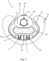
- the deflector 1 shown in the figures comprises a metal body 2 with a fastening opening 3 and a belt slot 4 as well as a fitting piece 5 connected to the metal body 2.
- the metal body 2 designed as a metal stamped part has a receptacle 6 with a receiving inner surface 8.
- the recording 6 is formed by a rolling section 15.
- An engagement section 7 of the fitting piece 5 has an engagement surface 9, wherein the engagement section 7 and the engagement surface 9 are designed corresponding to the receptacle 6 and the receptacle inner surface 8, so that the engagement section 7 can be arranged in the receptacle 6 and the fitting piece 5 with it the metal body 2 can be connected.
- Two openings 11 are formed on the engagement surface 9, in which two spring elements 10 formed integrally with the fitting piece 5 are arranged.
- the spring elements 10 rest against the receiving inner surface 8.
- a belt support surface 13 is formed by the surface 12 of the metal body 2.
- the engagement surface 9 has five engagement ribs 14, which are also designed corresponding to the receptacle 6, so that the five engagement ribs 14 rest on the receptacle inner surface 8.
- the metal body 2 also has a clip projection 23 above the fastening opening 3.
- the fitting piece 5 is formed by an upper section 18 and a lower section 19.
- the upper section 18 is recessed corresponding to the fastening opening 3 of the metal body 2, so that a fastening means can be guided through the fitting piece 5.
- the upper section 18 has a belt section 20 which engages in the belt slot 4 of the metal body 2.
- the upper section 18 of the fitting piece 5 is connected to the lower sections 19 via two connecting arms 17, each arranged laterally next to the attachment of the simulated fastening opening 3.
- the lower section 19 has the engagement section 7 with the spring arms 10 and the engagement ribs 14.
- a cladding contour 21 is additionally formed on the fitting piece 5, extending laterally from the lower section 19.
- the fitting piece 5 has a clip hook 16, which engages behind the clip projection 23 of the metal body 2 when the deflector 1 is installed. Furthermore, the fitting piece 5 has three support elements 24 on the back and three further clip hooks 22 directed in the direction of the fastening opening 3.
- the fitting piece 5 is attached to the metal body 2 via the clip hook 16, which engages behind the clip projection 23 of the metal body 2 above the fastening opening 3. Furthermore, the three further clip hooks 22 of the fitting piece 5 engage behind the metal body 2 in the area of the fastening opening 3.
- the three further clip hooks 22 are supported laterally from the inside against the fastening opening 3 of the metal body 2 and engage behind the metal body 2 offset over the circumference.
- the further clip hooks 22 are arranged in a regularly distributed manner over the circumference of the fastening opening 3.
- the three support elements 24 of the fitting piece 5 arranged on the rear are supported against a part of the vehicle and tension the deflector 1 against the part of the vehicle in addition to a fastening means that can be inserted into the fastening opening 3.
- the three support elements 24 are arranged offset from the other clip hooks 22 and are evenly distributed over the circumference of the fastening opening 3, which results in an advantageously uniform connection or support of the deflector 2.
- the Indian Figure 1 metal body 2 shown forms together with that in the Figure 2 Fitting piece 5 shown in Figure 3 shown deflector 1.
- the metal body 2 and the fitting piece 5 lie against each other in several areas, as shown in Figure 6 sectional view shown Figure 4 is removable.
- the fitting piece 5 engages with the belt section 20 in the belt slot 4.
- the fitting piece 5 engages in the metal body 2 in the area of the fastening opening 3, with the three further clip hooks 22 of the fitting piece 5 engaging in the fastening opening 3 of the metal body 2.
- the additional connection via the clip hook 16 on the clip projection 23 additionally holds the fitting piece 5 and the metal body 2 together.
- the connection of the metal body 2 and the fitting piece 5 to the deflector 1 also takes place via the engagement of the engagement section 7 in the receptacle 6.
- the engagement surface 9 has the five protruding engagement ribs 14, so that the engagement ribs 14 on the receptacle inner surface 8 of the receptacle 6
- Metal body 2 abut.
- the receptacle 6 is formed by a rolling section 15 of the metal body.
- the metal body 2 designed as a metal stamped part can be bent or rolled during its production, so that the receptacle 6 is curved inwards with the inner receptacle surface 8.
- Surface 12 of the metal body 2 in the area of the belt slot 4 provides a belt support surface 13.
- the surface 12 or the belt support surface 13 limits the belt slot 4 in one direction.
- the fitting piece 5 with the belt section 20 also engages in the belt slot 4 of the metal body 2 in the area of the belt support surface 13, so that a belt strap can advantageously slide along the fitting piece 5 and abrasion on the sharp edges of the belt slot 4 is avoided can be.
- the two spring elements protruding from the engagement surface 9 or the engagement ribs 14 are according to Figure 7 each arranged in an opening 11. If the fitting piece 5 is connected to the metal body 2 to form the deflector 1, the spring elements 10 press against the inner surface 8 of the receptacle 6 and can advantageously compensate for unevenness or an offset of the rolling section 15 of the metal body 2 and prevent tilting during assembly. Like in particular Figure 6 can be seen, the spring elements 10 are in contact with the receiving inner surface 8. The receiving inner surface 8 also rests on the five engagement ribs 14 that reproduce the contour of the receiving inner surface 8. The spring elements 10 are aligned, as in particular in Figure 6 can be seen, with the engagement ribs 14, which form the engagement surface 9 in sections. In this case, the spring elements 10 of the deflector 1 are deflected maximally in the direction of the interior of the engagement section 7, with the spring elements 10 being partly arranged in the corresponding opening 11.
- the two offset spring elements 10 can prevent the metal body 2 and the fitting piece 5 from striking or moving apart in an uncontrolled manner on one side. For example, by moving apart the metal body 2 and the fitting piece 5, on the in Figure 2 right side, the receiving inner surface 8 of the engagement ribs 14, the right spring element 10 can deflect accordingly and continue to rest on the receiving inner surface 8, so that a clamping force is still provided. The same applies if the receptacle 6 formed by the rolling section 15 has an irregularly shaped inner receptacle surface 8.
Description
Die vorliegende Erfindung betrifft einen Umlenker zur Führung eines Gurtbandes in einem Fahrzeug, zumindest aufweisend einen Metallkörper mit einer am Fahrzeug anbringbaren Befestigungsöffnung und mit einem Gurtschlitz, und ein mit dem Metallkörper verbundenes Passstück aus Kunststoff, wobei der Metallkörper eine Aufnahme aufweist und auf dem Passstück ein zu der Aufnahme korrespondierender Eingriffsabschnitt ausgebildet ist, sodass der Eingriffsabschnitt in die Aufnahme eingreift, und wobei die Aufnahme eine dem Eingriffsabschnitt zugewandte Aufnahmeinnenfläche aufweist und der Eingriffsabschnitt eine der Aufnahme zugewandte Eingriffsoberfläche aufweist.The present invention relates to a deflector for guiding a webbing in a vehicle, at least comprising a metal body with a fastening opening that can be attached to the vehicle and with a belt slot, and a plastic fitting piece connected to the metal body, the metal body having a receptacle and a fitting on the fitting piece an engagement section corresponding to the receptacle is formed, so that the engagement section engages in the receptacle, and wherein the receptacle has a receptacle inner surface facing the engagement section and the engagement section has an engagement surface facing the receptacle.
Üblicherweise werden solche Umlenker in einem Fahrzeug zur Führung eines Gurtbandes verwendet, welches an mindestens drei Stellen im Fahrzeug gehalten wird. Das Gurtband wird um den Körper eines Fahrzeuginsassen gelegt, sodass der Körper bei einer Bremsung des Fahrzeugs oder sonstigen Bewegung relativ zum Fahrzeug vom Gurtband zurückgehaltengehalten wird. Dabei wird das Gurtband unter Anderem von dem Umlenker aufgespannt und in einer vorgegebenen Position gehalten, sodass das Gurtband in einem angelegten Zustand den Körper in mehreren verschiedenen Bereichen zurückhält.Such deflectors are usually used in a vehicle to guide a belt strap, which is held in at least three places in the vehicle. The webbing is placed around the body of a vehicle occupant so that the body is restrained by the webbing when the vehicle brakes or otherwise moves relative to the vehicle. The webbing is, among other things, stretched by the deflector and held in a predetermined position, so that the webbing restrains the body in several different areas when it is put on.
Ein gattungsgemäßer Umlenker ist dabei am Fahrzeug befestigt und stellt zur Führung des Gurtbandes einen Gurtführungsschlitz bereit, welcher das Gurtband vollständig umschließt oder zumindest verliersicher umgibt. Dabei wird das Gurtband beispielsweise bei einem Anlegen durch den Fahrzeuginsassen oder bei einem Bremsvorgang entlang des Gurtführungsschlitzes bewegt, sodass es zu einer Reibung des Gurtbandes am Umlenker, insbesondere im Bereich des Gurtschlitzes, kommt. Um eine ausreichende Rückhaltewirkung bereitzustellen, darf der Umlenker im Rahmen der zu erwartenden Kräfte nicht versagen. Aus diesem Grund wird meist ein Metallkörper verwendet, welcher zumindest eine Befestigungsöffnung zur Anbringung an dem Fahrzeug aufweist und gleichzeitig den Gurtschlitz bereitstellt. Zur Gewichtsreduktion und aus ästhetischen Gründen, weist der Umlenker häufig ein mit dem Metallkörper verbundenes Passstück (englisch: adapter) aus Kunststoff auf. Bei der Fertigung des Metallkörpers werden herstellungsbedingt höhere Toleranzen angesetzt als bei dem Passstück aus Kunststoff. Folglich ist das Metallteil nicht immer passgenau gefertigt, sodass es bei der Montage zu dem Umlenker zu Defekten kommen kann und im Betrieb des Umlenkers zu Klappergeräuschen zwischen dem Passstück und dem Metallkörper.A generic deflector is attached to the vehicle and provides a belt guide slot for guiding the webbing, which completely encloses the webbing or at least surrounds it so that it cannot be lost. The belt strap is moved along the belt guide slot, for example when it is put on by the vehicle occupant or during a braking process, so that the belt strap rubs against the deflector, especially in the area of the belt slot. In order to provide a sufficient restraint effect, the diverter must not fail within the expected forces. For this reason, a metal body is usually used, which has at least one fastening opening for attachment to the vehicle and at the same time provides the belt slot. To reduce weight and for aesthetic reasons, the diverter often has a plastic adapter connected to the metal body. When manufacturing the metal body, higher tolerances are applied for manufacturing reasons than for the plastic fitting. As a result, the metal part is not always made to fit precisely, so that defects can occur during assembly to the diverter and rattling noises between the fitting piece and the metal body during operation of the diverter.
Ein Umlenker mit den vorgenannten Merkmalen ist beispielsweise aus
Nachteilig bei aus einem Metallkörper und dem Passstück zweiteilig ausgebildeten Umlenkern ist jedoch, dass es, bei einem Gleiten des am Gurtführungsschlitz anliegenden Gurtbandes oder durch im Betrieb des Fahrzeugs auftretende Erschütterungen, zwischen dem Passstück und dem Metallkörper zu Klappergeräuschen kommt. Insbesondere in Bereichen in dem sich eine formschlüssige Verbindung ausbildet, beispielsweise durch einen in den Metallkörper eingreifenden Eingriffsabschnitt, kann es zu Klappergeräuschen kommen. Weiterhin kann es bei der Fertigung des Passstückes oder des Metallkörpers herstellungsbedingt zu nicht genau zueinander passenden Eingriffsflächen kommen. Dabei wird häufig der Metallkörper, welcher insbesondere ein Metallstanzteil ist, bei der weiteren Verarbeitung gebogen, gerollt oder zusätzlich gestanzt. Der Metallkörper weist bei der Fertigung meist höhere Toleranzgrenzen auf. Daher liegen das Passstück und der Metallkörper, in dem Bereich in dem der Formschluss ausgebildet werden soll, oft nicht gewünscht aneinander und es kommt zu Klappergeräuschen, insbesondere zwischen den beiden Bauteilen.However, the disadvantage of deflectors made of two parts from a metal body and the fitting piece is that when the belt strap resting on the belt guide slot slides or when the belt is in operation Vibrations occurring in the vehicle cause rattling noises between the fitting and the metal body. Rattling noises can occur, particularly in areas in which a positive connection is formed, for example through an engagement section that engages in the metal body. Furthermore, during the production of the fitting piece or the metal body, engagement surfaces that do not exactly match each other can occur due to manufacturing reasons. The metal body, which is in particular a metal stamped part, is often bent, rolled or additionally punched during further processing. The metal body usually has higher tolerance limits during production. Therefore, the fitting piece and the metal body, in the area in which the positive fit is to be formed, often do not lie against each other as desired and rattling noises occur, especially between the two components.
Aufgabe der vorliegenden Erfindung ist es, die mit Bezug zum Stand der Technik geschilderten Nachteile zu beseitigen und einen verbesserten Umlenker zur Führung eines Gurtbandes in einem Fahrzeug bereitzustellen.The object of the present invention is to eliminate the disadvantages described with reference to the prior art and to provide an improved deflector for guiding a webbing in a vehicle.
Gelöst wird die Aufgabe durch einen Umlenker mit den Merkmalen des unabhängigen Anspruchs. Vorteilhafte Weiterbildungen des Umlenkers sind in den abhängigen Ansprüchen und in der Beschreibung angegeben, wobei einzelne Merkmale der vorteilhaften Weiterbildungen in technisch sinnvoller Weise miteinander kombinierbar sind.The task is solved by a diverter with the features of the independent claim. Advantageous developments of the deflector are specified in the dependent claims and in the description, with individual features of the advantageous developments being able to be combined with one another in a technically sensible manner.
Gelöst wird die Aufgabe insbesondere durch einen Umlenker mit den eingangs genannten Merkmalen, wobei der Eingriffsabschnitt mindestens ein an der Aufnahmeinnenfläche anliegendes Federelement aufweist.The task is solved in particular by a deflector with the features mentioned at the outset, the engagement section having at least one spring element resting on the receiving inner surface.
Zur Anbringung im Fahrzeug wird der Umlenker mit einem in die Befestigungsöffnung des Metallkörpers einbringbaren Befestigungsmittel am Fahrzeug fixiert. Zudem ist ein Gurtband in dem Gurtschlitz anordbar, sodass das Gurtband im Gurtschlitz gehalten wird. In einem vormontierten Zustand greift der Eingriffsabschnitt des Passstücks in die Aufnahme des Metallkörpers ein, sodass beide Teile formschlüssig miteinander verbunden sind und den Umlenker bilden. Die Aufnahme des Metallkörpers weist zudem eine Aufnahmeinnenfläche auf, welche die Kontur eines Eingriffsabschnittes des Passstücks nachbildet. Eine Eingriffsoberfläche des Eingriffsabschnitts ist folglich in der Aufnahme angeordnet und kann an der Aufnahmeinnenfläche angelegt sein. Vorzugsweise liegt die Eingriffsoberfläche zumindest teilweise, am bevorzugtesten vollständig an der Aufnahmeinnenfläche an. Auf diese Weise wird eine formschlüssige Verbindung zwischen dem Metallkörper und dem Passstück bewirkt. Dabei können weitere Verbindungen zwischen dem Metallkörper und dem Passstück ausgebildet werden, insbesondere auch durch Befestigen des Umlenkers am Fahrzeug.To attach it to the vehicle, the deflector is fixed to the vehicle using a fastener that can be inserted into the fastening opening of the metal body. In addition, a webbing can be arranged in the belt slot so that the webbing is held in the belt slot. In a pre-assembled state, the engagement section of the fitting piece engages in the receptacle of the metal body, so that both parts are connected to one another in a form-fitting manner and form the diverter. The receptacle of the metal body also has an inner receptacle surface which replicates the contour of an engagement section of the fitting piece. An engagement surface of the engagement portion is therefore arranged in the receptacle and can be applied to the receptacle inner surface. Preferably, the engagement surface rests at least partially, most preferably completely, on the receiving inner surface. In this way, a positive connection is created between the metal body and the fitting piece. Further connections can be formed between the metal body and the fitting piece, in particular by attaching the deflector to the vehicle.
Der Eingriffsabschnitt weist erfindungsgemäß mindestens ein Federelement auf, welches an der Aufnahmeinnenfläche anliegt. Dabei steht das mindestens eine Federelement erfindungsgemäß unter Spannung und drückt gegen die Aufnahmeinnenfläche. Folglich wird durch das mindestens eine Federelement eine Vorspannkraft vom Passstück auf den Metallkörper im Bereich der Aufnahme ausgeübt. Auf diese Weise können beispielsweise herstellungsbedingte Oberflächenfehler im Bereich der Aufnahmeinnenfläche durch das mindestens eine Federelement ausgeglichen werden, wobei das mindestens eine Federelement auch bei einem vorhandenen Spiel zwischen Metallkörper und Passstück an der Aufnahmeinnenfläche anliegt. Folglich tragen die Federelemente dazu bei, herstellungsbedingte Fertigungstoleranzen an dem Metallkörper auszugleichen.According to the invention, the engagement section has at least one spring element which rests on the receiving inner surface. According to the invention, the at least one spring element is under tension and presses against the receiving inner surface. Consequently, a biasing force is exerted by the fitting piece onto the metal body in the area of the receptacle by the at least one spring element. In this way, for example, manufacturing-related surface defects in the area of the receiving inner surface can be compensated for by the at least one spring element, with the at least one spring element resting on the receiving inner surface even if there is play between the metal body and the fitting piece. Consequently, the spring elements help to compensate for manufacturing tolerances on the metal body.
Zudem kann durch das Anliegen des mindestens einen Federelements an der Aufnahmeinnenfläche eine unkontrollierte Bewegung zwischen dem Metallkörper und dem Passstück verhindert werden. Somit wird ein Anschlagen insbesondere der Aufnahmeinnenfläche und der Eingriffsoberfläche durch das mindestens eine Federelement unterbunden. Weiterhin kann das mindestens einen Federelement vorteilhaft bei der Montage zum Umlenker Defekte im Bereich der Aufnahme verhindern. Kommt es durch Erschütterungen im Fahrbetrieb oder durch ein Gleiten des Gurtbandes im Gurtschlitz im Bereich der Aufnahme zu einer Relativbewegung zwischen den beiden Bauteilen des Umlenkers, wird zusätzlich durch das mindestens eine anliegende Federelement ein Klappergeräusch verhindert beziehungsweise eine angeregte Vibration gedämpft. Durch das mindestens eine Federelement kann auch in anderen in Kontakt liegenden Bereichen zwischen Metallkörper und Passstück ein Klappergeräusch verhindert werden.In addition, uncontrolled movement between the metal body and the fitting piece can be prevented by the contact of the at least one spring element on the receiving inner surface. This prevents the at least one spring element from striking, in particular, the inner receiving surface and the engagement surface. Furthermore, the at least one spring element can advantageously prevent defects in the area of the receptacle during assembly to the deflector. If vibrations occur during driving or if the belt strap slides in the belt slot in the area of the mount, Relative movement between the two components of the deflector, a rattling noise is additionally prevented or an excited vibration is dampened by the at least one spring element. The at least one spring element can also prevent rattling noise in other areas in contact between the metal body and the fitting.
Bei dem Umlenker handelt es sich insbesondere um ein zweiteiliges Bauteil, welches aus dem Metallkörper und dem Passstück gebildet wird. Der Metallkörper ist vorzugsweise ein Metallstanzteil. Ein solches Metallstanzteil ist vorteilhaft kostengünstig herstellbar und kann vorteilhaft den Hauptanteil der im Lastfall wirkenden Kräfte ohne Versagungserscheinungen aufnehmen.The deflector is in particular a two-part component, which is formed from the metal body and the fitting piece. The metal body is preferably a metal stamping. Such a stamped metal part can advantageously be produced cost-effectively and can advantageously absorb the majority of the forces acting under load without any signs of failure.
Bei dem Passstück handelt es sich vorzugsweise um ein einteilig ausgebildetes Kunststoffteil. Zudem weist das Passstück einen Eingriffsabschnitt, insbesondere als Vorsprung ausgebildet auf, sodass der Eingriffsabschnitt in einer auf den Metallkörper ausgebildeten Aufnahme eingreift. Das Passstück ist vorzugsweise in weiteren Bereichen korrespondierend zu dem Metallstanzteil ausgebildet. Zudem sind weitere Verbindungen, beispielsweise Cliphaken, zum Befestigen des Passstückes am Metallstanzteil vorgesehen, sodass der Umlenker ein vormontiertes eigenes Bauteil bildet.The fitting piece is preferably a one-piece plastic part. In addition, the fitting piece has an engagement section, in particular designed as a projection, so that the engagement section engages in a receptacle formed on the metal body. The fitting piece is preferably designed in further areas to correspond to the metal stamping part. In addition, further connections, for example clip hooks, are provided for attaching the fitting piece to the metal stamped part, so that the deflector forms its own pre-assembled component.
Dabei kann das Passstück insbesondere einen unteren und einen oberen Abschnitt aufweisen, wobei auf dem oberen Abschnitt im Bereich des Gurtschlitzes des Metallkörpers ein Gurtführungsabschnitt ausgebildet sein kann, so dass das Gurtband von dem Passstück geführt wird. Insbesondere kann das Passstück einen oder den gesamten Bereich des Gurtschlitzes nachbilden. Der untere Abschnitt des Passstückes ist vorzugsweise über zwei Verbindungsarme mit dem oberen Abschnitt verbunden, sodass der untere Abschnitt und der obere Abschnitt verbunden sind und das Passstück als einteiliges Kunststoffteil ausgebildet ist. Der untere Abschnitt des Passstückes weist insbesondere den Eingriffsvorsprung auf.The fitting piece can in particular have a lower and an upper section, wherein a belt guide section can be formed on the upper section in the area of the belt slot of the metal body, so that the webbing is guided by the fitting piece. In particular, the fitting piece can replicate one or the entire area of the belt slot. The lower section of the fitting piece is preferably connected to the upper section via two connecting arms, so that the lower section and the upper section are connected and the fitting piece is designed as a one-piece plastic part. The lower section of the fitting piece in particular has the engagement projection.
Weiterhin kann das Passstück weitere Verkleidungskonturen aufweisen, sodass im montierten Zustand des Umlenkers im Fahrzeug der Metallkörper nicht sichbar ist. Im montierten Zustand des Umlenkers im Fahrzeug ist vorzugsweise der obere Abschnitt zumindest zum Teil in die Befestigungsöffnung des Metallkörpers eingelassen, wobei das Befestigungsmittel, mit welchem der Umlenker an dem Fahrzeug anbringbar ist, vorzugsweise durch das Passstück durchführbar ist und an dem Passstück anliegen kann.Furthermore, the fitting piece can have further cladding contours, so that the metal body is not visible when the deflector is installed in the vehicle. When the deflector is mounted in the vehicle, the upper section is preferably at least partially embedded in the fastening opening of the metal body, wherein the fastening means with which the deflector can be attached to the vehicle can preferably be passed through the fitting piece and can rest on the fitting piece.
Bei dem mindestens einen an der Aufnahmeinnenfläche anliegenden Federelement kann es sich beispielsweise um einen federnden Abschnitt des Eingriffsabschnitts handeln, der insbesondere im unmontierten Zustand des Umlenkers vom Eingriffsabschnitt beziehungsweise der Eingriffsoberfläche absteht beziehungsweise von dieser vorsteht. Das Federelement ist vorzugsweise aus demselben Material gefertigt wie das Passstück. Besonders bevorzugt ist das mindestens eine Federelement ebenfalls aus Kunststoff und besitzt eine gewisse Biegsamkeit. Weiterhin kann das mindestens eine Federelement an dem Eingriffsabschnitt angeformt, angebracht oder aufgelegt sein, sodass es im vormontierten Zustand des Umlenkers gegen das Passstück drückt. Auf diese Weise kann das mindestens eine Federelement Klappergeräusche im Umlenker unterbinden, herstellungsbedingte Fehler ausgleichen und Defekte bei der Montage zu dem Umlenker, insbesondere durch Verbinden des Metallkörpers mit dem Passstück, vermeiden.The at least one spring element resting on the receiving inner surface can be, for example, a resilient section of the engagement section, which protrudes or protrudes from the engagement section or the engagement surface, particularly in the unassembled state of the deflector. The spring element is preferably made of the same material as the fitting piece. Particularly preferably, the at least one spring element is also made of plastic and has a certain flexibility. Furthermore, the at least one spring element can be formed, attached or placed on the engagement section so that it presses against the fitting piece in the pre-assembled state of the deflector. In this way, the at least one spring element can prevent rattling noises in the deflector, compensate for manufacturing-related errors and avoid defects during assembly to the deflector, in particular by connecting the metal body to the fitting piece.
In einer Ausführungsform stellt das mindestens eine Federelement eine gegen die Aufnahmeinnenflächen wirkende Federkraft bereit. Die Federkraft ist insbesondere abhängig von der Auslenkung des mindestens einen Federelements sowie den Materialeigenschaften des Passstücks. In dem an die Aufnahmeinnenfläche anliegenden Zustand befindet sich das mindestens eine Federelement vorzugsweise im elastischen Bereich. Abhängig von der Federkraft kann vorteilhaft eine gewünschte Vorspannung eingestellt werden, sodass Klappergeräusche besonders gut unterbunden werden können. Vorzugsweise nimmt die Federkraft bei einer Auslenkung des mindestens einen Federelements weg von der Aufnahmeinnenfläche zu, sodass ein unkontrolliertes Anschlagen der Aufnahmeinnenfläche an die Eingriffsoberfläche verhindert werden kann. Kommt es aufgrund einer Anregung des Umlenkers zu einer Auseinanderbewegung des Metallkörpers und des Passstücks im Bereich der Aufnahme, kann eine Auslenkung des mindestens einen Federelements in Richtung der Aufnahmeinnenfläche vorteilhaft einen unkontrollierten Wegfall der Vorspannkraft verhindern.In one embodiment, the at least one spring element provides a spring force acting against the receiving inner surfaces. The spring force is particularly dependent on the deflection of the at least one spring element and the material properties of the fitting piece. In the state resting against the receiving inner surface, the at least one spring element is preferably in the elastic range. Depending on the spring force, a desired preload can advantageously be set so that rattling noises can be particularly effectively prevented. Preferably, the spring force increases when the at least one spring element is deflected away from the inner receiving surface, so that a Uncontrolled striking of the inner surface of the receiving surface against the engagement surface can be prevented. If, due to excitation of the deflector, the metal body and the fitting piece move apart in the area of the receptacle, a deflection of the at least one spring element in the direction of the inner surface of the receptacle can advantageously prevent an uncontrolled loss of the preload force.
In einer anderen vorteilhaften Ausführungsform der Erfindung ist vorgesehen, dass das mindestens eine Federelement einteilig mit dem Passstück ausgebildet ist. Das mindestens eine Federelement kann beispielsweise durch einen vorstehenden Abschnitt am Passstück selbst ausgebildet sein. Dabei ist das mindestens eine Federelement biegsam und steht von dem Passstück im unmontierten Zustand des Umlenkers vor. Bei der Herstellung des Passstückes beziehungsweise der Montage des Umlenkers kann vorteilhaft auf zusätzliche Montage- beziehungsweise Herstellungsschritte verzichtet werden. Weiterhin ist die Position des mindestens einen Federelements an dem Eingriffsabschnitt vorteilhaft vorgebbar.In another advantageous embodiment of the invention it is provided that the at least one spring element is formed in one piece with the fitting piece. The at least one spring element can be formed, for example, by a protruding section on the fitting piece itself. The at least one spring element is flexible and protrudes from the fitting piece in the unassembled state of the deflector. When producing the fitting piece or assembling the deflector, additional assembly or manufacturing steps can advantageously be dispensed with. Furthermore, the position of the at least one spring element on the engagement section can advantageously be specified.
In einer weiteren vorteilhaften Ausführungsform der Erfindung ist vorgesehen, dass das Passstück mindestens zwei und entlang des Gurtschlitzes versetzte Federelemente aufweist, sodass das Passstück mindestens an zwei versetzten Stellen eine Federkraft auf die Aufnahmeinnenfläche bereitstellbar ist. Der zu dem Gurtband passend ausgeformte insbesondere längliche Gurtschlitz, ist dabei parallel zu der vorzugsweise ebenfalls länglich ausgebildeten Aufnahme des Passstücks ausgerichtet. Durch ein Passstück, welches mindestens zwei Federelemente aufweist, kann vorteilhaft eine einseitige Belastung beziehungsweise Relativbewegung zwischen dem Passstück und dem Metallkörper verhindert werden. Zudem kann im Bereich der Aufnahme ein Klappergeräusch besser verhindert werden, lokale begrenzte Produktionsfehler durch die mindestens zwei Federelemente ausgeglichen werden und insgesamt höhere Toleranzgrenzen festgelegt werden. Die versetzte Anordnung der mindestens zwei Federelemente ermöglicht das Verhindern der Klappergeräusche und das Ausgleichen der Produktionsfehler vorteilhaft gleichmäßig und in verschiedenen Bereichen der Aufnahme des Metallkörpers.In a further advantageous embodiment of the invention it is provided that the fitting piece has at least two spring elements offset along the belt slot, so that the fitting piece can provide a spring force on the inner surface of the receiving surface at least at two offset locations. The particularly elongated belt slot, which is shaped to fit the webbing, is aligned parallel to the receptacle of the fitting piece, which is preferably also elongated. A fitting piece that has at least two spring elements can advantageously prevent one-sided loading or relative movement between the fitting piece and the metal body. In addition, rattling noise can be better prevented in the area of the holder, local production errors can be compensated for by the at least two spring elements and overall higher tolerance limits can be set. The offset arrangement of the at least two spring elements makes it possible to prevent rattling noises and to compensate for them Production errors are advantageously uniform and in different areas of the metal body.
In einer weiteren vorteilhaften Ausführungsform der Erfindung ist vorgesehen, dass die Eingriffsoberfläche mindestens eine Öffnung aufweist und das mindestens eine Federelement zumindest zum Teil in der Öffnung angeordnet ist. Vorzugsweise weist die Eingriffsoberfläche für jedes Federelement eine Öffnung auf. Die Anordnung des mindestens einen Federelements in der mindestens einen Öffnung ermöglicht vorteilhaft, dass das mindestens eine Federelement bei dem Anliegen an der Aufnahmeinnenfläche der Eingriffsoberfläche nicht vorsteht, sondern mit einem an der Aufnahmeinnenfläche anliegenden Bereich mit der Eingriffsoberfläche im Bereich der Öffnung fluchtet. Auf diese Weise ist vorteilhaft ein Anliegen der Aufnahmeinnenfläche an der Eingriffsoberfläche möglich, wobei gleichzeitig eine auf die Aufnahmeinnenfläche wirkende Federkraft durch das mindestens eine Federelement bereitgestellt wird.In a further advantageous embodiment of the invention it is provided that the engagement surface has at least one opening and the at least one spring element is at least partially arranged in the opening. Preferably, the engagement surface has an opening for each spring element. The arrangement of the at least one spring element in the at least one opening advantageously enables the at least one spring element not to protrude when resting on the receiving inner surface of the engagement surface, but rather to be aligned with the engagement surface in the area of the opening with a region resting on the receiving inner surface. In this way, it is advantageously possible for the receiving inner surface to rest against the engagement surface, with a spring force acting on the receiving inner surface being provided at the same time by the at least one spring element.
In einer weiteren vorteilhaften Ausführungsform der Erfindung ist vorgesehen, dass das mindestens eine Federelement in Richtung der Aufnahmeinnenfläche auslenkbar ist und in Richtung der mindestens einen Öffnung einlenkbar ist. Das mindestens eine an der Aufnahmeinnenfläche anliegende Federelement kann vorteilhaft innerhalb der Öffnung bewegt werden. Auf diese Weise kann das mindestens eine Federelement besonders effizient Klappergeräusche verhindern beziehungsweise Unebenheiten der Aufnahmeinnenfläche in Folge von Produktionsfehlern ausgleichen. Beispielsweise kann es bei zwei oder mehreren Federelementen, welche jeweils in einer Öffnung angeordnet sind, in unterschiedlichen Bereichen zu einem Kontakt von Aufnahmeinnenfläche und Eingriffsoberfläche kommen, sodass eines der Federelemente eingelenkt ist, und wohingegen in einem anderen Bereich ein anderes Federelement ausgelenkt ist und der Eingriffsoberfläche vorsteht, sodass die Eingriffsoberfläche nicht mit der Aufnahmeinnenfläche in Kontakt steht. Durch mindestens ein auslenkbares und einlenkbares Federelement ist somit ein flexibles und vorteilhaftes Anliegen des mindestens einen Federelementes an der Aufnahmeinnenfläche des Metallkörpers bewirkt werden.In a further advantageous embodiment of the invention it is provided that the at least one spring element can be deflected in the direction of the receiving inner surface and can be deflected in the direction of the at least one opening. The at least one spring element resting on the receiving inner surface can advantageously be moved within the opening. In this way, the at least one spring element can particularly efficiently prevent rattling noises or compensate for unevenness in the inner surface of the receiving surface as a result of production errors. For example, with two or more spring elements, each of which is arranged in an opening, contact between the receiving inner surface and the engagement surface can occur in different areas, so that one of the spring elements is deflected, and whereas in another area another spring element is deflected and the engagement surface protrudes so that the engagement surface is not in contact with the receiving inner surface. At least one deflectable and deflectable spring element is therefore flexible and advantageous Contact of the at least one spring element on the receiving inner surface of the metal body can be effected.
In einer anderen vorteilhaften Ausführungsform ist vorgesehen, dass eine der Aufnahmeinnenfläche abgewandte Oberfläche des Metallkörpers eine den Gurtschlitz begrenzende Gurtauflagefläche bildet. Auf diese Weise kann eine Führung des Gurtbandes durch den besonders stabilen Metallkörper erfolgen. Weiterhin kann die Führung durch das mindestens eine Federelement, welches insbesondere auf der gegenüberliegenden Seite der Gurtauflagefläche angeordnet ist, vorteilhaft nahe am Ursprung eines Klappergeräusches, insbesondere hervorgerufen in Folge von einem Gleiten des Gurtbandes an dem Gurtschlitz, verhindern werden. Die durch ein Gleiten angeregten Vibrationen können somit besonders effizient und effektiv durch das mindestens eine Federelement gedämpft werden.In another advantageous embodiment it is provided that a surface of the metal body facing away from the receiving inner surface forms a belt support surface delimiting the belt slot. In this way, the webbing can be guided through the particularly stable metal body. Furthermore, the guidance can be prevented by the at least one spring element, which is arranged in particular on the opposite side of the belt support surface, advantageously close to the origin of a rattling noise, in particular caused by the belt strap sliding on the belt slot. The vibrations excited by sliding can thus be dampened particularly efficiently and effectively by the at least one spring element.
In einer weiteren vorteilhaften Weiterbildung ist vorgesehen, dass durch die Eingriffsoberfläche mindestens zwei Eingriffsrippen ausgebildet sind, wobei die mindestens zwei Eingriffsrippen eine Kontur der Aufnahmeinnenfläche nachbilden, sodass die mindestens zwei Eingriffsrippen an die Aufnahmeinnenfläche angelegt sind. Die mindestens zwei Eingriffsrippen sind vorzugsweise über die Eingriffsoberfläche verteilt, insbesondere regelmäßig verteilt, angeordnet. Die mindestens zwei Eingriffsrippen sind vorzugsweise nicht direkt im Bereich des mindestens einen Federelementes angeordnet, sondern entlang des Gurtschlitzes versetzt. Auf diese Weise kann vorteilhaft ein seitliches Verschieben des Metallkörpers zu dem Passstück verhindert werden, wobei das mindestens eine Federelement seitlich gegen eine der mindestens zwei vorstehenden Eingriffsrippen trifft. Zudem kann die Aufnahmeinnenfläche vorteilhaft auf den mindestens zwei Eingriffsrippen anliegen. Durch die mindestens zwei Eingriffsrippen kann vorteilhaft ein Anliegen des Metallkörpers an dem Passstück im Bereich der Aufnahme vorgegeben werden. Weiterhin kann durch die mindestens zwei Eingriffsrippen eine maximale Einlenkung des mindestens einen Federelementes in Richtung des Eingriffsabschnitts vorgegeben werden, da die Aufnahmeinnenfläche im Bereich der mindestens zwei Eingriffsrippen zur Anlage an den die Eingriffsoberfläche bindenden Eingriffsrippen kommt. Für Montagezwecke des Umlenkers ist ein Einlenken des mindestens einen Federelementes über die vorstehenden Eingriffsrippen in Richtung des Eingriffsabschnittes möglich. Wenn das mindestens eine Federelement in einer Öffnung angeordnet ist, ist zu Montagezwecken ebenfalls möglich, dass das mindestens eine Federelement über die Öffnung hinaus in einen inneren Bereich der Öffnung eingelenkt wird. Die mindestens zwei Eingriffsrippen können somit vorteilhaft den Bereich der Anlage des Metallkörpers und des Passstückes im Bereich der Aufnahme vorgeben.In a further advantageous development, it is provided that at least two engagement ribs are formed by the engagement surface, the at least two engagement ribs replicating a contour of the receiving inner surface, so that the at least two engagement ribs are applied to the receiving inner surface. The at least two engagement ribs are preferably arranged distributed, in particular regularly distributed, over the engagement surface. The at least two engagement ribs are preferably not arranged directly in the area of the at least one spring element, but are offset along the belt slot. In this way, a lateral displacement of the metal body relative to the fitting piece can advantageously be prevented, with the at least one spring element striking laterally against one of the at least two projecting engagement ribs. In addition, the receiving inner surface can advantageously rest on the at least two engagement ribs. The at least two engagement ribs can advantageously ensure that the metal body rests against the fitting piece in the area of the receptacle. Furthermore, a maximum deflection of the at least one spring element in the direction of the engagement section can be specified by the at least two engagement ribs, since the receiving inner surface in the area of the at least two engagement ribs It comes into contact with the engagement ribs that bind the engagement surface. For assembly purposes of the deflector, it is possible to deflect the at least one spring element via the projecting engagement ribs in the direction of the engagement section. If the at least one spring element is arranged in an opening, it is also possible for assembly purposes for the at least one spring element to be deflected beyond the opening into an inner region of the opening. The at least two engagement ribs can thus advantageously specify the area in which the metal body and the fitting piece rest in the area of the receptacle.
In einer weiteren Ausführungsform ist vorgesehen, dass die Aufnahme durch einen sich in Richtung des Gurtschlitzes erstreckenden Rollabschnitt ausgebildet ist. Da es sich vorzugsweise bei dem Metallkörper um ein Metallstanzteil handelt, kann eine Aufnahme vorteilhaft durch ein Biegen beziehungsweise Rollen eines Bereichs des Metallstanzteils ausgebildet werden. Der Eingriffsabschnitt des Passstücks ist entsprechend passend zu dem sich in Richtung des Gurtschlitzes erstreckenden Rollabschnitts ausgebildet. Auf diese Weise kann vorteilhaft eine Drehsicherung des Metallkörpers zu dem Passstück bereitgestellt werden. Weiterhin ist durch einen Rollabschnitt vorteilhaft eine formschlüssige Verbindung ausbildbar. Zudem kann vorteilhaft durch eine der Aufnahmeinnenfläche abgewandte Oberfläche des Rollabschnitts die Gurtauflagefläche ausgebildet werden.In a further embodiment it is provided that the receptacle is formed by a rolling section extending in the direction of the belt slot. Since the metal body is preferably a metal stamping part, a receptacle can advantageously be formed by bending or rolling a region of the metal stamping part. The engagement section of the fitting piece is designed to fit the rolling section extending in the direction of the belt slot. In this way, a rotation lock of the metal body to the fitting piece can advantageously be provided. Furthermore, a positive connection can advantageously be formed by a rolling section. In addition, the belt support surface can advantageously be formed by a surface of the rolling section facing away from the receiving inner surface.
In einer weiteren vorteilhaften Ausführungsform der Erfindung ist vorgesehen, dass die maximale Auslenkung des mindestens einen Federelements durch die Eingriffsoberfläche und/oder durch die Eingriffsrippen vorgegeben ist. Bei dem montierten Umlenker kommt vorzugsweise zu einem zumindest teilweisen Anliegen der Aufnahmeinnenfläche an der Eingriffsoberfläche oder einem oder mehreren der mindestens zwei die Eingriffsoberfläche bildenden Eingriffsrippen. Kommt es zu einer Relativbewegung zwischen Eingriffsoberfläche und Aufnahmeinnenfläche, kann das mindestens eine Federelement gewünscht weiterhin eine Spannung durch das Anliegen an der Aufnahmeinnenfläche zwischen dem Metallkörper und dem Passstück bewirken. Eine maximale Auslenkung des Federelementes in Richtung der Eingriffsoberfläche und somit die maximal wirkende Federkraft des mindestens einen Federelementes kann vorteilhaft durch die Ausgestaltung der Eingriffsrippen beziehungsweise der Eingriffsoberfläche vorgegeben werden.In a further advantageous embodiment of the invention it is provided that the maximum deflection of the at least one spring element is predetermined by the engagement surface and/or by the engagement ribs. When the deflector is mounted, the receiving inner surface preferably comes into at least partial contact with the engagement surface or one or more of the at least two engagement ribs forming the engagement surface. If there is a relative movement between the engagement surface and the receiving inner surface, the at least one spring element can, if desired, continue to cause tension by resting on the receiving inner surface between the metal body and the fitting piece. A maximum Deflection of the spring element in the direction of the engagement surface and thus the maximum acting spring force of the at least one spring element can advantageously be specified by the design of the engagement ribs or the engagement surface.
Die Erfindung sowie das technische Umfeld werden im Folgenden anhand der Figuren beispielshaft erläutert. Es zeigen schematisch:
- Figur 1:
- einen Metallkörper eines erfindungsgemäßen Umlenkers,
- Figur 2:
- ein Passstück eines erfindungsgemäßen Umlenkers,
- Figur 3:
- einen erfindungsgemäßen Umlenker, welcher aus dem
Metallkörper gemäß Figur 1 und demPassstück gemäß Figur 2 montiert ist, - Figur 4:
- einen erfindungsgemäßen Umlenker mit einem Schnitt,
- Figur 5:
- ein Passstück mit einem Schnitt,
- Figur 6:
- einen erfindungsgemäßen Umlenker in einer Schnittdarstellung gemäß
Figur 4 und - Figur 7:
- ein Passstück in einer Schnittdarstellung gemäß
Figur 5
- Figure 1:
- a metal body of a deflector according to the invention,
- Figure 2:
- a fitting piece of a deflector according to the invention,
- Figure 3:
- a deflector according to the invention, which consists of the metal body according to
Figure 1 and according to the fittingFigure 2 is mounted, - Figure 4:
- a deflector according to the invention with a cut,
- Figure 5:
- a fitting piece with a cut,
- Figure 6:
- a diverter according to the invention in a sectional view
Figure 4 and - Figure 7:
- a fitting piece in a sectional view according to
Figure 5 .
Der in den Figuren dargestellte Umlenker 1 umfasst einen Metallkörper 2 mit einer Befestigungsöffnung 3 und einem Gurtschlitz 4 sowie ein mit dem Metallkörper 2 verbundenes Passstück 5. Dazu weist der als Metallstanzteil ausgebildete Metallkörper 2 eine Aufnahme 6 mit einer Aufnahmeinnenfläche 8 auf. Die Aufnahme 6 wird durch einen Rollabschnitt 15 gebildet. Ein Eingriffsabschnitt 7 des Passstücks 5 weist eine Eingriffsoberfläche 9 auf, wobei der Eingriffsabschnitt 7 und die Eingriffsoberfläche 9 entsprechend zu der Aufnahme 6 und der Aufnahmeinnenfläche 8 ausgebildet sind, so dass der Eingriffsabschnitt 7 in der Aufnahme 6 anordbar ist und das Passstück 5 mit dem Metallkörper 2 verbindbar ist. Auf der Eingriffsoberfläche 9 sind zwei Öffnungen 11 ausgebildet, in welchen zwei einteilig mit dem Passstück 5 ausgebildete Federelemente 10 angeordnet sind. Die Federelemente 10 liegen gegen die Aufnahmeinnenfläche 8 an. Auf der der Aufnahmeinnenfläche 8 abgewandten Seite des Rollabschnitts 15 ist durch die Oberfläche 12 des Metallkörpers 2 eine Gurtauflagefläche 13 ausgebildet. Weiterhin weist die Eingriffsoberfläche 9 fünf Eingriffsrippen 14 auf, welche ebenfalls entsprechend zu der Aufnahme 6 ausgebildet sind, so dass die fünf Eingriffsrippen 14 an der Aufnahmeinnenfläche 8 anliegen. Der Metallkörper 2 besitzt zudem oberhalb der Befestigungsöffnung 3 einen Klippvorsprung 23.The
Das Passstück 5 ist durch einen oberen Abschnitt 18 und einen unteren Abschnitt 19 ausgebildet. Der obere Abschnitt 18 ist entsprechend zu der Befestigungsöffnung 3 des Metallkörpers 2 ausgenommen, so dass ein Befestigungsmittel entsprechend durch das Passstück 5 führbar ist. Zudem weist der obere Abschnitt 18 einen in den Gurtschlitz 4 des Metallkörpers 2 eingreifenden Gurtabschnitt 20 auf. Der obere Abschnitt 18 des Passstücks 5 ist über zwei jeweils seitlich neben der Befestigung der nachgebildeten Befestigungsöffnung 3 angeordneten Verbindungsarme 17 mit den unteren Abschnitten 19 verbunden. Der untere Abschnitt 19 weist den Eingriffsabschnitt 7 mit den Federarmen 10 und den Eingriffsrippen 14 auf. Seitlich von dem unteren Abschnitt 19 abgehend ist zusätzlich an dem Passstück 5 eine Verkleidungskontur 21 ausgebildet. Weiterhin weist das Passstück 5 einen Klipphaken 16 auf, welcher den Klippvorsprung 23 des Metallkörpers 2 im montierten Zustand des Umlenkers 1 hintergreift. Weiterhin besitzt das Passstück 5 rückseitig drei Abstützelemente 24 und drei in Richtung der Befestigungsöffnung 3 gerichtete weitere Klipphaken 22 auf.The
Das Passstück 5 wird über den Klipphaken 16, welcher oberhalb der Befestigungsöffnung 3 den Klippvorsprung 23 des Metallkörpers 2 hintergreift, an dem Metallkörper 2 befestigt. Weiterhin hintergreifen die drei weiteren Klipphaken 22 des Passstücks 5 den Metallkörper 2 im Bereich der Befestigungsöffnung 3. Dabei stützen sich die drei weiteren Klipphaken 22 von innen gegen die Befestigungsöffnung 3 des Metallkörpers 2 seitlich ab und hintergreifen über den Umfang versetzt den Metallkörper 2. Die weiteren Klipphaken 22 sind über den Umfang der Befestigungsöffnung 3 regelmäßig verteilt angeordnet. Die drei rückseitig angeordneten Abstützelemente 24 des Passstücks 5 stützen sich gegen einen Teil des Fahrzeuges ab und spannen den Umlenker 1 zusätzlich zu einem in die Befestigungsöffnung 3 einbringbaren Befestigungsmittel gegen den Teil des Fahrzeugs vor. Auf diese Weise kann ein unkontrolliertes Anschlagen des Umlenkers 1 an das Fahrzeug verhindert werden. Die drei Abstützelementen 24 sind dabei zu den weiteren Klipphaken 22 versetzt angeordnet und über den Umfang der Befestigungsöffnung 3 gleichmäßig verteilt, wodurch eine vorteilhaft gleichmäßige Verbindung beziehungsweise Abstützung des Umlenkers 2 bewirkt wird.The
Der in der
Die Verbindung des Metallkörpers 2 und des Passstücks 5 zu dem Umlenker 1 erfolgt zudem über das Eingreifen des Eingriffsabschnittes 7 in die Aufnahme 6. Dabei weist die Eingriffsoberfläche 9 die fünf vorstehenden Eingriffsrippen 14 auf, sodass die Eingriffsrippen 14 an der Aufnahmeinnenfläche 8 der Aufnahme 6 des Metallkörpers 2 anliegen. Die Aufnahme 6 ist dabei durch einen Rollabschnitt 15 des Metallkörpers gebildet. Vorteilhaft kann der als Metallstanzteil ausgebildete Metallkörper 2 bei dessen Fertigung gebogen beziehungsweise gerollt werden, sodass die Aufnahme 6 mit der Aufnahmeinnenfläche 8 nach innen gekrümmt ist. Weiterhin wird auf der der Aufnahmeinnenfläche gegenüberliegenden Oberfläche 12 des Metallkörpers 2 im Bereich des Gurtschlitzes 4 eine Gurtauflagefläche 13 bereitgestellt. Gleichzeitig begrenzt die Oberfläche 12 beziehungsweise die Gurtauflagefläche 13 den Gurtschlitz 4 in eine Richtung. Wie insbesondere der
Die zwei von der Eingriffsoberfläche 9 beziehungsweise auch den Eingriffsrippen 14 vorstehenden Federelemente sind gemäß der
Kommt es nunmehr zu einem Anschlagen des Passstückes 5 an dem Metallkörper 2, werden Klappergeräusche durch die Spannkraft der Federelemente 10 verhindert. Weiterhin kann durch die zwei versetzt angeordneten Federelemente 10 ein einseitig unkontrolliertes Anschlagen oder Auseinanderbewegen der Metallkörpers 2 und des Passstückes 5 unterbunden werden. Entfernen sich beispielsweise durch ein Auseinanderbewegen des Metallkörpers 2 und des Passstückes 5, auf der in
- 11
- Umlenkerdiverter
- 22
- MetallkörperMetal body
- 33
- BefestigungsöffnungFastening opening
- 44
- GurtschlitzBelt slot
- 55
- PassstückFitting piece
- 66
- AufnahmeRecording
- 77
- EingriffsabschnittIntervention section
- 88th
- AufnahmeinnenflächeRecording inner surface
- 99
- Eingriffsoberflächeengagement surface
- 1010
- FederelementSpring element
- 1111
- Öffnungopening
- 1212
- Oberflächesurface
- 1313
- GurtauflageflächeBelt support surface
- 1414
- Eingriffsrippenengagement ribs
- 1515
- Rollabschnittrolling section
- 1616
- KlipphakenClip hooks
- 1717
- Verbindungsarmeconnecting arms
- 1818
- oberer Abschnittupper section
- 1919
- unterer Abschnittlower section
- 2020
- GurtabschnittBelt section
- 2121
- VerkleidungskonturFairing contour
- 2222
- weitere Klipphakenmore clip hooks
- 2323
- KlippvorsprungClip projection
- 2424
- AbstützelementeSupport elements
Claims (10)
- A deflector (1) for guiding a belt strap in a vehicle, at least comprising:- a metal body (2) having a fastening opening (3) which can be attached to the vehicle and has a belt slot (4), and- an adapter (5) which is made of plastics material and is connected to the metal body (2),• the metal body (2) comprising a receptacle (6), and an engagement portion (7) corresponding to the receptacle (6) being formed on the adapter (5) so that the engagement portion (7) engages in the receptacle (6), and• the receptacle (6) having a receptacle inner surface (8) facing the engagement portion (7) and the engagement portion (7) having an engagement surface (9) facing the receptacle (6), characterized in thatthe engagement portion (7) has at least one spring element (10) bearing against the receptacle inner surface (8), the at least one spring element (10) being under tension and pressing against the receptacle inner surface (8).
- The deflector (1) according to claim 1, wherein the at least one spring element (10) provides a spring force acting against the receptacle inner surface (8).
- The deflector (1) according to at least one of the preceding claims,
wherein the at least one spring element (10) is formed in one piece with the adapter (5). - The deflector (1) according to at least one of the preceding claims,
wherein the adapter (5) comprises at least two spring elements (10) offset along the belt slot (4), so that a spring force can be provided on the receptacle inner surface (8) at least at two offset locations. - The deflector (1) according to at least one of the preceding claims,
wherein the engagement surface (9) comprises at least one opening (11) and the at least one spring element (10) is arranged at least partially in the opening (11). - The deflector (1) according to claim 5, wherein the at least one spring element (10) can be deflected in the direction of the receptacle inner surface (8) and can be turned in the direction of the at least one opening (11).
- The deflector (1) according to at least one of the preceding claims,
wherein a surface (12) of the metal body (2) that faces away from the receptacle inner surface (8) forms a belt contact surface (13) which delimits the belt slot (4). - The deflector (1) according to at least one of the preceding claims,
wherein at least two engagement ribs (14) are formed by the engagement surface (9), wherein the at least two engagement ribs (14) reproduce a contour of the receptacle inner surface (8) so that the at least two engagement ribs (14) bear against the receptacle inner surface (8). - The deflector (1) according to at least one of the preceding claims,
wherein the receptacle (6) is formed by a rolling portion (15) extending in the direction of the belt slot (4). - The deflector (1) according to at least one of the preceding claims,
wherein the maximum deflection of the at least one spring element (10) is predetermined by the engagement surface (9) and/or by the engagement ribs (14).
Applications Claiming Priority (1)
| Application Number | Priority Date | Filing Date | Title |
|---|---|---|---|
| DE102020120780.8A DE102020120780B4 (en) | 2020-08-06 | 2020-08-06 | Deflector with spring element |
Publications (2)
| Publication Number | Publication Date |
|---|---|
| EP3950438A1 EP3950438A1 (en) | 2022-02-09 |
| EP3950438B1 true EP3950438B1 (en) | 2023-10-04 |
Family
ID=77447710
Family Applications (1)
| Application Number | Title | Priority Date | Filing Date |
|---|---|---|---|
| EP21189161.9A Active EP3950438B1 (en) | 2020-08-06 | 2021-08-02 | Deflector with spring element |
Country Status (7)
| Country | Link |
|---|---|
| US (1) | US11679735B2 (en) |
| EP (1) | EP3950438B1 (en) |
| JP (1) | JP2022031227A (en) |
| KR (1) | KR20220018449A (en) |
| CN (1) | CN114056278A (en) |
| BR (1) | BR102021015120A2 (en) |
| DE (1) | DE102020120780B4 (en) |
Family Cites Families (7)
| Publication number | Priority date | Publication date | Assignee | Title |
|---|---|---|---|---|
| DE1780042B1 (en) | 1968-07-26 | 1970-10-15 | Klippan Gmbh | Pass-through fitting for seat belts, especially for motor vehicles |
| DE10153062C1 (en) | 2001-10-30 | 2003-04-24 | Norbert Janz | Automotive seat belt shoulder harness attachment has belt sliding surface separated from bolt attachment centre point by defined gap |
| DE102004050154B3 (en) | 2004-10-15 | 2006-02-16 | Autoliv Development Ab | Return element for seatbelt, comprising flexible adapter element clipped on with elastic hooks |
| US20070138783A1 (en) * | 2005-12-20 | 2007-06-21 | Trw Vehicle Safety Systems Inc. | Guide for seat belt webbing having a deformable insert |
| DE102008025093B4 (en) | 2008-05-26 | 2010-08-26 | Autoliv Development Ab | Seat belt deflection element with one-piece trim part |
| JP5839793B2 (en) * | 2010-11-09 | 2016-01-06 | 株式会社遠州 | Through anchor |
| JP6272245B2 (en) * | 2015-01-23 | 2018-01-31 | 株式会社東海理化電機製作所 | Anchor for seat belt device |
-
2020
- 2020-08-06 DE DE102020120780.8A patent/DE102020120780B4/en active Active
-
2021
- 2021-07-30 BR BR102021015120-0A patent/BR102021015120A2/en unknown
- 2021-08-02 CN CN202110879736.0A patent/CN114056278A/en active Pending
- 2021-08-02 US US17/444,243 patent/US11679735B2/en active Active
- 2021-08-02 EP EP21189161.9A patent/EP3950438B1/en active Active
- 2021-08-05 JP JP2021128853A patent/JP2022031227A/en active Pending
- 2021-08-06 KR KR1020210103673A patent/KR20220018449A/en unknown
Also Published As
| Publication number | Publication date |
|---|---|
| CN114056278A (en) | 2022-02-18 |
| KR20220018449A (en) | 2022-02-15 |
| JP2022031227A (en) | 2022-02-18 |
| US20220041128A1 (en) | 2022-02-10 |
| DE102020120780B4 (en) | 2022-09-15 |
| DE102020120780A1 (en) | 2022-02-10 |
| US11679735B2 (en) | 2023-06-20 |
| BR102021015120A2 (en) | 2022-03-08 |
| EP3950438A1 (en) | 2022-02-09 |
Similar Documents
| Publication | Publication Date | Title |
|---|---|---|
| EP3685057B1 (en) | Connector with fixing element for add-on part | |
| DE102009024983A1 (en) | joint assembly | |
| EP2751441B1 (en) | Brake pad arrangement for a vehicle brake | |
| DE102012010230A1 (en) | Assembling device for fastening seat harness on seat frame of motor car seat, has locking element with recesses which are latched simultaneously, and fitting portion that is secured against rotation on support element | |
| EP3650289A1 (en) | Steering assembly for vehicle steering | |
| DE102009035642A1 (en) | Sun visor for a motor vehicle | |
| DE102006007978B4 (en) | Telescopic guide with locking element | |
| DE102008051236A1 (en) | Disk brake for vehicle brake system, has frame-type housing and two brake lining arrangements incorporated in frame-type housing, between which, brake disk rotating around rotation axis is included | |
| EP3950438B1 (en) | Deflector with spring element | |
| DE102020214770A1 (en) | Wiper blade, in particular for a motor vehicle | |
| DE102009007201A1 (en) | Disk brake i.e. floating caliper disk brake, for use in motor vehicle brake system, has spring arrangement with radial spring element, which is designed such that assembly of element is enabled when brake lining is mounted | |
| DE102015011828A1 (en) | Befestigungsvorrtchtung, gas bag module or steering wheel with such Befestigungsvorrchtung and mounting method | |
| DE102019135343A1 (en) | Vehicle cladding | |
| DE602004003122T2 (en) | Positioning and Befestigunseinrichtung for two mechanical parts, vehicle assembly with such a device and vehicle with such an arrangement | |
| DE102008040076A1 (en) | Connecting unit for connecting wiper arm to wiper blade of windscreen wiper of motor vehicle, is formed by components provided on wiper arm and blade, where wiper arm has bending beam whose end extends into detent recess | |
| EP0788951A1 (en) | Wiper arm of a device for wiping a vehicle windscreen | |
| DE102006021816B3 (en) | Sliding device for moving vehicle parts e.g. roof comprises a sliding body formed as a foam body and a sliding wall | |
| DE202008007345U1 (en) | Hinge cup for furniture hinges | |
| DE102007045659A1 (en) | Sealing profile for sealing area between two components of vehicle, particularly area between door pillar and side door of passenger car, has lip protruding from base body | |
| DE102019115340A1 (en) | Fastening clip | |
| DE10115243A1 (en) | Vehicle seat with storage device | |
| DE202018107231U1 (en) | Steering device assembly for a motor vehicle | |
| EP3968814B1 (en) | Drawer and method for installing a drawer | |
| DE102004006845B4 (en) | Airbag housing of a motor vehicle | |
| DE102009051531A1 (en) | Attachment system for positively connecting cover of bumper and guiding profile in motor vehicle, has engaging device arranged such that joint axis is arranged before form element, which is arranged before retaining bar in direction |
Legal Events
| Date | Code | Title | Description |
|---|---|---|---|
| PUAI | Public reference made under article 153(3) epc to a published international application that has entered the european phase |
Free format text: ORIGINAL CODE: 0009012 |
|
| STAA | Information on the status of an ep patent application or granted ep patent |
Free format text: STATUS: THE APPLICATION HAS BEEN PUBLISHED |
|
| AK | Designated contracting states |
Kind code of ref document: A1 Designated state(s): AL AT BE BG CH CY CZ DE DK EE ES FI FR GB GR HR HU IE IS IT LI LT LU LV MC MK MT NL NO PL PT RO RS SE SI SK SM TR |
|
| STAA | Information on the status of an ep patent application or granted ep patent |
Free format text: STATUS: REQUEST FOR EXAMINATION WAS MADE |
|
| 17P | Request for examination filed |
Effective date: 20220712 |
|
| RBV | Designated contracting states (corrected) |
Designated state(s): AL AT BE BG CH CY CZ DE DK EE ES FI FR GB GR HR HU IE IS IT LI LT LU LV MC MK MT NL NO PL PT RO RS SE SI SK SM TR |
|
| GRAP | Despatch of communication of intention to grant a patent |
Free format text: ORIGINAL CODE: EPIDOSNIGR1 |
|
| STAA | Information on the status of an ep patent application or granted ep patent |
Free format text: STATUS: GRANT OF PATENT IS INTENDED |
|
| RIC1 | Information provided on ipc code assigned before grant |
Ipc: B60R 22/18 20060101AFI20230324BHEP |
|
| INTG | Intention to grant announced |
Effective date: 20230418 |
|
| GRAS | Grant fee paid |
Free format text: ORIGINAL CODE: EPIDOSNIGR3 |
|
| GRAA | (expected) grant |
Free format text: ORIGINAL CODE: 0009210 |
|
| STAA | Information on the status of an ep patent application or granted ep patent |
Free format text: STATUS: THE PATENT HAS BEEN GRANTED |
|
| AK | Designated contracting states |
Kind code of ref document: B1 Designated state(s): AL AT BE BG CH CY CZ DE DK EE ES FI FR GB GR HR HU IE IS IT LI LT LU LV MC MK MT NL NO PL PT RO RS SE SI SK SM TR |
|
| REG | Reference to a national code |
Ref country code: GB Ref legal event code: FG4D Free format text: NOT ENGLISH |
|
| REG | Reference to a national code |
Ref country code: CH Ref legal event code: EP |
|
| REG | Reference to a national code |
Ref country code: DE Ref legal event code: R096 Ref document number: 502021001619 Country of ref document: DE |
|
| REG | Reference to a national code |
Ref country code: IE Ref legal event code: FG4D Free format text: LANGUAGE OF EP DOCUMENT: GERMAN |
|
| REG | Reference to a national code |
Ref country code: LT Ref legal event code: MG9D |
|
| REG | Reference to a national code |
Ref country code: NL Ref legal event code: MP Effective date: 20231004 |
|
| PG25 | Lapsed in a contracting state [announced via postgrant information from national office to epo] |
Ref country code: NL Free format text: LAPSE BECAUSE OF FAILURE TO SUBMIT A TRANSLATION OF THE DESCRIPTION OR TO PAY THE FEE WITHIN THE PRESCRIBED TIME-LIMIT Effective date: 20231004 |
|
| PG25 | Lapsed in a contracting state [announced via postgrant information from national office to epo] |
Ref country code: GR Free format text: LAPSE BECAUSE OF FAILURE TO SUBMIT A TRANSLATION OF THE DESCRIPTION OR TO PAY THE FEE WITHIN THE PRESCRIBED TIME-LIMIT Effective date: 20240105 |
|
| PG25 | Lapsed in a contracting state [announced via postgrant information from national office to epo] |
Ref country code: IS Free format text: LAPSE BECAUSE OF FAILURE TO SUBMIT A TRANSLATION OF THE DESCRIPTION OR TO PAY THE FEE WITHIN THE PRESCRIBED TIME-LIMIT Effective date: 20240204 |
|
| PG25 | Lapsed in a contracting state [announced via postgrant information from national office to epo] |
Ref country code: LT Free format text: LAPSE BECAUSE OF FAILURE TO SUBMIT A TRANSLATION OF THE DESCRIPTION OR TO PAY THE FEE WITHIN THE PRESCRIBED TIME-LIMIT Effective date: 20231004 |
|
| PG25 | Lapsed in a contracting state [announced via postgrant information from national office to epo] |
Ref country code: ES Free format text: LAPSE BECAUSE OF FAILURE TO SUBMIT A TRANSLATION OF THE DESCRIPTION OR TO PAY THE FEE WITHIN THE PRESCRIBED TIME-LIMIT Effective date: 20231004 |
|
| PG25 | Lapsed in a contracting state [announced via postgrant information from national office to epo] |
Ref country code: LT Free format text: LAPSE BECAUSE OF FAILURE TO SUBMIT A TRANSLATION OF THE DESCRIPTION OR TO PAY THE FEE WITHIN THE PRESCRIBED TIME-LIMIT Effective date: 20231004 Ref country code: IS Free format text: LAPSE BECAUSE OF FAILURE TO SUBMIT A TRANSLATION OF THE DESCRIPTION OR TO PAY THE FEE WITHIN THE PRESCRIBED TIME-LIMIT Effective date: 20240204 Ref country code: GR Free format text: LAPSE BECAUSE OF FAILURE TO SUBMIT A TRANSLATION OF THE DESCRIPTION OR TO PAY THE FEE WITHIN THE PRESCRIBED TIME-LIMIT Effective date: 20240105 Ref country code: ES Free format text: LAPSE BECAUSE OF FAILURE TO SUBMIT A TRANSLATION OF THE DESCRIPTION OR TO PAY THE FEE WITHIN THE PRESCRIBED TIME-LIMIT Effective date: 20231004 Ref country code: BG Free format text: LAPSE BECAUSE OF FAILURE TO SUBMIT A TRANSLATION OF THE DESCRIPTION OR TO PAY THE FEE WITHIN THE PRESCRIBED TIME-LIMIT Effective date: 20240104 Ref country code: PT Free format text: LAPSE BECAUSE OF FAILURE TO SUBMIT A TRANSLATION OF THE DESCRIPTION OR TO PAY THE FEE WITHIN THE PRESCRIBED TIME-LIMIT Effective date: 20240205 |