EP3950196A1 - Cutting insert - Google Patents
Cutting insert Download PDFInfo
- Publication number
- EP3950196A1 EP3950196A1 EP20777741.8A EP20777741A EP3950196A1 EP 3950196 A1 EP3950196 A1 EP 3950196A1 EP 20777741 A EP20777741 A EP 20777741A EP 3950196 A1 EP3950196 A1 EP 3950196A1
- Authority
- EP
- European Patent Office
- Prior art keywords
- cutting insert
- cutting edge
- viewed
- intermediate position
- cutting
- Prior art date
- Legal status (The legal status is an assumption and is not a legal conclusion. Google has not performed a legal analysis and makes no representation as to the accuracy of the status listed.)
- Pending
Links
Images




Classifications
-
- B—PERFORMING OPERATIONS; TRANSPORTING
- B23—MACHINE TOOLS; METAL-WORKING NOT OTHERWISE PROVIDED FOR
- B23C—MILLING
- B23C5/00—Milling-cutters
- B23C5/16—Milling-cutters characterised by physical features other than shape
- B23C5/20—Milling-cutters characterised by physical features other than shape with removable cutter bits or teeth or cutting inserts
- B23C5/202—Plate-like cutting inserts with special form
-
- B—PERFORMING OPERATIONS; TRANSPORTING
- B23—MACHINE TOOLS; METAL-WORKING NOT OTHERWISE PROVIDED FOR
- B23B—TURNING; BORING
- B23B27/00—Tools for turning or boring machines; Tools of a similar kind in general; Accessories therefor
- B23B27/14—Cutting tools of which the bits or tips or cutting inserts are of special material
- B23B27/16—Cutting tools of which the bits or tips or cutting inserts are of special material with exchangeable cutting bits or cutting inserts, e.g. able to be clamped
- B23B27/1603—Cutting tools of which the bits or tips or cutting inserts are of special material with exchangeable cutting bits or cutting inserts, e.g. able to be clamped with specially shaped plate-like exchangeable cutting inserts, e.g. chip-breaking groove
- B23B27/1611—Cutting tools of which the bits or tips or cutting inserts are of special material with exchangeable cutting bits or cutting inserts, e.g. able to be clamped with specially shaped plate-like exchangeable cutting inserts, e.g. chip-breaking groove characterised by having a special shape
-
- B—PERFORMING OPERATIONS; TRANSPORTING
- B23—MACHINE TOOLS; METAL-WORKING NOT OTHERWISE PROVIDED FOR
- B23B—TURNING; BORING
- B23B2205/00—Fixation of cutting inserts in holders
- B23B2205/12—Seats for cutting inserts
-
- B—PERFORMING OPERATIONS; TRANSPORTING
- B23—MACHINE TOOLS; METAL-WORKING NOT OTHERWISE PROVIDED FOR
- B23C—MILLING
- B23C2200/00—Details of milling cutting inserts
- B23C2200/04—Overall shape
- B23C2200/0405—Hexagonal
- B23C2200/0411—Hexagonal irregular
-
- B—PERFORMING OPERATIONS; TRANSPORTING
- B23—MACHINE TOOLS; METAL-WORKING NOT OTHERWISE PROVIDED FOR
- B23C—MILLING
- B23C2200/00—Details of milling cutting inserts
- B23C2200/12—Side or flank surfaces
- B23C2200/123—Side or flank surfaces curved
-
- B—PERFORMING OPERATIONS; TRANSPORTING
- B23—MACHINE TOOLS; METAL-WORKING NOT OTHERWISE PROVIDED FOR
- B23C—MILLING
- B23C2200/00—Details of milling cutting inserts
- B23C2200/12—Side or flank surfaces
- B23C2200/125—Side or flank surfaces discontinuous
-
- B—PERFORMING OPERATIONS; TRANSPORTING
- B23—MACHINE TOOLS; METAL-WORKING NOT OTHERWISE PROVIDED FOR
- B23C—MILLING
- B23C2200/00—Details of milling cutting inserts
- B23C2200/28—Angles
- B23C2200/287—Positive rake angles
Definitions
- the present disclosure relates to a cutting insert.
- the present application claims a priority based on Japanese Patent Application No. 2019-060278 filed on March 27, 2019 , the entire content of which is incorporated herein by reference.
- PTL 1 Japanese Patent Laying-Open No. 2007-268641
- PTL 2 Japanese Patent Laying-Open No. 2008-62382
- Each of the cutting insert described in PTL 1 and the cutting insert described in PTL 2 is mountable on a body by bringing a side surface of the cutting insert into abutment with the body.
- a cutting insert of the present disclosure is mountable on the body and includes: an top surface; a bottom surface opposite to the top surface; a side surface contiguous to the top surface and the bottom surface; and a cutting edge formed at a ridgeline between the top surface and the side surface.
- the side surface has a first surface disposed adjacent to the cutting edge and a second surface contiguous to the first surface.
- the second surface When viewed in a cross sectional view parallel to the bottom surface, the second surface has a first position and a second position that are brought into abutment with the body when mounted on the body. Between the first position and the second position, an imaginary straight line extending through the first position and the second position is separated from the second surface.
- Each of the cutting insert described in PTL 1 and the cutting insert described in PTL 2 has room for improvement in precision of mounting on the body.
- the cutting insert is mountable on a body with precision.
- the cutting insert can be mounted on the body with precision.
- the second surface between the first position and the second position when viewed in the cross sectional view parallel to the bottom surface, may form a curve that is recessed toward an inner side of the cutting insert.
- a depression amount when viewed in the cross sectional view parallel to the bottom surface, may be less than or equal to 0.1 mm, the depression amount being defined to represent a maximum value of a distance between the imaginary straight line and the curve.
- the depression amount in the second cross section may be larger than the depression amount in the first cross section.
- a boundary between the first surface and the second surface may form a straight line.
- the cutting insert according to any one of (1) to (5) may further include a corner cutting edge contiguous to the cutting edge.
- the cutting edge may have a front end located on the corner cutting edge side and a rear end located opposite to the front end.
- a width of the first surface on the rear end side may be larger than the width of the first surface on the front end side.
- the width of the first surface may be decreased in a direction from the front end side toward an intermediate position located between the front end and the rear end, may have a minimum value at the intermediate position, and may be increased in a direction from the intermediate position toward the rear end side.
- cutting edge strength on the front end side can be secured, and an increase in cutting resistance when an amount of cut is increased can be suppressed. Further, in this case, interference with a workpiece can be prevented.
- a distance between the cutting edge and the bottom surface when viewed in a side view, may be decreased in the direction from the front end side toward the intermediate position.
- a distance between the bottom surface and a boundary between the first surface and the second surface when viewed in the side view, may be increased in the direction from the front end side toward the intermediate position.
- the minimum value of the width of the first surface may be less than or equal to 1 mm.
- cutting insert 10 a configuration of a cutting insert (hereinafter, referred to as "cutting insert 10") according to a first embodiment will be described.
- Cutting insert 10 is composed of, for example, a cemented carbide.
- Fig. 1 is a perspective view of cutting insert 10. As shown in Fig. 1 , cutting insert 10 has a top surface 1, a bottom surface 2, a first side surface 3a, a second side surface 3b, a third side surface 3c, and a fourth side surface 3d. Bottom surface 2 is opposite to top surface 1.
- First side surface 3a to fourth side surface 3d are contiguous to top surface 1 and bottom surface 2.
- First side surface 3a is located between second side surface 3b and third side surface 3c, and is contiguous to second side surface 3b and third side surface 3c.
- Third side surface 3c is located between first side surface 3a and fourth side surface 3d, and is contiguous to first side surface 3a and fourth side surface 3d.
- a mounting hole 4 is formed in cutting insert 10. Mounting hole 4 extends through cutting insert 10 along a direction from top surface 1 toward bottom surface 2.
- Cutting insert 10 has a first cutting edge 5 (corner cutting edge), a second cutting edge 6 (main cutting edge), a third cutting edge 7 (flat cutting edge), and a fourth cutting edge 8 (sub cutting edge). When viewed in a top view, cutting insert 10 has a shape that is point-symmetrical with respect to the center of mounting hole 4.
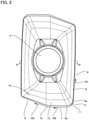
- Fig. 2 is a top view of cutting insert 10.
- first cutting edge 5 has a curved shape that protrudes toward an outer side of cutting insert 10. That is, an imaginary straight line that connects one end 5a of first cutting edge 5 to other end 5b of first cutting edge 5 extends over cutting insert 10.
- second cutting edge 6 extends from one end 5a of first cutting edge 5 along a first direction 101.
- third cutting edge 7 extends from other end 5b of first cutting edge 5 along a second direction 102.
- Second direction 102 intersects first direction 101.
- fourth cutting edge 8 extends, along third direction 103, from end 7a of third cutting edge 7 opposite to first cutting edge 5.
- Third direction 103 forms an acute angle with respect to second direction 102.
- Top surface 1 has a first rake face 11, a second rake face 12, a third rake face 13, and a fourth rake face 14.
- First cutting edge 5 is formed at a ridgeline between first side surface 3a and first rake face 11.
- Second cutting edge 6 is formed at a ridgeline between second side surface 3b and second rake face 12.
- Third cutting edge 7 is formed at a ridgeline between third side surface 3c and third rake face 13.
- Fourth cutting edge 8 is formed at a ridgeline between fourth side surface 3d and fourth rake face 14.
- First rake face 11 is located between second rake face 12 and third rake face 13, and is contiguous to second rake face 12 and third rake face 13.
- Third rake face 13 is located between first rake face 11 and fourth rake face 14 and is contiguous to first rake face 11 and fourth rake face 14.
- Fig. 3 is a side view of cutting insert 10 when viewed from the second side surface 3b side.
- second side surface 3b includes a first surface 3ba and a second surface 3bb.
- First surface 3ba is adjacent to second cutting edge 6.
- second cutting edge 6 is formed at a ridgeline between first surface 3ba and second rake face 12.
- First surface 3ba forms a flank face for second cutting edge 6.
- Second surface 3bb is contiguous to first surface 3ba on the side opposite to second cutting edge 6.
- a boundary line between first surface 3ba and second surface 3bb is defined as a boundary line 3bc.
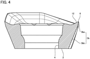
- Fig. 4 is a cross sectional view taken along IV-IV in Fig. 2 .
- Fig. 4 shows a cross sectional view that intersects second cutting edge 6.
- the inclination of second surface 3bb with respect to an imaginary straight line extending through second cutting edge 6 and orthogonal to bottom surface 2 is larger than the inclination of first surface 3ba with respect to this straight line.
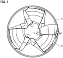
- Fig. 5 is a front view of cutting insert 10 mounted on a body 20.
- Fig. 6 is a cross sectional view taken along VI-VI in Fig. 5 .
- cutting insert 10 can be mounted on body 20 by bringing second surface 3bb into abutment with body 20. It should be noted that in the state in which cutting insert 10 is mounted on body 20, first surface 3ba is not in abutment with body 20.
- Fig. 7 is a cross sectional view taken along VII-VII in Fig. 3 .
- Fig. 7 shows a cross sectional view parallel to bottom surface 2.
- second surface 3bb When mounted on body 20, second surface 3bb is in abutment with body 20 at first position P1 and second position P2.
- second surface 3bb between first position P1 and second position P2 When mounted on body 20, second surface 3bb between first position P1 and second position P2 is not in abutment with body 20. More specifically, as shown in Fig. 7 , second surface 3bb between first position P1 and second position P2 forms a curve C that is recessed toward an inner side of cutting insert 10.
- the direction toward the inner side of cutting insert 10 is a direction from second surface 3bb toward mounting hole 4. That is, second surface 3bb between first position P1 and second position P2 is depressed. From another viewpoint, it can be said that between first position P1 and second position P2, an imaginary straight line (straight line L) that connects first position P1
- a depression amount DIS is defined to represent the maximum value of a distance between straight line L and curve C. Depression amount DIS is preferably less than or equal to 0.1 mm. Depression amount DIS is more preferably more than or equal to 0.005 mm and less than or equal to 0.05 mm.
- Fig. 8 is a cross sectional view taken along VIII-VIII in Fig. 3 .
- Fig. 8 shows a cross sectional view parallel to bottom surface 2 at a position close to bottom surface 2 with respect to the position in Fig. 7 .
- depression amount DIS is larger as the position is closer to bottom surface 2.
- a first cross section for example, shown in Fig. 7
- a second cross section for example, shown in Fig.
- depression amount DIS in the second cross section is larger than depression amount DIS in the first cross section.
- Fig. 9 is a cross sectional view taken along IX-IX in Fig. 3 .
- Fig. 9 shows a cross sectional view showing a cross section including boundary line 3bc when viewed in the direction orthogonal to bottom surface 2.
- boundary line 3bc forms a straight line when viewed in the top view.
- cutting insert 40 a cutting insert according to a comparative example.
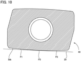
- Fig. 10 is a cross sectional view parallel to a bottom surface 2 of cutting insert 40.
- body 20 is indicated by a dotted line.
- cutting insert 40 is similar to cutting insert 10 in that second side surface 3b has a second surface 3bb.
- second surface 3bb is not in abutment with body 20 at first position P1 and second position P2, but is in abutment with body 20 at a third position P3 located between first position P1 and second position P2. That is, when viewed in the cross sectional view parallel to bottom surface 2, second surface 3bb between first position P1 and second position P2 forms a curve that protrudes toward an outer side of cutting insert 40.
- second surface 3bb and body 20 are in contact with each other at one point, with the result that cutting insert 40 may become unstable with respect to body 20 when cutting insert 40 is mounted on body 20. In other words, there is room for improvement in precision of mounting cutting insert 40 on body 20.
- second surface 3bb is in abutment with body 20 at first position P1 and second position P2 and is separated from body 20 between first position P1 and second position P2, with the result that second surface 3bb and body 20 are in contact with each other at two points.
- cutting insert 10 is less likely to be unstable with respect to body 20 when cutting insert 10 is mounted on body 20, thereby improving the precision of mounting on body 20.
- cutting insert 30 a configuration of a cutting insert (hereinafter, referred to as "cutting insert 30") according to the second embodiment will be described.
- cutting insert 30 a configuration of a cutting insert (hereinafter, referred to as "cutting insert 30") according to the second embodiment will be described.
- cutting insert 30 mainly describes differences from the configuration of cutting insert 10, and the same matters will not be described repeatedly.
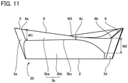
- Fig. 11 is a side view of cutting insert 30 when viewed from the second side surface 3b side.
- a second cutting edge 6 has a front end 6a and a rear end 6b.
- Second cutting edge 6 is contiguous to a first cutting edge 5 at front end 6a.
- Rear end 6b is an end opposite to front end 6a.
- the width of first surface 3ba on the front end 6a side is defined as a width W1.
- the width of first surface 3ba on the rear end 6b side is defined as a width W2.
- Width W2 is larger than width W1.
- the width of first surface 3ba has a minimum value at an intermediate position 6c between front end 6a and rear end 6b.
- the minimum value of the width of first surface 3ba is defined as a width W3. That is, the width of first surface 3ba is decreased in a direction from the front end 6a side toward intermediate position 6c, and has the minimum value at intermediate position 6c. Further, the width of first surface 3ba is increased in a direction from intermediate position 6c toward rear end 6b.
- Width W1, width W2 and width W3 are measured along a direction orthogonal to bottom surface 2.
- Width W3 is preferably less than or equal to 1 mm.
- Width W3 is more preferably less than or equal to 0.6 mm.
- Second cutting edge 6 is inclined such that a distance from bottom surface 2 becomes smaller in the direction from the front end 6a side toward intermediate position 6c. That is, the distance between second cutting edge 6 and bottom surface 2 is decreased in the direction from the front end 6a side toward intermediate position 6c. The distance between second cutting edge 6 and bottom surface 2 is measured along the direction orthogonal to bottom surface 2.
- Boundary line 3bc is inclined such that a distance from bottom surface 2 becomes larger in the direction from the front end 6a side toward intermediate position 6c. That is, the distance between boundary line 3bc and bottom surface 2 is increased in the direction from the front end 6a side toward intermediate position 6c. The distance between boundary line 3bc and bottom surface 2 is measured along the direction orthogonal to bottom surface 2.
- First surface 3ba forms a flank face for second cutting edge 6. Therefore, as the width of first surface 3ba is wider, the cutting edge strength of second cutting edge 6 is more secured. Cutting force exerted on second cutting edge 6 is large on the front end 6a side; however, in cutting insert 30, the width of first surface 3ba is increased in the direction from intermediate position 6c toward the front end 6a side, with the result that the cutting edge strength can be secured at a position on second cutting edge 6 to which relatively large cutting force is exerted.
- first surface 3ba As the width of first surface 3ba is larger, cutting resistance becomes larger due to contact between the flank face and a workpiece.
- the width of first surface 3ba is decreased in the direction from the front end 6a side toward intermediate position 6c, the cutting resistance can be reduced while securing the cutting edge strength on the front end 6a side when the amount of cut of cutting insert 30 is increased.
- width W2 is larger than width W1 (that is, the width of first surface 3ba is maximum at rear end 6b), interference with the workpiece can be prevented.
- flank wear is less likely to be progressed beyond boundary line 3bc. Therefore, according to cutting insert 30, the flank wear can be suppressed by the width of first surface 3ba being decreased in the direction from the front end 6a side toward intermediate position 6c.
- the distance between second cutting edge 6 and bottom surface 2 is decreased in the direction from the front end 6a side toward intermediate position 6c and the distance between boundary line 3bc and bottom surface 2 is increased in the direction from the front end 6a side toward intermediate position 6c, so that the width of second surface 3bb can be secured without increasing the thickness of cutting insert 30.
Landscapes
- Engineering & Computer Science (AREA)
- Mechanical Engineering (AREA)
- Milling Processes (AREA)
- Cutting Tools, Boring Holders, And Turrets (AREA)
Abstract
Description
- The present disclosure relates to a cutting insert. The present application claims a priority based on
Japanese Patent Application No. 2019-060278 filed on March 27, 2019 - PTL 1 (
Japanese Patent Laying-Open No. 2007-268641 Japanese Patent Laying-Open No. 2008-62382 PTL 1 and the cutting insert described inPTL 2 is mountable on a body by bringing a side surface of the cutting insert into abutment with the body. -
- PTL 1:
Japanese Patent Laying-Open No. 2007-268641 - PTL 2:
Japanese Patent Laying-Open No. 2008-62382 - A cutting insert of the present disclosure is mountable on the body and includes: an top surface; a bottom surface opposite to the top surface; a side surface contiguous to the top surface and the bottom surface; and a cutting edge formed at a ridgeline between the top surface and the side surface. The side surface has a first surface disposed adjacent to the cutting edge and a second surface contiguous to the first surface. When viewed in a cross sectional view parallel to the bottom surface, the second surface has a first position and a second position that are brought into abutment with the body when mounted on the body. Between the first position and the second position, an imaginary straight line extending through the first position and the second position is separated from the second surface.
-
-
Fig. 1 is a perspective view of acutting insert 10. -
Fig. 2 is a top view ofcutting insert 10. -
Fig. 3 is a side view ofcutting insert 10 when viewed from thesecond side surface 3b side. -
Fig. 4 is a cross sectional view taken along IV-IV inFig. 2 . -
Fig. 5 is a front view of cutting insert 10 mounted onbody 20. -
Fig. 6 is a cross sectional view taken along VI-VI inFig. 5 . -
Fig. 7 is a cross sectional view taken along VII-VII inFig. 3 . -
Fig. 8 is a cross sectional view taken along VIII-VIII inFig. 3 . -
Fig. 9 is a cross sectional view taken along IX-IX inFig. 3 . -
Fig. 10 is a cross sectional view parallel to abottom surface 2 of acutting insert 40. -
Fig. 11 is a side view of acutting insert 30 when viewed from thesecond side surface 3b side. - Each of the cutting insert described in
PTL 1 and the cutting insert described inPTL 2 has room for improvement in precision of mounting on the body. - It is an object of the present disclosure to provide a cutting insert mountable on a body with precision.
- According to the cutting insert of the present disclosure, the cutting insert is mountable on a body with precision.
- Hereinafter, embodiments of the present disclosure are listed and described.
- (1) A cutting insert according to an embodiment is mountable on a body. The cutting insert includes: a top surface; a bottom surface opposite to the top surface; a side surface contiguous to the top surface and the bottom surface; and a cutting edge formed at a ridgeline between the top surface and the side surface. The side surface has a first surface disposed adjacent to the cutting edge and a second surface contiguous to the first surface. When viewed in a cross sectional view parallel to the bottom surface, the second surface has a first position and a second position that are brought into abutment with the body when mounted on the body. Between the first position and the second position, an imaginary straight line extending through the first position and the second position is separated from the second surface.
- According to the cutting insert according to (1), the cutting insert can be mounted on the body with precision.
- (2) In the cutting insert according to (1), when viewed in the cross sectional view parallel to the bottom surface, the second surface between the first position and the second position may form a curve that is recessed toward an inner side of the cutting insert.
- (3) In the cutting insert according to (2), when viewed in the cross sectional view parallel to the bottom surface, a depression amount may be less than or equal to 0.1 mm, the depression amount being defined to represent a maximum value of a distance between the imaginary straight line and the curve.
- (4) In the cutting insert according to (3), when a first cross section is defined as a cross section that intersects the second surface and that is parallel to the bottom surface and a second cross section is defined as a cross section that is located close to the bottom surface with respect to the first cross section, that intersects the second surface, and that is parallel to the bottom surface, the depression amount in the second cross section may be larger than the depression amount in the first cross section.
- (5) In the cutting insert according to (4), when viewed in a top view, a boundary between the first surface and the second surface may form a straight line.
- (6) The cutting insert according to any one of (1) to (5) may further include a corner cutting edge contiguous to the cutting edge. The cutting edge may have a front end located on the corner cutting edge side and a rear end located opposite to the front end. A width of the first surface on the rear end side may be larger than the width of the first surface on the front end side. The width of the first surface may be decreased in a direction from the front end side toward an intermediate position located between the front end and the rear end, may have a minimum value at the intermediate position, and may be increased in a direction from the intermediate position toward the rear end side. In this case, cutting edge strength on the front end side can be secured, and an increase in cutting resistance when an amount of cut is increased can be suppressed. Further, in this case, interference with a workpiece can be prevented.
- (7) In the cutting insert according to (6), when viewed in a side view, a distance between the cutting edge and the bottom surface may be decreased in the direction from the front end side toward the intermediate position. When viewed in the side view, a distance between the bottom surface and a boundary between the first surface and the second surface may be increased in the direction from the front end side toward the intermediate position.
- (8) In the cutting insert according to (6) or (7), the minimum value of the width of the first surface may be less than or equal to 1 mm.
- Next, details of the embodiments of the present disclosure will be described with reference to figures. In the figures described below, the same or corresponding portions are denoted by the same reference characters, and the same matters will not be described repeatedly.
- Hereinafter, a configuration of a cutting insert (hereinafter, referred to as "
cutting insert 10") according to a first embodiment will be described. -
Cutting insert 10 is composed of, for example, a cemented carbide.Fig. 1 is a perspective view of cutting insert 10. As shown inFig. 1 ,cutting insert 10 has atop surface 1, abottom surface 2, afirst side surface 3a, asecond side surface 3b, athird side surface 3c, and afourth side surface 3d.Bottom surface 2 is opposite totop surface 1. -
First side surface 3a tofourth side surface 3d are contiguous totop surface 1 andbottom surface 2.First side surface 3a is located betweensecond side surface 3b andthird side surface 3c, and is contiguous tosecond side surface 3b andthird side surface 3c.Third side surface 3c is located betweenfirst side surface 3a andfourth side surface 3d, and is contiguous tofirst side surface 3a andfourth side surface 3d. A mountinghole 4 is formed in cuttinginsert 10. Mountinghole 4 extends through cuttinginsert 10 along a direction fromtop surface 1 towardbottom surface 2. - Cutting
insert 10 has a first cutting edge 5 (corner cutting edge), a second cutting edge 6 (main cutting edge), a third cutting edge 7 (flat cutting edge), and a fourth cutting edge 8 (sub cutting edge). When viewed in a top view, cuttinginsert 10 has a shape that is point-symmetrical with respect to the center of mountinghole 4. -
Fig. 2 is a top view of cuttinginsert 10. As shown inFig. 2 ,first cutting edge 5 has a curved shape that protrudes toward an outer side of cuttinginsert 10. That is, an imaginary straight line that connects oneend 5a offirst cutting edge 5 toother end 5b offirst cutting edge 5 extends over cuttinginsert 10. - When viewed in the top view,
second cutting edge 6 extends from oneend 5a offirst cutting edge 5 along afirst direction 101. When viewed in the top view,third cutting edge 7 extends fromother end 5b offirst cutting edge 5 along asecond direction 102.Second direction 102 intersectsfirst direction 101. When viewed in the top view,fourth cutting edge 8 extends, alongthird direction 103, fromend 7a ofthird cutting edge 7 opposite tofirst cutting edge 5.Third direction 103 forms an acute angle with respect tosecond direction 102. -
Top surface 1 has afirst rake face 11, asecond rake face 12, athird rake face 13, and afourth rake face 14.First cutting edge 5 is formed at a ridgeline betweenfirst side surface 3a andfirst rake face 11.Second cutting edge 6 is formed at a ridgeline betweensecond side surface 3b andsecond rake face 12.Third cutting edge 7 is formed at a ridgeline betweenthird side surface 3c andthird rake face 13.Fourth cutting edge 8 is formed at a ridgeline betweenfourth side surface 3d andfourth rake face 14. -
First rake face 11 is located betweensecond rake face 12 andthird rake face 13, and is contiguous tosecond rake face 12 andthird rake face 13.Third rake face 13 is located betweenfirst rake face 11 andfourth rake face 14 and is contiguous tofirst rake face 11 andfourth rake face 14. -
Fig. 3 is a side view of cuttinginsert 10 when viewed from thesecond side surface 3b side. As shown inFig. 3 ,second side surface 3b includes a first surface 3ba and a second surface 3bb. First surface 3ba is adjacent tosecond cutting edge 6. From another viewpoint, it can be said thatsecond cutting edge 6 is formed at a ridgeline between first surface 3ba andsecond rake face 12. First surface 3ba forms a flank face forsecond cutting edge 6. Second surface 3bb is contiguous to first surface 3ba on the side opposite tosecond cutting edge 6. A boundary line between first surface 3ba and second surface 3bb is defined as a boundary line 3bc. -
Fig. 4 is a cross sectional view taken along IV-IV inFig. 2 .Fig. 4 shows a cross sectional view that intersectssecond cutting edge 6. As shown inFig. 4 , the inclination of second surface 3bb with respect to an imaginary straight line extending throughsecond cutting edge 6 and orthogonal tobottom surface 2 is larger than the inclination of first surface 3ba with respect to this straight line. -
Fig. 5 is a front view of cuttinginsert 10 mounted on abody 20.Fig. 6 is a cross sectional view taken along VI-VI inFig. 5 . As shown inFigs. 5 and6 , cuttinginsert 10 can be mounted onbody 20 by bringing second surface 3bb into abutment withbody 20. It should be noted that in the state in which cuttinginsert 10 is mounted onbody 20, first surface 3ba is not in abutment withbody 20. -
Fig. 7 is a cross sectional view taken along VII-VII inFig. 3 .Fig. 7 shows a cross sectional view parallel tobottom surface 2. When mounted onbody 20, second surface 3bb is in abutment withbody 20 at first position P1 and second position P2. When mounted onbody 20, second surface 3bb between first position P1 and second position P2 is not in abutment withbody 20. More specifically, as shown inFig. 7 , second surface 3bb between first position P1 and second position P2 forms a curve C that is recessed toward an inner side of cuttinginsert 10. The direction toward the inner side of cuttinginsert 10 is a direction from second surface 3bb toward mountinghole 4. That is, second surface 3bb between first position P1 and second position P2 is depressed. From another viewpoint, it can be said that between first position P1 and second position P2, an imaginary straight line (straight line L) that connects first position P1 to second position P2 is separated from second surface 3bb. - A depression amount DIS is defined to represent the maximum value of a distance between straight line L and curve C. Depression amount DIS is preferably less than or equal to 0.1 mm. Depression amount DIS is more preferably more than or equal to 0.005 mm and less than or equal to 0.05 mm.
-
Fig. 8 is a cross sectional view taken along VIII-VIII inFig. 3 .Fig. 8 shows a cross sectional view parallel tobottom surface 2 at a position close tobottom surface 2 with respect to the position inFig. 7 . As shown inFigs. 7 and8 , depression amount DIS is larger as the position is closer tobottom surface 2. From another viewpoint, it can be said that when a first cross section (for example, shown inFig. 7 ) is defined as a cross section that intersects second surface 3bb and that is parallel tobottom surface 2 and a second cross section (for example, shown inFig. 8 ) is defined as a cross section that is located close tobottom surface 2 with respect to the first cross section, that intersects second surface 3bb, and that is parallel tobottom surface 2, depression amount DIS in the second cross section is larger than depression amount DIS in the first cross section. -
Fig. 9 is a cross sectional view taken along IX-IX inFig. 3 .Fig. 9 shows a cross sectional view showing a cross section including boundary line 3bc when viewed in the direction orthogonal tobottom surface 2. As shown inFig. 9 , boundary line 3bc forms a straight line when viewed in the top view. - The following describes effects of cutting
insert 10 in comparison with a cutting insert (hereinafter, referred to as "cuttinginsert 40") according to a comparative example. -
Fig. 10 is a cross sectional view parallel to abottom surface 2 of cuttinginsert 40. InFig. 10 ,body 20 is indicated by a dotted line. As shown inFig. 10 , cuttinginsert 40 is similar to cuttinginsert 10 in thatsecond side surface 3b has a second surface 3bb. - However, when cutting
insert 40 is mounted onbody 20, second surface 3bb is not in abutment withbody 20 at first position P1 and second position P2, but is in abutment withbody 20 at a third position P3 located between first position P1 and second position P2. That is, when viewed in the cross sectional view parallel tobottom surface 2, second surface 3bb between first position P1 and second position P2 forms a curve that protrudes toward an outer side of cuttinginsert 40. - As a result, second surface 3bb and
body 20 are in contact with each other at one point, with the result that cuttinginsert 40 may become unstable with respect tobody 20 when cuttinginsert 40 is mounted onbody 20. In other words, there is room for improvement in precision of mounting cuttinginsert 40 onbody 20. - On the other hand, in cutting
insert 10, second surface 3bb is in abutment withbody 20 at first position P1 and second position P2 and is separated frombody 20 between first position P1 and second position P2, with the result that second surface 3bb andbody 20 are in contact with each other at two points. As a result, cuttinginsert 10 is less likely to be unstable with respect tobody 20 when cuttinginsert 10 is mounted onbody 20, thereby improving the precision of mounting onbody 20. - Hereinafter, a configuration of a cutting insert (hereinafter, referred to as "cutting
insert 30") according to the second embodiment will be described. Here, the following mainly describes differences from the configuration of cuttinginsert 10, and the same matters will not be described repeatedly. -
Fig. 11 is a side view of cuttinginsert 30 when viewed from thesecond side surface 3b side. As shown inFig. 11 , asecond cutting edge 6 has afront end 6a and arear end 6b.Second cutting edge 6 is contiguous to afirst cutting edge 5 atfront end 6a.Rear end 6b is an end opposite tofront end 6a. - The width of first surface 3ba on the
front end 6a side is defined as a width W1. The width of first surface 3ba on therear end 6b side is defined as a width W2. Width W2 is larger than width W1. The width of first surface 3ba has a minimum value at anintermediate position 6c betweenfront end 6a andrear end 6b. The minimum value of the width of first surface 3ba is defined as a width W3. That is, the width of first surface 3ba is decreased in a direction from thefront end 6a side towardintermediate position 6c, and has the minimum value atintermediate position 6c. Further, the width of first surface 3ba is increased in a direction fromintermediate position 6c towardrear end 6b. - Width W1, width W2 and width W3 are measured along a direction orthogonal to
bottom surface 2. Width W3 is preferably less than or equal to 1 mm. Width W3 is more preferably less than or equal to 0.6 mm. -
Second cutting edge 6 is inclined such that a distance frombottom surface 2 becomes smaller in the direction from thefront end 6a side towardintermediate position 6c. That is, the distance betweensecond cutting edge 6 andbottom surface 2 is decreased in the direction from thefront end 6a side towardintermediate position 6c. The distance betweensecond cutting edge 6 andbottom surface 2 is measured along the direction orthogonal tobottom surface 2. - Boundary line 3bc is inclined such that a distance from
bottom surface 2 becomes larger in the direction from thefront end 6a side towardintermediate position 6c. That is, the distance between boundary line 3bc andbottom surface 2 is increased in the direction from thefront end 6a side towardintermediate position 6c. The distance between boundary line 3bc andbottom surface 2 is measured along the direction orthogonal tobottom surface 2. - From another point of view, it can be said that between
front end 6a andintermediate position 6c, the inclination ofsecond cutting edge 6 and the inclination of boundary line 3bc are opposite to each other. - Effects of cutting
insert 30 will be described below. Here, the following mainly describes differences from the effects of cuttinginsert 10, and the same matters will not be described repeatedly. - First surface 3ba forms a flank face for
second cutting edge 6. Therefore, as the width of first surface 3ba is wider, the cutting edge strength ofsecond cutting edge 6 is more secured. Cutting force exerted onsecond cutting edge 6 is large on thefront end 6a side; however, in cuttinginsert 30, the width of first surface 3ba is increased in the direction fromintermediate position 6c toward thefront end 6a side, with the result that the cutting edge strength can be secured at a position onsecond cutting edge 6 to which relatively large cutting force is exerted. - On the other hand, as the width of first surface 3ba is larger, cutting resistance becomes larger due to contact between the flank face and a workpiece. In cutting
insert 30, since the width of first surface 3ba is decreased in the direction from thefront end 6a side towardintermediate position 6c, the cutting resistance can be reduced while securing the cutting edge strength on thefront end 6a side when the amount of cut of cuttinginsert 30 is increased. Further, in cuttinginsert 30, since the width of first surface 3ba is increased in the direction fromintermediate position 6c toward therear end 6b side and width W2 is larger than width W1 (that is, the width of first surface 3ba is maximum atrear end 6b), interference with the workpiece can be prevented. - Since the inclination of second surface 3bb with respect to the straight line extending through
second cutting edge 6 and orthogonal tobottom surface 2 is larger than the inclination of first surface 3ba with respect to the straight line extending throughsecond cutting edge 6 and orthogonal tobottom surface 2, flank wear is less likely to be progressed beyond boundary line 3bc. Therefore, according to cuttinginsert 30, the flank wear can be suppressed by the width of first surface 3ba being decreased in the direction from thefront end 6a side towardintermediate position 6c. - In cutting
insert 30, the distance betweensecond cutting edge 6 andbottom surface 2 is decreased in the direction from thefront end 6a side towardintermediate position 6c and the distance between boundary line 3bc andbottom surface 2 is increased in the direction from thefront end 6a side towardintermediate position 6c, so that the width of second surface 3bb can be secured without increasing the thickness of cuttinginsert 30. - The embodiments disclosed herein are illustrative and non-restrictive in any respect. The scope of the present invention is defined by the terms of the claims, rather than the embodiments described above, and is intended to include any modifications within the scope and meaning equivalent to the terms of the claims.
- 1: top surface; 2: bottom surface; 3a: first side surface; 3b: second side surface; 3ba: first surface; 3bb: second surface; 3bc: boundary line; 3c: third side surface; 3d: fourth side surface; 4: mounting hole; 5: first cutting edge; 5a: one end; 5b: other end; 6: second cutting edge; 6a: front end; 6b: rear end; 6c: intermediate position; 7: third cutting edge; 7a: end; 8: fourth cutting edge; 10, 30, 40: cutting insert; 11: first rake face; 12: second rake face; 13: third rake face; 14: fourth rake face; 20: body; 101: first direction; 102: second direction; 103: third direction; C: curve; DIS: depression amount; L: straight line; P1: first position; P2: second position; P3: third position; W1, W2, W3: width.
Claims (9)
- A cutting insert mountable on a body, the cutting insert comprising:a top surface;a bottom surface opposite to the top surface;a side surface contiguous to the top surface and the bottom surface; anda cutting edge formed at a ridgeline between the top surface and the side surface, whereinthe side surface has a first surface disposed adjacent to the cutting edge and a second surface contiguous to the first surface,when viewed in a cross sectional view parallel to the bottom surface, the second surface has a first position and a second position that are brought into abutment with the body when mounted on the body, andbetween the first position and the second position, an imaginary straight line extending through the first position and the second position is separated from the second surface.
- The cutting insert according to claim 1, wherein when viewed in the cross sectional view parallel to the bottom surface, the second surface between the first position and the second position forms a curve that is recessed toward an inner side of the cutting insert.
- The cutting insert according to claim 2, wherein when viewed in the cross sectional view parallel to the bottom surface, a depression amount is less than or equal to 0.1 mm, the depression amount being defined to represent a maximum value of a distance between the imaginary straight line and the curve.
- The cutting insert according to claim 3, wherein when a first cross section is defined as a cross section that intersects the second surface and that is parallel to the bottom surface and a second cross section is defined as a cross section that is located close to the bottom surface with respect to the first cross section, that intersects the second surface, and that is parallel to the bottom surface, the depression amount in the second cross section is larger than the depression amount in the first cross section.
- The cutting insert according to claim 4, wherein when viewed in a top view, a boundary between the first surface and the second surface forms a straight line.
- The cutting insert according to any one of claims 1 to 5, further comprising a corner cutting edge contiguous to the cutting edge, whereinthe cutting edge has a front end located on the corner cutting edge side and a rear end located opposite to the front end,a width of the first surface on the rear end side is larger than the width of the first surface on the front end side, andthe width of the first surface is decreased in a direction from the front end side toward an intermediate position located between the front end and the rear end, has a minimum value at the intermediate position, and is increased in a direction from the intermediate position toward the rear end side.
- The cutting insert according to claim 6, whereinwhen viewed in a side view, a distance between the cutting edge and the bottom surface is decreased in the direction from the front end side toward the intermediate position, andwhen viewed in the side view, a distance between the bottom surface and a boundary between the first surface and the second surface is increased in the direction from the front end side toward the intermediate position.
- The cutting insert according to claim 6 or 7, wherein the minimum value is less than or equal to 1 mm.
- The cutting insert according to claim 5, further comprising a corner cutting edge contiguous to the cutting edge, whereinthe cutting edge has a front end located on the corner cutting edge side and a rear end located opposite to the front end,a width of the first surface on the rear end side is larger than the width of the first surface on the front end side,the width of the first surface is decreased in a direction from the front end side toward an intermediate position located between the front end and the rear end, has a minimum value at the intermediate position, and is increased in a direction from the intermediate position toward the rear end side,when viewed in a side view, a distance between the cutting edge and the bottom surface is decreased in the direction from the front end side toward the intermediate position,when viewed in the side view, a distance between the bottom surface and a boundary between the first surface and the second surface is increased in the direction from the front end side toward the intermediate position, andthe minimum value is less than or equal to 1 mm.
Applications Claiming Priority (2)
| Application Number | Priority Date | Filing Date | Title |
|---|---|---|---|
| JP2019060278 | 2019-03-27 | ||
| PCT/JP2020/013034 WO2020196526A1 (en) | 2019-03-27 | 2020-03-24 | Cutting insert |
Publications (2)
| Publication Number | Publication Date |
|---|---|
| EP3950196A1 true EP3950196A1 (en) | 2022-02-09 |
| EP3950196A4 EP3950196A4 (en) | 2022-05-25 |
Family
ID=72608486
Family Applications (1)
| Application Number | Title | Priority Date | Filing Date |
|---|---|---|---|
| EP20777741.8A Pending EP3950196A4 (en) | 2019-03-27 | 2020-03-24 | CUTTING INSERT |
Country Status (5)
| Country | Link |
|---|---|
| US (1) | US12134134B2 (en) |
| EP (1) | EP3950196A4 (en) |
| JP (1) | JP7019906B2 (en) |
| CN (1) | CN113573834B (en) |
| WO (1) | WO2020196526A1 (en) |
Families Citing this family (5)
| Publication number | Priority date | Publication date | Assignee | Title |
|---|---|---|---|---|
| WO2020196501A1 (en) * | 2019-03-27 | 2020-10-01 | 住友電工ハードメタル株式会社 | Cutting insert |
| JP6957827B2 (en) * | 2019-03-27 | 2021-11-02 | 住友電工ハードメタル株式会社 | Cutting insert |
| JP1716009S (en) * | 2021-09-22 | 2022-05-27 | Cutting tools | |
| JP1734037S (en) * | 2022-04-26 | 2023-01-10 | Cutting tools | |
| USD1078808S1 (en) * | 2022-04-26 | 2025-06-10 | Sumitomo Electric Hardmetal Corp. | Cutting tool |
Family Cites Families (72)
| Publication number | Priority date | Publication date | Assignee | Title |
|---|---|---|---|---|
| IL93883A (en) * | 1989-04-12 | 1993-02-21 | Iscar Ltd | Cutting insert for a milling cutting tool |
| US5207538A (en) * | 1990-05-14 | 1993-05-04 | Iscar Ltd. | Milling cutting insert |
| SE502541C2 (en) * | 1992-02-05 | 1995-11-06 | Sandvik Ab | Chip separating inserts with precise location-determining dimensions, as well as process for its preparation |
| IL101985A (en) * | 1992-05-25 | 1996-12-05 | Iscar Ltd | Exchangeable milling cutting inserts |
| IL103115A (en) | 1992-09-09 | 1996-09-12 | Iscar Ltd | Milling cutter insert |
| ES2303185T3 (en) * | 1993-01-20 | 2008-08-01 | Sandvik Intellectual Property Ab | CUTTING INSERT PART. |
| SE500719C2 (en) * | 1993-01-27 | 1994-08-15 | Sandvik Ab | Cut with twisted chip surface |
| SE500721C2 (en) * | 1993-01-27 | 1994-08-15 | Sandvik Ab | Cut with twisted chip surface |
| SE500703C2 (en) * | 1993-01-27 | 1994-08-15 | Sandvik Ab | Cut with a recess adjacent to a twisted release surface |
| IL108995A (en) * | 1994-03-16 | 1996-12-05 | Iscar Ltd | Exchangeable cutting insert |
| IL113121A0 (en) * | 1995-03-24 | 1995-06-29 | Iscar Ltd | A cutting insert for a milling cutter |
| IL111367A0 (en) * | 1994-10-23 | 1994-12-29 | Iscar Ltd | An exchangeable cutting insert |
| IL113122A0 (en) * | 1995-03-24 | 1995-06-29 | Iscar Ltd | A cutting insert |
| CN1154670A (en) * | 1995-03-24 | 1997-07-16 | 伊斯卡有限公司 | Insert blade |
| SE509595C2 (en) | 1996-01-25 | 1999-02-15 | Sandvik Ab | Cutting tool for metal cutting |
| US5853267A (en) * | 1996-08-22 | 1998-12-29 | Iscar Ltd. | Cutting insert |
| IL119776A0 (en) | 1996-12-06 | 1997-03-18 | Iscar Ltd | Cutting tool assembly |
| US5944456A (en) * | 1997-12-04 | 1999-08-31 | Kennametal Inc. | Three dimensional mill and milling inserts |
| SE518855C2 (en) * | 1998-03-10 | 2002-11-26 | Seco Tools Ab | Cutting tools and cutting tools |
| SE512040C2 (en) * | 1998-05-06 | 2000-01-17 | Sandvik Ab | Inserts for stick cutters |
| SE514032C2 (en) * | 1998-09-08 | 2000-12-11 | Seco Tools Ab | Tools and cutters for milling |
| KR100387406B1 (en) * | 2000-08-29 | 2003-06-18 | 한국야금 주식회사 | Cutting insert with curved cutting edge |
| IL141089A (en) * | 2001-01-25 | 2006-08-20 | Amir Satran | Cutting insert |
| US6503028B1 (en) | 2001-06-15 | 2003-01-07 | Sandvik Aktiebolag | Sintered cutting insert having center hole for clamp screw |
| JP4304935B2 (en) * | 2002-03-11 | 2009-07-29 | 三菱マテリアル株式会社 | Cutting tools and throwaway inserts |
| IL150015A (en) * | 2002-06-04 | 2007-06-17 | Amir Satran | Cutting insert and milling cutter |
| US7220083B2 (en) * | 2003-10-15 | 2007-05-22 | Tdy Industries, Inc. | Cutting insert for high feed face milling |
| KR101028986B1 (en) * | 2004-04-06 | 2011-04-12 | 미쓰비시 마테리알 가부시키가이샤 | Throwaway tip and throwaway rotary cutting tools |
| US7070363B2 (en) * | 2004-07-15 | 2006-07-04 | Kennametal Inc. | Cutting insert for high-speed milling cutter |
| JP2007044782A (en) * | 2005-08-08 | 2007-02-22 | Sumitomo Electric Hardmetal Corp | Throw-away tip and milling cutter using the same |
| SE529396C2 (en) * | 2005-12-08 | 2007-07-31 | Sandvik Intellectual Property | Tools and inserts for chip separating machining with secondary tools |
| SE529979C2 (en) | 2006-01-30 | 2008-01-22 | Sandvik Intellectual Property | Drill bit and drill bit where the orifice surface of the insert hole has a cross-sectional convex shape |
| JP2007268641A (en) | 2006-03-30 | 2007-10-18 | Kyocera Corp | Rotating tool, throw-away tip, and throw-away tip forming method |
| SE0600876L (en) * | 2006-04-20 | 2007-10-21 | Sandvik Intellectual Property | Tools and inserts for chip separating machining with primary and secondary meshes with rotationally symmetrical shape |
| KR100854081B1 (en) * | 2006-07-26 | 2008-08-25 | 한국야금 주식회사 | Cutting inserts for turning and milling |
| WO2008038804A1 (en) * | 2006-09-29 | 2008-04-03 | Kyocera Corporation | Cutting insert, cutting tool using the same, and cutting method |
| SE530629C2 (en) * | 2006-12-12 | 2008-07-22 | Sandvik Intellectual Property | Tools and basic body for chip separating machining including an elastically deformable spring in the cutting position |
| IL193284A (en) * | 2008-08-06 | 2014-06-30 | Iscar Ltd | Milling tools and cutting tool for it |
| DE202008018646U1 (en) * | 2008-08-31 | 2017-03-24 | Iscar Ltd. | cutting insert |
| KR101262566B1 (en) * | 2008-12-11 | 2013-05-08 | 대구텍 유한회사 | Cutting tools |
| US8491234B2 (en) * | 2009-02-12 | 2013-07-23 | TDY Industries, LLC | Double-sided cutting inserts for high feed milling |
| WO2010100953A1 (en) * | 2009-03-06 | 2010-09-10 | 三菱マテリアル株式会社 | Cutting inset and tool having cutting inserts |
| JP5525613B2 (en) | 2010-07-29 | 2014-06-18 | 京セラ株式会社 | Cutting insert, cutting tool, and method of manufacturing a cut product using the same |
| CN103025462B (en) * | 2010-08-11 | 2015-03-18 | 京瓷株式会社 | Cutting insert, cutting tool, and method for producing cut article using cutting insert and cutting tool |
| JP5589244B2 (en) | 2010-10-06 | 2014-09-17 | 大昭和精機株式会社 | insert |
| JP2012086303A (en) * | 2010-10-19 | 2012-05-10 | Sumitomo Electric Hardmetal Corp | Cutting edge replacement type tip and method for manufacturing the same |
| EP2471618A1 (en) * | 2010-12-28 | 2012-07-04 | VARGUS Ltd. | Milling cutter with a pocket at the front face and insert therefore |
| DE102011107789B4 (en) * | 2011-07-18 | 2015-05-28 | Kennametal Inc. | Gear cutter cutting insert and gear cutter with such a gear cutter cutting insert |
| JP5906976B2 (en) * | 2011-10-04 | 2016-04-20 | 三菱マテリアル株式会社 | Cutting insert and cutting edge changeable cutting tool |
| SE536590C2 (en) * | 2012-07-05 | 2014-03-11 | Sandvik Intellectual Property | Milling inserts with primary and secondary release surface as well as peripheral, narrow chip surface |
| KR101452073B1 (en) * | 2012-12-24 | 2014-10-16 | 대구텍 유한회사 | Cutting insert and milling cutter having the same |
| US9724761B2 (en) * | 2013-03-22 | 2017-08-08 | Kennametal India Limited | Cutting insert with a linear and a concave cutting edge portion |
| US9120156B2 (en) * | 2013-03-26 | 2015-09-01 | Iscar, Ltd. | Rhombus-shaped indexable cutting insert and cutting tool |
| AT14069U1 (en) * | 2014-02-20 | 2015-04-15 | Ceratizit Austria Gmbh | Indexable cutting insert and milling tool |
| KR101515994B1 (en) * | 2014-04-22 | 2015-05-04 | 한국야금 주식회사 | Single-faced insert and tool holder for mounting the same |
| KR101469135B1 (en) * | 2014-07-08 | 2014-12-04 | 한국야금 주식회사 | Cutting insert and cutting tool for mounting the same |
| EP2992991A1 (en) * | 2014-09-05 | 2016-03-09 | Sandvik Intellectual Property AB | Cutting insert and milling tool |
| WO2016084891A1 (en) * | 2014-11-27 | 2016-06-02 | 株式会社タンガロイ | Cutting insert and replaceable-edge rotary cutting tool |
| US10046398B2 (en) * | 2014-12-15 | 2018-08-14 | Seco Tools Ab | Reinforced double-sided cutting insert and cutting tool with reinforced double-sided cutting insert |
| EP3072616B1 (en) * | 2015-03-25 | 2018-10-10 | Sandvik Intellectual Property AB | Cutting insert and milling tool |
| WO2017010267A1 (en) * | 2015-07-15 | 2017-01-19 | 株式会社タンガロイ | Tool body and replaceable-blade-edge rotating cutting tool |
| EP3263257B1 (en) * | 2016-06-30 | 2024-12-25 | CERATIZIT Luxembourg S.à r.l. | Milling cutting insert and milling tool |
| EP3456450B1 (en) * | 2017-09-13 | 2022-12-21 | Sandvik Intellectual Property AB | Cutting insert and crank shaft milling tool |
| JP6954794B2 (en) | 2017-09-26 | 2021-10-27 | ダイハツ工業株式会社 | Internal combustion engine |
| EP3556498B1 (en) * | 2018-04-16 | 2021-02-17 | Seco Tools Ab | Cutting insert and milling tool |
| ES2926187T5 (en) * | 2018-06-21 | 2025-11-11 | Ceratizit Luxembourg Sarl | Double-sided tangential milling insert |
| JP6957827B2 (en) * | 2019-03-27 | 2021-11-02 | 住友電工ハードメタル株式会社 | Cutting insert |
| WO2020196501A1 (en) * | 2019-03-27 | 2020-10-01 | 住友電工ハードメタル株式会社 | Cutting insert |
| EP3964314A1 (en) * | 2020-09-02 | 2022-03-09 | AB Sandvik Coromant | Cutting insert and high feed milling tool |
| EP3984672B1 (en) * | 2020-10-13 | 2026-04-08 | Seco Tools Ab | Double-sided cutting insert and milling tool |
| JP7009720B1 (en) * | 2020-12-24 | 2022-01-26 | 住友電工ハードメタル株式会社 | Cutting inserts for rotary cutting tools and rotary cutting tools |
| JP7029686B1 (en) * | 2021-02-18 | 2022-03-04 | 株式会社タンガロイ | Cutting tools |
-
2020
- 2020-03-24 EP EP20777741.8A patent/EP3950196A4/en active Pending
- 2020-03-24 JP JP2021509453A patent/JP7019906B2/en active Active
- 2020-03-24 US US17/442,614 patent/US12134134B2/en active Active
- 2020-03-24 WO PCT/JP2020/013034 patent/WO2020196526A1/en not_active Ceased
- 2020-03-24 CN CN202080021387.2A patent/CN113573834B/en active Active
Also Published As
| Publication number | Publication date |
|---|---|
| JP7019906B2 (en) | 2022-02-16 |
| EP3950196A4 (en) | 2022-05-25 |
| CN113573834B (en) | 2024-10-01 |
| CN113573834A (en) | 2021-10-29 |
| US12134134B2 (en) | 2024-11-05 |
| JPWO2020196526A1 (en) | 2021-10-21 |
| US20220168820A1 (en) | 2022-06-02 |
| WO2020196526A1 (en) | 2020-10-01 |
Similar Documents
| Publication | Publication Date | Title |
|---|---|---|
| US12134134B2 (en) | Cutting insert | |
| CN1329154C (en) | Tangential cutting insert and milling cutter | |
| CN105980089B (en) | Cutting insert, cutting tool and manufacturing method of cutting workpiece | |
| EP3950197A1 (en) | Cutting tool body, cutting insert, and cutting tool | |
| US10166606B2 (en) | Cutting insert, cutting tool, and method for manufacturing machined product | |
| US11179785B2 (en) | Cutting insert and indexable edge rotary cutting tool | |
| KR101440957B1 (en) | Cutting insert | |
| US20120003052A1 (en) | Family of rotating cutting tools | |
| US12036614B2 (en) | Cutting insert | |
| EP2703105B1 (en) | Cutting insert and indexable rotary cutting tool | |
| US10384268B1 (en) | Grooving insert having rearwardly pointing arrowhead-shaped chip former | |
| US20200215625A1 (en) | Cutting insert and cutting tool | |
| EP4269008A1 (en) | Cutting insert for rotary cutting tool, and rotary cutting tool | |
| US10556277B2 (en) | Double-sided cutting insert having high feed rate and cutting tool equipped therewith | |
| JP5905965B2 (en) | Cutting insert, cutting tool, and method of manufacturing cut workpiece | |
| US20180326502A1 (en) | Cutting insert having a split cutting edge with leading and trailing component cutting edges | |
| US11117201B2 (en) | Single-sided high feed cutting insert and cutting tool equipped with same | |
| JP2004090198A (en) | Indexable tip | |
| JP5683208B2 (en) | Cutting insert, cutting tool, and cutting method of work material using the same | |
| US11260461B2 (en) | Cutting insert and cutting tool on which same is mounted | |
| JP2002126932A (en) | End mill | |
| JP2020011380A (en) | Cutting insert and cutting tool | |
| WO2015093408A1 (en) | Cutting insert, cutting tool, and manufacturing method for cut product |
Legal Events
| Date | Code | Title | Description |
|---|---|---|---|
| STAA | Information on the status of an ep patent application or granted ep patent |
Free format text: STATUS: THE INTERNATIONAL PUBLICATION HAS BEEN MADE |
|
| PUAI | Public reference made under article 153(3) epc to a published international application that has entered the european phase |
Free format text: ORIGINAL CODE: 0009012 |
|
| STAA | Information on the status of an ep patent application or granted ep patent |
Free format text: STATUS: REQUEST FOR EXAMINATION WAS MADE |
|
| 17P | Request for examination filed |
Effective date: 20210924 |
|
| AK | Designated contracting states |
Kind code of ref document: A1 Designated state(s): AL AT BE BG CH CY CZ DE DK EE ES FI FR GB GR HR HU IE IS IT LI LT LU LV MC MK MT NL NO PL PT RO RS SE SI SK SM TR |
|
| A4 | Supplementary search report drawn up and despatched |
Effective date: 20220428 |
|
| RIC1 | Information provided on ipc code assigned before grant |
Ipc: B23C 5/20 20060101ALI20220421BHEP Ipc: B23C 5/10 20060101AFI20220421BHEP |
|
| DAV | Request for validation of the european patent (deleted) | ||
| DAX | Request for extension of the european patent (deleted) | ||
| STAA | Information on the status of an ep patent application or granted ep patent |
Free format text: STATUS: EXAMINATION IS IN PROGRESS |
|
| 17Q | First examination report despatched |
Effective date: 20260218 |