JP6957827B2 - Cutting insert - Google Patents
Cutting insert Download PDFInfo
- Publication number
- JP6957827B2 JP6957827B2 JP2021509060A JP2021509060A JP6957827B2 JP 6957827 B2 JP6957827 B2 JP 6957827B2 JP 2021509060 A JP2021509060 A JP 2021509060A JP 2021509060 A JP2021509060 A JP 2021509060A JP 6957827 B2 JP6957827 B2 JP 6957827B2
- Authority
- JP
- Japan
- Prior art keywords
- cutting edge
- rake
- cutting
- angle
- view
- Prior art date
- Legal status (The legal status is an assumption and is not a legal conclusion. Google has not performed a legal analysis and makes no representation as to the accuracy of the status listed.)
- Active
Links
- 238000005520 cutting process Methods 0.000 title claims description 233
- 230000001154 acute effect Effects 0.000 claims description 4
- 238000000034 method Methods 0.000 description 4
- 230000000694 effects Effects 0.000 description 3
- 230000007423 decrease Effects 0.000 description 1
- 238000012986 modification Methods 0.000 description 1
- 230000004048 modification Effects 0.000 description 1
Images


Classifications
-
- B—PERFORMING OPERATIONS; TRANSPORTING
- B23—MACHINE TOOLS; METAL-WORKING NOT OTHERWISE PROVIDED FOR
- B23C—MILLING
- B23C5/00—Milling-cutters
- B23C5/16—Milling-cutters characterised by physical features other than shape
- B23C5/20—Milling-cutters characterised by physical features other than shape with removable cutter bits or teeth or cutting inserts
- B23C5/202—Plate-like cutting inserts with special form
-
- B—PERFORMING OPERATIONS; TRANSPORTING
- B23—MACHINE TOOLS; METAL-WORKING NOT OTHERWISE PROVIDED FOR
- B23C—MILLING
- B23C5/00—Milling-cutters
- B23C5/02—Milling-cutters characterised by the shape of the cutter
- B23C5/10—Shank-type cutters, i.e. with an integral shaft
- B23C5/109—Shank-type cutters, i.e. with an integral shaft with removable cutting inserts
-
- B—PERFORMING OPERATIONS; TRANSPORTING
- B23—MACHINE TOOLS; METAL-WORKING NOT OTHERWISE PROVIDED FOR
- B23C—MILLING
- B23C2200/00—Details of milling cutting inserts
- B23C2200/04—Overall shape
- B23C2200/0416—Irregular
-
- B—PERFORMING OPERATIONS; TRANSPORTING
- B23—MACHINE TOOLS; METAL-WORKING NOT OTHERWISE PROVIDED FOR
- B23C—MILLING
- B23C2200/00—Details of milling cutting inserts
- B23C2200/04—Overall shape
- B23C2200/0494—Rectangular
-
- B—PERFORMING OPERATIONS; TRANSPORTING
- B23—MACHINE TOOLS; METAL-WORKING NOT OTHERWISE PROVIDED FOR
- B23C—MILLING
- B23C2200/00—Details of milling cutting inserts
- B23C2200/08—Rake or top surfaces
- B23C2200/085—Rake or top surfaces discontinuous
-
- B—PERFORMING OPERATIONS; TRANSPORTING
- B23—MACHINE TOOLS; METAL-WORKING NOT OTHERWISE PROVIDED FOR
- B23C—MILLING
- B23C2200/00—Details of milling cutting inserts
- B23C2200/20—Top or side views of the cutting edge
- B23C2200/208—Wiper, i.e. an auxiliary cutting edge to improve surface finish
-
- B—PERFORMING OPERATIONS; TRANSPORTING
- B23—MACHINE TOOLS; METAL-WORKING NOT OTHERWISE PROVIDED FOR
- B23C—MILLING
- B23C2200/00—Details of milling cutting inserts
- B23C2200/28—Angles
- B23C2200/286—Positive cutting angles
-
- B—PERFORMING OPERATIONS; TRANSPORTING
- B23—MACHINE TOOLS; METAL-WORKING NOT OTHERWISE PROVIDED FOR
- B23C—MILLING
- B23C2200/00—Details of milling cutting inserts
- B23C2200/28—Angles
- B23C2200/287—Positive rake angles
-
- B—PERFORMING OPERATIONS; TRANSPORTING
- B23—MACHINE TOOLS; METAL-WORKING NOT OTHERWISE PROVIDED FOR
- B23C—MILLING
- B23C2200/00—Details of milling cutting inserts
- B23C2200/36—Other features of the milling insert not covered by B23C2200/04 - B23C2200/32
- B23C2200/365—Lands, i.e. the outer peripheral section of rake faces
Description
本開示は、切削インサートに関する。本出願は、2019年3月27日に出願した日本特許出願である特願2019−060279号に基づく優先権を主張する。当該日本特許出願に記載された全ての記載内容は、参照によって本明細書に援用される。 The present disclosure relates to cutting inserts. This application claims priority based on Japanese Patent Application No. 2019-060279, which is a Japanese patent application filed on March 27, 2019. All the contents of the Japanese patent application are incorporated herein by reference.
特許文献1(特開2007−44779号公報)には、スローアウェイチップが記載されている。特許文献1に記載のスローアウェイチップは、主切れ刃と、副切れ刃とを有している。
Patent Document 1 (Japanese Unexamined Patent Publication No. 2007-44779) describes a throw-away tip. The throw-away insert described in
特許文献1に記載のスローアウェイチップを用いた切削加工は、主切れ刃をワークの側壁面に切り込ませるとともに、副切れ刃をワークの底壁面に切り込ませることにより行われる。
The cutting process using the throw-away insert described in
本開示の切削インサートは、上面と、上面の反対面である底面と、上面及び底面に連なっている側面と、側面と上面との稜線に形成されているコーナ切れ刃、第1切れ刃、第2切れ刃及び第3切れ刃とを備える。コーナ切れ刃は、上面視において、第1端と、第1端の反対側の端である第2端とを有する。第1切れ刃は、上面視において、第1端から第1方向に沿って延在する。第2切れ刃は、上面視において、第2端から第1方向に交差する第2方向に沿って延在する。第3切れ刃は、上面視において、第2切れ刃から第2方向と鋭角をなす第3方向に沿って延在する。上面は、第1切れ刃に隣接して配置される第1すくい面と、第2切れ刃に隣接して配置される第2すくい面と、第3切れ刃に隣接して配置される第3すくい面とを有する。第1すくい面と底面に平行な基準面とがなす角度である第1すくい角は第3すくい面と基準面とがなす角度である第3すくい角よりも大きく、第3すくい角は第2すくい面と基準面とがなす角度である第2すくい角よりも大きい。 The cutting inserts of the present disclosure include a corner cutting edge, a first cutting edge, and a first cutting edge formed on a top surface, a bottom surface opposite to the top surface, a side surface connected to the top surface and the bottom surface, and a ridge line between the side surface and the top surface. It has two cutting edges and a third cutting edge. The corner cutting edge has a first end and a second end opposite to the first end in top view. The first cutting edge extends from the first end along the first direction in top view. The second cutting edge extends along a second direction intersecting the first direction from the second end in top view. The third cutting edge extends along a third direction forming an acute angle with the second direction from the second cutting edge in the top view. The upper surface has a first rake face arranged adjacent to the first cutting edge, a second rake surface arranged adjacent to the second cutting edge, and a third arranged adjacent to the third cutting edge. It has a rake face. The first rake angle, which is the angle formed by the first rake surface and the reference surface parallel to the bottom surface, is larger than the third rake angle, which is the angle formed by the third rake surface and the reference surface, and the third rake angle is the second. It is larger than the second rake angle, which is the angle formed by the rake face and the reference plane.
[本開示が解決しようとする課題]
特許文献1に記載のスローアウェイチップにおいては、切れ刃から削り出される切り屑の流出方向の制御に関して、特段の開示がない。[Issues to be solved by this disclosure]
In the throw-away insert described in
本開示の目的は、切れ刃から削り出される切り屑の流出方向を適切に制御することが可能な切削インサートを提供することである。 An object of the present disclosure is to provide a cutting insert capable of appropriately controlling the outflow direction of chips machined from a cutting edge.
[本開示の効果]
本開示の切削インサートによると、切れ刃から削り出される切り屑の流出方向を適切に制御することができる。[Effect of the present disclosure]
According to the cutting insert of the present disclosure, the outflow direction of chips cut out from the cutting edge can be appropriately controlled.
[本開示の実施形態の説明]
まず、本開示の実施形態を列記して説明する。[Explanation of Embodiments of the present disclosure]
First, the embodiments of the present disclosure will be listed and described.
一実施形態に係る切削インサートは、上面と、上面の反対面である底面と、上面及び底面に連なる側面と、側面と上面との稜線に形成されたコーナ切れ刃と、第1切れ刃と、第2切れ刃と、第3切れ刃とを備える。コーナ切れ刃は、上面視において、第1端と、第1端の反対側の端である第2端とを有する。第1切れ刃は、上面視において、第1端から第1方向に沿って延在する。第2切れ刃は、上面視において、第2端から第1方向に交差する第2方向に沿って延在する。第3切れ刃は、上面視において、第2切れ刃から第2方向と鋭角をなす第3方向に沿って延在する。上面は、第1切れ刃に隣接して配置される第1すくい面と、第2切れ刃に隣接して配置される第2すくい面と、第3切れ刃に隣接して配置される第3すくい面とを有する。第1すくい面と底面に平行な基準面とがなす角度である第1すくい角は第3すくい面と基準面とがなす角度である第3すくい角よりも大きく、第3すくい角は第2すくい面と基準面とがなす角度である第2すくい角よりも大きい。 The cutting insert according to one embodiment includes a top surface, a bottom surface opposite to the top surface, a side surface connected to the top surface and the bottom surface, a corner cutting edge formed on the ridgeline between the side surface and the top surface, and a first cutting edge. It includes a second cutting edge and a third cutting edge. The corner cutting edge has a first end and a second end opposite to the first end in top view. The first cutting edge extends from the first end along the first direction in top view. The second cutting edge extends along a second direction intersecting the first direction from the second end in top view. The third cutting edge extends along a third direction forming an acute angle with the second direction from the second cutting edge in the top view. The upper surface has a first rake face arranged adjacent to the first cutting edge, a second rake surface arranged adjacent to the second cutting edge, and a third arranged adjacent to the third cutting edge. It has a rake face. The first rake angle, which is the angle formed by the first rake surface and the reference surface parallel to the bottom surface, is larger than the third rake angle, which is the angle formed by the third rake surface and the reference surface, and the third rake angle is the second. It is larger than the second rake angle, which is the angle formed by the rake face and the reference plane.
上記の切削インサートによると、切れ刃から削り出される切り屑の流出方向を適切に制御することができる。より具体的には、上記の切削インサートにおいては、第1すくい角が大きくなっているため、第1切れ刃から削り出された切り屑が、第1切れ刃による加工面とは反対側に流出しやすい。そのため、上記の切削インサートによると、第1切れ刃による加工面に噛み込まれにくくなる。また、上記の切削インサートにおいては、第3すくい角が第2すくい角よりも大きくなっているため、第3切れ刃から削り出された切り屑が第2すくい面を避ける方向に沿って流出しやすい。そのため、上記の切削インサートによると、第3切れ刃により削り出された切り屑が、他の切れ刃から削り出された切り屑と絡まりにくくなる。 According to the above-mentioned cutting insert, the outflow direction of chips cut out from the cutting edge can be appropriately controlled. More specifically, in the above-mentioned cutting insert, since the first rake angle is large, the chips cut out from the first cutting edge flow out to the side opposite to the machined surface by the first cutting edge. It's easy to do. Therefore, according to the above-mentioned cutting insert, it is difficult to be bitten into the machined surface by the first cutting edge. Further, in the above-mentioned cutting insert, since the third rake angle is larger than the second rake angle, the chips cut out from the third cutting edge flow out along the direction avoiding the second rake face. Cheap. Therefore, according to the above-mentioned cutting insert, the chips machined by the third cutting edge are less likely to be entangled with the chips machined from other cutting edges.
上記の切削インサートにおいて、上面は、コーナ切れ刃に隣接する第4すくい面をさらに有していてもよい。 In the above cutting insert, the upper surface may further have a fourth rake face adjacent to the corner cutting edge.
上記の切削インサートにおいて、第4すくい面は、第1すくい面に連なる第1面と、第1面及び第2すくい面に連なる第2面とを含んでいてもよい。第1切れ刃及び第2切れ刃を通る断面視において、第1面は、上面から底面に向かう方向に凹の曲線形状を有していてもよい。第1切れ刃及び第2切れ刃を通る断面視において、第2面は、底面から上面に向かう方向に凸の曲線形状を有していてもよい。この場合、第1切れ刃により削り出された切り屑は、第4すくい面を避ける方向に沿って流出しやすくなるため、第1切れ刃により削り出された切り屑が、他の切れ刃から削り出された切り屑と絡まりにくくなる。 In the above cutting insert, the fourth rake face may include a first surface connected to the first rake surface and a second surface connected to the first surface and the second rake surface. In the cross-sectional view through the first cutting edge and the second cutting edge, the first surface may have a concave curved shape in the direction from the upper surface to the bottom surface. In the cross-sectional view through the first cutting edge and the second cutting edge, the second surface may have a curved shape that is convex in the direction from the bottom surface to the top surface. In this case, the chips machined by the first cutting edge tend to flow out along the direction avoiding the fourth rake face, so that the chips machined by the first cutting edge are removed from other cutting edges. It becomes difficult to get entangled with the cut chips.
上記の切削インサートにおいて、第2方向と第3方向とがなす角度は5°以上45°以下であってもよい。 In the above cutting insert, the angle formed by the second direction and the third direction may be 5 ° or more and 45 ° or less.
上記の切削インサートにおいて、第2方向と第3方向とがなす角度は15°以上35°以下であってもよい。 In the above cutting insert, the angle formed by the second direction and the third direction may be 15 ° or more and 35 ° or less.
上記の切削インサートにおいて、第1切れ刃は、第1端から離れるにしたがって底面に近づくように傾斜していてもよい。この場合、第1切れ刃により削り出された切り屑は、第4すくい面を避ける方向に流出しやすくなるため、第1切れ刃から削り出された切り屑は、他の切れ刃から削り出された切り屑とさらに絡まりにくくなる。 In the above-mentioned cutting insert, the first cutting edge may be inclined so as to approach the bottom surface as the distance from the first end ends increases. In this case, the chips machined by the first cutting edge tend to flow out in the direction avoiding the fourth rake face, so that the chips machined from the first cutting edge are machined from other cutting edges. It becomes even more difficult to get entangled with the chips that have been cut.
上記の切削インサートにおいて、第1切れ刃と基準面とがなす角度は、第2方向から見た側面視において、2°以上20°以下であってもよい。 In the above-mentioned cutting insert, the angle formed by the first cutting edge and the reference surface may be 2 ° or more and 20 ° or less when viewed from the side view from the second direction.
上記の切削インサートにおいて、第1切れ刃と基準面とがなす角度は、第2方向から見た側面視において、5°以上15°以下であってもよい。 In the above-mentioned cutting insert, the angle formed by the first cutting edge and the reference surface may be 5 ° or more and 15 ° or less when viewed from the side view from the second direction.
上記の切削インサートにおいて、第3切れ刃は、第2切れ刃から離れるにしたがって底面に近づくように傾斜していてもよい。この場合には、第3切れ刃から削り出された切り屑は、第2すくい面を避ける方向に沿ってさらに流出しやすくなる。そのため、第3切れ刃から削り出された切り屑が、他の切れ刃から削り出された切り屑とさらに絡まりにくくなる。 In the above-mentioned cutting insert, the third cutting edge may be inclined so as to approach the bottom surface as the distance from the second cutting edge increases. In this case, the chips carved from the third cutting edge are more likely to flow out along the direction avoiding the second rake face. Therefore, the chips machined from the third cutting edge are less likely to be entangled with the chips machined from other cutting edges.
上記の切削インサートにおいて、第3切れ刃と基準面とがなす角度は、第1方向から見た側面視において10°以上40°以下であってもよい。 In the above-mentioned cutting insert, the angle formed by the third cutting edge and the reference surface may be 10 ° or more and 40 ° or less when viewed from the side in the first direction.
上記の切削インサートにおいて、第3切れ刃と基準面とがなす角度は、第1方向から見た側面視において15°以上30°以下であってもよい。 In the above-mentioned cutting insert, the angle formed by the third cutting edge and the reference surface may be 15 ° or more and 30 ° or less in the side view from the first direction.
[本開示の実施形態の詳細]
次に、本開示の実施形態の詳細を、図面を参酌しながら説明する。以下の図面においては、同一又は相当する部分に同一の参照符号を付し、重複する説明は繰り返さない。[Details of Embodiments of the present disclosure]
Next, the details of the embodiments of the present disclosure will be described with reference to the drawings. In the following drawings, the same or corresponding parts are designated by the same reference numerals, and duplicate explanations will not be repeated.
(実施形態に係る切削インサートの構成)
以下に、実施形態に係る切削インサート(以下においては、「切削インサート10」という)の構成を説明する。(Structure of cutting insert according to embodiment)
Hereinafter, the configuration of the cutting insert (hereinafter referred to as “cutting
図1は、切削インサート10の斜視図である。図1に示されるように、切削インサート10は、上面1と、底面2と、側面3とを有している。底面2は上面1の反対面である。側面3は、上面1及び底面2に連なっている。切削インサート10は、例えば超硬合金で形成されている。
FIG. 1 is a perspective view of the cutting
切削インサート10は、コーナ切れ刃4と、第1切れ刃5(主切れ刃)と、第2切れ刃6(さらい刃)と、第3切れ刃7(副切れ刃)とを有している。コーナ切れ刃4、第1切れ刃5、第2切れ刃6及び第3切れ刃7は、上面1と側面3の稜線に形成されている。
The cutting
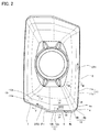
図2は、切削インサート10の上面図である。図2に示されるように、コーナ切れ刃4は、上面視において、第1端4aと、第2端4bとを有している。第2端4bは、第1端4aの反対側の端である。コーナ切れ刃4は、上面視において曲線形状を有している。この曲線形状は、切削インサート10の外側に向かって凸形状になっている。このことを別の観点から言えば、第1端4aと第2端4bとを結んだ仮想直線は、切削インサート10(上面1)上を通過する。
FIG. 2 is a top view of the cutting
第1切れ刃5は、上面視において、第1端4aから第1方向DR1に沿って延在している。第1方向DR1は、好ましくは、切削インサート10が取り付けられるボディ20(図1及び図2中において図示せず)の回転中心軸Aの方向に沿っている。第2切れ刃6は、上面視において、第2端4bから第2方向DR2に沿って延在している。第2方向DR2は、第1方向DR1に交差している。
The
第3切れ刃7は、上面視において、第2切れ刃6から第3方向DR3に沿って延在している。第3方向DR3は、第2方向DR2と鋭角をなす方向である。第2方向DR2と第3方向DR3とがなす角度である角度θ1は、好ましくは、5°以上45°以下である。角度θ1は、さらに好ましくは、15°以上35°以下である。
The
上面1は、第1すくい面11と、第2すくい面12と、第3すくい面13と、第4すくい面14とを有している。第1すくい面11は第1切れ刃5に隣接して配置されており、第2すくい面12は第2切れ刃6に隣接して配置されている。第3すくい面13は、第3切れ刃7に隣接して配置されている。第4すくい面14は、コーナ切れ刃4に隣接して配置されている。
The
このことを別の観点から言えば、第1切れ刃5は第1すくい面11と側面3との稜線に形成されており、第2切れ刃6は第2すくい面12と側面3との稜線に形成されており、第3切れ刃7は第3すくい面13と側面3との稜線に形成されており、コーナ切れ刃4は第4すくい面14と側面3の稜線に形成されている。
From another point of view, the
第2すくい面12は、第3すくい面13と第4すくい面14との間にあり、第3すくい面13及び第4すくい面14に連なっている。第4すくい面は、第1すくい面11と第2すくい面12との間にあり、第1すくい面11及び第2すくい面12に連なっている。
The
図3は、図2のIII−IIIに沿う断面図である。図3には、第1切れ刃5と直交している切削インサート10の断面図が示されている。図3に示されるように、第1すくい面11は、第1面11aと、第2面11bとを有している。第1面11aは、側面3に連なっている。第2面11bは、第1切れ刃5とは反対側において第1面11aに連なっている。
FIG. 3 is a cross-sectional view taken along the line III-III of FIG. FIG. 3 shows a cross-sectional view of the cutting
第1切れ刃5に直交する方向において、第1面11aの幅は、第2面11bの幅よりも狭い。すなわち、第1面11aは、ランドになっている。なお、第1すくい面11は、第1面11aを有していなくてもよい。第1すくい面11と底面2とは、角度θ2(第1すくい角)をなしている。角度θ2は、第2面11bと底面2に平行な基準面Pとがなす角度により決定される。
The width of the
図4は、図2のIV−IVに沿う断面図である。図4には、第2切れ刃6と直交している切削インサート10の断面図が示されている。第2すくい面12は、図4に示されるように、第1面12aと、第2面12bとを有している。第1面12aは、側面3に連なっている。第2面12bは、第2切れ刃6とは反対側において、第1面12aに連なっている。
FIG. 4 is a cross-sectional view taken along the line IV-IV of FIG. FIG. 4 shows a cross-sectional view of the cutting
第2切れ刃6に直交する方向において、第1面12aの幅は、第2面12bの幅よりも狭い。すなわち、第1面12aは、ランドになっている。なお、第2すくい面12は、第1面12aを有していなくてもよい。第2すくい面12と底面2とは、角度θ3(第2すくい角)をなしている。角度θ3は、第2面12bと基準面Pとがなす角度により決定される。
The width of the
図5は、図2のV−Vに沿う断面図である。図5には、第3切れ刃7に直交する切削インサート10の断面図が示されている。図5に示されるように、第3すくい面13は、第1面13aと、第2面13bとを有している。第1面13aは側面3に連なっており、第2面13bは第3切れ刃7とは反対側において第1面13aに連なっている。
FIG. 5 is a cross-sectional view taken along the line VV of FIG. FIG. 5 shows a cross-sectional view of the cutting
第3切れ刃7に直交する方向において、第1面13aの幅は、第2面13bの幅よりも狭い。すなわち、第1面13aは、ランドになっている。なお、第3すくい面13は、第1面13aを有していなくてもよい。第3すくい面13と底面2とは、角度θ4(第3すくい角)をなしている。角度θ4は、第2面13bと基準面Pとがなす角度により決定される。
The width of the
角度θ2は、角度θ4よりも大きい。角度θ4は、角度θ3よりも大きい。すなわち、角度θ2、角度θ3及び角度θ4は、角度θ2>角度θ4>角度θ3との関係を充足している。 The angle θ2 is larger than the angle θ4. The angle θ4 is larger than the angle θ3. That is, the angle θ2, the angle θ3, and the angle θ4 satisfy the relationship of the angle θ2> the angle θ4> the angle θ3.
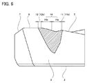
図6は、図2のVI−VIに沿う断面図である。図6には、第1切れ刃5及び第2切れ刃6を通る断面図が示されている。図6に示されるように、第4すくい面14は、第1面14aと、第2面14bとを有している。第1面14aは、第1すくい面11に連なっている。第2面14bは、第1面14aと第2すくい面12との間にあり、第1面14a及び第2すくい面12に連なっている。
FIG. 6 is a cross-sectional view taken along the line VI-VI of FIG. FIG. 6 shows a cross-sectional view passing through the
第1面14aは、第1切れ刃5及び第2切れ刃6を通る断面視において、上面1から底面2に向かう方向に凹(図6中において、下に凸)の曲線形状になっている。第2面14bは、第1切れ刃5及び第2切れ刃6を通る断面視において、底面2から上面1に向かう方向に凸(図6中において、上に凸)の曲線形状になっている。このことを別の観点から言えば、第1面14aと第2面14bとの境界は、第1切れ刃5及び第2切れ刃6を通る断面視において、第4すくい面14の曲線形状の変曲点になっている。
The
第4すくい面14は、第1すくい面11側から第2すくい面12側に向かうにしたがって、一旦、底面2との間の距離が小さくなっている。第4すくい面14は、さらに第2すくい面側に向かうにしたがって、底面2との距離が大きくなっている。第1すくい面11側の端における第4すくい面14と底面2との間の距離は、第2すくい面12側の端における第4すくい面14と底面2との間の距離よりも小さくなっている。
The distance between the
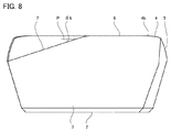
図7は、第2方向DR2から見た切削インサート10の側面図である。図7に示されるように、第1切れ刃5は、第1端4aから離れるにつれて底面2に近づくように傾斜している。
FIG. 7 is a side view of the cutting
第1切れ刃5と底面2(基準面P)とは、第2方向DR2から見た側面視において、角度θ5をなしている。角度θ5は、2°以上20°以下であることが好ましい。角度θ5は、5°以上15°以下であることがさらに好ましい。
The
図8は、第1方向DR1から見た切削インサート10の側面図である。図8に示されるように、第3切れ刃7は、第2切れ刃6から離れるにつれて底面2に近づくように傾斜している。
FIG. 8 is a side view of the cutting
第3切れ刃7と底面2(基準面P)とは、第1方向DR1から見た側面視において、角度θ6をなしている。角度θ6は、10°以上40°以下であることが好ましい。角度θ6は、15°以上30°以下であることがさらに好ましい。
The
(実施形態に係る切削インサートを用いた切削加工)
以下に、切削インサート10を用いた切削加工を説明する。(Cutting process using the cutting insert according to the embodiment)
The cutting process using the cutting
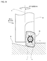
図9は、切削インサート10を用いたランピング加工を示す模式図である。図9に示されるように、切削インサート10は、ボディ20に取り付けられる。工作機械により、ボディ20は、回転中心軸A周りに回転する。
FIG. 9 is a schematic view showing a ramping process using the cutting
切削インサート10を用いたランピング加工では、ボディ20は、回転中心軸A周りに回転している状態で、ワークWに対してボディ20の径方向(図9中における右方)及びボディ20の軸方向(図9中における下方)に送られる。これにより、第1切れ刃5がワークWの側壁面に切り込むとともに、第2切れ刃6及び第3切れ刃7がワークWの底壁面に切り込むことにより、ワークWに底壁面が傾斜した溝を形成するランピング加工が行われる。
In the ramping process using the cutting
(実施形態に係る切削インサートの効果)
以下に、切削インサート10の効果を説明する。(Effect of cutting insert according to the embodiment)
The effect of the cutting
切削インサート10においては、第1切れ刃5のすくい角(角度θ2)が他の切れ刃のすくい角よりも大きくなっているため、第1切れ刃5から削り出された切り屑と第1すくい面11との間の接触抵抗は、相対的に小さくなっている。そのため、第1切れ刃5により削り出された切り屑は、第1切れ刃5による加工面とは反対側に流出しやすく、第1切れ刃5による加工面とボディ20との間に巻き込まれにくい。
In the cutting
切削インサート10においては第3切れ刃7のすくい角(角度θ4)が第2切れ刃6のすくい角(角度θ3)よりも大きくなっているため、第3切れ刃7から削り出された切り屑は、第2すくい面12上を通過する場合よりも第3すくい面上を通過する場合の方が、接触抵抗が小さくなる。そのため、第3切れ刃7から削り出された切り屑は、第2すくい面12を避ける方向に沿って流出しやすい。その結果、切削インサート10によると、第3切れ刃7から削り出された切り屑が、他の切れ刃から削り出された切り屑と絡まりにくくなる。
In the cutting
切削インサート10において、第1面14a及び第2面14bは、断面視において、それぞれ下に凸の曲線形状及び上に凸の曲線形状を有しているため、第4すくい面14は、第1すくい面11側から第2すくい面12側にかけて立ち上がった形状を有していることになる。そのため、第1切れ刃5から削り出された切り屑が第4すくい面14上を通過しようとすると、接触抵抗が大きくなる。その結果、第1切れ刃5から削り出された切り屑は、第4すくい面14を避ける方向に流出しやすくなり、他の切れ刃から削り出された切り屑と絡まりにくくなる。
In the cutting
第1切れ刃5が第1端4aから離れるにしたがって底面2に近づくように傾斜している場合、第1切れ刃5から削り出された切り屑は、当該傾斜の方向に沿って流出した方が、第1すくい面11との接触抵抗が低下する。そのため、この場合、第1切れ刃5から削り出された切り屑は、第4すくい面14を避ける方向にさらに流出しやすくなり、他の切れ刃から削り出された切り屑とさらに絡まりにくくなる。
When the
第3切れ刃7が第2切れ刃6から離れるにしたがって底面2に近づくように傾斜している場合、第3切れ刃7から削り出された切り屑は、当該傾斜の方向に沿って流出した方が第3すくい面13との接触抵抗が低下する。そのため、この場合、第3切れ刃7から削り出された切り屑は、第2すくい面12を避ける方向にさらに流出しやすくなり、他の切れ刃から削り出された切り屑とさらに絡まりにくくなる。
When the
今回開示された実施形態は全ての点で例示であって、制限的なものではないと考えられるべきである。本発明の範囲は、上記した実施形態ではなく、請求の範囲によって示され、請求の範囲と均等の意味及び範囲内での全ての変更が含まれることが意図される。 The embodiments disclosed this time should be considered as exemplary in all respects and not restrictive. The scope of the present invention is indicated by the claims, not the embodiment described above, and is intended to include all modifications within the meaning and scope equivalent to the claims.
1 上面、2 底面、3 側面、4 コーナ切れ刃、4a 第1端、4b 第2端、5 第1切れ刃、6 第2切れ刃、7 第3切れ刃、10 切削インサート、11 第1すくい面、11a,12a,13a,14a 第1面、11b,12b,13b,14b 第2面、12 第2すくい面、13 第3すくい面、14 第4すくい面、20 ボディ、A 回転中心軸、DR1 第1方向、DR2 第2方向、DR3 第3方向、P 基準面、W ワーク、θ1 第2方向と第3方向とがなす角度、θ2 第1すくい角、θ3 第2すくい角、θ3 第3すくい角、θ5 第1切れ刃と底面(基準面)とがなす角度、θ6 第3切れ刃と底面(基準面)とがなす角度。 1 Top surface, 2 Bottom surface, 3 Side surface, 4 Corner cutting edge, 4a 1st end, 4b 2nd end, 5 1st cutting edge, 6 2nd cutting edge, 7 3rd cutting edge, 10 cutting insert, 11 1st rake Surfaces, 11a, 12a, 13a, 14a 1st surface, 11b, 12b, 13b, 14b 2nd surface, 12 2nd rake surface, 13 3rd rake surface, 14 4th rake surface, 20 body, A rotation center axis, DR1 1st direction, DR2 2nd direction, DR3 3rd direction, P reference plane, W work, θ1 Angle between 2nd and 3rd directions, θ2 1st rake angle, θ3 2nd rake angle, θ3 3rd The rake angle, the angle formed by the θ5 first cutting edge and the bottom surface (reference surface), and the angle formed by the θ6 third cutting edge and the bottom surface (reference surface).
Claims (10)
前記上面の反対面である底面と、
前記上面及び前記底面に連なる側面と、
前記側面と前記上面との稜線に形成されたコーナ切れ刃、第1切れ刃、第2切れ刃及び第3切れ刃とを備え、
前記コーナ切れ刃は、上面視において、第1端と、前記第1端の反対側の端である第2端とを有し、
前記第1切れ刃は、上面視において、前記第1端から第1方向に沿って延在しており、
前記第2切れ刃は、上面視において、前記第2端から前記第1方向に交差する第2方向に沿って延在しており、
前記第3切れ刃は、上面視において、前記第2切れ刃から前記第2方向と鋭角をなす第3方向に沿って延在しており、
前記上面は、前記第1切れ刃に隣接して配置される第1すくい面と、前記第2切れ刃に隣接して配置される第2すくい面と、前記第3切れ刃に隣接して配置される第3すくい面とを有し、
前記第1すくい面と前記底面に平行な基準面とがなす角度である第1すくい角は、前記第3すくい面と前記基準面とがなす角度である第3すくい角よりも大きく、
前記第3すくい角は、前記第2すくい面と前記基準面とがなす角度である第2すくい角よりも大きく、
前記第1切れ刃は、前記第1端から離れるにしたがって前記底面に近づくように傾斜している、切削インサート。On the top and
The bottom surface, which is the opposite surface of the top surface,
The upper surface and the side surface connected to the bottom surface,
A corner cutting edge, a first cutting edge, a second cutting edge, and a third cutting edge formed on the ridge line between the side surface and the upper surface are provided.
The corner cutting edge has a first end and a second end opposite to the first end in a top view.
The first cutting edge extends from the first end along the first direction in a top view.
The second cutting edge extends from the second end along a second direction intersecting the first direction in a top view.
The third cutting edge extends from the second cutting edge along a third direction forming an acute angle with the second direction in a top view.
The upper surface is arranged adjacent to the first cutting edge, the second rake surface arranged adjacent to the second cutting edge, and the third cutting edge. Has a third rake face to be
The first rake angle, which is the angle formed by the first rake surface and the reference surface parallel to the bottom surface, is larger than the third rake angle, which is the angle formed by the third rake surface and the reference surface.
The third rake angle is larger than the second rake angle, which is the angle formed by the second rake surface and the reference surface.
The first cutting edge is a cutting insert that is inclined so as to approach the bottom surface as the distance from the first end ends increases.
前記第1面は、前記第1切れ刃及び前記第2切れ刃を通る断面視において、前記上面から前記底面に向かう方向に凹の曲線形状を有し、
前記第2面は、前記第1切れ刃及び前記第2切れ刃を通る断面視において、前記底面から前記上面に向かう方向に凸の曲線形状を有する、請求項2に記載の切削インサート。The fourth rake surface includes a first surface connected to the first rake surface and a second surface connected to the first surface and the second rake surface.
The first surface has a concave curved shape in the direction from the upper surface to the bottom surface in a cross-sectional view passing through the first cutting edge and the second cutting edge.
The cutting insert according to claim 2, wherein the second surface has a curved shape that is convex in the direction from the bottom surface to the top surface in a cross-sectional view passing through the first cutting edge and the second cutting edge.
Applications Claiming Priority (3)
| Application Number | Priority Date | Filing Date | Title |
|---|---|---|---|
| JP2019060279 | 2019-03-27 | ||
| JP2019060279 | 2019-03-27 | ||
| PCT/JP2020/011203 WO2020195976A1 (en) | 2019-03-27 | 2020-03-13 | Cutting insert |
Publications (2)
| Publication Number | Publication Date |
|---|---|
| JPWO2020195976A1 JPWO2020195976A1 (en) | 2021-10-21 |
| JP6957827B2 true JP6957827B2 (en) | 2021-11-02 |
Family
ID=70469827
Family Applications (1)
| Application Number | Title | Priority Date | Filing Date |
|---|---|---|---|
| JP2021509060A Active JP6957827B2 (en) | 2019-03-27 | 2020-03-13 | Cutting insert |
Country Status (4)
| Country | Link |
|---|---|
| US (1) | US20220168825A1 (en) |
| JP (1) | JP6957827B2 (en) |
| DE (1) | DE202020101585U1 (en) |
| WO (1) | WO2020195976A1 (en) |
Families Citing this family (1)
| Publication number | Priority date | Publication date | Assignee | Title |
|---|---|---|---|---|
| EP3950196A4 (en) * | 2019-03-27 | 2022-05-25 | Sumitomo Electric Hardmetal Corp. | Cutting insert |
Family Cites Families (22)
| Publication number | Priority date | Publication date | Assignee | Title |
|---|---|---|---|---|
| IL110785A (en) * | 1994-08-25 | 1998-04-05 | Iscar Ltd | Cutting insert for a rotary milling cutter |
| SE514014C2 (en) * | 1998-05-06 | 2000-12-11 | Sandvik Ab | Indexable cutting insert for rotary end mills |
| SE512040C2 (en) * | 1998-05-06 | 2000-01-17 | Sandvik Ab | Inserts for stick cutters |
| SE514032C2 (en) * | 1998-09-08 | 2000-12-11 | Seco Tools Ab | Tools and cutters for milling |
| US7004689B2 (en) * | 2004-01-09 | 2006-02-28 | Kennametal Inc. | High-speed milling cutter and insert |
| US7070363B2 (en) * | 2004-07-15 | 2006-07-04 | Kennametal Inc. | Cutting insert for high-speed milling cutter |
| US7040844B1 (en) * | 2005-03-08 | 2006-05-09 | Mitsubishi Materials Corporation | Throwaway insert and throwaway-type rotary cutting tool |
| JP2007044779A (en) | 2005-08-08 | 2007-02-22 | Sumitomo Electric Hardmetal Corp | Throw-away tip and milling cutter using it |
| JP2007044782A (en) * | 2005-08-08 | 2007-02-22 | Sumitomo Electric Hardmetal Corp | Throw-away tip and milling cutter using it |
| WO2012002267A1 (en) * | 2010-06-30 | 2012-01-05 | 京セラ株式会社 | Insert and cutting tool, as well as method of manufacturing workpiece which is cut using said insert and cutting tool |
| CN103025462B (en) * | 2010-08-11 | 2015-03-18 | 京瓷株式会社 | Cutting insert, cutting tool, and method for producing cut article using cutting insert and cutting tool |
| CN102958634B (en) * | 2010-10-05 | 2015-08-26 | 京瓷株式会社 | Cutting insert and cutting element and use the manufacture method of machining thing of this cutting element |
| WO2015115379A1 (en) * | 2014-01-28 | 2015-08-06 | 日立ツール株式会社 | Insert and cutting edge-replaceable rotary cutting tool |
| US10350687B2 (en) * | 2014-10-16 | 2019-07-16 | Tungaloy Corporation | Cutting insert having outwardly inclined side surface and inwardly inclined lower surface, and rotary cutting tool |
| EP3050655B1 (en) * | 2015-01-30 | 2017-03-22 | Sandvik Intellectual Property AB | A milling insert and a milling tool |
| US11179785B2 (en) * | 2016-12-09 | 2021-11-23 | Moldino Tool Engineering, Ltd. | Cutting insert and indexable edge rotary cutting tool |
| US11325195B2 (en) * | 2017-08-23 | 2022-05-10 | Kyocera Corporation | Insert |
| US10525539B2 (en) * | 2018-01-08 | 2020-01-07 | Kennametal Inc. | Compression milling cutter with indexable cutting inserts |
| EP3950196A4 (en) * | 2019-03-27 | 2022-05-25 | Sumitomo Electric Hardmetal Corp. | Cutting insert |
| DE112021001829T5 (en) * | 2020-03-25 | 2023-01-05 | Kyocera Corporation | CUTTING INSERT, CUTTING TOOL AND METHOD OF MAKING A MACHINED PRODUCT |
| US20230294183A1 (en) * | 2020-06-01 | 2023-09-21 | Kyocera Corporation | Cutting insert, cutting tool, and method for manufacturing machined product |
| EP3964314A1 (en) * | 2020-09-02 | 2022-03-09 | AB Sandvik Coromant | Cutting insert and high feed milling tool |
-
2020
- 2020-03-13 WO PCT/JP2020/011203 patent/WO2020195976A1/en active Application Filing
- 2020-03-13 JP JP2021509060A patent/JP6957827B2/en active Active
- 2020-03-13 US US17/442,615 patent/US20220168825A1/en active Pending
- 2020-03-24 DE DE202020101585.0U patent/DE202020101585U1/en active Active
Also Published As
| Publication number | Publication date |
|---|---|
| US20220168825A1 (en) | 2022-06-02 |
| DE202020101585U1 (en) | 2020-04-01 |
| JPWO2020195976A1 (en) | 2021-10-21 |
| WO2020195976A1 (en) | 2020-10-01 |
Similar Documents
| Publication | Publication Date | Title |
|---|---|---|
| JP5024483B2 (en) | Cutting insert | |
| US20150246398A1 (en) | Cutting insert and cutting edge replaceable rotary cutting tool | |
| JP6365363B2 (en) | Cutting insert, cutting insert group and cutting edge exchangeable cutting tool | |
| JP6756082B2 (en) | Cutting insert | |
| JP6467035B2 (en) | Insert, drill, and method of manufacturing a cut product using the same | |
| EP3059037A1 (en) | Double-sided high feed milling insert, high feed milling tool and method | |
| JP6052455B1 (en) | Cutting inserts and cutting tools | |
| JP7069487B2 (en) | Cutting insert | |
| JP7069488B2 (en) | Cutting insert | |
| JP5979054B2 (en) | Drill inserts and replaceable drill tips | |
| JP4876977B2 (en) | Cutting insert and insert detachable rolling tool | |
| JP4983352B2 (en) | Cutting insert and insert detachable rolling tool | |
| JP6957827B2 (en) | Cutting insert | |
| JP4627849B2 (en) | Throwaway tip | |
| JP6066005B1 (en) | Cutting inserts and cutting tools | |
| JP5988010B2 (en) | Cutting inserts, tool bodies and cutting tools | |
| JP6648392B1 (en) | Cutting insert | |
| WO2015119259A1 (en) | Cutting insert | |
| JP6799285B2 (en) | Cutting inserts and inner diameter cutting tools | |
| JP7055962B2 (en) | Cutting insert | |
| JP2016112663A (en) | End mill | |
| JP2008254127A (en) | Cutting insert | |
| JP7089171B2 (en) | End mill | |
| JP5243396B2 (en) | Interchangeable cutting edge insert and milling cutter | |
| JPWO2015005357A1 (en) | Cutting inserts and cutting tools |
Legal Events
| Date | Code | Title | Description |
|---|---|---|---|
| A524 | Written submission of copy of amendment under article 19 pct |
Free format text: JAPANESE INTERMEDIATE CODE: A527 Effective date: 20210521 |
|
| A621 | Written request for application examination |
Free format text: JAPANESE INTERMEDIATE CODE: A621 Effective date: 20210521 |
|
| A80 | Written request to apply exceptions to lack of novelty of invention |
Free format text: JAPANESE INTERMEDIATE CODE: A801 Effective date: 20210521 |
|
| A871 | Explanation of circumstances concerning accelerated examination |
Free format text: JAPANESE INTERMEDIATE CODE: A871 Effective date: 20210521 |
|
| A80 | Written request to apply exceptions to lack of novelty of invention |
Free format text: JAPANESE INTERMEDIATE CODE: A80 Effective date: 20210521 |
|
| TRDD | Decision of grant or rejection written | ||
| A01 | Written decision to grant a patent or to grant a registration (utility model) |
Free format text: JAPANESE INTERMEDIATE CODE: A01 Effective date: 20210907 |
|
| A61 | First payment of annual fees (during grant procedure) |
Free format text: JAPANESE INTERMEDIATE CODE: A61 Effective date: 20210915 |
|
| R150 | Certificate of patent or registration of utility model |
Ref document number: 6957827 Country of ref document: JP Free format text: JAPANESE INTERMEDIATE CODE: R150 |