EP3950193B1 - Werkzeug- oder werkstückaufnahme - Google Patents
Werkzeug- oder werkstückaufnahme Download PDFInfo
- Publication number
- EP3950193B1 EP3950193B1 EP21165108.8A EP21165108A EP3950193B1 EP 3950193 B1 EP3950193 B1 EP 3950193B1 EP 21165108 A EP21165108 A EP 21165108A EP 3950193 B1 EP3950193 B1 EP 3950193B1
- Authority
- EP
- European Patent Office
- Prior art keywords
- clamping
- tool
- clamping element
- receiving
- workpiece
- Prior art date
- Legal status (The legal status is an assumption and is not a legal conclusion. Google has not performed a legal analysis and makes no representation as to the accuracy of the status listed.)
- Active
Links
Images

Classifications
-
- B—PERFORMING OPERATIONS; TRANSPORTING
- B25—HAND TOOLS; PORTABLE POWER-DRIVEN TOOLS; MANIPULATORS
- B25B—TOOLS OR BENCH DEVICES NOT OTHERWISE PROVIDED FOR, FOR FASTENING, CONNECTING, DISENGAGING, OR HOLDING
- B25B5/00—Clamps
- B25B5/06—Arrangements for positively actuating jaws
- B25B5/10—Arrangements for positively actuating jaws using screws
-
- B—PERFORMING OPERATIONS; TRANSPORTING
- B23—MACHINE TOOLS; METAL-WORKING NOT OTHERWISE PROVIDED FOR
- B23B—TURNING; BORING
- B23B31/00—Chucks; Expansion mandrels; Adaptations thereof for remote control
- B23B31/02—Chucks
- B23B31/10—Chucks characterised by the retaining or gripping devices or their immediate operating means
- B23B31/107—Retention by laterally-acting detents, e.g. pins, screws, wedges; Retention by loose elements, e.g. balls
- B23B31/1078—Retention by wedges
-
- B—PERFORMING OPERATIONS; TRANSPORTING
- B23—MACHINE TOOLS; METAL-WORKING NOT OTHERWISE PROVIDED FOR
- B23B—TURNING; BORING
- B23B29/00—Holders for non-rotary cutting tools; Boring bars or boring heads; Accessories for tool holders
- B23B29/04—Tool holders for a single cutting tool
-
- B—PERFORMING OPERATIONS; TRANSPORTING
- B23—MACHINE TOOLS; METAL-WORKING NOT OTHERWISE PROVIDED FOR
- B23B—TURNING; BORING
- B23B29/00—Holders for non-rotary cutting tools; Boring bars or boring heads; Accessories for tool holders
- B23B29/24—Tool holders for a plurality of cutting tools, e.g. turrets
- B23B29/242—Turrets, without description of the angular positioning device
-
- B—PERFORMING OPERATIONS; TRANSPORTING
- B23—MACHINE TOOLS; METAL-WORKING NOT OTHERWISE PROVIDED FOR
- B23B—TURNING; BORING
- B23B31/00—Chucks; Expansion mandrels; Adaptations thereof for remote control
- B23B31/003—Work or tool ejection means
-
- B—PERFORMING OPERATIONS; TRANSPORTING
- B23—MACHINE TOOLS; METAL-WORKING NOT OTHERWISE PROVIDED FOR
- B23B—TURNING; BORING
- B23B31/00—Chucks; Expansion mandrels; Adaptations thereof for remote control
- B23B31/02—Chucks
- B23B31/06—Features relating to the removal of tools; Accessories therefor
- B23B31/07—Ejector wedges
-
- B—PERFORMING OPERATIONS; TRANSPORTING
- B23—MACHINE TOOLS; METAL-WORKING NOT OTHERWISE PROVIDED FOR
- B23B—TURNING; BORING
- B23B29/00—Holders for non-rotary cutting tools; Boring bars or boring heads; Accessories for tool holders
- B23B29/04—Tool holders for a single cutting tool
- B23B29/12—Special arrangements on tool holders
- B23B29/20—Special arrangements on tool holders for placing same by shanks in sleeves of a turret
- B23B29/205—Special arrangements on tool holders for placing same by shanks in sleeves of a turret the tools being adjustable
Definitions
- the invention relates to a tool or workpiece holder according to the preamble of patent claim 1.
- a generic tool holder is known.
- two wedge cams that can be displaced relative to one another and transversely to the central axis of a receiving opening are arranged in a receiving body.
- the wedge cams are adjustable against each other using a screw designed as a double-ended screw.
- Clamping surfaces for pulling in a tool via a pull-in bolt are provided on the two wedge cams.
- the two wedge cams also have expression surfaces through which the tool can be ejected when the two wedge cams move apart.
- a tool holder designed as a tool turret with a receiving body and a clamping device for clamping a tool in a receiving opening of the receiving body is known.
- the clamping device contains two clamping elements which can be displaced relative to one another by a common actuating element transversely to a central axis of the receiving opening.
- the clamping elements can be moved not only against each other, but also in the receiving body, which means that precise and centric tension can be achieved even in the case of inaccurate recordings or contamination. Unwanted tilting movements or tilting of the tools or workpieces can be avoided.
- the tools are drawn into the usually conical receiving openings of the turret body with a relatively high force, so that problems can arise when removing the tools.
- the object of the invention is to create a tool or workpiece holder of the type mentioned, which also enables simplified removal of a tool or workpiece.
- the clamping device has a first clamping element which can be displaced in a receptacle of a receiving body transversely to a central axis of a receiving opening and a second clamping element which can be displaced by means of an operating element relative to the first clamping element transversely to the central axis of the receiving opening and has conical clamping surfaces on the two clamping elements Pulling the tool or workpiece into the receiving opening.
- An ejection device for ejecting the tool or workpiece from the receiving opening when the clamping elements move into a release position is provided on the first clamping element.
- the expression device has expression elements arranged on the underside of the first clamping element with a conical upper expression surface.
- the conical lower clamping surface of the first clamping element is arranged on one side of an opening in the first clamping element (20) and the expression elements are arranged on the opposite other side of the opening on the first clamping element.
- the conical lower clamping surface of the first clamping element is arranged on the underside of a ring segment-shaped clamping area of the first clamping element.
- the first clamping element has a recess for receiving the second clamping element.
- the second clamping element can be guided displaceably in the recess.
- the second clamping element can contain a plate-shaped upper part and a block-shaped lower part.
- the conical lower clamping surface of the second clamping element can be arranged on a ring segment-shaped clamping area on one side of the plate-shaped upper part.
- a recess can be provided to accommodate a projection on the first clamping element.
- the second clamping element expediently has a lateral stop surface for contact with an inner contact surface of a side part fixedly arranged on the receiving body or of another abutment that is fixed relative to the receiving body.
- the actuating element for adjusting the two clamping elements can be designed as a clamping screw with a first thread designed as a right-hand thread and a second thread designed as a left-hand thread. By rotating the actuating element, the two clamping elements can be moved together or apart at the same time.
- the actuating element can also be a clamping screw with a single thread. The clamping screw can then be rotatably arranged via the thread in a corresponding threaded hole in the first clamping element and, for example, be connected to the second clamping element in a rotatable and axially secured manner via an end pin which positively engages in the second clamping element.
- the two mutually displaceable clamping elements are movable in the receiving body within a predetermined range, whereby the two clamping elements can automatically align themselves with respect to the clamping part. This means that the most accurate tension possible can be achieved even in the event of any misalignments between the receiving body and the clamping part. Undesirable tilting movements or tilting of the clamping parts can also be avoided.
- the two clamping elements are preferably designed in such a way that they enclose a clamping pin of a clamping part from two sides.
- the first clamping element can have a continuous opening. This means that, for example, those driven from below can also be clamped.
- the receiving opening of the receiving body can have a standard contour for receiving different tools, tool holders, workpieces or corresponding adapters.
- a receiving part with a specific inner contour can also be inserted into the receiving opening of the receiving body. This means that the tool or workpiece holder can be easily adapted to different needs.
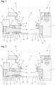
- FIGS 1 and 2 are sectional views of a tool or workpiece holder 1 with a receiving body 2 and a clamping device 3 arranged in the receiving body 2 for releasably holding a tool or workpiece in a receiving opening 4 of the receiving body 2 in a release position and a clamping position.
- the receiving body 2 contains on its upper side a plate-shaped receiving part 6 which engages into the receiving opening 4 via an annular collar 5 and which has a, for example, hypotrochoid Figure 3 recognizable inner contour 7 with one inner contact surface 8 contains.
- the receiving part 6, which is rotatably arranged in the receiving opening 5 via the ring collar 5, can be easily rotated relative to the receiving body 2 via an adjusting screw 9 designed as an eccentric screw. This allows the angular position of the receiving part 6 to be adjusted.
- the receiving body 2 with the receiving part 6 is designed to receive a clamping part 10 shown in dash-dotted lines with an outer contact surface 11 and a lower clamping pin 12.
- a conical upper surface 13 and a conical lower surface 14 are provided on the clamping pin 12.
- the receiving body 2 is part of a tool turret.
- the tool turret can be designed, for example, as a star turret with a disk-shaped receiving body 2 and several receiving openings distributed in a star shape on its outer circumference.
- the tool turret can also be designed as a disc turret with receiving openings arranged on the front side of a turret body or can have another suitable shape.
- the receiving body 2 can also be a workpiece table or another support on which a workpiece is clamped.
- the receiving opening 4 of the receiving body 2 has an inner contour adapted to the outer contour of the clamping part 10.
- the receiving opening 4 is stepped several times and contains an extended upper area 15 for receiving the ring collar 5 on the receiving part 6 and a lower area 16 with a step 17 for receiving the clamping pin 12.
- At the radial inner end of the step 17 is one Bevel 18 is provided for abutting an annular damping or sealing element 19 arranged on the clamping part 10 when the clamping part 10 is inserted into the receiving opening 4.
- the two clamping elements 20 and 21 acting on opposite sides of the clamping pin 12 can be made from one in Figure 1 shown release position in the direction of the central axis 23 towards one another in an in Figure 2
- the clamping position shown can be moved or moved from this clamping position back into the release position by moving the clamping elements 20 and 21 apart.
- the two clamping elements 20 and 21 have mutually facing ring segment-shaped clamping areas 25 and 26 with conical lower clamping surfaces 27 and 28 for contact with the conical upper surface 13 of the clamping pin 12.
- actuating element 22 is designed as a clamping screw with a cylindrical screw head 29, a first thread 30 designed as a left-hand thread on a rear shaft part 31 and a second thread 32 designed as a right-hand thread on a slimmer front shaft part 33.
- the screw head 25 there is an annular groove 34 for receiving an in Figure 1 recognizable elastic ring 35 is provided. Via the elastic ring 35, the screw-shaped actuating element 22 is secured against falling out in a bore 36 of a side part 37 which is firmly connected to the receiving body 2, but is guided in an axially movable manner.
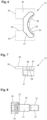
- the slide-shaped first clamping element 20 contains a part guided in the receiving body 2 on one side of the receiving opening 4 with the ring segment-shaped clamping area 25 and a part arranged in the receiving body 2 on the other side of the receiving opening 4 with a recess 38 for receiving the second clamping element 21
- the recess 38 is arranged between the ring segment-shaped clamping area 25 on one side of the first clamping element 20 and a crossbar 39 on the other side of the first clamping element 20.
- the crossbar 39 there is a thread 32 belonging to the second thread 32 of the helical actuating element 22 Threaded hole 40 provided.
- the first clamping element 20 has a downwardly offset upper surface 41 with a projection 42 on the crossbar 39.
- an opening 43 which is circular in plan view, is provided for receiving the clamping pin 12 of the clamping part 10.
- the opening 43 is designed as a through opening. This means that tools driven from below can also be clamped.
- the second clamping element 21 shown in a bottom view contains a plate-shaped upper part 46 and a block-shaped lower part 47.
- the plate-shaped upper part 46 is intended to rest on the upper surface 38 and the lower part 47 is intended to engage in the recess 39 of the first clamping element 20.
- a threaded hole 48 for receiving the first thread on the actuating element 22 is arranged in the lower part 47.
- the ring segment-shaped clamping area 26 with the conical lower clamping surfaces 28 and on the other side a recess 49 for receiving the projection 42 on the first clamping element 20 are provided.
- the second clamping element On the side of the recess 49, the second clamping element has a lateral stop surface 50 on its plate-shaped upper part 46 for contact with an in Figure 1 recognizable inner contact surface 51 of the side part 37 which is fixedly arranged on the receiving body 2.
- the two clamping elements 20 and 21 are designed such that they enclose the clamping pin 12 of the clamping part 10 from both sides.
- the two diametrically opposite clamping areas 25 and 26 are designed as ring segments. This means that good clamping and retraction force can be achieved.
- the clamping elements 20 and 21 can be moved between the in Figure 1 shown release position and in the Figure 2 shifted to the clamping position shown.
- the actuating element 22 is rotated to the right in the release position of FIG. 2, the two clamping elements 20 and 21 are moved together via the screw-shaped actuating element 22 and pulled against the clamping pin 12 of the clamping part 10.
- the clamping part 10 is drawn into the receiving opening 4.
- the clamping elements 20 and 21 can align themselves due to the axial movement possibility of the actuating element 12, so that undesirable tilting movements or inclinations of the tools or workpieces are avoided.
- the two clamping elements 20 and 21 In the clamping position, the two clamping elements 20 and 21 have no support on the receiving body 2, which means that the creation of tilting moments can be avoided.
Landscapes
- Engineering & Computer Science (AREA)
- Mechanical Engineering (AREA)
- Jigs For Machine Tools (AREA)
- Gripping On Spindles (AREA)
- Cutting Tools, Boring Holders, And Turrets (AREA)
Description
- Die Erfindung betrifft eine Werkzeug- oder Werkstückaufnahme nach dem Oberbegriff des Patentanspruchs 1.
- Aus der
DE 10 04 889 B ist eine gattungsgemäße Werkzeugaufnahme bekannt. Dort sind in einem Aufnahmekörper zwei gegeneinander und quer zur Mittelachse einer Aufnahmeöffnung verschiebbare Keilnocken angeordnet. Die Keilnocken sind durch eine als Doppelendschraube ausgebildete Schraube gegeneinander verstellbar. An den beiden Keilnocken sind Spannflächen zum Einziehen eines Werkzeugs über einen Einzugsbolzen vorgesehen. Die beiden Keilnocken weisen auch Ausdruckflächen auf, über welche das Werkzeug beim Auseinanderfahren der beiden Keilnocken ausgestoßen werden kann. - Aus der
DE 10 2014 102 082 A1 ist eine als Werkzeugrevolver ausgebildete Werkzeugaufnahme mit einem Aufnahmekörper und einer Spannvorrichtung zum Spannen eines Werkzeugs in einer Aufnahmeöffnung des Aufnahmekörpers bekannt. Dort enthält die Spannvorrichtung zwei durch ein gemeinsames Betätigungselement quer zu einer Mittelachse der Aufnahmeöffnung gegeneinander verschiebbare Spannelemente. Die Spannelemente sind nicht nur gegeneinander, sondern auch in dem Aufnahmekörper verschiebbar, wodurch selbst bei ungenauen Aufnahmen oder Verschmutzungen eine genaue und zentrische Spannung erreicht werden. Unerwünschte Kippbewegungen oder Schrägstellungen der Werkzeuge oder Werkstücke sind vermeidbar. Allerdings werden die Werkzeuge mit einer relativ hohen Kraft in die üblicherweise konischen Aufnahmeöffnungen des Revolverkörpers eingezogen, so dass sich Probleme bei der Werkzeugentnahme ergeben können. - Aufgabe der Erfindung ist es, eine Werkzeug- oder Werkstückaufnahme der eingangs genannten Art zu schaffen, die auch eine vereinfachte Entnahme eines Werkzeugs oder Werkstücks ermöglicht.
- Diese Aufgabe wird durch eine Werkzeug- oder Werkstückaufnahme mit den Merkmalen des Anspruchs 1 gelöst. Zweckmäßige Weiterbildungen und vorteilhafte Ausgestaltungen der Erfindung sind in den Unteransprüchen angegeben.
- Bei der erfindungsgemäßen Werkzeug- oder Werkstückaufnahme weist die Spannvorrichtung ein in einer Aufnahme eines Aufnahmekörpers quer zu einer Mittelachse einer Aufnahmeöffnung verschiebbares erstes Spannelement und ein mittels eines Bedienelements gegenüber dem ersten Spannelement quer zur Mittelachse der Aufnahmeöffnung verschiebbares zweites Spannelement mit konischen Spannflächen an den beiden Spannelementen zum Einziehen des Werkzeugs oder Werkstücks in die Aufnahmeöffnung auf. An dem ersten Spannelement ist eine Ausdrückeinrichtung zum Ausdrücken des Werkzeugs oder Werkstücks aus der Aufnahmeöffnung bei der Bewegung der Spannelemente in eine Lösestellung vorgesehen. Die Ausdrückeinrichtung weist an der Unterseite des ersten Spannelements angeordnete Ausdrückelemente mit einer konischen oberen Ausdrückfläche auf. Die konische untere Spannfläche des ersten Spannelements ist auf der einen Seite einer Öffnung im ersten Spannelement (20) und die Ausdrückelemente sind auf der gegenüberliegenden anderen Seite der Öffnung am ersten Spannelement angeordnet. Bei der Bewegung der Spannelemente in die Lösestellung wird über die Ausdrückeinrichtung das in der Aufnahmeöffnung angeordnete Werkzeug oder Werkstück aus der Aufnahmeöffnung herausgedrückt, wodurch ein Festklemmen der Werkzeuge oder Werkstücke vermieden und eine Entnahme erleichtert werden kann.
- Vorzugsweise ist die konische untere Spannfläche des ersten Spannelements an der Unterseite eines ringsegmentförmigen Spannbereichs des ersten Spannelements angeordnet.
- In einer weiteren vorteilhaften Ausgestaltung weist das erste Spannelement eine Vertiefung zur Aufnahme des zweiten Spannelements auf. In der Vertiefung kann das zweite Spannelement verschiebbar geführt sein.
- Das zweite Spannelement kann ein plattenförmiges Oberteil und ein blockförmiges Unterteil enthalten. Die konische untere Spannfläche des zweiten Spannelements kann an einem ringsegmentförmigen Spannbereich auf der einen Seite des plattenförmigen Oberteils angeordnet sein. Auf der anderen Seite des plattenförmigen Oberteils kann eine Aussparung zur Aufnahme eines Vorsprungs am ersten Spannelement vorgesehen sein.
- Das zweite Spannelement weist zweckmäßigerweise eine seitliche Anschlagfläche zur Anlage an einer inneren Anlagefläche eines am Aufnahmekörper fest angeordneten Seitenteils oder eines anderen gegenüber dem Aufnahmekörper festen Widerlagers auf.
- In einer besonders zweckmäßigen Ausführung kann das Betätigungselement zur Verstellung der beiden Spannelemente als Spannschraube mit einem als Rechtsgewinde ausgebildeten ersten Gewinde und einem als Linksgewinde ausgebildeten zweiten Gewinde ausgebildet sein. Durch Drehung des Betätigungselements können so die beiden Spannelemente gleichzeitig zusammen- oder auseinanderbewegt werden. Das Betätigungselement kann aber auch eine Spannschraube mit einem einzelnen Gewinde sein. Die Spannschraube kann dann über das Gewinde in einer entsprechenden Gewindebohrung im ersten Spannelement drehbar angeordnet und z.B. über einen in das zweite Spannelement formschlüssig eingreifenden endseitigen Zapfen drehbar und axial gesichert mit dem zweiten Spannelement verbunden sein.
- Die beiden gegeneinander verschiebbaren Spannelemente sind in dem Aufnahmekörper innerhalb eines vorgegebenen Bereichs beweglich, wodurch sich die beiden Spannelemente gegenüber dem Spannteil selbsttätig ausrichten können. Dadurch kann auch bei eventuellen Versetzungen zwischen dem Aufnahmekörper und dem Spannteil möglichst genaue Spannung erreicht werden. Unerwünschte Kippbewegungen oder Schrägstellungen der Spannteile sind außerdem vermeidbar.
- Die beiden Spannelemente sind vorzugsweise derart ausgebildet, dass sie einen Spannzapfen eines Spannteils von zwei Seiten umschließen. In einer besonders für angetriebene Werkzeuge geeigneten Ausführung kann das erste Spannelement eine durchgehende Öffnung aufweisen. Dadurch können z.B. auch von unten angetriebene gespannt werden.
- Die Aufnahmeöffnung des Aufnahmekörpers kann eine Einheitskontur zur Aufnahme unterschiedlicher Werkzeuge, Werkzeughalter, Werkstücke oder entsprechender Adapter aufweisen. In die Aufnahmeöffnung des Aufnahmekörpers kann auch ein Aufnahmeteil mit einer spezifischen Innenkontur eingesetzt sein. Dadurch kann die Werkzeug- oder Werkstückaufnahme einfach an unterschiedliche Bedürfnisse angepasst werden.
- Weitere Besonderheiten und Vorzüge der Erfindung ergeben sich aus der folgenden Beschreibung bevorzugter Ausführungsbeispiele anhand der Zeichnung. Es zeigen:
- Figur 1
- eine Schnittansicht einer Werkzeug- oder Werkstückaufnahme mit einem Aufnahmekörper und einer im Aufnahmekörper angeordneten Spannvorrichtung in einer Lösestellung;
- Figur 2
- eine Schnittansicht einer Werkzeug- oder Werkstückaufnahme mit einem Aufnahmekörper und einer im Aufnahmekörper angeordneten Spannvorrichtung in einer Spannstellung;
- Figur 3
- ein plattenförmiges Aufnahmeteil der in den
Figuren 1 und 2 gezeigten Werkzeug- oder Werkstückaufnahme in einer Draufsicht; - Figur 4
- ein erstes Spannelement der in
Figur 1 gezeigten Werkzeug- oder Werkstückaufnahme in einer Draufsicht; - Figur 5
- das erste Spannelement in einer Schnittansicht;
- Figur 6
- ein zweites Spannelement der in
Figur 1 gezeigten Werkzeug- oder Werkstückaufnahme in einer Unteransicht; - Figur 7
- das zweite Spannelement in einer Schnittansicht und
- Figur 8
- ein schraubenförmiges Betätigungselement der in
Figur 1 gezeigten Werkzeug- oder Werkstückaufnahme. - In den
Figuren 1 und 2 sind Schnittansichten einer Werkzeug- oder Werkstückaufnahme 1 mit einem Aufnahmekörper 2 und einer im Aufnahmekörper 2 angeordneten Spannvorrichtung 3 zur lösbaren Halterung eines Werkzeugs oder Werkstücks in einer Aufnahmeöffnung 4 des Aufnahmekörpers 2 in einer Lösestellung und einer Spannstellung gezeigt. In der dargestellten Ausführung enthält der Aufnahmekörper 2 an seiner Oberseite ein über einen Ringbund 5 in die Aufnahmeöffnung 4 eingreifendes plattenförmiges Aufnahmeteil 6, das eine z.B. als Hypotrochoid ausgebildete, inFigur 3 erkennbare Innenkontur 7 mit einer inneren Anlagefläche 8 enthält. Selbstverständlich sind auch andere Aufnahmeteile mit anderen Innenkonturen einsetzbar. Über eine als Exzenterschraube ausgebildete Stellschraube 9 kann das in der Aufnahmeöffnung 5 über den Ringbund 5 drehbar angeordnete Aufnahmeteil 6 gegenüber dem Aufnahmekörper 2 leicht gedreht werden. Dadurch kann die Winkellage des Aufnahmeteils 6 justiert werden. - Der Aufnahmekörper 2 mit dem Aufnahmeteil 6 ist zur Aufnahme eines strichpunktiert dargestellten Spannteils 10 mit einer äußeren Anlagefläche 11 und einem unteren Spannzapfen 12 ausgebildet. An dem Spannzapfen 12 sind eine konische obere Fläche 13 und eine konische untere Fläche 14 vorgesehen. Über das z.B. als Werkzeug- oder Werkstückhalter oder unmittelbar als Teil eines Werkzeugs oder Werkstücks ausgeführte Spannteil 10 kann ein Werkzeug oder auch ein Werkstück durch die Spannvorrichtung 3 positionsgenau am Aufnahmekörper 2 fixiert werden. Der Aufnahmekörper 2 ist in der gezeigten Ausführung ein Teil eines Werkzeugrevolvers. Der Werkzeugrevolver kann z.B. als Sternrevolver mit einem scheibenförmigen Aufnahmekörper 2 und mehreren an dessen Außenumfang sternförmig verteilten Aufnahmeöffnungen ausgebildet sein. Der Werkzeugrevolver kann aber auch als Scheibenrevolver mit an der Stirnseite eines Revolverkörpers angeordneten Aufnahmeöffnungen ausgeführt sein oder kann eine andere geeignete Form ausweisen. Der Aufnahmekörper 2 kann außerdem auch ein Werkstücktisch oder eine andere Auflage sein, auf denen ein Werkstück gespannt wird.
- Die Aufnahmeöffnung 4 des Aufnahmekörpers 2 weist eine an die Außenkontur des Spannteils 10 angepasste Innenkontur auf. Bei der gezeigten Ausführung ist die Aufnahmeöffnung 4 mehrfach abgestuft und enthält einen erweiterten oberen Bereich 15 zur Aufnahme des Ringbunds 5 am Aufnahmeteil 6 sowie einen unteren Bereich 16 mit einer Abstufung 17 zur Aufnahme des Spannzapfens 12. An dem radialen inneren Ende der Abstufung 17 ist eine Abschrägung 18 zur Anlage eines am Spannteil 10 angeordneten ringförmigen Dämpfungs- oder Dichtelements 19 beim Einsetzen des Spannteils 10 in die Aufnahmeöffnung 4 vorgesehen.
- Die Spannvorrichtung 3 umfasst zwei gegeneinander bewegbare Spannelemente 20 und 21, die durch ein gemeinsames Betätigungselement 22 in entgegengesetzten Richtungen quer zu einer Mittelachse 23 der Aufnahmeöffnung 4 verschiebbar und zum beidseitigen Umgreifen des Spannzapfens 12 ausgebildet sind. In der gezeigten Ausführung enthält die Spannvorrichtung 3 ein innerhalb einer entsprechenden Aufnahme 24 des Aufnahmekörpers 2 quer zur Mittelachse 23 der Aufnahmeöffnung 4 verschiebbares erstes schieberförmiges Spannelement 20 und ein gegenüber dem ersten Spannelement 20 verschiebbares zweites schieberförmiges Spannelement 21, die durch Drehung des hier als Spannschraube mit einen Rechts- und Linksgewinde ausgebildeten Betätigungselements 22 zusammen- oder auseinanderbewegt werden können.
- Durch Drehung des als Spannschraube ausgebildeten Betätigungselements 22 können die beiden an gegenüberliegenden Seiten des Spannzapfens 12 angreifenden Spannelemente 20 und 21 aus einer in
Figur 1 gezeigten Lösestellung in Richtung der Mittelachse 23 aufeinander zu in eine inFigur 2 gezeigte Spannstellung verschoben bzw. aus dieser Spannstellung durch Auseinanderfahren der Spannelemente 20 und 21 wieder in die Lösestellung bewegt werden. Die beiden Spannelemente 20 und 21 weisen einander zugewandte ringsegmentförmige Spannbereiche 25 bzw. 26 mit konischen unteren Spannflächen 27 bzw. 28 zur Anlage an der konischen oberen Fläche 13 des Spannzapfens 12 auf. - Das in
Figur 8 gesondert dargestellte Betätigungselement 22 ist als Spannschraube mit einem zylindrischen Schraubenkopf 29, einem als Linksgewinde ausgeführten ersten Gewinde 30 auf einem hinteren Schaftteil 31 und einem als Rechtsgewinde ausgebildeten zweiten Gewinde 32 auf einem schlankeren vorderen Schaftteil 33 ausgeführt. In dem Schraubenkopf 25 ist eine Ringnut 34 zur Aufnahme eines inFigur 1 erkennbaren elastischen Rings 35 vorgesehen. Über den elastischen Ring 35 ist das schraubenförmige Betätigungselement 22 in einer Bohrung 36 eines mit dem Aufnahmekörper 2 fest verbundenen Seitenteils 37 gegen Herausfallen gesichert aber axial beweglich geführt. - Wie aus den
Figuren 4 und 5 hervorgeht, enthält das schieberförmige erste Spannelement 20 einen im Aufnahmekörper 2 auf der einen Seite der Aufnahmeöffnung 4 geführten Teil mit dem ringsegmentförmigen Spannbereich 25 und einen im Aufnahmekörper 2 auf der anderen Seite der Aufnahmeöffnung 4 angeordneten Teil mit einer Vertiefung 38 zur Aufnahme des zweiten Spannelements 21. Die Vertiefung 38 ist zwischen dem ringsegmentförmigen Spannbereich 25 auf der einen Seite des ersten Spannelements 20 und einem Quersteg 39 auf der anderen Seite des ersten Spannelements 20 angeordnet. In dem Quersteg 39 ist eine zu dem zweiten Gewinde 32 des schraubenförmigen Betätigungselements 22 gehörende Gewindebohrung 40 vorgesehen. An der Oberseite weist das erste Spannelement 20 eine nach unten versetzte obere Fläche 41 mit einem Vorsprung 42 am Quersteg 39 auf. In dem ersten Spannelement 20 ist eine in der Draufsicht kreisrunde Öffnung 43 zur Aufnahme des Spannzapfens 12 des Spannteils 10 vorgesehen. In der gezeigten Ausführung ist die Öffnung 43 als Durchgangsöffnung ausgeführt. Dadurch können z.B. auch von unten angetriebene Werkzeuge gespannt werden. - Das erste Spannelement 20 enthält ferner eine Ausdrückeinrichtung, die an der Unterseite des ersten Spannelements 20 angeordnete Ausdrückelemente 44 mit einer konischen oberen Ausdrückfläche 45 zur Anlage an der konischen unteren Fläche 14 des Spannzapfens 12 umfasst. In der gezeigten Ausführung sind die Ausdrückelemente 44 als gegenüber der Öffnung 43 nach innen vorstehende, ringsegmentförmige Ansätze ausgebildet. Durch die Ausdrückeinrichtung kann das Spannteil 10 bei der Bewegung der Spannelemente 20 und 21 in eine Lösestellung aus der Aufnahmeöffnung 4 des Aufnahmeköpers 2 herausgedrückt und somit die Entnahme eines Werkstücks oder Werkzeugs erleichtert werden.
- In der Vertiefung 38 des ersten Spannelements 20 ist das in den
Figuren 6 und 7 gezeigte zweite Spannelement 21 verschiebbar geführt. Das inFigur 6 in einer Unteransicht gezeigte zweite Spannelement 21 enthält ein plattenförmiges Oberteil 46 und ein blockförmiges Unterteil 47. Das plattenförmige Oberteil 46 ist zur Auflage auf der oberen Fläche 38 und das Unterteil 47 zum Eingriff in die Vertiefung 39 des ersten Spannelements 20 bestimmt. In dem Unterteil 47 ist eine Gewindebohrung 48 zur Aufnahme des ersten Gewindes am Betätigungselements 22 angeordnet. Auf der einen Seite des plattenförmigen Oberteils sind der ringsegmentförmige Spannbereich 26 mit den konischen unteren Spannflächen 28 und auf der anderen Seite eine Aussparung 49 zur Aufnahme des Vorsprungs 42 am ersten Spannelement 20 vorgesehen. An der Seite der Aussparung 49 weist das zweite Spannelement an seinem plattenförmigen Oberteil 46 eine seitliche Anschlagfläche 50 zur Anlage an einer inFigur 1 erkennbaren inneren Anlagefläche 51 des am Aufnahmekörper 2 fest angeordneten Seitenteils 37 auf. - Wie aus den
Figuren 1 und 2 hervorgeht, sind die beiden Spannelemente 20 und 21 derart ausgebildet, dass sie den Spannzapfen 12 des Spannteils 10 von beiden Seiten umschließen. Die beiden diametral gegenüberliegenden Spannbereiche 25 und 26 sind als Ringsegmente ausgeführt. Dadurch ist eine gute Spann- und Einzugskraft erreichbar. - Durch Drehung des hier als Spannschraube ausgebildeten Betätigungselements 22 können die Spannelemente 20 und 21 zwischen der in
Figur 1 gezeigten Lösestellung und der in denFigur 2 gezeigten Spannstellung verschoben. Wird z.B. das Betätigungselement 22 in der Lösestellung von 2 nach rechts gedreht, werden die beiden Spannelemente 20 und 21 über das schraubenförmige Betätigungselement 22 zusammengefahren und gegen den Spannzapfen 12 des Spannteils 10 gezogen. Dabei wird das Spannteil 10 in die Aufnahmeöffnung 4 eingezogen. Selbst wenn die beiden Spannelemente 20 nicht zentriert zum Spannteil 10 sind, können sich die Spannelemente 20 und 21 durch die axiale Bewegungsmöglichkeit des Betätigungselements 12 ausrichten, so dass unerwünschte Kippbewegungen oder Schrägstellungen der Werkzeuge oder Werkstücke vermieden werden. In der Spannstellung weisen die beiden Spannelemente 20 und 21 keine Abstützung an dem Aufnahmekörper 2 auf, wodurch die Entstehung von Kippmomenten vermieden werden kann. - Wird das schraubenförmige Betätigungselement 22 dagegen bei der in
Figur 2 gezeigten Spannstellung nach links gedreht, fahren die beiden Spannelemente 20 und 21 auseinander, bis das zweite Spannelement 21 mit seiner Anschlagfläche 50 zur Anlage an der gegenüber dem Aufnahmekörper 2 festen Anlagefläche 51 gelangt. Durch weitere Drehung des Betätigungselements 22 in die Löserichtung verfährt dann das erste Spannelement 20 mit seiner Ausdrückfläche 45 unter den Spannzapfen 12, so dass das Spannteil 10 aus der Aufnahmeöffnung 4 gedrückt wird. Durch das Verfahren der beiden Spannelemente 20 und 21 kann das Spannteil 10 also nicht nur in die Aufnahmeöffnung 4 eingezogen, sondern aus dieser auch wieder herausgedrückt werden. -
- 1
- Werkzeug- oder Werkstückaufnahme
- 2
- Aufnahmekörper
- 3
- Spannvorrichtung
- 4
- Aufnahmeöffnung
- 5
- Ringbund
- 6
- Aufnahmeteil
- 7
- Innenkontur
- 8
- Innere Anlagefläche
- 9
- Stellschraube
- 10
- Spannteil
- 11
- Äußere Anlagefläche
- 12
- Spannzapfen
- 13
- Konische obere Fläche
- 14
- Konische untere Fläche
- 15
- Oberer Bereich
- 16
- Unterer Bereich
- 17
- Abstufung
- 18
- Abschrägung
- 19
- Dämpfungs- oder Dichtelement
- 20
- Erstes Spannelement
- 21
- Zweites Spannelement
- 22
- Betätigungselement
- 23
- Mittelachse
- 24
- Aufnahme
- 25
- Spannbereich
- 26
- Spannbereich
- 27
- Spannfläche
- 28
- Spannfläche
- 29
- Schraubenkopf
- 30
- Erstes Gewinde
- 31
- Hinterer Schaftteil
- 32
- Zweites Gewinde
- 33
- Vorderer Schaftteil
- 34
- Ringnut
- 35
- Ring
- 36
- Bohrung
- 37
- Seitenteil
- 38
- Vertiefung
- 39
- Quersteg
- 40
- Gewindebohrung
- 41
- Obere Fläche
- 42
- Vorsprung
- 43
- Öffnung
- 44
- Ausdrückelement
- 45
- Ausdrückfläche
- 46
- Oberteil
- 47
- Unterteil
- 48
- Gewindebohrung
- 49
- Aussparung
- 50
- Anschlagfläche
- 51
- Anlagefläche
Claims (12)
- Werkzeug- oder Werkstückaufnahme (1) mit einem Aufnahmekörper (2) und einer Spannvorrichtung (3) zum Spannen eines Werkzeugs oder eines Werkstücks in einer Aufnahmeöffnung (4) des Aufnahmekörpers (2), wobei die Spannvorrichtung (3) ein in einer Aufnahme (24) des Aufnahmekörpers (2) quer zu einer Mittelachse (23) der Aufnahmeöffnung (4) verschiebbares erstes Spannelement (20) und ein mittels eines Bedienelements (22) gegenüber dem ersten Spannelement (10) quer zur Mittelachse (23) der Aufnahmeöffnung (4) verschiebbares zweites Spannelement (21) mit konischen unteren Spannflächen (27, 28) an den beiden Spannelementen (20, 21) zum Einziehen des Werkzeugs oder Werkstücks in die Aufnahmeöffnung (4) umfasst und wobei an dem ersten Spannelement (20) eine Ausdrückeinrichtung (44, 45) zum Ausdrücken des Werkzeugs oder Werkstücks aus der Aufnahmeöffnung (4) bei der Bewegung der Spannelemente (20, 21) in eine Lösestellung angeordnet ist und die Ausdrückeinrichtung (44, 45) an der Unterseite des ersten Spannelements (20) angeordnete Ausdrückelemente (44) mit einer konischen oberen Ausdrückfläche (45) umfasst, dadurch gekennzeichnet, dass die konische untere Spannfläche (27) des ersten Spannelements (20) auf der einen Seite einer Öffnung (43) im ersten Spannelement (20) und die Ausdrückelemente (44) auf der gegenüberliegenden anderen Seite der Öffnung (43) am ersten Spannelement (20) angeordnet sind.
- Werkzeug- oder Werkstückaufnahme (1) nach Anspruch 1, dadurch gekennzeichnet, dass die Ausdrückelemente (44) als gegenüber der Öffnung (43) nach innen vorstehende ringsegmentförmige Ansätze ausgebildet sind.
- Werkzeug- oder Werkstückaufnahme (1) nach Anspruch 1 oder 2, dadurch gekennzeichnet, dass die konische untere Spannfläche (27) des ersten Spannelements (20) an der Unterseite eines ringsegmentförmigen Spannbereichs (25) des ersten Spannelements (20) angeordnet ist.
- Werkzeug- oder Werkstückaufnahme (1) nach einem der Ansprüche 1 bis 3, dadurch gekennzeichnet, dass das erste Spannelement (20) eine Vertiefung (38) zur Aufnahme des zweiten Spannelements (21) enthält.
- Werkzeug- oder Werkstückaufnahme (1) nach einem der Ansprüche 1 bis 4, dadurch gekennzeichnet, dass das zweite Spannelement (21) ein plattenförmiges Oberteil (46) und ein blockförmiges Unterteil (47) enthält.
- Werkzeug- oder Werkstückaufnahme (1) nach Anspruch 5, dadurch gekennzeichnet, dass die konische untere Spannfläche (28) des zweiten Spannelements (21) an einem ringsegmentförmigen Spannbereich (26) auf der einen Seite des plattenförmigen Oberteils (46) angeordnet ist.
- Werkzeug- oder Werkstückaufnahme (1) nach Anspruch 6, dadurch gekennzeichnet, dass auf der anderen Seite des plattenförmigen Oberteils (46) eine Aussparung (49) zur Aufnahme eines Vorsprungs (42) am ersten Spannelement (20) vorgesehen ist.
- Werkzeug- oder Werkstückaufnahme (1) nach einem der Ansprüche 1 bis 7, dadurch gekennzeichnet, dass das zweite Spannelement (21) eine seitliche Anschlagfläche (50) zur Anlage an einer inneren Anlagefläche (51) eines am Aufnahmekörper (2) fest angeordneten Seitenteils (37) enthält.
- Werkzeug- oder Werkstückaufnahme (1) nach einem der Ansprüche 1 bis 8, dadurch gekennzeichnet, dass das Betätigungselement (22) als Spannschraube mit einem als Linksgewinde ausgebildeten ersten Gewinde (30) und einem als Rechtsgewinde ausgebildeten zweiten Gewinde (32) ausgebildet ist.
- Werkzeug- oder Werkstückaufnahme (1) nach einem der Ansprüche 1 bis 9, dadurch gekennzeichnet, dass in dem ersten Spannelement (20) eine Gewindebohrung (40) für das Befestigungselement (22) vorgesehen ist.
- Werkzeug- oder Werkstückaufnahme (1) nach Anspruch 10, dadurch gekennzeichnet, dass in dem zweiten Spannelement (21) eine Gewindebohrung (48) für das Befestigungselement (22) vorgesehen ist.
- Werkzeug- oder Werkstückaufnahme (1) nach einem der Ansprüche 1 bis 11, dadurch gekennzeichnet, dass die beiden Spannelemente (20, 21) derart ausgebildet sind, dass sie einen Spannzapfen (12) eines Spannteils (10) von zwei Seiten umschließen.
Applications Claiming Priority (1)
| Application Number | Priority Date | Filing Date | Title |
|---|---|---|---|
| DE102020120525.2A DE102020120525A1 (de) | 2020-08-04 | 2020-08-04 | Werkzeug- oder Werkstückaufnahme |
Publications (2)
| Publication Number | Publication Date |
|---|---|
| EP3950193A1 EP3950193A1 (de) | 2022-02-09 |
| EP3950193B1 true EP3950193B1 (de) | 2024-01-03 |
Family
ID=75252352
Family Applications (1)
| Application Number | Title | Priority Date | Filing Date |
|---|---|---|---|
| EP21165108.8A Active EP3950193B1 (de) | 2020-08-04 | 2021-03-26 | Werkzeug- oder werkstückaufnahme |
Country Status (5)
| Country | Link |
|---|---|
| US (1) | US11717941B2 (de) |
| EP (1) | EP3950193B1 (de) |
| JP (1) | JP7205936B2 (de) |
| DE (1) | DE102020120525A1 (de) |
| ES (1) | ES2973738T3 (de) |
Families Citing this family (1)
| Publication number | Priority date | Publication date | Assignee | Title |
|---|---|---|---|---|
| JP7786248B2 (ja) | 2022-02-28 | 2025-12-16 | セイコーエプソン株式会社 | 搬送装置及び印刷装置 |
Family Cites Families (15)
| Publication number | Priority date | Publication date | Assignee | Title |
|---|---|---|---|---|
| DE1004889B (de) | 1950-11-30 | 1957-03-21 | Giddings & Lewis | Vorrichtung zum Verriegeln eines Werkzeugkegels in einem Werkzeughalter |
| US2684249A (en) * | 1950-11-30 | 1954-07-20 | Giddings & Lewis | Toolhead and taper shank adapter |
| DE202005006557U1 (de) * | 2005-03-17 | 2005-07-07 | Walter Perske Gmbh | Kupplungseinrichtung |
| DE102005012869A1 (de) | 2005-03-17 | 2006-09-21 | Walter Perske Gmbh | Kupplungseinrichtung |
| TW200732083A (en) | 2006-01-30 | 2007-09-01 | Tool Internat Ag F | Clamping apparatus |
| DE102006028373B4 (de) | 2006-06-19 | 2016-01-21 | Komet Group Gmbh | Drehendes Werkzeugsystem mit einer Trennstelle zwischen zwei Teilelementen |
| ATE460250T1 (de) * | 2007-10-22 | 2010-03-15 | Erowa Ag | Spanneinrichtung mit einem spannfutter zum lösbaren fixieren eines werkstückträgers |
| DE102014102082A1 (de) | 2014-02-19 | 2015-08-20 | Ott-Jakob Spanntechnik Gmbh | Werkzeugrevolver |
| US10661449B2 (en) * | 2014-08-20 | 2020-05-26 | Ati Industrial Automation, Inc. | Safe robotic tool changer |
| US10603750B1 (en) * | 2017-04-04 | 2020-03-31 | Jergens, Inc. | Mounting system with self aligning cam system |
| JP6930895B2 (ja) * | 2017-10-30 | 2021-09-01 | ニッタ株式会社 | 自動工具交換用カップラー及び自動工具交換装置 |
| TWM573673U (zh) * | 2018-08-28 | 2019-02-01 | 周文祥 | 具簡便定位之交換裝置 |
| CA3045312C (en) * | 2018-09-09 | 2021-05-04 | Fifth Axis, Inc. | Tooling base |
| DK180331B1 (en) * | 2019-06-12 | 2020-11-26 | Triplea Robotics Aps | Tool changer |
| PL3778082T3 (pl) * | 2019-08-14 | 2022-08-22 | Smw-Autoblok Spannsysteme Gmbh | Urządzenie mocujące z punktem zerowym |
-
2020
- 2020-08-04 DE DE102020120525.2A patent/DE102020120525A1/de not_active Withdrawn
-
2021
- 2021-03-26 ES ES21165108T patent/ES2973738T3/es active Active
- 2021-03-26 EP EP21165108.8A patent/EP3950193B1/de active Active
- 2021-07-07 JP JP2021112480A patent/JP7205936B2/ja active Active
- 2021-08-02 US US17/391,116 patent/US11717941B2/en active Active
Also Published As
| Publication number | Publication date |
|---|---|
| JP7205936B2 (ja) | 2023-01-17 |
| US20220040821A1 (en) | 2022-02-10 |
| JP2022029424A (ja) | 2022-02-17 |
| ES2973738T3 (es) | 2024-06-24 |
| DE102020120525A1 (de) | 2022-02-10 |
| EP3950193A1 (de) | 2022-02-09 |
| US11717941B2 (en) | 2023-08-08 |
Similar Documents
| Publication | Publication Date | Title |
|---|---|---|
| DE3504905C2 (de) | ||
| EP3047818B1 (de) | Haltevorrichtung für ein dentales werkstück | |
| WO1990001387A1 (de) | Spannzangenfutter | |
| EP0312951A2 (de) | Spannvorrichtung | |
| DE102008040562A1 (de) | Werkzeug mit axialer Einstellbarkeit | |
| DE3835879C1 (de) | ||
| EP0490913B1 (de) | Vorrichtung zum lösbaren verbinden eines werkzeugs mit einer maschinenspindel | |
| DE3814550C1 (en) | Clamping device for clamping two machine parts releasable from one another | |
| DE1642049U (de) | Spannfutter bzw. spannkopf fuer bohrmaschinen od. dgl. | |
| DE2541123A1 (de) | Vorrichtung zum befestigen von spanabhebenden werkzeugen an maschinenspindeln | |
| DE3706123C2 (de) | ||
| EP0027282B1 (de) | Spindelverlängerung für Werkzeugmaschinen | |
| DE69308053T2 (de) | Vorrichtung für die Hauptspindel einer Werkzeugmaschine | |
| DE4123966A1 (de) | Spannvorrichtung fuer einzelwerkzeuge | |
| WO1996002346A1 (de) | Werkzeugkopf mit axial verstellbarem spannfutter | |
| DE69215905T2 (de) | Spannvorrichtung für fräser oder ähnliche, anpassbar für verschiedene haltergrössen | |
| DE102012104392A1 (de) | Werkzeughalter für ein Werkzeug zum Entgraten und Anfasen | |
| EP3950193A1 (de) | Werkzeug- oder werkstückaufnahme | |
| EP2910325B1 (de) | Werkzeugrevolver | |
| EP1660262A1 (de) | Schnittstelle eines werkzeugs | |
| EP0630307A1 (de) | Werkzeughalter für ein schneidwerkzeug. | |
| EP0038103B1 (de) | Schnellspannfutter | |
| DE102020110477A1 (de) | Vorrichtung und Verfahren zum Anschluss einer Kühldüse an eine Kühlschmiermittelzuführung | |
| DE9405935U1 (de) | Spannfutter | |
| EP0275911A1 (de) | Einrichtung zum Verbinden zweier im Verbindungsbereich im wesentlichen rotationssymmetrisch gestalteter Bauteile, insbesondere eines Werkzeugkopfes mit einem Werkzeugträger zum Einsatz an Werkzeugmaschinen |
Legal Events
| Date | Code | Title | Description |
|---|---|---|---|
| PUAI | Public reference made under article 153(3) epc to a published international application that has entered the european phase |
Free format text: ORIGINAL CODE: 0009012 |
|
| STAA | Information on the status of an ep patent application or granted ep patent |
Free format text: STATUS: THE APPLICATION HAS BEEN PUBLISHED |
|
| AK | Designated contracting states |
Kind code of ref document: A1 Designated state(s): AL AT BE BG CH CY CZ DE DK EE ES FI FR GB GR HR HU IE IS IT LI LT LU LV MC MK MT NL NO PL PT RO RS SE SI SK SM TR |
|
| STAA | Information on the status of an ep patent application or granted ep patent |
Free format text: STATUS: REQUEST FOR EXAMINATION WAS MADE |
|
| 17P | Request for examination filed |
Effective date: 20220809 |
|
| RBV | Designated contracting states (corrected) |
Designated state(s): AL AT BE BG CH CY CZ DE DK EE ES FI FR GB GR HR HU IE IS IT LI LT LU LV MC MK MT NL NO PL PT RO RS SE SI SK SM TR |
|
| GRAP | Despatch of communication of intention to grant a patent |
Free format text: ORIGINAL CODE: EPIDOSNIGR1 |
|
| STAA | Information on the status of an ep patent application or granted ep patent |
Free format text: STATUS: GRANT OF PATENT IS INTENDED |
|
| RIC1 | Information provided on ipc code assigned before grant |
Ipc: B23B 29/20 20060101ALN20230912BHEP Ipc: B23B 29/24 20060101ALI20230912BHEP Ipc: B23B 31/00 20060101ALI20230912BHEP Ipc: B23B 29/04 20060101ALI20230912BHEP Ipc: B23B 31/07 20060101ALI20230912BHEP Ipc: B23B 31/107 20060101AFI20230912BHEP |
|
| RIC1 | Information provided on ipc code assigned before grant |
Ipc: B23B 29/20 20060101ALN20230926BHEP Ipc: B23B 29/24 20060101ALI20230926BHEP Ipc: B23B 31/00 20060101ALI20230926BHEP Ipc: B23B 29/04 20060101ALI20230926BHEP Ipc: B23B 31/07 20060101ALI20230926BHEP Ipc: B23B 31/107 20060101AFI20230926BHEP |
|
| INTG | Intention to grant announced |
Effective date: 20231016 |
|
| GRAS | Grant fee paid |
Free format text: ORIGINAL CODE: EPIDOSNIGR3 |
|
| GRAA | (expected) grant |
Free format text: ORIGINAL CODE: 0009210 |
|
| STAA | Information on the status of an ep patent application or granted ep patent |
Free format text: STATUS: THE PATENT HAS BEEN GRANTED |
|
| AK | Designated contracting states |
Kind code of ref document: B1 Designated state(s): AL AT BE BG CH CY CZ DE DK EE ES FI FR GB GR HR HU IE IS IT LI LT LU LV MC MK MT NL NO PL PT RO RS SE SI SK SM TR |
|
| REG | Reference to a national code |
Ref country code: GB Ref legal event code: FG4D Free format text: NOT ENGLISH |
|
| REG | Reference to a national code |
Ref country code: CH Ref legal event code: EP |
|
| REG | Reference to a national code |
Ref country code: DE Ref legal event code: R096 Ref document number: 502021002320 Country of ref document: DE |
|
| REG | Reference to a national code |
Ref country code: IE Ref legal event code: FG4D Free format text: LANGUAGE OF EP DOCUMENT: GERMAN |
|
| REG | Reference to a national code |
Ref country code: LT Ref legal event code: MG9D |
|
| REG | Reference to a national code |
Ref country code: NL Ref legal event code: MP Effective date: 20240103 |
|
| REG | Reference to a national code |
Ref country code: ES Ref legal event code: FG2A Ref document number: 2973738 Country of ref document: ES Kind code of ref document: T3 Effective date: 20240624 |
|
| PG25 | Lapsed in a contracting state [announced via postgrant information from national office to epo] |
Ref country code: NL Free format text: LAPSE BECAUSE OF FAILURE TO SUBMIT A TRANSLATION OF THE DESCRIPTION OR TO PAY THE FEE WITHIN THE PRESCRIBED TIME-LIMIT Effective date: 20240103 |
|
| PG25 | Lapsed in a contracting state [announced via postgrant information from national office to epo] |
Ref country code: NL Free format text: LAPSE BECAUSE OF FAILURE TO SUBMIT A TRANSLATION OF THE DESCRIPTION OR TO PAY THE FEE WITHIN THE PRESCRIBED TIME-LIMIT Effective date: 20240103 |
|
| PG25 | Lapsed in a contracting state [announced via postgrant information from national office to epo] |
Ref country code: IS Free format text: LAPSE BECAUSE OF FAILURE TO SUBMIT A TRANSLATION OF THE DESCRIPTION OR TO PAY THE FEE WITHIN THE PRESCRIBED TIME-LIMIT Effective date: 20240503 |
|
| PG25 | Lapsed in a contracting state [announced via postgrant information from national office to epo] |
Ref country code: LT Free format text: LAPSE BECAUSE OF FAILURE TO SUBMIT A TRANSLATION OF THE DESCRIPTION OR TO PAY THE FEE WITHIN THE PRESCRIBED TIME-LIMIT Effective date: 20240103 |
|
| PG25 | Lapsed in a contracting state [announced via postgrant information from national office to epo] |
Ref country code: GR Free format text: LAPSE BECAUSE OF FAILURE TO SUBMIT A TRANSLATION OF THE DESCRIPTION OR TO PAY THE FEE WITHIN THE PRESCRIBED TIME-LIMIT Effective date: 20240404 |
|
| PG25 | Lapsed in a contracting state [announced via postgrant information from national office to epo] |
Ref country code: RS Free format text: LAPSE BECAUSE OF FAILURE TO SUBMIT A TRANSLATION OF THE DESCRIPTION OR TO PAY THE FEE WITHIN THE PRESCRIBED TIME-LIMIT Effective date: 20240403 Ref country code: HR Free format text: LAPSE BECAUSE OF FAILURE TO SUBMIT A TRANSLATION OF THE DESCRIPTION OR TO PAY THE FEE WITHIN THE PRESCRIBED TIME-LIMIT Effective date: 20240103 |
|
| PG25 | Lapsed in a contracting state [announced via postgrant information from national office to epo] |
Ref country code: CZ Free format text: LAPSE BECAUSE OF FAILURE TO SUBMIT A TRANSLATION OF THE DESCRIPTION OR TO PAY THE FEE WITHIN THE PRESCRIBED TIME-LIMIT Effective date: 20240103 |
|
| PG25 | Lapsed in a contracting state [announced via postgrant information from national office to epo] |
Ref country code: RS Free format text: LAPSE BECAUSE OF FAILURE TO SUBMIT A TRANSLATION OF THE DESCRIPTION OR TO PAY THE FEE WITHIN THE PRESCRIBED TIME-LIMIT Effective date: 20240403 Ref country code: NO Free format text: LAPSE BECAUSE OF FAILURE TO SUBMIT A TRANSLATION OF THE DESCRIPTION OR TO PAY THE FEE WITHIN THE PRESCRIBED TIME-LIMIT Effective date: 20240403 Ref country code: LT Free format text: LAPSE BECAUSE OF FAILURE TO SUBMIT A TRANSLATION OF THE DESCRIPTION OR TO PAY THE FEE WITHIN THE PRESCRIBED TIME-LIMIT Effective date: 20240103 Ref country code: IS Free format text: LAPSE BECAUSE OF FAILURE TO SUBMIT A TRANSLATION OF THE DESCRIPTION OR TO PAY THE FEE WITHIN THE PRESCRIBED TIME-LIMIT Effective date: 20240503 Ref country code: HR Free format text: LAPSE BECAUSE OF FAILURE TO SUBMIT A TRANSLATION OF THE DESCRIPTION OR TO PAY THE FEE WITHIN THE PRESCRIBED TIME-LIMIT Effective date: 20240103 Ref country code: GR Free format text: LAPSE BECAUSE OF FAILURE TO SUBMIT A TRANSLATION OF THE DESCRIPTION OR TO PAY THE FEE WITHIN THE PRESCRIBED TIME-LIMIT Effective date: 20240404 Ref country code: CZ Free format text: LAPSE BECAUSE OF FAILURE TO SUBMIT A TRANSLATION OF THE DESCRIPTION OR TO PAY THE FEE WITHIN THE PRESCRIBED TIME-LIMIT Effective date: 20240103 Ref country code: BG Free format text: LAPSE BECAUSE OF FAILURE TO SUBMIT A TRANSLATION OF THE DESCRIPTION OR TO PAY THE FEE WITHIN THE PRESCRIBED TIME-LIMIT Effective date: 20240103 |
|
| PG25 | Lapsed in a contracting state [announced via postgrant information from national office to epo] |
Ref country code: PL Free format text: LAPSE BECAUSE OF FAILURE TO SUBMIT A TRANSLATION OF THE DESCRIPTION OR TO PAY THE FEE WITHIN THE PRESCRIBED TIME-LIMIT Effective date: 20240103 Ref country code: PT Free format text: LAPSE BECAUSE OF FAILURE TO SUBMIT A TRANSLATION OF THE DESCRIPTION OR TO PAY THE FEE WITHIN THE PRESCRIBED TIME-LIMIT Effective date: 20240503 |
|
| PG25 | Lapsed in a contracting state [announced via postgrant information from national office to epo] |
Ref country code: SE Free format text: LAPSE BECAUSE OF FAILURE TO SUBMIT A TRANSLATION OF THE DESCRIPTION OR TO PAY THE FEE WITHIN THE PRESCRIBED TIME-LIMIT Effective date: 20240103 Ref country code: PT Free format text: LAPSE BECAUSE OF FAILURE TO SUBMIT A TRANSLATION OF THE DESCRIPTION OR TO PAY THE FEE WITHIN THE PRESCRIBED TIME-LIMIT Effective date: 20240503 Ref country code: PL Free format text: LAPSE BECAUSE OF FAILURE TO SUBMIT A TRANSLATION OF THE DESCRIPTION OR TO PAY THE FEE WITHIN THE PRESCRIBED TIME-LIMIT Effective date: 20240103 Ref country code: LV Free format text: LAPSE BECAUSE OF FAILURE TO SUBMIT A TRANSLATION OF THE DESCRIPTION OR TO PAY THE FEE WITHIN THE PRESCRIBED TIME-LIMIT Effective date: 20240103 |
|
| REG | Reference to a national code |
Ref country code: DE Ref legal event code: R097 Ref document number: 502021002320 Country of ref document: DE |
|
| PG25 | Lapsed in a contracting state [announced via postgrant information from national office to epo] |
Ref country code: DK Free format text: LAPSE BECAUSE OF FAILURE TO SUBMIT A TRANSLATION OF THE DESCRIPTION OR TO PAY THE FEE WITHIN THE PRESCRIBED TIME-LIMIT Effective date: 20240103 |
|
| PG25 | Lapsed in a contracting state [announced via postgrant information from national office to epo] |
Ref country code: SM Free format text: LAPSE BECAUSE OF FAILURE TO SUBMIT A TRANSLATION OF THE DESCRIPTION OR TO PAY THE FEE WITHIN THE PRESCRIBED TIME-LIMIT Effective date: 20240103 |
|
| PG25 | Lapsed in a contracting state [announced via postgrant information from national office to epo] |
Ref country code: EE Free format text: LAPSE BECAUSE OF FAILURE TO SUBMIT A TRANSLATION OF THE DESCRIPTION OR TO PAY THE FEE WITHIN THE PRESCRIBED TIME-LIMIT Effective date: 20240103 |
|
| PG25 | Lapsed in a contracting state [announced via postgrant information from national office to epo] |
Ref country code: SK Free format text: LAPSE BECAUSE OF FAILURE TO SUBMIT A TRANSLATION OF THE DESCRIPTION OR TO PAY THE FEE WITHIN THE PRESCRIBED TIME-LIMIT Effective date: 20240103 |
|
| PG25 | Lapsed in a contracting state [announced via postgrant information from national office to epo] |
Ref country code: SM Free format text: LAPSE BECAUSE OF FAILURE TO SUBMIT A TRANSLATION OF THE DESCRIPTION OR TO PAY THE FEE WITHIN THE PRESCRIBED TIME-LIMIT Effective date: 20240103 Ref country code: SK Free format text: LAPSE BECAUSE OF FAILURE TO SUBMIT A TRANSLATION OF THE DESCRIPTION OR TO PAY THE FEE WITHIN THE PRESCRIBED TIME-LIMIT Effective date: 20240103 Ref country code: RO Free format text: LAPSE BECAUSE OF FAILURE TO SUBMIT A TRANSLATION OF THE DESCRIPTION OR TO PAY THE FEE WITHIN THE PRESCRIBED TIME-LIMIT Effective date: 20240103 Ref country code: EE Free format text: LAPSE BECAUSE OF FAILURE TO SUBMIT A TRANSLATION OF THE DESCRIPTION OR TO PAY THE FEE WITHIN THE PRESCRIBED TIME-LIMIT Effective date: 20240103 Ref country code: DK Free format text: LAPSE BECAUSE OF FAILURE TO SUBMIT A TRANSLATION OF THE DESCRIPTION OR TO PAY THE FEE WITHIN THE PRESCRIBED TIME-LIMIT Effective date: 20240103 |
|
| PLBE | No opposition filed within time limit |
Free format text: ORIGINAL CODE: 0009261 |
|
| STAA | Information on the status of an ep patent application or granted ep patent |
Free format text: STATUS: NO OPPOSITION FILED WITHIN TIME LIMIT |
|
| PG25 | Lapsed in a contracting state [announced via postgrant information from national office to epo] |
Ref country code: LU Free format text: LAPSE BECAUSE OF NON-PAYMENT OF DUE FEES Effective date: 20240326 |
|
| PG25 | Lapsed in a contracting state [announced via postgrant information from national office to epo] |
Ref country code: MC Free format text: LAPSE BECAUSE OF FAILURE TO SUBMIT A TRANSLATION OF THE DESCRIPTION OR TO PAY THE FEE WITHIN THE PRESCRIBED TIME-LIMIT Effective date: 20240103 |
|
| PG25 | Lapsed in a contracting state [announced via postgrant information from national office to epo] |
Ref country code: MC Free format text: LAPSE BECAUSE OF FAILURE TO SUBMIT A TRANSLATION OF THE DESCRIPTION OR TO PAY THE FEE WITHIN THE PRESCRIBED TIME-LIMIT Effective date: 20240103 Ref country code: LU Free format text: LAPSE BECAUSE OF NON-PAYMENT OF DUE FEES Effective date: 20240326 |
|
| 26N | No opposition filed |
Effective date: 20241007 |
|
| REG | Reference to a national code |
Ref country code: BE Ref legal event code: MM Effective date: 20240331 |
|
| PG25 | Lapsed in a contracting state [announced via postgrant information from national office to epo] |
Ref country code: BE Free format text: LAPSE BECAUSE OF NON-PAYMENT OF DUE FEES Effective date: 20240331 |
|
| PG25 | Lapsed in a contracting state [announced via postgrant information from national office to epo] |
Ref country code: IE Free format text: LAPSE BECAUSE OF NON-PAYMENT OF DUE FEES Effective date: 20240326 |
|
| PG25 | Lapsed in a contracting state [announced via postgrant information from national office to epo] |
Ref country code: IE Free format text: LAPSE BECAUSE OF NON-PAYMENT OF DUE FEES Effective date: 20240326 Ref country code: BE Free format text: LAPSE BECAUSE OF NON-PAYMENT OF DUE FEES Effective date: 20240331 |
|
| PG25 | Lapsed in a contracting state [announced via postgrant information from national office to epo] |
Ref country code: SI Free format text: LAPSE BECAUSE OF FAILURE TO SUBMIT A TRANSLATION OF THE DESCRIPTION OR TO PAY THE FEE WITHIN THE PRESCRIBED TIME-LIMIT Effective date: 20240103 |
|
| PGFP | Annual fee paid to national office [announced via postgrant information from national office to epo] |
Ref country code: AT Payment date: 20250417 Year of fee payment: 5 |
|
| PGFP | Annual fee paid to national office [announced via postgrant information from national office to epo] |
Ref country code: DE Payment date: 20250415 Year of fee payment: 5 |
|
| PGFP | Annual fee paid to national office [announced via postgrant information from national office to epo] |
Ref country code: ES Payment date: 20250416 Year of fee payment: 5 |
|
| PGFP | Annual fee paid to national office [announced via postgrant information from national office to epo] |
Ref country code: IT Payment date: 20250331 Year of fee payment: 5 |
|
| PGFP | Annual fee paid to national office [announced via postgrant information from national office to epo] |
Ref country code: CH Payment date: 20250401 Year of fee payment: 5 |
|
| PG25 | Lapsed in a contracting state [announced via postgrant information from national office to epo] |
Ref country code: CY Free format text: LAPSE BECAUSE OF FAILURE TO SUBMIT A TRANSLATION OF THE DESCRIPTION OR TO PAY THE FEE WITHIN THE PRESCRIBED TIME-LIMIT; INVALID AB INITIO Effective date: 20210326 |
|
| PG25 | Lapsed in a contracting state [announced via postgrant information from national office to epo] |
Ref country code: HU Free format text: LAPSE BECAUSE OF FAILURE TO SUBMIT A TRANSLATION OF THE DESCRIPTION OR TO PAY THE FEE WITHIN THE PRESCRIBED TIME-LIMIT; INVALID AB INITIO Effective date: 20210326 |
|
| PG25 | Lapsed in a contracting state [announced via postgrant information from national office to epo] |
Ref country code: FI Free format text: LAPSE BECAUSE OF FAILURE TO SUBMIT A TRANSLATION OF THE DESCRIPTION OR TO PAY THE FEE WITHIN THE PRESCRIBED TIME-LIMIT Effective date: 20240103 |
|
| GBPC | Gb: european patent ceased through non-payment of renewal fee |
Effective date: 20250326 |
|
| PG25 | Lapsed in a contracting state [announced via postgrant information from national office to epo] |
Ref country code: TR Free format text: LAPSE BECAUSE OF FAILURE TO SUBMIT A TRANSLATION OF THE DESCRIPTION OR TO PAY THE FEE WITHIN THE PRESCRIBED TIME-LIMIT Effective date: 20240103 |
|
| PG25 | Lapsed in a contracting state [announced via postgrant information from national office to epo] |
Ref country code: GB Free format text: LAPSE BECAUSE OF NON-PAYMENT OF DUE FEES Effective date: 20250326 |
|
| REG | Reference to a national code |
Ref country code: CH Ref legal event code: U11 Free format text: ST27 STATUS EVENT CODE: U-0-0-U10-U11 (AS PROVIDED BY THE NATIONAL OFFICE) Effective date: 20260401 |
|
| PGFP | Annual fee paid to national office [announced via postgrant information from national office to epo] |
Ref country code: FR Payment date: 20260324 Year of fee payment: 6 |