EP3950107B1 - Liquid dispensing pump, and liquid dispensing device - Google Patents
Liquid dispensing pump, and liquid dispensing device Download PDFInfo
- Publication number
- EP3950107B1 EP3950107B1 EP19932461.7A EP19932461A EP3950107B1 EP 3950107 B1 EP3950107 B1 EP 3950107B1 EP 19932461 A EP19932461 A EP 19932461A EP 3950107 B1 EP3950107 B1 EP 3950107B1
- Authority
- EP
- European Patent Office
- Prior art keywords
- liquid
- plunger
- raw material
- liquid dispensing
- storage cylinder
- Prior art date
- Legal status (The legal status is an assumption and is not a legal conclusion. Google has not performed a legal analysis and makes no representation as to the accuracy of the status listed.)
- Active
Links
Images

Classifications
-
- B—PERFORMING OPERATIONS; TRANSPORTING
- B01—PHYSICAL OR CHEMICAL PROCESSES OR APPARATUS IN GENERAL
- B01F—MIXING, e.g. DISSOLVING, EMULSIFYING OR DISPERSING
- B01F35/00—Accessories for mixers; Auxiliary operations or auxiliary devices; Parts or details of general application
- B01F35/71—Feed mechanisms
- B01F35/717—Feed mechanisms characterised by the means for feeding the components to the mixer
- B01F35/7176—Feed mechanisms characterised by the means for feeding the components to the mixer using pumps
- B01F35/717613—Piston pumps
-
- F—MECHANICAL ENGINEERING; LIGHTING; HEATING; WEAPONS; BLASTING
- F04—POSITIVE - DISPLACEMENT MACHINES FOR LIQUIDS; PUMPS FOR LIQUIDS OR ELASTIC FLUIDS
- F04B—POSITIVE-DISPLACEMENT MACHINES FOR LIQUIDS; PUMPS
- F04B17/00—Pumps characterised by combination with, or adaptation to, specific driving engines or motors
- F04B17/03—Pumps characterised by combination with, or adaptation to, specific driving engines or motors driven by electric motors
-
- B—PERFORMING OPERATIONS; TRANSPORTING
- B01—PHYSICAL OR CHEMICAL PROCESSES OR APPARATUS IN GENERAL
- B01F—MIXING, e.g. DISSOLVING, EMULSIFYING OR DISPERSING
- B01F23/00—Mixing according to the phases to be mixed, e.g. dispersing or emulsifying
- B01F23/40—Mixing liquids with liquids; Emulsifying
-
- B—PERFORMING OPERATIONS; TRANSPORTING
- B01—PHYSICAL OR CHEMICAL PROCESSES OR APPARATUS IN GENERAL
- B01F—MIXING, e.g. DISSOLVING, EMULSIFYING OR DISPERSING
- B01F23/00—Mixing according to the phases to be mixed, e.g. dispersing or emulsifying
- B01F23/40—Mixing liquids with liquids; Emulsifying
- B01F23/49—Mixing systems, i.e. flow charts or diagrams
-
- B—PERFORMING OPERATIONS; TRANSPORTING
- B01—PHYSICAL OR CHEMICAL PROCESSES OR APPARATUS IN GENERAL
- B01F—MIXING, e.g. DISSOLVING, EMULSIFYING OR DISPERSING
- B01F35/00—Accessories for mixers; Auxiliary operations or auxiliary devices; Parts or details of general application
- B01F35/20—Measuring; Control or regulation
- B01F35/21—Measuring
- B01F35/211—Measuring of the operational parameters
- B01F35/2112—Level of material in a container or the position or shape of the upper surface of the material
-
- B—PERFORMING OPERATIONS; TRANSPORTING
- B01—PHYSICAL OR CHEMICAL PROCESSES OR APPARATUS IN GENERAL
- B01F—MIXING, e.g. DISSOLVING, EMULSIFYING OR DISPERSING
- B01F35/00—Accessories for mixers; Auxiliary operations or auxiliary devices; Parts or details of general application
- B01F35/20—Measuring; Control or regulation
- B01F35/21—Measuring
- B01F35/2132—Concentration, pH, pOH, p(ION) or oxygen-demand
-
- B—PERFORMING OPERATIONS; TRANSPORTING
- B01—PHYSICAL OR CHEMICAL PROCESSES OR APPARATUS IN GENERAL
- B01F—MIXING, e.g. DISSOLVING, EMULSIFYING OR DISPERSING
- B01F35/00—Accessories for mixers; Auxiliary operations or auxiliary devices; Parts or details of general application
- B01F35/71—Feed mechanisms
- B01F35/717—Feed mechanisms characterised by the means for feeding the components to the mixer
- B01F35/7176—Feed mechanisms characterised by the means for feeding the components to the mixer using pumps
-
- B—PERFORMING OPERATIONS; TRANSPORTING
- B01—PHYSICAL OR CHEMICAL PROCESSES OR APPARATUS IN GENERAL
- B01F—MIXING, e.g. DISSOLVING, EMULSIFYING OR DISPERSING
- B01F35/00—Accessories for mixers; Auxiliary operations or auxiliary devices; Parts or details of general application
- B01F35/75—Discharge mechanisms
- B01F35/754—Discharge mechanisms characterised by the means for discharging the components from the mixer
- B01F35/7544—Discharge mechanisms characterised by the means for discharging the components from the mixer using pumps
-
- B—PERFORMING OPERATIONS; TRANSPORTING
- B01—PHYSICAL OR CHEMICAL PROCESSES OR APPARATUS IN GENERAL
- B01F—MIXING, e.g. DISSOLVING, EMULSIFYING OR DISPERSING
- B01F35/00—Accessories for mixers; Auxiliary operations or auxiliary devices; Parts or details of general application
- B01F35/80—Forming a predetermined ratio of the substances to be mixed
- B01F35/83—Forming a predetermined ratio of the substances to be mixed by controlling the ratio of two or more flows, e.g. using flow sensing or flow controlling devices
- B01F35/831—Forming a predetermined ratio of the substances to be mixed by controlling the ratio of two or more flows, e.g. using flow sensing or flow controlling devices using one or more pump or other dispensing mechanisms for feeding the flows in predetermined proportion, e.g. one of the pumps being driven by one of the flows
-
- F—MECHANICAL ENGINEERING; LIGHTING; HEATING; WEAPONS; BLASTING
- F04—POSITIVE - DISPLACEMENT MACHINES FOR LIQUIDS; PUMPS FOR LIQUIDS OR ELASTIC FLUIDS
- F04B—POSITIVE-DISPLACEMENT MACHINES FOR LIQUIDS; PUMPS
- F04B13/00—Pumps specially modified to deliver fixed or variable measured quantities
- F04B13/02—Pumps specially modified to deliver fixed or variable measured quantities of two or more fluids at the same time
-
- F—MECHANICAL ENGINEERING; LIGHTING; HEATING; WEAPONS; BLASTING
- F04—POSITIVE - DISPLACEMENT MACHINES FOR LIQUIDS; PUMPS FOR LIQUIDS OR ELASTIC FLUIDS
- F04B—POSITIVE-DISPLACEMENT MACHINES FOR LIQUIDS; PUMPS
- F04B9/00—Piston machines or pumps characterised by the driving or driven means to or from their working members
- F04B9/02—Piston machines or pumps characterised by the driving or driven means to or from their working members the means being mechanical
- F04B9/04—Piston machines or pumps characterised by the driving or driven means to or from their working members the means being mechanical the means being cams, eccentrics or pin-and-slot mechanisms
- F04B9/045—Piston machines or pumps characterised by the driving or driven means to or from their working members the means being mechanical the means being cams, eccentrics or pin-and-slot mechanisms the means being eccentrics
-
- G—PHYSICS
- G05—CONTROLLING; REGULATING
- G05D—SYSTEMS FOR CONTROLLING OR REGULATING NON-ELECTRIC VARIABLES
- G05D11/00—Control of flow ratio
- G05D11/005—Control of flow ratio using synchronised pumps
-
- B—PERFORMING OPERATIONS; TRANSPORTING
- B01—PHYSICAL OR CHEMICAL PROCESSES OR APPARATUS IN GENERAL
- B01F—MIXING, e.g. DISSOLVING, EMULSIFYING OR DISPERSING
- B01F2101/00—Mixing characterised by the nature of the mixed materials or by the application field
- B01F2101/23—Mixing of laboratory samples e.g. in preparation of analysing or testing properties of materials
-
- B—PERFORMING OPERATIONS; TRANSPORTING
- B01—PHYSICAL OR CHEMICAL PROCESSES OR APPARATUS IN GENERAL
- B01F—MIXING, e.g. DISSOLVING, EMULSIFYING OR DISPERSING
- B01F35/00—Accessories for mixers; Auxiliary operations or auxiliary devices; Parts or details of general application
- B01F35/80—Forming a predetermined ratio of the substances to be mixed
- B01F35/88—Forming a predetermined ratio of the substances to be mixed by feeding the materials batchwise
- B01F35/882—Forming a predetermined ratio of the substances to be mixed by feeding the materials batchwise using measuring chambers, e.g. volumetric pumps, for feeding the substances
Definitions
- the present disclosure relates to the field of medical inspection instruments, in particular to a liquid dispensing pump and a liquid dispensing device.
- wash solutions are needed to provide better washing effects for washing needles and provide a more stable buffer system for immune responses.
- the wash solution is formulated with a concentrated solution and pure water in a certain ratio.
- One is to formulate the wash solution by a manufacturer before leaving a factory, and directly delivering the formulated wash solution to hospitals.
- the drawback to it is a large volume and heavy mass of the formulated wash solution, which not only increases the transportation cost but also occupies the storage space of the hospital departments and is inconvenient to use.
- the other approach is to provide concentrated wash solutions to the hospital departments, and manually formulating the wash solution by instrument operators of the departments in accordance with the guidance scheme of the manufacturer.
- This approach has the disadvantages such as inaccurate formulation of the wash solution, proneness to errors in manual operation, and the possibility of causing damage to the skin by improper protection from a concentrated wash solution.
- DE 202 16 295 U1 discloses a piston pump having a drive for the connecting rod formed by a shaft coupled to the rod.
- the shaft is connected with the connecting rod to a further piston pump, wherein the volumes of the two pumps can be different.
- DE 195 11 758 A1 discloses a metering and injection pump arrangement for pumping at least two free-flowing media, with each medium being assigned a pump.
- EP 0 709 572 A1 discloses a controlled-action pumping system delivering pressurized fluids with a substantially constant flow rate, which can be used in particular for injecting fluids into liquid phase chromatography installations.
- DE 36 24 976 A1 discloses a device for metering and conveying liquid media, consisting of two squeezing units, each with a working cylinder, the pump cylinders being connected.
- FR 2 536 471 A1 discloses a pump for dispensing several different products rents in well-defined proportions using a single cylinder.
- EP 0 303 220 A2 discloses a low pulsation displacement pump having a discharge stabilizing function which is suitable for use in analyzing devices.
- US 4 366 918 A discloses a variable ratio metering, mixing and dispensing apparatus by which the components of a composition can be withdrawn by plunger pumps in a specific ratio, then mixed together and finally dispensed.
- US 2010/046320 A1 discloses a shot pump for transferring a paste-like adhesive agent or the like, and a variable-speed-type two-liquid metering and mixing apparatus using the shot pump.
- the present disclosure provides a liquid dispensing pump.
- a ratio of cross-sectional areas of a first plunger to a second plunger is set according to a preset mixing ratio.
- a first liquid storage cylinder and a second liquid storage cylinder discharge corresponding raw materials according to the preset mixing ratio.
- the raw materials flow together and are mixed in a subsequent liquid path to obtain a mixed liquid in the preset mixing ratio, thereby realizing the precise mixing of different raw materials.
- this liquid dispensing pump discharges the raw materials in the same ratio each time, so that uniform mixing can be achieved without using a specialized mixer.
- a liquid dispensing pump includes:
- the driving assembly is configured to drive the first plunger and the second plunger to realize linear reciprocating movement, so that the first plunger along with the first liquid storage cylinder and the second plunger along with the second liquid storage cylinder each constitute a pump body that can suck and discharge liquid.
- the driving assembly drives the first plunger and the second plunger to operate simultaneously, that is, the first plunger and the second plunger move the same stroke each time.
- the ratio of the cross-sectional area of the first plunger to the second plunger is set according to a preset mixing ratio.
- the first liquid storage cylinder and the second liquid storage cylinder discharge the corresponding raw materials according to the preset mixing ratio.
- the raw materials flow together and are mixed in the subsequent liquid path to obtain a mixed liquid in the preset mixing ratio, thereby realizing the precise mixing of the different raw materials.
- this liquid dispensing pump discharges the raw materials in the same ratio each time, so that uniform mixing can be achieved without using a specialized mixer.
- the first plunger has a cross-sectional area larger than that of the second plunger. Under the premise of the same stroke, the volume of the liquid pushed out by the first plunger is greater than that of the liquid pushed out by the second plunger.
- a first sealing ring is provided at a junction between the first liquid storage cylinder and the first plunger, and a second sealing ring is provided at a junction between the second liquid storage cylinder and the second plunger.
- the first sealing ring and the second sealing ring are configured to improve the sealing performance of the first liquid storage cylinder and the second liquid storage cylinder, respectively.
- the driving assembly includes a motor, a screw rod connected to the motor, a nut sleeved on the screw rod, and a connection block connected to the nut; and the connection block is connected to the first plunger and the second plunger, respectively.
- the linear reciprocating movement of the first plunger and the second plunger is realized by transmission of the screw rod.
- the driving assembly includes a motor, a first crank connected to the motor, and a second crank connected to the motor; the first crank is connected to the first plunger; and the second crank is connected to the second plunger.
- the linear reciprocating movement of the first plunger and the second plunger is realized by transmission of the cranks.
- the present disclosure further provides a liquid dispensing device.
- the liquid dispensing device includes the liquid dispensing pump in any one of the above embodiments, and further includes,
- the first liquid path switcher selectively enables conduction of the liquid path between the first raw material tank and the liquid dispensing pump
- the second liquid path switcher selectively enables conduction of the liquid path between the second raw material tank and the liquid dispensing pump.
- the liquid dispensing pump sucks raw materials from the first raw material tank and the second raw material tank, respectively.
- the first liquid path switcher selectively enables conduction of the liquid path between the mixing tank and the liquid dispensing pump
- the second liquid path switcher selectively enables conduction of the liquid path between the mixing tank and the liquid dispensing pump.
- the liquid dispensing pump discharges different raw materials into the mixing tank according to a preset mixing ratio. In one suction and discharge cycle of the liquid dispensing pump, the liquid dispensing device completes a period of liquid mixing in the mixing ratio that is accurate and uniform.
- the first raw material tank is provided with a first liquid level sensor; the second raw material tank is provided with a second liquid level sensor; the mixing tank is provided with a third liquid level sensor.
- the first liquid level sensor, the second liquid level sensor, and the third liquid level sensor are electrically connected to the driving assembly, respectively.
- the first liquid level sensor is configured to detect whether the liquid level of the first raw material tank reaches a preset material-taking liquid level
- the second liquid level sensor is configured to detect whether the liquid level of the second raw material tank reaches a preset material-taking liquid level.
- the third liquid level sensor is configured to detect the liquid level height of the existing mixed liquid in the mixing tank.
- trigger signals for controlling the first liquid path switcher, the second liquid path switcher, and the liquid dispensing pump to operate can be generated, thereby achieving the automated operation of liquid dispensing.
- the first liquid path switcher and the second liquid path switcher are solenoid valves or plunger valves.
- a first water quality sensor is provided between the first raw material tank and the first liquid path switcher.
- the mixing tank is provided with a drain port, and the drain port is connected to a second water quality sensor.
- an element when an element is referred to as being “fixed to” another element, the element can be directly on the another element or there may be a mediate element.
- an element when an element is referred to as being “connected to” another element, the element can be directly connected to the another element or there may be a mediate element.
- a liquid dispensing pump 10 As shown in FIGS. 1 to 3 , a liquid dispensing pump 10 according to an embodiment of the present disclosure is provided.
- the liquid dispensing pump 10 includes a first liquid storage cylinder 11, a second liquid storage cylinder 12, a first plunger 13 movably connected to the first liquid storage cylinder 11, a second plunger 14 movably connected to the second liquid storage cylinder 12, and a driving assembly 15 connected to the first plunger 13 and the second plunger 14.
- the first liquid storage cylinder 11 is provided with a first liquid inlet/outlet port 111.
- the second liquid storage cylinder 12 is provided with a second liquid inlet/outlet port 121.
- One end of the first plunger 13 is inserted into an inner cavity of the first liquid storage cylinder 11.
- One end of the second plunger 14 is inserted into an inner cavity of the second liquid storage cylinder 12.
- the driving assembly 15 is configured to drive the first plunger 13 and the second plunger 14 to reciprocate linearly.
- the first liquid storage cylinder 11 may have a volume greater than that of the second liquid storage cylinder 12, as shown in FIG. 1 .
- the first plunger 13 has a cross-sectional area larger than that of the second plunger 14.
- the first liquid storage cylinder 11 is configured to store raw materials with a relatively larger mixing proportion
- the second liquid storage cylinder 12 is configured to store raw materials with a relatively less mixing proportion.
- the cross-sectional area of the first plunger 13 is greater than that of the second plunger 14, and the volume of the liquid pushed out by the first plunger 13 is greater than that of the liquid pushed out by the second plunger 14 under the premise of the same stroke.
- the liquid dispensing pump 10 can also be configured to mix other different liquid raw materials.
- a first sealing ring 16 is provided at the junction between the first liquid storage cylinder 11 and the first plunger 13 and a second sealing ring 17 is provided at the junction between the second liquid storage cylinder 12 and the second plunger 14.
- the first sealing ring 16 and the second sealing ring 17 are configured to improve the sealing performance of the first liquid storage cylinder 11 and the second liquid storage cylinder 12, respectively.
- the driving assembly 15 can be implemented in various ways in order to achieve the linear reciprocating movement of the first plunger 13 and the second plunger 14.
- the driving assembly 15 includes a motor 151, a screw rod 152 connected to the motor 151, a nut 153 sleeved on the screw rod 152, and a connection block 154 connected to the nut 153.
- the connection block 154 is connected to the first plunger 13 and the second plunger 14, respectively. The linear reciprocating movement of the first plunger 13 and the second plunger 14 is realized by transmission of the screw rod 152.
- the first liquid storage cylinder 11 and the second liquid storage cylinder 12 are two mutually independent cavities with the volume of the first liquid storage cylinder 11 greater than that of the second liquid storage cylinder 12, and are configured to suck and discharge pure water and concentrated wash solution, respectively.
- the ratio of the cross-sectional areas of the first plunger 13 and the second plunger 14 is equivalent to the dilution ratio.
- the first plunger 13 and the second plunger 14 are mounted on the connection block 154, and the connection block 154 is fixedly connected to the nut 153.
- the nut 153 is engaged with the screw rod 152, and the screw rod 152 is fixedly connected to a rotating shaft of the motor 151.
- the motor 151 rotates, the nut 153 rotates along with the screw rod 152 and drives the movement of the connection block 154, so that the first plunger 13 and the second plunger 14 move up and down in a piston manner.
- the motor 151 rotates to drive the first plunger 13 and the second plunger 14 to move downward, pure water enters the first liquid storage cylinder 11 from the first liquid inlet/outlet port 111, and the concentrated wash solution enters the second liquid storage cylinder 12 from the second liquid inlet/outlet port 121.
- the driving assembly 15 includes a motor 151, a first crank 155 connected to the motor 151, and a second crank 156 connected to the motor 151.
- the first crank 155 is connected to the first plunger 13.
- the second crank 156 is connected to the second plunger 14. The linear reciprocating movement of the first plunger 13 and the second plunger 14 is realized by transmission of the cranks.
- the operating strokes of the first plunger 13 and the second plunger 14 can be adjusted by adjusting the lengths of the first crank 155 and the second crank 156, so that the mixing ratio of the raw materials can be adjusted.
- they may also be in different phases, so that when one plunger moves downward, the other plunger moves upward, that is to say, when one plunger sucks liquid, the other plunger discharges liquid. This way can possess a higher proportioning efficiency.
- a plurality of plungers and corresponding liquid storage cylinders can be provided according to the type and mixing ratio of the raw materials. It is not limited to the case of the double plunger set forth in the present embodiment.
- the driving assembly 15 is configured to drive the first plunger 13 and the second plunger 14 to realize linear reciprocating movement, so that the first plunger 13 along with the first liquid storage cylinder 11 and the second plunger 14 along with the second liquid storage cylinder 12 each constitute a pump body that can suck and discharge liquid.
- the driving assembly 15 drives the first plunger 13 and the second plunger 14 to operate simultaneously, that is, the first plunger 13 and the second plunger 14 move the same stroke each time.
- the ratio of the cross-sectional area of the first plunger 13 to the second plunger 14 is set according to a preset mixing ratio.
- the first liquid storage cylinder 11 and the second liquid storage cylinder 12 discharge the corresponding raw materials according to the preset mixing ratio.
- the raw materials flow together and are mixed in the subsequent liquid path to obtain a mixed liquid in the preset mixing ratio, thereby realizing the precise mixing of the different raw materials.
- this liquid dispensing pump 10 discharges the raw materials in the same ratio each time, so that uniform mixing can be achieved without using a specialized mixer.
- a liquid dispensing pump 10 according to an embodiment of the present disclosure is provided.
- the liquid dispensing device 100 includes the liquid dispensing pump 10 as described above, and further includes a first raw material tank 20, a second raw material tank 30, a mixing tank 40, a first liquid path switcher 50, and a second liquid path switcher 60.
- the first raw material tank 20 and the second raw material tank 30 are configured to store raw materials
- the mixing tank 40 is configured to store a mixed liquid of different raw materials.
- the first liquid path switcher 50 is connected among the first raw material tank 20, the liquid dispensing pump 10, and the mixing tank 40.
- the second liquid path switcher 60 is connected among the second raw material tank 30, the liquid dispensing pump 10, and the mixing tank 40.
- the first liquid path switcher 50 and the second liquid path switcher 60 are configured to realize the suction and discharge of the corresponding raw materials in cooperation with the suction and discharge operation of the liquid dispensing pump 10.
- the first liquid path switcher 50 and the second liquid path switcher 60 are solenoid valves. In other embodiments, the first liquid path switcher 50 and the second liquid path switcher 60 are both plunger valves. Under the premise that switching between different liquid paths is enabled, the first liquid path switcher 50 and the second liquid path switcher 60 may also be other types of liquid path switching devices.
- the number of liquid paths of the first liquid path switcher 50 and the second liquid path switcher 60 is adjusted according to the number of raw material tanks and the number of the mixing tanks 40.
- the first liquid path switcher 50 and the second liquid path switcher 60 are both three-way solenoid valves. It can be understood that the first liquid path switcher 50 and the second liquid path switcher 60 may also be formed by a combination of two two-way solenoid valves.
- the first raw material tank 20 is provided with a first liquid level sensor.
- the second raw material tank 30 is provided with a second liquid level sensor.
- the mixing tank 40 is provided with a third liquid level sensor.
- the first liquid level sensor, the second liquid level sensor, and the third liquid level sensor are electrically connected to the driving assembly 15, respectively.
- the first liquid level sensor is configured to detect whether the liquid level of the first raw material tank 20 reaches a preset material-taking liquid level
- the second liquid level sensor is configured to detect whether the liquid level of the second raw material tank 30 reaches a preset material-taking liquid level.
- the third liquid level sensor is configured to detect the liquid level height of the existing mixed liquid in the mixing tank 40.
- trigger signals for controlling the first liquid path switcher 50, the second liquid path switcher 60, and the liquid dispensing pump 10 to operate can be generated, thereby achieving the automated operation of liquid dispensing.
- the automatic dilution and dispensing will start once the low-liquid level signal of the mixing tank 40 storing the diluted wash solution is detected, under the condition that the pure water in the first raw material tank 20 and the concentrated wash solution in the second raw material tank 30 are sufficient.
- the motor 151 drives the first plunger 13 and the second plunger 14 to move downward, respectively sucking the pure water and concentrated solution in one cycle.
- the first liquid path switcher 50 and the second liquid path switcher 60 are turned on, and the liquid path connected to the liquid dispensing pump 10 is switched to the mixing tank 40 storing the diluted wash solution, so that the object connected by the liquid dispensing pump 10 is switched from the first raw material tank 20 and the second raw material tank 30 to the mixing tank 40.
- the motor 151 then drives the first plunger 13 and the second plunger 14 to move upward, so that the sucked pure water and the concentrated wash solution are discharged to the mixing tank 40. Reciprocating cycles continue until a preset high liquid level is reached in the mixing tank 40, and then the liquid dispensing operation is automatically stopped.
- a first water quality sensor 80 may be provided between the first raw material tank 20 and the first liquid path switcher 50.
- the mixing tank 40 is provided with a drain port, and the drain port is connected to a second water quality sensor.
- the liquid dispensing device 100 can also be provided with a liquid supplement component 90.
- a liquid supplement component 90 is provided for the first raw material tank 20.
- an automatic supplement of pure water can be set.
- the liquid supplement component 90 is started once the liquid level detected by the first liquid level sensor is lower than a preset low liquid level.
- the liquid supplement component 90 includes a liquid pump 91, a control valve 92, a filter 93, and a manual valve 94 connected in sequence.
- the liquid pump 91 is started to pump pure water into the first raw material tank 20 once the liquid level detected by the first liquid level sensor is lower than the preset low liquid level.
- the liquid pump 91 is turned off once the liquid level detected by the first liquid level sensor is lower than the preset high liquid level.
- the first liquid path switcher 50 selectively enables conduction of the liquid path between the first raw material tank 20 and the liquid dispensing pump 10
- the second liquid path switcher 60 selectively enables conduction of the liquid path between the second raw material tank 30 and the liquid dispensing pump 10.
- the liquid dispensing pump 10 sucks raw materials from the first raw material tank 20 and the second raw material tank 30, respectively.
- the first liquid path switcher 50 selectively enables conduction of the liquid path between the mixing tank 40 and the liquid dispensing pump 10
- the second liquid path switcher 60 selectively enables conduction of the liquid path between the mixing tank 40 and the liquid dispensing pump 10.
- the liquid dispensing pump 10 discharges different raw materials into the mixing tank 40 according to a preset mixing ratio. In one suction and discharge cycle of the liquid dispensing pump 10, the liquid dispensing device 100 completes a period of liquid mixing in the mixing ratio that is accurate and uniform.
Landscapes
- Chemical & Material Sciences (AREA)
- Chemical Kinetics & Catalysis (AREA)
- Engineering & Computer Science (AREA)
- Mechanical Engineering (AREA)
- General Engineering & Computer Science (AREA)
- Physics & Mathematics (AREA)
- General Physics & Mathematics (AREA)
- Automation & Control Theory (AREA)
- Accessories For Mixers (AREA)
Description
- The present disclosure relates to the field of medical inspection instruments, in particular to a liquid dispensing pump and a liquid dispensing device.
- In the field of medical inspection instruments such as chemiluminescence immunoassay analyzers, wash solutions are needed to provide better washing effects for washing needles and provide a more stable buffer system for immune responses. Generally, the wash solution is formulated with a concentrated solution and pure water in a certain ratio. At present, there are mainly two approaches. One is to formulate the wash solution by a manufacturer before leaving a factory, and directly delivering the formulated wash solution to hospitals. The drawback to it is a large volume and heavy mass of the formulated wash solution, which not only increases the transportation cost but also occupies the storage space of the hospital departments and is inconvenient to use. The other approach is to provide concentrated wash solutions to the hospital departments, and manually formulating the wash solution by instrument operators of the departments in accordance with the guidance scheme of the manufacturer. This approach has the disadvantages such as inaccurate formulation of the wash solution, proneness to errors in manual operation, and the possibility of causing damage to the skin by improper protection from a concentrated wash solution.
-
DE 202 16 295 U1 discloses a piston pump having a drive for the connecting rod formed by a shaft coupled to the rod. The shaft is connected with the connecting rod to a further piston pump, wherein the volumes of the two pumps can be different. -
DE 195 11 758 A1 discloses a metering and injection pump arrangement for pumping at least two free-flowing media, with each medium being assigned a pump. -
EP 0 709 572 A1 discloses a controlled-action pumping system delivering pressurized fluids with a substantially constant flow rate, which can be used in particular for injecting fluids into liquid phase chromatography installations. -
DE 36 24 976 A1 discloses a device for metering and conveying liquid media, consisting of two squeezing units, each with a working cylinder, the pump cylinders being connected. -
FR 2 536 471 A1 -
EP 0 303 220 A2 discloses a low pulsation displacement pump having a discharge stabilizing function which is suitable for use in analyzing devices. -
US 4 366 918 A discloses a variable ratio metering, mixing and dispensing apparatus by which the components of a composition can be withdrawn by plunger pumps in a specific ratio, then mixed together and finally dispensed. -
US 2010/046320 A1 discloses a shot pump for transferring a paste-like adhesive agent or the like, and a variable-speed-type two-liquid metering and mixing apparatus using the shot pump. - Based on this, the present disclosure provides a liquid dispensing pump. A ratio of cross-sectional areas of a first plunger to a second plunger is set according to a preset mixing ratio. In each cycle of a reciprocating movement of the first plunger and the second plunger, a first liquid storage cylinder and a second liquid storage cylinder discharge corresponding raw materials according to the preset mixing ratio. The raw materials flow together and are mixed in a subsequent liquid path to obtain a mixed liquid in the preset mixing ratio, thereby realizing the precise mixing of different raw materials. Also, this liquid dispensing pump discharges the raw materials in the same ratio each time, so that uniform mixing can be achieved without using a specialized mixer.
- A liquid dispensing pump includes:
- a first liquid storage cylinder provided with a first liquid inlet/outlet port;
- a second liquid storage cylinder provided with a second liquid inlet/outlet port;
- a first plunger movably connected to the first liquid storage cylinder, one end of the first plunger being inserted into an inner cavity of the first liquid storage cylinder;
- a second plunger movably connected to the second liquid storage cylinder, one end of the
- second plunger being inserted into an inner cavity of the second liquid storage cylinder; and
- a driving assembly connected to the first plunger and the second plunger.
- In the above-mentioned liquid dispensing pump, the driving assembly is configured to drive the first plunger and the second plunger to realize linear reciprocating movement, so that the first plunger along with the first liquid storage cylinder and the second plunger along with the second liquid storage cylinder each constitute a pump body that can suck and discharge liquid. During operation, the driving assembly drives the first plunger and the second plunger to operate simultaneously, that is, the first plunger and the second plunger move the same stroke each time. The ratio of the cross-sectional area of the first plunger to the second plunger is set according to a preset mixing ratio. In each cycle of the linear reciprocating movement of the first plunger and the second plunger, the first liquid storage cylinder and the second liquid storage cylinder discharge the corresponding raw materials according to the preset mixing ratio. The raw materials flow together and are mixed in the subsequent liquid path to obtain a mixed liquid in the preset mixing ratio, thereby realizing the precise mixing of the different raw materials. Also, this liquid dispensing pump discharges the raw materials in the same ratio each time, so that uniform mixing can be achieved without using a specialized mixer.
- In one of the embodiments, the first plunger has a cross-sectional area larger than that of the second plunger. Under the premise of the same stroke, the volume of the liquid pushed out by the first plunger is greater than that of the liquid pushed out by the second plunger.
- In one of the embodiments, a first sealing ring is provided at a junction between the first liquid storage cylinder and the first plunger, and a second sealing ring is provided at a junction between the second liquid storage cylinder and the second plunger. The first sealing ring and the second sealing ring are configured to improve the sealing performance of the first liquid storage cylinder and the second liquid storage cylinder, respectively.
- In one of the embodiments, the driving assembly includes a motor, a screw rod connected to the motor, a nut sleeved on the screw rod, and a connection block connected to the nut; and the connection block is connected to the first plunger and the second plunger, respectively. The linear reciprocating movement of the first plunger and the second plunger is realized by transmission of the screw rod.
- In one of the embodiments, the driving assembly includes a motor, a first crank connected to the motor, and a second crank connected to the motor; the first crank is connected to the first plunger; and the second crank is connected to the second plunger. The linear reciprocating movement of the first plunger and the second plunger is realized by transmission of the cranks.
- Also, the present disclosure further provides a liquid dispensing device.
- The liquid dispensing device includes the liquid dispensing pump in any one of the above embodiments, and further includes,
- a first raw material tank;
- a second raw material tank;
- a mixing tank;
- a first liquid path switcher connected among the first raw material tank, the liquid dispensing pump, and the mixing tank; and
- a second liquid path switcher connected among the second raw material tank, the liquid dispensing pump, and the mixing tank.
- In the liquid dispensing device as described above, the first liquid path switcher selectively enables conduction of the liquid path between the first raw material tank and the liquid dispensing pump, and the second liquid path switcher selectively enables conduction of the liquid path between the second raw material tank and the liquid dispensing pump. The liquid dispensing pump sucks raw materials from the first raw material tank and the second raw material tank, respectively. Then, the first liquid path switcher selectively enables conduction of the liquid path between the mixing tank and the liquid dispensing pump, and the second liquid path switcher selectively enables conduction of the liquid path between the mixing tank and the liquid dispensing pump. The liquid dispensing pump discharges different raw materials into the mixing tank according to a preset mixing ratio. In one suction and discharge cycle of the liquid dispensing pump, the liquid dispensing device completes a period of liquid mixing in the mixing ratio that is accurate and uniform.
- In one of the embodiments, the first raw material tank is provided with a first liquid level sensor; the second raw material tank is provided with a second liquid level sensor; the mixing tank is provided with a third liquid level sensor. The first liquid level sensor, the second liquid level sensor, and the third liquid level sensor are electrically connected to the driving assembly, respectively. The first liquid level sensor is configured to detect whether the liquid level of the first raw material tank reaches a preset material-taking liquid level, and the second liquid level sensor is configured to detect whether the liquid level of the second raw material tank reaches a preset material-taking liquid level. The third liquid level sensor is configured to detect the liquid level height of the existing mixed liquid in the mixing tank. According to the first liquid level sensor, the second liquid level sensor, and the third liquid level sensor, trigger signals for controlling the first liquid path switcher, the second liquid path switcher, and the liquid dispensing pump to operate can be generated, thereby achieving the automated operation of liquid dispensing.
- In one of the embodiments, the first liquid path switcher and the second liquid path switcher are solenoid valves or plunger valves.
- In one of the embodiments, a first water quality sensor is provided between the first raw material tank and the first liquid path switcher.
- In one of the embodiments, the mixing tank is provided with a drain port, and the drain port is connected to a second water quality sensor.
-
-
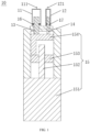
FIG. 1 is a schematic diagram of a liquid dispensing pump according to an embodiment of the present disclosure; -
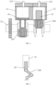
FIG. 2 is a schematic diagram of a liquid dispensing pump according to another embodiment of the present disclosure; -
FIG. 3 is a schematic diagram of a combination of the first crank, the first plunger, and the first liquid storage cylinder in the liquid dispensing pump as shown inFIG. 2 ; and -
FIG. 4 is a schematic diagram of a liquid dispensing device according to an embodiment of the present disclosure. - The meanings of reference numerals in the drawings are:
- 100-liquid dispensing device;
- 10- liquid dispensing pump, 11-first liquid storage cylinder, 111-first liquid inlet/outlet port, 12-second liquid storage cylinder, 121-second liquid inlet/outlet port, 13-first plunger, 14-second plunger, 15-driving assembly, 151-motor, 152-screw rod, 153-nut, 154-connection block, 155-first crank, 156-second crank, 16-first sealing ring, 17-second sealing ring;
- 20-first raw material tank;
- 30-second raw material tank;
- 40-mixing tank;
- 50-first liquid path switcher;
- 60-second liquid path switcher;
- 70-first water quality sensor;
- 80-second water quality sensor;
- 90-liquid supplement component, 91-liquid pump, 92-control valve, 93-filter, 94-manual valve.
- In order to facilitate the understanding of the present disclosure, the present disclosure will be described more fully below with reference to the relevant drawings. The preferred embodiments of the present disclosure are shown in the drawings. However, the present disclosure can be implemented in many different forms and is not limited to the embodiments described herein. On the contrary, the purpose of providing these embodiments is to make the understanding of the present disclosure more thorough and comprehensive.
- It should be noted that when an element is referred to as being "fixed to" another element, the element can be directly on the another element or there may be a mediate element. When an element is referred to as being "connected to" another element, the element can be directly connected to the another element or there may be a mediate element.
- All technical and scientific terms used herein have the same meaning as commonly understood by those skilled in the technical field of the present disclosure unless otherwise defined. The terms used in the specification of the present disclosure herein are only for the purpose of describing specific embodiments, and are not intended to limit the present disclosure.
- As shown in
FIGS. 1 to 3 , aliquid dispensing pump 10 according to an embodiment of the present disclosure is provided. - As shown in
FIG. 1 , theliquid dispensing pump 10 includes a firstliquid storage cylinder 11, a secondliquid storage cylinder 12, afirst plunger 13 movably connected to the firstliquid storage cylinder 11, asecond plunger 14 movably connected to the secondliquid storage cylinder 12, and a drivingassembly 15 connected to thefirst plunger 13 and thesecond plunger 14. The firstliquid storage cylinder 11 is provided with a first liquid inlet/outlet port 111. The secondliquid storage cylinder 12 is provided with a second liquid inlet/outlet port 121. One end of thefirst plunger 13 is inserted into an inner cavity of the firstliquid storage cylinder 11. One end of thesecond plunger 14 is inserted into an inner cavity of the secondliquid storage cylinder 12. The drivingassembly 15 is configured to drive thefirst plunger 13 and thesecond plunger 14 to reciprocate linearly. - In a case where the
liquid dispensing pump 10 is applied to the above-mentioned mixing of pure water and concentrated solution, because a proportion of pure water is greater than that of concentrated solution during the mixing and dilution, the firstliquid storage cylinder 11 may have a volume greater than that of the secondliquid storage cylinder 12, as shown inFIG. 1 . Thefirst plunger 13 has a cross-sectional area larger than that of thesecond plunger 14. The firstliquid storage cylinder 11 is configured to store raw materials with a relatively larger mixing proportion, and the secondliquid storage cylinder 12 is configured to store raw materials with a relatively less mixing proportion. Accordingly, the cross-sectional area of thefirst plunger 13 is greater than that of thesecond plunger 14, and the volume of the liquid pushed out by thefirst plunger 13 is greater than that of the liquid pushed out by thesecond plunger 14 under the premise of the same stroke. In the same way, theliquid dispensing pump 10 can also be configured to mix other different liquid raw materials. - In addition, in consideration of the movable connection between the
first plunger 13 and the firstliquid storage cylinder 11 and between thesecond plunger 14 and the secondliquid storage cylinder 12, in order to improve the sealing performance, in the present embodiment, afirst sealing ring 16 is provided at the junction between the firstliquid storage cylinder 11 and thefirst plunger 13, and asecond sealing ring 17 is provided at the junction between the secondliquid storage cylinder 12 and thesecond plunger 14. Thefirst sealing ring 16 and thesecond sealing ring 17 are configured to improve the sealing performance of the firstliquid storage cylinder 11 and the secondliquid storage cylinder 12, respectively. - The driving
assembly 15 can be implemented in various ways in order to achieve the linear reciprocating movement of thefirst plunger 13 and thesecond plunger 14. - For example, as shown in
FIG. 1 , in the present embodiment, the drivingassembly 15 includes amotor 151, ascrew rod 152 connected to themotor 151, anut 153 sleeved on thescrew rod 152, and aconnection block 154 connected to thenut 153. Theconnection block 154 is connected to thefirst plunger 13 and thesecond plunger 14, respectively. The linear reciprocating movement of thefirst plunger 13 and thesecond plunger 14 is realized by transmission of thescrew rod 152. - Taking the dilution of the concentrated solution as an example, as shown in
FIG. 1 , the firstliquid storage cylinder 11 and the secondliquid storage cylinder 12 are two mutually independent cavities with the volume of the firstliquid storage cylinder 11 greater than that of the secondliquid storage cylinder 12, and are configured to suck and discharge pure water and concentrated wash solution, respectively. Under the condition that the movement strokes of thefirst plunger 13 and thesecond plunger 14 are the same, the ratio of the cross-sectional areas of thefirst plunger 13 and thesecond plunger 14 is equivalent to the dilution ratio. Thefirst plunger 13 and thesecond plunger 14 are mounted on theconnection block 154, and theconnection block 154 is fixedly connected to thenut 153. Thenut 153 is engaged with thescrew rod 152, and thescrew rod 152 is fixedly connected to a rotating shaft of themotor 151. When themotor 151 rotates, thenut 153 rotates along with thescrew rod 152 and drives the movement of theconnection block 154, so that thefirst plunger 13 and thesecond plunger 14 move up and down in a piston manner. When themotor 151 rotates to drive thefirst plunger 13 and thesecond plunger 14 to move downward, pure water enters the firstliquid storage cylinder 11 from the first liquid inlet/outlet port 111, and the concentrated wash solution enters the secondliquid storage cylinder 12 from the second liquid inlet/outlet port 121. when themotor 151 rotates to drive thefirst plunger 13 and thesecond plunger 14 to move upward, the pure water in the firstliquid storage cylinder 11 is discharged through the first liquid inlet/outlet port 111, and the concentrated wash solution in the secondliquid storage cylinder 12 is discharged through the second liquid inlet/outlet port 121. - For another example, as shown in
FIGS. 2 and 3 , in other embodiments, the drivingassembly 15 includes amotor 151, a first crank 155 connected to themotor 151, and a second crank 156 connected to themotor 151. Thefirst crank 155 is connected to thefirst plunger 13. Thesecond crank 156 is connected to thesecond plunger 14. The linear reciprocating movement of thefirst plunger 13 and thesecond plunger 14 is realized by transmission of the cranks. - Further, the operating strokes of the
first plunger 13 and thesecond plunger 14 can be adjusted by adjusting the lengths of the first crank 155 and the second crank 156, so that the mixing ratio of the raw materials can be adjusted. In addition, they may also be in different phases, so that when one plunger moves downward, the other plunger moves upward, that is to say, when one plunger sucks liquid, the other plunger discharges liquid. This way can possess a higher proportioning efficiency. - It should be noted that, based on the design concept of the present disclosure, a plurality of plungers and corresponding liquid storage cylinders can be provided according to the type and mixing ratio of the raw materials. It is not limited to the case of the double plunger set forth in the present embodiment.
- In the above-mentioned
liquid dispensing pump 10, the drivingassembly 15 is configured to drive thefirst plunger 13 and thesecond plunger 14 to realize linear reciprocating movement, so that thefirst plunger 13 along with the firstliquid storage cylinder 11 and thesecond plunger 14 along with the secondliquid storage cylinder 12 each constitute a pump body that can suck and discharge liquid. During operation, the drivingassembly 15 drives thefirst plunger 13 and thesecond plunger 14 to operate simultaneously, that is, thefirst plunger 13 and thesecond plunger 14 move the same stroke each time. The ratio of the cross-sectional area of thefirst plunger 13 to thesecond plunger 14 is set according to a preset mixing ratio. In each cycle of the linear reciprocating movement of thefirst plunger 13 and thesecond plunger 14, the firstliquid storage cylinder 11 and the secondliquid storage cylinder 12 discharge the corresponding raw materials according to the preset mixing ratio. The raw materials flow together and are mixed in the subsequent liquid path to obtain a mixed liquid in the preset mixing ratio, thereby realizing the precise mixing of the different raw materials. Also, thisliquid dispensing pump 10 discharges the raw materials in the same ratio each time, so that uniform mixing can be achieved without using a specialized mixer. - On the basis of
FIG. 1 to FIG. 3 and with reference toFIG. 4 , aliquid dispensing pump 10 according to an embodiment of the present disclosure is provided. - As shown in
FIG. 4 , theliquid dispensing device 100 includes theliquid dispensing pump 10 as described above, and further includes a firstraw material tank 20, a secondraw material tank 30, a mixingtank 40, a firstliquid path switcher 50, and a secondliquid path switcher 60. The firstraw material tank 20 and the secondraw material tank 30 are configured to store raw materials, and themixing tank 40 is configured to store a mixed liquid of different raw materials. The firstliquid path switcher 50 is connected among the firstraw material tank 20, theliquid dispensing pump 10, and themixing tank 40. The secondliquid path switcher 60 is connected among the secondraw material tank 30, theliquid dispensing pump 10, and themixing tank 40. The firstliquid path switcher 50 and the secondliquid path switcher 60 are configured to realize the suction and discharge of the corresponding raw materials in cooperation with the suction and discharge operation of theliquid dispensing pump 10. - In the present embodiment, the first
liquid path switcher 50 and the secondliquid path switcher 60 are solenoid valves. In other embodiments, the firstliquid path switcher 50 and the secondliquid path switcher 60 are both plunger valves. Under the premise that switching between different liquid paths is enabled, the firstliquid path switcher 50 and the secondliquid path switcher 60 may also be other types of liquid path switching devices. - In addition, the number of liquid paths of the first
liquid path switcher 50 and the secondliquid path switcher 60 is adjusted according to the number of raw material tanks and the number of the mixingtanks 40. For example, in the present embodiment, the firstliquid path switcher 50 and the secondliquid path switcher 60 are both three-way solenoid valves. It can be understood that the firstliquid path switcher 50 and the secondliquid path switcher 60 may also be formed by a combination of two two-way solenoid valves. - In order to realize an automated liquid dispensing operation, in this embodiment, the first
raw material tank 20 is provided with a first liquid level sensor. The secondraw material tank 30 is provided with a second liquid level sensor. The mixingtank 40 is provided with a third liquid level sensor. The first liquid level sensor, the second liquid level sensor, and the third liquid level sensor are electrically connected to the drivingassembly 15, respectively. The first liquid level sensor is configured to detect whether the liquid level of the firstraw material tank 20 reaches a preset material-taking liquid level, and the second liquid level sensor is configured to detect whether the liquid level of the secondraw material tank 30 reaches a preset material-taking liquid level. The third liquid level sensor is configured to detect the liquid level height of the existing mixed liquid in themixing tank 40. According to the first liquid level sensor, the second liquid level sensor, and the third liquid level sensor, trigger signals for controlling the firstliquid path switcher 50, the secondliquid path switcher 60, and theliquid dispensing pump 10 to operate can be generated, thereby achieving the automated operation of liquid dispensing. - Taking the above-mentioned dilution of the concentrated wash solution as an example, as shown in
FIG. 4 , the automatic dilution and dispensing will start once the low-liquid level signal of the mixingtank 40 storing the diluted wash solution is detected, under the condition that the pure water in the firstraw material tank 20 and the concentrated wash solution in the secondraw material tank 30 are sufficient. For a single cycle, themotor 151 drives thefirst plunger 13 and thesecond plunger 14 to move downward, respectively sucking the pure water and concentrated solution in one cycle. After the liquid suction is completed, the firstliquid path switcher 50 and the secondliquid path switcher 60 are turned on, and the liquid path connected to theliquid dispensing pump 10 is switched to themixing tank 40 storing the diluted wash solution, so that the object connected by theliquid dispensing pump 10 is switched from the firstraw material tank 20 and the secondraw material tank 30 to themixing tank 40. Themotor 151 then drives thefirst plunger 13 and thesecond plunger 14 to move upward, so that the sucked pure water and the concentrated wash solution are discharged to themixing tank 40. Reciprocating cycles continue until a preset high liquid level is reached in themixing tank 40, and then the liquid dispensing operation is automatically stopped. - As shown in
FIG. 4 , in the present embodiment, a firstwater quality sensor 80 may be provided between the firstraw material tank 20 and the firstliquid path switcher 50. - Similarly, in the present embodiment, the mixing
tank 40 is provided with a drain port, and the drain port is connected to a second water quality sensor. - In addition, the
liquid dispensing device 100 can also be provided with aliquid supplement component 90. For example, in the present embodiment, as shown inFIG. 4 , aliquid supplement component 90 is provided for the firstraw material tank 20. For example, for the dilution of the concentrated wash solution, an automatic supplement of pure water can be set. Theliquid supplement component 90 is started once the liquid level detected by the first liquid level sensor is lower than a preset low liquid level. For example, theliquid supplement component 90 includes aliquid pump 91, acontrol valve 92, afilter 93, and amanual valve 94 connected in sequence. Theliquid pump 91 is started to pump pure water into the firstraw material tank 20 once the liquid level detected by the first liquid level sensor is lower than the preset low liquid level. Theliquid pump 91 is turned off once the liquid level detected by the first liquid level sensor is lower than the preset high liquid level. - In the
liquid dispensing device 100 as described above, the first liquid path switcher 50 selectively enables conduction of the liquid path between the firstraw material tank 20 and theliquid dispensing pump 10, and the second liquid path switcher 60 selectively enables conduction of the liquid path between the secondraw material tank 30 and theliquid dispensing pump 10. Theliquid dispensing pump 10 sucks raw materials from the firstraw material tank 20 and the secondraw material tank 30, respectively. Then, the first liquid path switcher 50 selectively enables conduction of the liquid path between the mixingtank 40 and theliquid dispensing pump 10, and the second liquid path switcher 60 selectively enables conduction of the liquid path between the mixingtank 40 and theliquid dispensing pump 10. Theliquid dispensing pump 10 discharges different raw materials into the mixingtank 40 according to a preset mixing ratio. In one suction and discharge cycle of theliquid dispensing pump 10, theliquid dispensing device 100 completes a period of liquid mixing in the mixing ratio that is accurate and uniform. - The above examples only express the preferred embodiments of the present disclosure with the relatively specific and detailed description, but should not be understood as a limitation on the scope of the present disclosure.
Claims (5)
- A liquid dispensing device (100) comprising,
a liquid dispensing pump (10) comprising:a first liquid storage cylinder (11) provided with a first liquid inlet/outlet port (111);a second liquid storage cylinder (12) provided with a second liquid inlet/outlet port (121);a first plunger (13) movably connected to the first liquid storage cylinder (11), one end of the first plunger (13) being inserted into an inner cavity of the first liquid storage cylinder (11);a second plunger (14) movably connected to the second liquid storage cylinder (12), one end of the second plunger (14) being inserted into an inner cavity of the second liquid storage cylinder (12); anda driving assembly (51) connected to the first plunger (13) and the second plunger (14);wherein the first plunger (13) has a cross-sectional area larger than that of the second plunger (14); andwherein the liquid dispensing device (100) further comprises:a first raw material tank (20);a second raw material tank (30);a mixing tank (40);a first liquid path switcher (50) connected among the first raw material tank (20), the liquid dispensing pump (10), and the mixing tank (40); anda second liquid path switcher (60) connected among the second raw material tank (30), the liquid dispensing pump (10), and the mixing tank (40);wherein, when the driving assembly (15) drives the first plunger (13) and the second plunger (14) to move in a first direction, the first liquid path switcher (50) is configured to selectively enable conduction of the liquid path between the first raw material tank (20) and the liquid dispensing pump (10) and the second liquid path switcher (30) is configured to selectively enable conduction of the liquid path between the second raw material tank (30) and the liquid dispensing pump (10), so that the liquid dispensing pump (10) sucks raw materials from the first raw material tank (20) and the second raw material tank (30); andwherein, when the driving assembly (15) drives the first plunger (13) and the second plunger (14) to move in a second direction opposite to the first direction, the first liquid path switcher (50) is configured to selectively enable conduction of the liquid path between the mixing tank (40) and the liquid dispensing pump (10) and the second liquid path switcher (60) is configured to selectively enable conduction of the liquid path between the mixing tank (40) and the liquid dispensing pump (10), so that the liquid dispensing pump (10) discharges different raw materials into the mixing tank (40). - The liquid dispensing device (100) according to claim 1, wherein the first raw material tank is provided with a first liquid level sensor; the second raw material tank (30) is provided with a second liquid level sensor; the mixing tank (40) is provided with a third liquid level sensor; the first liquid level sensor, the second liquid level sensor, and the third liquid level sensor being electrically connected to the driving assembly (15), respectively.
- The liquid dispensing device (100) according to claim 1, wherein the first liquid path switcher (50) and the second liquid path switcher (60) are solenoid valves or plunger valves.
- The liquid dispensing device (100) according to claim 1, wherein a first water quality sensor (70) is provided between the first raw material tank (20) and the first liquid path switcher (50).
- The liquid dispensing device (100) according to claim 1, wherein the mixing tank (40) is provided with a drain port, and the drain port is connected to a second water quality sensor (80).
Applications Claiming Priority (2)
| Application Number | Priority Date | Filing Date | Title |
|---|---|---|---|
| CN201910505523.4A CN110090570A (en) | 2019-06-12 | 2019-06-12 | With liquid pump and liquid dispensing device |
| PCT/CN2019/128051 WO2020248573A1 (en) | 2019-06-12 | 2019-12-24 | Liquid dispensing pump, and liquid dispensing device |
Publications (3)
| Publication Number | Publication Date |
|---|---|
| EP3950107A1 EP3950107A1 (en) | 2022-02-09 |
| EP3950107A4 EP3950107A4 (en) | 2023-01-11 |
| EP3950107B1 true EP3950107B1 (en) | 2024-07-31 |
Family
ID=67450840
Family Applications (1)
| Application Number | Title | Priority Date | Filing Date |
|---|---|---|---|
| EP19932461.7A Active EP3950107B1 (en) | 2019-06-12 | 2019-12-24 | Liquid dispensing pump, and liquid dispensing device |
Country Status (5)
| Country | Link |
|---|---|
| US (1) | US12440816B2 (en) |
| EP (1) | EP3950107B1 (en) |
| CN (1) | CN110090570A (en) |
| PL (1) | PL3950107T3 (en) |
| WO (1) | WO2020248573A1 (en) |
Families Citing this family (2)
| Publication number | Priority date | Publication date | Assignee | Title |
|---|---|---|---|---|
| CN110090570A (en) | 2019-06-12 | 2019-08-06 | 深圳市亚辉龙生物科技股份有限公司 | With liquid pump and liquid dispensing device |
| CN111318233B (en) * | 2020-03-15 | 2022-06-07 | 青岛海力加化学新材料有限公司 | A safe feeding device for hazardous articles production |
Family Cites Families (28)
| Publication number | Priority date | Publication date | Assignee | Title |
|---|---|---|---|---|
| DE2447358B2 (en) * | 1974-10-04 | 1979-03-22 | Kernforschungsanlage Juelich Gmbh, 5170 Juelich | Device for the preparation of a series of solutions with different concentrations |
| DE2846623A1 (en) * | 1978-10-26 | 1980-05-08 | Basf Ag | METHOD FOR THE PRODUCTION OF LAYER MAGNETOGRAM CARRIERS |
| US4366918A (en) * | 1979-04-20 | 1983-01-04 | Naka Seiki Company Limited | Variable ratio metering, mixing and dispensing apparatus |
| FR2536471B1 (en) | 1982-11-19 | 1987-06-12 | Binoche Michel | PUMP FOR DELIVERING MULTIPLE DIFFERENT PRODUCTS IN WELL-DEFINED PROPORTIONS |
| US4815042A (en) * | 1986-02-26 | 1989-03-21 | Micro Chemical, Inc. | Programmable apparatus and method for delivering microingredient feed additives to animals by weight |
| DE3624976A1 (en) | 1986-07-24 | 1988-02-04 | Sinsch Joachim | Device for metering and transporting liquid and pasty media |
| JP2824575B2 (en) | 1987-08-11 | 1998-11-11 | 株式会社日立製作所 | Low pulsating flow pump |
| US4927567A (en) * | 1989-06-23 | 1990-05-22 | The Coca-Cola Company | Motorless continuous carbonator |
| FR2726332B1 (en) | 1994-10-26 | 1997-01-24 | Francois Couillard | PISTON PUMPING SYSTEM DELIVERING FLUIDS WITH SUBSTANTIALLY CONSTANT FLOW RATE |
| DE19511758A1 (en) | 1995-03-30 | 1996-10-02 | Klaus Obermann Gmbh | Dosing and injection pump arrangement |
| JP3172429B2 (en) | 1996-03-29 | 2001-06-04 | 株式会社日立製作所 | Liquid chromatograph |
| DE20216295U1 (en) | 2002-10-23 | 2003-01-16 | Lüttmann, Erich, 26160 Bad Zwischenahn | Piston pump for multiple component adhesives has common drive shaft connected to lever arms coupled to connecting rods of different size pumping cylinders |
| CN2626602Y (en) * | 2003-06-28 | 2004-07-21 | 朱玉祥 | Automatic solution proportioning apparatus |
| JP4040049B2 (en) | 2005-03-18 | 2008-01-30 | 横浜ゴム株式会社 | Shot pump and variable speed two-component metering and mixing device |
| WO2007101786A1 (en) * | 2006-03-06 | 2007-09-13 | Novo Nordisk A/S | A drug delivery device with a valve |
| CN102297108B (en) | 2011-08-03 | 2013-08-14 | 杭州电子科技大学 | Hydraulic drive double-link piston pump for precisely fluid proportional mixing |
| AT513651B1 (en) * | 2012-11-21 | 2015-06-15 | Waizenauer Dietmar Bsc | Mixing plant for viscous media |
| CN103410696A (en) | 2013-06-27 | 2013-11-27 | 山东星源矿山设备集团有限公司 | Pneumatic two-fluid grouting pump |
| CN103994044A (en) | 2014-05-14 | 2014-08-20 | 苏州农业职业技术学院 | Crank connecting rod transmission type hydraulic pump with linear motor |
| CN103994045A (en) | 2014-05-14 | 2014-08-20 | 苏州农业职业技术学院 | Plunger piston type hydraulic pump with linear motors |
| US11178914B2 (en) * | 2014-05-23 | 2021-11-23 | Revolutionary Electronic Design, LLC | Vaping liquid dispensing and vending |
| CN104324628A (en) * | 2014-09-28 | 2015-02-04 | 武汉长江科创科技发展有限公司 | Static-state mixing apparatus used in preparation process of bi-component polyurea |
| CN204134593U (en) | 2014-10-17 | 2015-02-04 | 苏州大学 | The determining of a kind of liquid material batch mixer compares device |
| CN204233988U (en) | 2014-11-24 | 2015-04-01 | 杭州凡腾科技有限公司 | A kind of two phase flow ratio on-line mixing device |
| CN207887129U (en) * | 2017-12-27 | 2018-09-21 | 江苏海航新材料科技有限公司 | A kind of fire resistant infilling mixing arrangement |
| CN208526542U (en) * | 2018-05-16 | 2019-02-22 | 沈阳美狮化工有限公司 | A kind of raw material feeder for paint production |
| CN110090570A (en) | 2019-06-12 | 2019-08-06 | 深圳市亚辉龙生物科技股份有限公司 | With liquid pump and liquid dispensing device |
| CN210186898U (en) * | 2019-06-12 | 2020-03-27 | 深圳市亚辉龙生物科技股份有限公司 | Liquid dispensing pump and liquid dispensing device |
-
2019
- 2019-06-12 CN CN201910505523.4A patent/CN110090570A/en active Pending
- 2019-12-24 US US17/601,587 patent/US12440816B2/en active Active
- 2019-12-24 EP EP19932461.7A patent/EP3950107B1/en active Active
- 2019-12-24 PL PL19932461.7T patent/PL3950107T3/en unknown
- 2019-12-24 WO PCT/CN2019/128051 patent/WO2020248573A1/en not_active Ceased
Also Published As
| Publication number | Publication date |
|---|---|
| PL3950107T3 (en) | 2025-01-13 |
| WO2020248573A1 (en) | 2020-12-17 |
| US20220347640A1 (en) | 2022-11-03 |
| EP3950107A1 (en) | 2022-02-09 |
| CN110090570A (en) | 2019-08-06 |
| EP3950107A4 (en) | 2023-01-11 |
| US12440816B2 (en) | 2025-10-14 |
| WO2020248573A9 (en) | 2021-09-23 |
Similar Documents
| Publication | Publication Date | Title |
|---|---|---|
| US5328459A (en) | Apparatus and method for dispensing and aspirating high viscosity materials | |
| US5127547A (en) | Metering and dispensing apparatus | |
| US4244919A (en) | Sample diluting apparatus | |
| RU2692169C2 (en) | Pump capable of dosing both large volume and small volume of dye | |
| US20070164046A1 (en) | Beverage dispenser | |
| CN201291172Y (en) | Double-component fluid pressurization injection device | |
| CN102253150A (en) | Automatic sampler for liquid chromatograph | |
| KR101871701B1 (en) | Rotary-wave sub-assembly for pumping a fluid and rotary-wave pumping device | |
| JP5677649B1 (en) | Switching valve for flow analyzer | |
| US3572130A (en) | Liquid sample pick-up and dispensing apparatus | |
| US12440816B2 (en) | Liquid dispensing pump and liquid dispensing device | |
| JP2015092166A5 (en) | ||
| CN210186898U (en) | Liquid dispensing pump and liquid dispensing device | |
| JP2011007666A (en) | Sample liquid dilution method and device of the same | |
| GB1322600A (en) | Apparatus for feeding viscous materials | |
| US6503389B2 (en) | Liquid chromatograph | |
| US3131707A (en) | Proportioning medicator for waterers | |
| JP2020112060A (en) | Liquid pump priming method | |
| CN105128268B (en) | The continuous Coinjection molding apparatus of high pressure multi-cylinder | |
| JP2001082318A (en) | Reciprocating pump device | |
| CN208502995U (en) | Plunger pump and conveying system comprising same | |
| CN118976428A (en) | Preparation device, fluid preparation method and control device | |
| RU2299431C1 (en) | Method and system for providing continuous impulse-free stream of liquid | |
| CN220705851U (en) | High-efficiency numerical control liquid injection pump capable of bidirectionally discharging liquid | |
| CN223800846U (en) | A dual-injection pump switching coating device and coating machine |
Legal Events
| Date | Code | Title | Description |
|---|---|---|---|
| STAA | Information on the status of an ep patent application or granted ep patent |
Free format text: STATUS: THE INTERNATIONAL PUBLICATION HAS BEEN MADE |
|
| PUAI | Public reference made under article 153(3) epc to a published international application that has entered the european phase |
Free format text: ORIGINAL CODE: 0009012 |
|
| STAA | Information on the status of an ep patent application or granted ep patent |
Free format text: STATUS: REQUEST FOR EXAMINATION WAS MADE |
|
| 17P | Request for examination filed |
Effective date: 20211018 |
|
| AK | Designated contracting states |
Kind code of ref document: A1 Designated state(s): AL AT BE BG CH CY CZ DE DK EE ES FI FR GB GR HR HU IE IS IT LI LT LU LV MC MK MT NL NO PL PT RO RS SE SI SK SM TR |
|
| DAV | Request for validation of the european patent (deleted) | ||
| DAX | Request for extension of the european patent (deleted) | ||
| REG | Reference to a national code |
Ref country code: DE Ref legal event code: R079 Free format text: PREVIOUS MAIN CLASS: B01F0003080000 Ipc: F04B0013020000 Ref document number: 602019056382 Country of ref document: DE |
|
| A4 | Supplementary search report drawn up and despatched |
Effective date: 20221213 |
|
| RIC1 | Information provided on ipc code assigned before grant |
Ipc: F04B 9/111 20060101ALI20221207BHEP Ipc: F04B 9/109 20060101ALI20221207BHEP Ipc: F04B 1/22 20060101ALI20221207BHEP Ipc: F04B 13/02 20060101AFI20221207BHEP |
|
| P01 | Opt-out of the competence of the unified patent court (upc) registered |
Effective date: 20230530 |
|
| GRAP | Despatch of communication of intention to grant a patent |
Free format text: ORIGINAL CODE: EPIDOSNIGR1 |
|
| STAA | Information on the status of an ep patent application or granted ep patent |
Free format text: STATUS: GRANT OF PATENT IS INTENDED |
|
| RIC1 | Information provided on ipc code assigned before grant |
Ipc: F04B 9/111 20060101ALI20240206BHEP Ipc: F04B 9/109 20060101ALI20240206BHEP Ipc: F04B 1/22 20060101ALI20240206BHEP Ipc: F04B 13/02 20060101AFI20240206BHEP |
|
| INTG | Intention to grant announced |
Effective date: 20240307 |
|
| GRAS | Grant fee paid |
Free format text: ORIGINAL CODE: EPIDOSNIGR3 |
|
| GRAA | (expected) grant |
Free format text: ORIGINAL CODE: 0009210 |
|
| STAA | Information on the status of an ep patent application or granted ep patent |
Free format text: STATUS: THE PATENT HAS BEEN GRANTED |
|
| AK | Designated contracting states |
Kind code of ref document: B1 Designated state(s): AL AT BE BG CH CY CZ DE DK EE ES FI FR GB GR HR HU IE IS IT LI LT LU LV MC MK MT NL NO PL PT RO RS SE SI SK SM TR |
|
| REG | Reference to a national code |
Ref country code: CH Ref legal event code: EP Ref country code: GB Ref legal event code: FG4D |
|
| REG | Reference to a national code |
Ref country code: DE Ref legal event code: R096 Ref document number: 602019056382 Country of ref document: DE |
|
| REG | Reference to a national code |
Ref country code: IE Ref legal event code: FG4D |
|
| REG | Reference to a national code |
Ref country code: LT Ref legal event code: MG9D |
|
| REG | Reference to a national code |
Ref country code: NL Ref legal event code: MP Effective date: 20240731 |
|
| PG25 | Lapsed in a contracting state [announced via postgrant information from national office to epo] |
Ref country code: PT Free format text: LAPSE BECAUSE OF FAILURE TO SUBMIT A TRANSLATION OF THE DESCRIPTION OR TO PAY THE FEE WITHIN THE PRESCRIBED TIME-LIMIT Effective date: 20241202 |
|
| REG | Reference to a national code |
Ref country code: AT Ref legal event code: MK05 Ref document number: 1708680 Country of ref document: AT Kind code of ref document: T Effective date: 20240731 |
|
| PG25 | Lapsed in a contracting state [announced via postgrant information from national office to epo] |
Ref country code: PT Free format text: LAPSE BECAUSE OF FAILURE TO SUBMIT A TRANSLATION OF THE DESCRIPTION OR TO PAY THE FEE WITHIN THE PRESCRIBED TIME-LIMIT Effective date: 20241202 |
|
| PG25 | Lapsed in a contracting state [announced via postgrant information from national office to epo] |
Ref country code: NO Free format text: LAPSE BECAUSE OF FAILURE TO SUBMIT A TRANSLATION OF THE DESCRIPTION OR TO PAY THE FEE WITHIN THE PRESCRIBED TIME-LIMIT Effective date: 20241031 |
|
| PG25 | Lapsed in a contracting state [announced via postgrant information from national office to epo] |
Ref country code: NL Free format text: LAPSE BECAUSE OF FAILURE TO SUBMIT A TRANSLATION OF THE DESCRIPTION OR TO PAY THE FEE WITHIN THE PRESCRIBED TIME-LIMIT Effective date: 20240731 Ref country code: FI Free format text: LAPSE BECAUSE OF FAILURE TO SUBMIT A TRANSLATION OF THE DESCRIPTION OR TO PAY THE FEE WITHIN THE PRESCRIBED TIME-LIMIT Effective date: 20240731 Ref country code: GR Free format text: LAPSE BECAUSE OF FAILURE TO SUBMIT A TRANSLATION OF THE DESCRIPTION OR TO PAY THE FEE WITHIN THE PRESCRIBED TIME-LIMIT Effective date: 20241101 |
|
| PG25 | Lapsed in a contracting state [announced via postgrant information from national office to epo] |
Ref country code: BG Free format text: LAPSE BECAUSE OF FAILURE TO SUBMIT A TRANSLATION OF THE DESCRIPTION OR TO PAY THE FEE WITHIN THE PRESCRIBED TIME-LIMIT Effective date: 20240731 |
|
| PG25 | Lapsed in a contracting state [announced via postgrant information from national office to epo] |
Ref country code: LV Free format text: LAPSE BECAUSE OF FAILURE TO SUBMIT A TRANSLATION OF THE DESCRIPTION OR TO PAY THE FEE WITHIN THE PRESCRIBED TIME-LIMIT Effective date: 20240731 |
|
| PG25 | Lapsed in a contracting state [announced via postgrant information from national office to epo] |
Ref country code: IS Free format text: LAPSE BECAUSE OF FAILURE TO SUBMIT A TRANSLATION OF THE DESCRIPTION OR TO PAY THE FEE WITHIN THE PRESCRIBED TIME-LIMIT Effective date: 20241130 Ref country code: AT Free format text: LAPSE BECAUSE OF FAILURE TO SUBMIT A TRANSLATION OF THE DESCRIPTION OR TO PAY THE FEE WITHIN THE PRESCRIBED TIME-LIMIT Effective date: 20240731 |
|
| PG25 | Lapsed in a contracting state [announced via postgrant information from national office to epo] |
Ref country code: HR Free format text: LAPSE BECAUSE OF FAILURE TO SUBMIT A TRANSLATION OF THE DESCRIPTION OR TO PAY THE FEE WITHIN THE PRESCRIBED TIME-LIMIT Effective date: 20240731 |
|
| PG25 | Lapsed in a contracting state [announced via postgrant information from national office to epo] |
Ref country code: RS Free format text: LAPSE BECAUSE OF FAILURE TO SUBMIT A TRANSLATION OF THE DESCRIPTION OR TO PAY THE FEE WITHIN THE PRESCRIBED TIME-LIMIT Effective date: 20241031 Ref country code: ES Free format text: LAPSE BECAUSE OF FAILURE TO SUBMIT A TRANSLATION OF THE DESCRIPTION OR TO PAY THE FEE WITHIN THE PRESCRIBED TIME-LIMIT Effective date: 20240731 |
|
| PG25 | Lapsed in a contracting state [announced via postgrant information from national office to epo] |
Ref country code: RS Free format text: LAPSE BECAUSE OF FAILURE TO SUBMIT A TRANSLATION OF THE DESCRIPTION OR TO PAY THE FEE WITHIN THE PRESCRIBED TIME-LIMIT Effective date: 20241031 Ref country code: NO Free format text: LAPSE BECAUSE OF FAILURE TO SUBMIT A TRANSLATION OF THE DESCRIPTION OR TO PAY THE FEE WITHIN THE PRESCRIBED TIME-LIMIT Effective date: 20241031 Ref country code: NL Free format text: LAPSE BECAUSE OF FAILURE TO SUBMIT A TRANSLATION OF THE DESCRIPTION OR TO PAY THE FEE WITHIN THE PRESCRIBED TIME-LIMIT Effective date: 20240731 Ref country code: LV Free format text: LAPSE BECAUSE OF FAILURE TO SUBMIT A TRANSLATION OF THE DESCRIPTION OR TO PAY THE FEE WITHIN THE PRESCRIBED TIME-LIMIT Effective date: 20240731 Ref country code: IS Free format text: LAPSE BECAUSE OF FAILURE TO SUBMIT A TRANSLATION OF THE DESCRIPTION OR TO PAY THE FEE WITHIN THE PRESCRIBED TIME-LIMIT Effective date: 20241130 Ref country code: HR Free format text: LAPSE BECAUSE OF FAILURE TO SUBMIT A TRANSLATION OF THE DESCRIPTION OR TO PAY THE FEE WITHIN THE PRESCRIBED TIME-LIMIT Effective date: 20240731 Ref country code: GR Free format text: LAPSE BECAUSE OF FAILURE TO SUBMIT A TRANSLATION OF THE DESCRIPTION OR TO PAY THE FEE WITHIN THE PRESCRIBED TIME-LIMIT Effective date: 20241101 Ref country code: FI Free format text: LAPSE BECAUSE OF FAILURE TO SUBMIT A TRANSLATION OF THE DESCRIPTION OR TO PAY THE FEE WITHIN THE PRESCRIBED TIME-LIMIT Effective date: 20240731 Ref country code: ES Free format text: LAPSE BECAUSE OF FAILURE TO SUBMIT A TRANSLATION OF THE DESCRIPTION OR TO PAY THE FEE WITHIN THE PRESCRIBED TIME-LIMIT Effective date: 20240731 Ref country code: BG Free format text: LAPSE BECAUSE OF FAILURE TO SUBMIT A TRANSLATION OF THE DESCRIPTION OR TO PAY THE FEE WITHIN THE PRESCRIBED TIME-LIMIT Effective date: 20240731 Ref country code: AT Free format text: LAPSE BECAUSE OF FAILURE TO SUBMIT A TRANSLATION OF THE DESCRIPTION OR TO PAY THE FEE WITHIN THE PRESCRIBED TIME-LIMIT Effective date: 20240731 |
|
| PG25 | Lapsed in a contracting state [announced via postgrant information from national office to epo] |
Ref country code: DK Free format text: LAPSE BECAUSE OF FAILURE TO SUBMIT A TRANSLATION OF THE DESCRIPTION OR TO PAY THE FEE WITHIN THE PRESCRIBED TIME-LIMIT Effective date: 20240731 Ref country code: SM Free format text: LAPSE BECAUSE OF FAILURE TO SUBMIT A TRANSLATION OF THE DESCRIPTION OR TO PAY THE FEE WITHIN THE PRESCRIBED TIME-LIMIT Effective date: 20240731 |
|
| PG25 | Lapsed in a contracting state [announced via postgrant information from national office to epo] |
Ref country code: EE Free format text: LAPSE BECAUSE OF FAILURE TO SUBMIT A TRANSLATION OF THE DESCRIPTION OR TO PAY THE FEE WITHIN THE PRESCRIBED TIME-LIMIT Effective date: 20240731 |
|
| PG25 | Lapsed in a contracting state [announced via postgrant information from national office to epo] |
Ref country code: IT Free format text: LAPSE BECAUSE OF FAILURE TO SUBMIT A TRANSLATION OF THE DESCRIPTION OR TO PAY THE FEE WITHIN THE PRESCRIBED TIME-LIMIT Effective date: 20240731 Ref country code: SK Free format text: LAPSE BECAUSE OF FAILURE TO SUBMIT A TRANSLATION OF THE DESCRIPTION OR TO PAY THE FEE WITHIN THE PRESCRIBED TIME-LIMIT Effective date: 20240731 |
|
| REG | Reference to a national code |
Ref country code: DE Ref legal event code: R097 Ref document number: 602019056382 Country of ref document: DE |
|
| PLBE | No opposition filed within time limit |
Free format text: ORIGINAL CODE: 0009261 |
|
| STAA | Information on the status of an ep patent application or granted ep patent |
Free format text: STATUS: NO OPPOSITION FILED WITHIN TIME LIMIT |
|
| REG | Reference to a national code |
Ref country code: DE Ref legal event code: R119 Ref document number: 602019056382 Country of ref document: DE |
|
| PG25 | Lapsed in a contracting state [announced via postgrant information from national office to epo] |
Ref country code: MC Free format text: LAPSE BECAUSE OF FAILURE TO SUBMIT A TRANSLATION OF THE DESCRIPTION OR TO PAY THE FEE WITHIN THE PRESCRIBED TIME-LIMIT Effective date: 20240731 |
|
| 26N | No opposition filed |
Effective date: 20250501 |
|
| REG | Reference to a national code |
Ref country code: CH Ref legal event code: PL |
|
| PG25 | Lapsed in a contracting state [announced via postgrant information from national office to epo] |
Ref country code: LU Free format text: LAPSE BECAUSE OF NON-PAYMENT OF DUE FEES Effective date: 20241224 |
|
| GBPC | Gb: european patent ceased through non-payment of renewal fee |
Effective date: 20241224 |
|
| PG25 | Lapsed in a contracting state [announced via postgrant information from national office to epo] |
Ref country code: SE Free format text: LAPSE BECAUSE OF FAILURE TO SUBMIT A TRANSLATION OF THE DESCRIPTION OR TO PAY THE FEE WITHIN THE PRESCRIBED TIME-LIMIT Effective date: 20240731 |
|
| REG | Reference to a national code |
Ref country code: BE Ref legal event code: MM Effective date: 20241231 |
|
| PG25 | Lapsed in a contracting state [announced via postgrant information from national office to epo] |
Ref country code: DE Free format text: LAPSE BECAUSE OF NON-PAYMENT OF DUE FEES Effective date: 20250701 |
|
| PG25 | Lapsed in a contracting state [announced via postgrant information from national office to epo] |
Ref country code: BE Free format text: LAPSE BECAUSE OF NON-PAYMENT OF DUE FEES Effective date: 20241231 Ref country code: GB Free format text: LAPSE BECAUSE OF NON-PAYMENT OF DUE FEES Effective date: 20241224 |
|
| PG25 | Lapsed in a contracting state [announced via postgrant information from national office to epo] |
Ref country code: FR Free format text: LAPSE BECAUSE OF NON-PAYMENT OF DUE FEES Effective date: 20241231 |
|
| PG25 | Lapsed in a contracting state [announced via postgrant information from national office to epo] |
Ref country code: CH Free format text: LAPSE BECAUSE OF NON-PAYMENT OF DUE FEES Effective date: 20241231 |
|
| PG25 | Lapsed in a contracting state [announced via postgrant information from national office to epo] |
Ref country code: IE Free format text: LAPSE BECAUSE OF NON-PAYMENT OF DUE FEES Effective date: 20241224 |
|
| PGFP | Annual fee paid to national office [announced via postgrant information from national office to epo] |
Ref country code: CZ Payment date: 20251219 Year of fee payment: 7 |
|
| PGFP | Annual fee paid to national office [announced via postgrant information from national office to epo] |
Ref country code: PL Payment date: 20251223 Year of fee payment: 7 |
|
| PGFP | Annual fee paid to national office [announced via postgrant information from national office to epo] |
Ref country code: RO Payment date: 20251223 Year of fee payment: 7 |
|
| PG25 | Lapsed in a contracting state [announced via postgrant information from national office to epo] |
Ref country code: CY Free format text: LAPSE BECAUSE OF FAILURE TO SUBMIT A TRANSLATION OF THE DESCRIPTION OR TO PAY THE FEE WITHIN THE PRESCRIBED TIME-LIMIT Effective date: 20240731 |