JP4040049B2 - Shot pump and variable speed two-component metering and mixing device - Google Patents
Shot pump and variable speed two-component metering and mixing device Download PDFInfo
- Publication number
- JP4040049B2 JP4040049B2 JP2005079511A JP2005079511A JP4040049B2 JP 4040049 B2 JP4040049 B2 JP 4040049B2 JP 2005079511 A JP2005079511 A JP 2005079511A JP 2005079511 A JP2005079511 A JP 2005079511A JP 4040049 B2 JP4040049 B2 JP 4040049B2
- Authority
- JP
- Japan
- Prior art keywords
- cylinder
- piston
- shot pump
- inlet
- outlet
- Prior art date
- Legal status (The legal status is an assumption and is not a legal conclusion. Google has not performed a legal analysis and makes no representation as to the accuracy of the status listed.)
- Active
Links
- 239000003795 chemical substances by application Substances 0.000 claims description 64
- 239000000463 material Substances 0.000 claims description 37
- 239000007788 liquid Substances 0.000 claims description 22
- 239000004848 polyfunctional curative Substances 0.000 claims description 10
- 239000000853 adhesive Substances 0.000 description 5
- 230000001070 adhesive effect Effects 0.000 description 5
- 238000001879 gelation Methods 0.000 description 4
- 238000012423 maintenance Methods 0.000 description 4
- 238000000034 method Methods 0.000 description 3
- 238000000926 separation method Methods 0.000 description 3
- 238000009825 accumulation Methods 0.000 description 2
- 238000010586 diagram Methods 0.000 description 2
- 238000006073 displacement reaction Methods 0.000 description 2
- 230000003028 elevating effect Effects 0.000 description 2
- 239000000203 mixture Substances 0.000 description 2
- 230000003068 static effect Effects 0.000 description 2
- 230000009191 jumping Effects 0.000 description 1
- 239000002075 main ingredient Substances 0.000 description 1
- 230000014759 maintenance of location Effects 0.000 description 1
- 239000003566 sealing material Substances 0.000 description 1
Images


Classifications
-
- F—MECHANICAL ENGINEERING; LIGHTING; HEATING; WEAPONS; BLASTING
- F04—POSITIVE - DISPLACEMENT MACHINES FOR LIQUIDS; PUMPS FOR LIQUIDS OR ELASTIC FLUIDS
- F04B—POSITIVE-DISPLACEMENT MACHINES FOR LIQUIDS; PUMPS
- F04B13/00—Pumps specially modified to deliver fixed or variable measured quantities
- F04B13/02—Pumps specially modified to deliver fixed or variable measured quantities of two or more fluids at the same time
-
- B—PERFORMING OPERATIONS; TRANSPORTING
- B01—PHYSICAL OR CHEMICAL PROCESSES OR APPARATUS IN GENERAL
- B01F—MIXING, e.g. DISSOLVING, EMULSIFYING OR DISPERSING
- B01F35/00—Accessories for mixers; Auxiliary operations or auxiliary devices; Parts or details of general application
- B01F35/80—Forming a predetermined ratio of the substances to be mixed
- B01F35/88—Forming a predetermined ratio of the substances to be mixed by feeding the materials batchwise
- B01F35/882—Forming a predetermined ratio of the substances to be mixed by feeding the materials batchwise using measuring chambers, e.g. volumetric pumps, for feeding the substances
- B01F35/8822—Forming a predetermined ratio of the substances to be mixed by feeding the materials batchwise using measuring chambers, e.g. volumetric pumps, for feeding the substances using measuring chambers of the piston or plunger type
-
- B—PERFORMING OPERATIONS; TRANSPORTING
- B01—PHYSICAL OR CHEMICAL PROCESSES OR APPARATUS IN GENERAL
- B01F—MIXING, e.g. DISSOLVING, EMULSIFYING OR DISPERSING
- B01F2101/00—Mixing characterised by the nature of the mixed materials or by the application field
- B01F2101/36—Mixing of ingredients for adhesives or glues; Mixing adhesives and gas
-
- F—MECHANICAL ENGINEERING; LIGHTING; HEATING; WEAPONS; BLASTING
- F04—POSITIVE - DISPLACEMENT MACHINES FOR LIQUIDS; PUMPS FOR LIQUIDS OR ELASTIC FLUIDS
- F04B—POSITIVE-DISPLACEMENT MACHINES FOR LIQUIDS; PUMPS
- F04B2205/00—Fluid parameters
- F04B2205/09—Flow through the pump
Description
この発明は、ペースト状の接着剤等を移送するショットポンプ及びそれを使用した可変速型二液計量混合装置に関し、更に詳しくは被移送物が内部に滞留してゲル化する等の不具合を回避できるショットポンプ及びそれを使用した可変速型二液計量混合装置に関する。 The present invention relates to a shot pump for transferring paste-like adhesive and the like, and a variable speed two-component metering / mixing device using the same, and more specifically, avoids problems such as the object to be transferred staying inside and gelling. The present invention relates to a shot pump that can be used and a variable-speed two-liquid metering and mixing apparatus using the same.
従来、建築構造物等で使用される主剤と硬化剤と等から成るシーリング材は、使用時に主剤と硬化剤とを二液混合装置を用いて所定の割合で混合させた後に使用している(例えば、特許文献1参照)。 Conventionally, a sealing material composed of a main agent and a curing agent and the like used in a building structure or the like is used after mixing the main agent and the curing agent at a predetermined ratio using a two-component mixing device at the time of use ( For example, see Patent Document 1).
そして、ペースト状態の接着剤をポンプで圧送するときには、ギアポンプ、トロコイダルポンプ、ショットポンプが使用されているが、ギアポンプ、トロコイダルポンプの場合には、圧力差による材料リークやポンプの磨耗により定量性が失われるという問題がある。 Gear pumps, trochoidal pumps, and shot pumps are used to pump paste adhesives with a pump. However, in the case of gear pumps and trochoidal pumps, the quantity is determined by material leaks due to pressure differences and pump wear. There is a problem of loss of sex.
そのため、二液計量混合装置では、一般には、主剤と硬化剤とを主剤用のショットポンプと硬化剤用のショットポンプとに各々充填し、一台の駆動モータにより同時に押し出して混合機により混合させた後、この混合剤を吐出させている。 For this reason, in a two-component metering and mixing apparatus, generally, the main agent and the curing agent are filled in a shot pump for the main agent and a shot pump for the curing agent, respectively, and are simultaneously extruded by a single drive motor and mixed by a mixer. After that, the mixture is discharged.
このショットポンプは、シリンダ内に設けたピストンがモーター駆動または油圧駆動で上昇する際に主剤や硬化剤等の被移送物をシリンダに吸い込み、ピストンの下降で出口から吐出する構成になっており、このピストンの移動量で吐出量が定まるため、このショットポンプの場合は、定量性については問題無い。 This shot pump is configured such that when the piston provided in the cylinder rises by motor drive or hydraulic drive, the material to be transferred such as the main agent and curing agent is sucked into the cylinder and discharged from the outlet when the piston is lowered. Since the discharge amount is determined by the movement amount of the piston, there is no problem with the quantitativeness in the case of this shot pump.
しかしながら、このショットポンプでは、被移送物が、ポンプ内に滞留してゲル化などの不具合が発生するという問題がある。つまり、従来のショットポンプでは、図7に示すように、出口と入口の両方がピストン先端側に対面するシリンダの底部側に設けられているため、従来のピストンが全部下降し終わらない状態から上昇して材料を吸い込むと、材料がピストン先端に面しているシリンダ上部の部分に、被移送物が殆ど移動しないデッドフロー部分が生じ、新しく吸引した被移送物と置換されなくなる。そのため、この部分に滞留した被移送物がゲル化してしまう。 However, in this shot pump, there is a problem that the transferred object stays in the pump and causes problems such as gelation. That is, in the conventional shot pump, as shown in FIG. 7, since both the outlet and the inlet are provided on the bottom side of the cylinder facing the piston tip side, the conventional piston is lifted from a state where the piston does not end down completely. When the material is sucked in, a dead flow portion in which the material to be transferred hardly moves is generated in the upper part of the cylinder facing the tip of the piston, and it is not replaced with the newly sucked material to be transferred. Therefore, the transferred object staying in this portion is gelled.
また、一方で、吐出装置全体としての液体の吐出を途切れることなく行うことができるように、シリンダ及び、このシリンダ内に配置した進退部材(プランジャ若しくはピストン)を備え、進退部材の進入変位に伴ってシリンダ内の液体を吐出し、その進退部材の後退変位に伴ってシリンダ内へ液体を吸入するポンプ本体を複数配設し、いずれかのポンプ本体の吐出作動に当って、他のいずれかのポンプ本体を吸入作動若しくは休止させる液体吐出装置が提案され、ポンプ本体では、プランジャの太径側のシリンダ端部側面に入口を、プランジャの小径側のシリンダ端部底面に出口を設けているものがある(例えば、特許文献2参照。)。 On the other hand, a cylinder and a forward / backward member (plunger or piston) arranged in the cylinder are provided so that the liquid discharge as the whole discharge device can be performed without interruption, and accompanying the forward displacement of the forward / backward member. A plurality of pump bodies that discharge the liquid in the cylinder and suck the liquid into the cylinder in accordance with the backward displacement of the advancing and retreating member. There has been proposed a liquid discharge device for inhaling or pausing the pump body. In the pump body, an inlet is provided on the cylinder end side of the plunger on the large diameter side, and an outlet is provided on the bottom surface of the cylinder end on the small diameter side of the plunger. (For example, refer to Patent Document 2).
この構成によれば、プランジャが上昇する時に上側の入口側から液体を吸引するので、プランジャとシリンダの間の間隙を液体が通り、しかもプランジャの進行方向と液体の流入方向が逆方向になる。そのため、吸引抵抗が大きくなるので、ペースト状態の接着剤等の粘性の強い被移送物には向かないという問題がある。また吸引抵抗を少なくするためにプランジャとシリンダの間の間隙を大きくすると、偏流が生じ、シリンダ内の被移送物が十分に置き換わらなくなるという問題を生じる。 According to this configuration, since the liquid is sucked from the upper inlet side when the plunger moves up, the liquid passes through the gap between the plunger and the cylinder, and the direction in which the plunger moves and the direction in which the liquid flows in are reversed. For this reason, the suction resistance increases, so that there is a problem that it is not suitable for a highly viscous transfer object such as an adhesive in a paste state. Further, if the gap between the plunger and the cylinder is increased in order to reduce the suction resistance, there arises a problem that a drift occurs and the transferred object in the cylinder cannot be sufficiently replaced.
また、液体に含まれている気体成分は上昇するが、プランジャが下降する時に下側の出口から液体が吐出されるため、この気体成分は排出され難く、シリンダ内にエア溜まりを発生させ易いという問題がある。
本発明は上記の問題点を解決すべくなされたものであり、その目的は、定量吐出性を確保しつつ、ポンプ内における被移送物の滞留とこの滞留に起因する被移送物のゲル化を防止でき、メンテナンス無しで長期間使用することができるショットポンプ及び可変速型二液計量混合装置を提供するこことにある。 The present invention has been made to solve the above-mentioned problems, and its purpose is to retain the material to be transported in the pump and to gel the material to be transported due to this retention while ensuring the quantitative discharge performance. An object of the present invention is to provide a shot pump and a variable speed two-component metering and mixing device that can be prevented and used for a long period of time without maintenance.
上記の目的を達成するため本発明のショットポンプは、上下方向に立設したシリンダに、被移送物のシリンダへの流入のみを可能にする逆止弁を有する入口と、被移送物のシリンダからの流出のみを可能にする逆止弁を有する出口とを設け、シリンダ内をピストンが上下に往復動してペースト状態の被移送物を入口から吸引して出口から吐出するショットポンプにおいて、ピストンの外径に対するピストン側面とシリンダの内側の側面との間隙の比を1/50〜2とし、前記入口をシリンダの下端面につなげてシリンダの側面下端部に設けるとともに、前記出口をシリンダの上端面につなげてシリンダの側面上端部に設けて、被移送物を前記入口から吸引して、前記ピストン側面とシリンダの内側の側面との間を通過させて前記出口から吐出するように構成する。 In order to achieve the above object, a shot pump according to the present invention includes an inlet having a check valve that allows only an inflow of a transferred object to a cylinder, and a cylinder of the transferred object. of an outlet with a check valve that only permits the outflow is provided, at the shot pump to the cylinder piston is discharged from the outlet by suction to be transported product from the inlet of the reciprocating to paste form up and down, the piston the gap ratio between the piston side surface and the cylinder of the inner side to the outer diameter and 1 / 50-2, Rutotomoni provided on the side lower portion of the cylinder by connecting the inlet to the lower end surface of the cylinder, the outlet on the cylinder provided on a side surface upper portion of the cylinder by connecting the end face, by sucking the object to be transported material from said inlet, discharge from the outlet by passing between the inner side surface of the piston side and cylinder It is configured so that.
また、本発明の可変速型二液計量混合装置は、主剤用のショットポンプと硬化剤用のショットポンプとに材料供給源から主剤と硬化剤とを充填し、駆動モータにより各ショットポンプを駆動させて所定の割合で主剤と硬化剤とを押出して混合機により混合させ、この混合剤を吐出させると共に、前記主剤用のショットポンプと前記硬化剤用のショットポンプとに、それぞれを駆動させる回転速度の制御可能な駆動モータを設置し、この駆動モータの回転速度を制御して主剤と硬化剤との混合比率を任意に設定する可変速型二液計量混合装置において、前記各ショットポンプに対する被移送物の充填完了圧を所定の一定圧に設定可能に構成すると共に、前記ショットポンプを、上下方向に立設したシリンダに、被移送物のシリンダへの流入のみを可能にする逆止弁を有する入口と、被移送物のシリンダからの流出のみを可能にする逆止弁を有する出口とを設け、ピストンの外径に対するピストン側面とシリンダの内側の側面との間隙の比を1/50〜2とし、前記入口をシリンダの下端面につなげてシリンダの側面下端部に設けるとともに、前記出口をシリンダの上端面につなげてシリンダの側面上端部に設けて、シリンダの下端側から上端側に向かってピストンが移動する時にペースト状態の被移送物を前記入口から吸引して、シリンダの上端側から下端側に向かってピストンが移動する時にペースト状態の被移送物を前記ピストン側面とシリンダの内側の側面との間を通過させて前記出口から吐出するように構成する。 Further, the variable speed two-component metering / mixing device of the present invention fills the main agent shot pump and the hardener shot pump with the main agent and the hardener from the material supply source, and drives each shot pump by a drive motor. The main agent and the curing agent are extruded at a predetermined ratio and mixed by a mixer. The mixture is discharged, and the main agent shot pump and the curing agent shot pump are driven to rotate. In a variable-speed two-component metering / mixing device in which a drive motor capable of controlling the speed is installed and the mixing ratio of the main agent and the curing agent is arbitrarily set by controlling the rotational speed of the drive motor, filling completion pressure of the transfer material while capable of setting a predetermined constant pressure, the shot pump, the cylinder provided upright in the vertical direction, only flows into the cylinders of the transfer material An inlet having a check valve which allows, provided an outlet having a check valve which allows only flow out from the cylinder of the transfer material, the gap between the piston side surface and the cylinder of the inner side to the outer diameter of the piston ratio was 1 / 50-2, provided the inlet Rutotomoni provided on the side lower portion of the cylinder by connecting the lower end surface of the cylinder, the side upper end of the cylinder by connecting the outlet to the upper end surface of the cylinder, the cylinder from the lower end to suck the object to be transported of paste state when the piston upward end is moved from said inlet, a paste state when the piston moves toward the lower end from the top end side of the cylinder The transfer object is configured to pass between the side surface of the piston and the inner side surface of the cylinder and to be discharged from the outlet.
本発明のショットポンプ及び可変速型二液計量混合装置によれば、被移送物の入口をシリンダの下端面につなげてシリンダの側面下端部に設けるとともに、出口をシリンダの上端面につなげてシリンダの側面上端部に設けたので、シリンダ内の材料が置換されながら吐出される。そのため、デッドフローが発生しない。 According to the shot pump and the variable speed two-liquid metering and mixing apparatus of the present invention, the cylinder is provided with the inlet of the transferred object connected to the lower end surface of the cylinder and provided at the lower end of the side surface of the cylinder, and the outlet connected to the upper end surface of the cylinder. Since it is provided at the upper end of the side surface , the material in the cylinder is discharged while being replaced. Therefore, no dead flow occurs.
従って、ショットポンプの特性である定量吐出性を確保しつつ、ショットポンプ内部における被移送物の滞留とこの滞留に起因する被移送物のゲル化等を防止でき、メンテナンス無しで長期間使用することができる。 Therefore, it is possible to prevent stagnation of the material to be transported inside the shot pump and gelation of the material to be transported due to this stagnation while ensuring the constant discharge property that is a characteristic of the shot pump, and use it for a long time without maintenance. Can do.
そして、ピストンが上昇する時に下側の入口側から被移送物を吸引するので、ピストンの進行方向と被移送物の流入方向が同方向になる。そのため、吸引抵抗が小さくなる。一方、ピストンとシリンダとの間の間隙を被移送物が通る吐出時には大きな圧力を発生できる加圧状態にあるので、間隙部分の被移送物の全量が置き換わるように間隙を狭くしても容易に吐出できる。そのため、ペースト状態の接着剤等の粘性の強い被移送物に十分に対応できる。 And since a to-be-transferred object is attracted | sucked from a lower inlet side when a piston raises, the advancing direction of a piston and the inflow direction of a to-be-transferred object become the same direction. Therefore, the suction resistance is reduced. On the other hand, since it is in a pressurized state that can generate a large pressure when the object to be transferred passes through the gap between the piston and the cylinder, it is easy even if the gap is narrowed so that the entire amount of the object to be transferred is replaced. Can be discharged. Therefore, it is possible to sufficiently cope with a highly viscous transfer object such as an adhesive in a paste state.
また、被移送物に含まれている気体成分は上昇して、シリンダの上部に到達し、出口から被移送物と共に排出されるので、シリンダ内にエア溜まりが発生しない。従って、正確な比率混合が可能となり、被移送物の硬化、分離を無くすことができ、品質の向上を図ることができる。 Further, the gas component contained in the transferred object rises, reaches the upper part of the cylinder, and is discharged together with the transferred object from the outlet, so that no air pool is generated in the cylinder. Accordingly, accurate ratio mixing is possible, and it is possible to eliminate the curing and separation of the transferred object, thereby improving the quality.
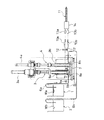
最初に、本発明のショットポンプの実施形態について、図1を参照しながら説明する。このショットポンプ100は、シリンダ101とピストン102とからなり、被移送物の入口103がシリンダ101のピストン先端側と対面する側(図1ではシリンダの下端側)に設けられ、また、出口104をシリンダ101のピストン根元側(図1ではシリンダの上端側)に設けられる。
First, an embodiment of the shot pump of the present invention will be described with reference to FIG. This
そして、このピストン102の外径に対するピストン側面102sとシリンダ101の内側の側面101sとの間隙δの比は1/50〜2にして形成される。また、入口103と出口104にはそれぞれ逆止弁103a,104a(図示しない)が設けられ、一方方向のみ被移送物が流入又は流出可能とする。
The ratio of the gap δ between the
この構成により、シリンダ101内に設けたピストン102が不図示のモータ駆動または油圧駆動で上昇する際に被移送物は入口103から吸引され、ピストン102の下降で間隙δを通過して出口104から吐出される。このピストン102の外径に対する間隙δの比が1/50以上あれば、ペースト状態の接着剤などはこの部分に流れ込み、つまり、シリンダ内に被移送物の滞留を防止することができる。また、2以下とすることにより、この間隙δの部分において定量吐出性を確保しつつ被移送物が確実に入れ換わるようにすることができる。特に、粘性の強い被移送物に用いる場合、加圧ポンプで被移送物に10MPa程度の加圧をすると、ピストンが押し上げられて、吸引が容易となり好ましい。
With this configuration, when the
従って、ショットポンプの特性である定量吐出性を確保しつつ、ショットポンプ内部における被移送物の滞留とこの滞留に起因する被移送物のゲル化等を防止でき、メンテナンス無しで長期間使用することができる
次に、本発明の実施の形態の可変速型二液計量混合装置について、図2〜図6を参照しながら説明する。
Therefore, it is possible to prevent stagnation of the material to be transported inside the shot pump and gelation of the material to be transported due to this stagnation while ensuring the constant discharge property that is a characteristic of the shot pump, and use it for a long time without maintenance. Next, the variable-speed two-component metering / mixing device according to the embodiment of the present invention will be described with reference to FIGS.
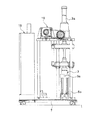
図2は、この発明の可変速型二液計量混合制御方法を実施するため装置全体の概略構成図を示す。主剤Waは、材料供給源(例えば、ペール缶等)1から圧力計5aを備えた配管6aを介して、昇降シリンダー3aで駆動される主剤用のショットポンプ3に供給されるように構成される。また、硬化剤Wbは材料供給源(例えば、ペール缶等)2から圧力計5bを備えた配管6bを介して、昇降シリンダー4aで駆動される硬化剤用のショットポンプ4に供給されるように構成される。
FIG. 2 is a schematic configuration diagram of the entire apparatus for carrying out the variable speed two-liquid metering and mixing control method of the present invention. The main agent Wa is configured to be supplied from a material supply source (for example, a pail can) 1 to the main
そして、本発明では、主剤用のショットポンプ3と硬化剤用のショットポンプ4は、それぞれ上記したショットポンプ100で形成される。これらのショットポンプ3、4は、移動可能な架台7上に設置され、この主剤用のショットポンプ3と硬化剤用のショットポンプ4との下部側に、上記のショットポンプ100の入口103に対応する主剤Waと硬化剤Wbとの充填供給口8a,8bを設け、この充填供給口8a,8bに前記配管6a,6bが接続をする。また、主剤用のショットポンプ3と硬化剤用のショットポンプ4との上部側には、上記のショットポンプ100の出口104に対応する主剤Waと硬化剤Wbとの吐出口9a,9bが設けてある。
In the present invention, the
また、主剤用のショットポンプ3と硬化剤用のショットポンプ4との吐出口9a,9bは、配管10a,10bを介してスタティックミキサー等の混合機11に接続され、配管10a,10bには、圧力センサー12及びエアーまたは電磁式のバルブ13a,13bを備えた混合部14を設け、この混合部14には、スタテックミキサー(またはダイナミックミキサー)等の混合機11が取付けられている。
The
前記主剤用のショットポンプ3と硬化剤用のショットポンプ4は、図3〜図6に示すように、各ショットポンプ3及び4を駆動させる駆動モータ16,17が設置され、この駆動モータ16,17は、制御装置18を介して回転速度を制御出来るように構成されている。即ち、制御装置18により、駆動モータ16,17の回転速度を制御し、前記主剤用のショットポンプ3と硬化剤用のショットポンプ4とに充填された主剤Waと硬化剤Wbとの混合比率を任意に設定し得るように構成されている。
As shown in FIGS. 3 to 6, the main agent shot
次に、上記の構成の可変速型二液計量混合装置における可変速型二液計量混合制御方法について説明する。 Next, a variable speed type two liquid metering and mixing method in the variable speed type two liquid metering and mixing apparatus having the above configuration will be described.
材料供給源1,2から供給された主剤Waと硬化剤Wbとを、主剤用のショットポンプ3と硬化剤用のショットポンプ4との充填供給口8a,8bから各々充填し、各々に設けた駆動モータ16,17の回転速度を制御装置18を介して制御しながら混合比率を任意に設定する。
The main agent Wa and the curing agent Wb supplied from the
そして、この設定した主剤Waと硬化剤Wbとを、各ショットポンプ3,4とバルブ13間に設けた圧力センサー12に充填完了圧力を設定して一定圧となるようにし、バルブ13a,13bを備えた混合部14を介して主剤Waと硬化剤Wbとの吐出量を一定として混合機11により混合させて吐出させる。
Then, the main agent Wa and the curing agent Wb thus set are set to a constant pressure by setting the filling completion pressure to the
このような制御方法により、主剤Waと硬化剤Wbとを混合制御することにより、主剤Waと硬化剤Wbとの混合比率を自由に設定することが出来、これにより混合比率の異なる材料でも混合することが可能であり、また混合比率の異なる装置を個々に持つことが無くコストを低減させることが出来、更に材料開発の時間短縮が可能であることから材料開発を容易に行うことが出来るものである。 By controlling the mixing of the main agent Wa and the curing agent Wb by such a control method, the mixing ratio of the main agent Wa and the curing agent Wb can be freely set, thereby mixing even materials having different mixing ratios. It is possible to reduce the cost without individually having devices with different mixing ratios, and the material development time can be shortened. is there.
また、各ショットポンプ3,4に対する材料の充填完了圧を一定圧に設定出来るので、飛び出し量の比率不良が無くなり、接着不良を防止することが出来、更に、デッドストックを無くすことが出来る事により、エアー溜まりが無くなり、正確な比率混合が可能となり、材料の硬化、分離を無くすことが出来、品質の向上を図ることが出来るものである。 In addition, since the material filling completion pressure for each shot pump 3 and 4 can be set to a constant pressure, there is no jumping ratio failure, adhesion failure can be prevented, and dead stock can be eliminated. In addition, air accumulation is eliminated, accurate ratio mixing is possible, and curing and separation of materials can be eliminated, and quality can be improved.
この構成の可変速型二液計量混合装置では、一台の可変速型二液計量混合装置にて、主剤と硬化剤との混合比率を自由に設定することが出来るため、混合比率の異なる材料でも混合することが可能であり、混合比率の異なる装置を個々に持つことが無くコストを低減させることが出来、更に材料開発の時間短縮が可能であることから材料開発を容易に行うことが出来る。 In the variable speed type two liquid metering and mixing device of this configuration, the mixing ratio of the main agent and the curing agent can be set freely with one variable speed two liquid metering and mixing device, so the materials with different mixing ratios However, it is possible to mix, and it is possible to reduce the cost without individually having devices with different mixing ratios, and further, the material development time can be shortened, so that the material development can be easily performed. .
また、各ショットポンプに対する材料の充填完了圧を一定圧に設定可能であるため、飛び出し量の比率不良が無くなり、接着不良を防止することが出来る。 In addition, since the filling completion pressure of the material for each shot pump can be set to a constant pressure, the ratio of the pop-out amount is eliminated and adhesion failure can be prevented.
その上、主剤用のショットポンプ3と硬化剤用のショットポンプ4において、図1の構成のショットポンプ100を使用しているので、定量吐出性を確保しつつ、ショットポンプ内部における被移送物の滞留とこの滞留に起因する被移送物のゲル化等を防止でき、メンテナンス無しで長期間使用することができる。
In addition, since the
そして、デッドストックを無くすことが出来る事により、エアー溜まりが無くなり、正確な比率混合が可能となり、材料の硬化、分離を無くすことが出来、品質の向上を図ることが出来る。 Further, since dead stock can be eliminated, air accumulation is eliminated, accurate ratio mixing is possible, and curing and separation of materials can be eliminated, thereby improving quality.
1 主剤の材料供給源
2 硬化剤の材料供給源
3 主剤用のショットポンプ
4 硬化剤用のショットポンプ
8a,8b 充填供給口
9a,9b 吐出口
11 混合機
14 混合部
16,17 駆動モータ
18 制御装置
100 ショットポンプ
101 シリンダ
101s シリンダの内側の側面
102 ピストン
102s ピストン側面
103 入口
103a 逆止弁
104 出口
104a 逆止弁
Wa 主剤
Wb 硬化剤
1 Main ingredient material source
2 Material source of curing agent
3 Shot pump for main agent
4 Shot pump for hardener
8a, 8b Filling supply port
9a,
Wa main agent
Wb curing agent
Claims (3)
Priority Applications (4)
| Application Number | Priority Date | Filing Date | Title |
|---|---|---|---|
| JP2005079511A JP4040049B2 (en) | 2005-03-18 | 2005-03-18 | Shot pump and variable speed two-component metering and mixing device |
| PCT/JP2006/305118 WO2006100979A1 (en) | 2005-03-18 | 2006-03-15 | Shot pump and variable speed type two-liquid metering and mixing apparatus |
| US11/884,508 US7828474B2 (en) | 2005-03-18 | 2006-03-15 | Shot pump and variable-speed-type two-liquid metering and mixing apparatus |
| CNB200680008730XA CN100529392C (en) | 2005-03-18 | 2006-03-15 | Shot pump and variable speed type two liquid metering mixing device |
Applications Claiming Priority (1)
| Application Number | Priority Date | Filing Date | Title |
|---|---|---|---|
| JP2005079511A JP4040049B2 (en) | 2005-03-18 | 2005-03-18 | Shot pump and variable speed two-component metering and mixing device |
Publications (3)
| Publication Number | Publication Date |
|---|---|
| JP2006258057A JP2006258057A (en) | 2006-09-28 |
| JP2006258057A5 JP2006258057A5 (en) | 2007-08-02 |
| JP4040049B2 true JP4040049B2 (en) | 2008-01-30 |
Family
ID=37023643
Family Applications (1)
| Application Number | Title | Priority Date | Filing Date |
|---|---|---|---|
| JP2005079511A Active JP4040049B2 (en) | 2005-03-18 | 2005-03-18 | Shot pump and variable speed two-component metering and mixing device |
Country Status (4)
| Country | Link |
|---|---|
| US (1) | US7828474B2 (en) |
| JP (1) | JP4040049B2 (en) |
| CN (1) | CN100529392C (en) |
| WO (1) | WO2006100979A1 (en) |
Families Citing this family (9)
| Publication number | Priority date | Publication date | Assignee | Title |
|---|---|---|---|---|
| JP4040049B2 (en) * | 2005-03-18 | 2008-01-30 | 横浜ゴム株式会社 | Shot pump and variable speed two-component metering and mixing device |
| US8123394B2 (en) * | 2005-10-17 | 2012-02-28 | Evonik Degussa Gmbh | Mixer for liquid colorants and method for mixing liquid colorants |
| FR2928466B1 (en) * | 2008-03-10 | 2010-12-17 | Exel Ind | "METHOD OF CONTROLLING A SYSTEM FOR ASSAYING AND MIXING A PRODUCT HAVING MULTIPLE COMPONENTS, AS WELL AS THIS ASSAY AND MIXING SYSTEM" |
| JP6221781B2 (en) * | 2014-01-30 | 2017-11-01 | アイシン精機株式会社 | Fuel cell system |
| JP2018054849A (en) * | 2016-09-28 | 2018-04-05 | 京セラ株式会社 | Imaging device and moving body |
| CN108554726A (en) * | 2018-06-25 | 2018-09-21 | 江苏瑞合硕电子科技有限公司 | The antidrip vacuum glue of two-component fills machine |
| CN110090570A (en) * | 2019-06-12 | 2019-08-06 | 深圳市亚辉龙生物科技股份有限公司 | With liquid pump and liquid dispensing device |
| JP2021105361A (en) * | 2019-12-26 | 2021-07-26 | 大和製罐株式会社 | Foam discharging container |
| CN113351423B (en) * | 2021-05-25 | 2022-03-25 | 苏州迪泰奇自动化科技有限公司 | Intelligent dispensing device and method for quantitative dispensing based on reciprocating motion |
Family Cites Families (21)
| Publication number | Priority date | Publication date | Assignee | Title |
|---|---|---|---|---|
| US3912234A (en) * | 1974-08-29 | 1975-10-14 | Cincinnati Milacron Inc | Apparatus for mixing and injecting liquids into a mold |
| US3908862A (en) * | 1974-08-29 | 1975-09-30 | Cincinnati Milacron Inc | Ratio controlled mixing of liquids |
| US4171191A (en) * | 1976-03-25 | 1979-10-16 | Krueger Wallace F | Apparatus for transferring metered quantities of material from one location to another |
| US4090695A (en) * | 1976-12-16 | 1978-05-23 | Cincinnati Milacron Inc. | Liquid feeding control method |
| US4339233A (en) * | 1979-12-13 | 1982-07-13 | Krueger Wallace F | Power-assisted valve |
| US4312463A (en) * | 1980-02-04 | 1982-01-26 | Daby Lance H | Proportional pumping apparatus |
| FR2536471B1 (en) * | 1982-11-19 | 1987-06-12 | Binoche Michel | PUMP FOR DELIVERING MULTIPLE DIFFERENT PRODUCTS IN WELL-DEFINED PROPORTIONS |
| CN1005962B (en) * | 1985-07-17 | 1989-12-06 | 阿如那·本徒·守古人 | Mixing pump used for delivering and effective mixing (homogenizing) of two or more liquids (gases) with constant (but adjustable) proportion of liquids |
| JP2515639Y2 (en) * | 1989-08-28 | 1996-10-30 | グラコ株式会社 | 2-liquid resin metering pump |
| JPH0655552A (en) * | 1992-08-04 | 1994-03-01 | Nippon Kayaku Co Ltd | Apparatus for mixing and feeding two liquids |
| US5540562A (en) * | 1994-04-28 | 1996-07-30 | Ashirus Technologies, Inc. | Single-piston, multi-mode fluid displacement pump |
| JPH0988814A (en) * | 1995-09-26 | 1997-03-31 | Haidoreiyaa Ltd | Pump forwarding substance sensible to shear force |
| DE19611339A1 (en) * | 1996-03-22 | 1997-09-25 | Wagner Wilhelm Wiwa | Process for conveying materials and device for carrying out the process |
| JPH1018977A (en) * | 1996-07-03 | 1998-01-20 | Urutora Clean Technol Kaihatsu Kenkyusho:Kk | Non-dust generative liquid feeder |
| JP3041179U (en) * | 1997-02-07 | 1997-09-09 | 株式会社セガ・ヨネザワ | Motor driven toys |
| JPH1150954A (en) * | 1997-08-01 | 1999-02-23 | Bridgestone Corp | Extruding mechanism |
| CN2460743Y (en) * | 2001-01-01 | 2001-11-21 | 张春桂 | Double-component liquid veriable desplacement pump |
| US20060203609A1 (en) * | 2003-06-02 | 2006-09-14 | Danielson David L | Apparatus for preparing liquid silicone elastomers of uniform composition and hue |
| JP4040049B2 (en) * | 2005-03-18 | 2008-01-30 | 横浜ゴム株式会社 | Shot pump and variable speed two-component metering and mixing device |
| DE102005012795A1 (en) * | 2005-03-19 | 2006-09-21 | Hennecke Gmbh | Process and device for the production of polyurethane molded parts |
| FR2928466B1 (en) * | 2008-03-10 | 2010-12-17 | Exel Ind | "METHOD OF CONTROLLING A SYSTEM FOR ASSAYING AND MIXING A PRODUCT HAVING MULTIPLE COMPONENTS, AS WELL AS THIS ASSAY AND MIXING SYSTEM" |
-
2005
- 2005-03-18 JP JP2005079511A patent/JP4040049B2/en active Active
-
2006
- 2006-03-15 WO PCT/JP2006/305118 patent/WO2006100979A1/en active Application Filing
- 2006-03-15 CN CNB200680008730XA patent/CN100529392C/en active Active
- 2006-03-15 US US11/884,508 patent/US7828474B2/en active Active
Also Published As
| Publication number | Publication date |
|---|---|
| WO2006100979A1 (en) | 2006-09-28 |
| CN101142405A (en) | 2008-03-12 |
| JP2006258057A (en) | 2006-09-28 |
| CN100529392C (en) | 2009-08-19 |
| US7828474B2 (en) | 2010-11-09 |
| US20100046320A1 (en) | 2010-02-25 |
Similar Documents
| Publication | Publication Date | Title |
|---|---|---|
| JP4040049B2 (en) | Shot pump and variable speed two-component metering and mixing device | |
| CN206853994U (en) | A kind of gear pump glue filling device | |
| JPS6344951B2 (en) | ||
| JP2006218800A (en) | Method and apparatus for foaming | |
| CN202921523U (en) | Novel liquid metering conveying device | |
| CN203791135U (en) | Independent adjustable multi-head microscale adhesive dispensing device | |
| CN103977933B (en) | Double Motor Control list mouth metering glue injection equipment | |
| CN102619722A (en) | Hydraulic dual-fluid grouting pump | |
| CN207727583U (en) | A kind of pile foundation concrete conveyer | |
| CN203452082U (en) | Composite grout grouting device | |
| EP3086197A1 (en) | Machine for mixing and successively applying sealant material | |
| CN207138218U (en) | Cylinder measuring pump glue feeder for two-component high-viscosity material | |
| JP4834961B2 (en) | Variable speed two-component metering control method and apparatus | |
| CN105927495B (en) | Clay constant current filling pump packaging process is used in Anchor Agent production | |
| CN113062480B (en) | Concrete crack prevention of seepage leaking stoppage cementer | |
| CN201551970U (en) | Dual-component adhesive mixing device | |
| CN208651139U (en) | The clear barrel of screw pump with positioning function | |
| CN202575937U (en) | High-precision glue filling machine | |
| CN103244072B (en) | Bifunctional hydraulic grouting pump | |
| CN202756191U (en) | Horizontal-type single-cylinder double-plunger synchronous grouting pump | |
| CN207605945U (en) | The mixed glue and glue filling device of bi-component glue | |
| CN204851567U (en) | Biliquid high pressure slip casting machine | |
| CN113618892B (en) | Full hydraulic drive formula slip casting machine hydraulic control system | |
| CN202417523U (en) | Mining pneumatic grouting device | |
| KR101476999B1 (en) | Device for oil inner leak from hydraulic cylinder |
Legal Events
| Date | Code | Title | Description |
|---|---|---|---|
| A521 | Request for written amendment filed |
Free format text: JAPANESE INTERMEDIATE CODE: A523 Effective date: 20070614 |
|
| A621 | Written request for application examination |
Free format text: JAPANESE INTERMEDIATE CODE: A621 Effective date: 20070614 |
|
| A871 | Explanation of circumstances concerning accelerated examination |
Free format text: JAPANESE INTERMEDIATE CODE: A871 Effective date: 20070614 |
|
| A975 | Report on accelerated examination |
Free format text: JAPANESE INTERMEDIATE CODE: A971005 Effective date: 20070711 |
|
| A131 | Notification of reasons for refusal |
Free format text: JAPANESE INTERMEDIATE CODE: A131 Effective date: 20070724 |
|
| A521 | Request for written amendment filed |
Free format text: JAPANESE INTERMEDIATE CODE: A523 Effective date: 20070921 |
|
| TRDD | Decision of grant or rejection written | ||
| A01 | Written decision to grant a patent or to grant a registration (utility model) |
Free format text: JAPANESE INTERMEDIATE CODE: A01 Effective date: 20071030 |
|
| A61 | First payment of annual fees (during grant procedure) |
Free format text: JAPANESE INTERMEDIATE CODE: A61 Effective date: 20071106 |
|
| FPAY | Renewal fee payment (event date is renewal date of database) |
Free format text: PAYMENT UNTIL: 20101116 Year of fee payment: 3 |
|
| R150 | Certificate of patent or registration of utility model |
Free format text: JAPANESE INTERMEDIATE CODE: R150 Ref document number: 4040049 Country of ref document: JP Free format text: JAPANESE INTERMEDIATE CODE: R150 |
|
| FPAY | Renewal fee payment (event date is renewal date of database) |
Free format text: PAYMENT UNTIL: 20111116 Year of fee payment: 4 |
|
| R250 | Receipt of annual fees |
Free format text: JAPANESE INTERMEDIATE CODE: R250 |
|
| FPAY | Renewal fee payment (event date is renewal date of database) |
Free format text: PAYMENT UNTIL: 20111116 Year of fee payment: 4 |
|
| FPAY | Renewal fee payment (event date is renewal date of database) |
Free format text: PAYMENT UNTIL: 20111116 Year of fee payment: 4 |
|
| FPAY | Renewal fee payment (event date is renewal date of database) |
Free format text: PAYMENT UNTIL: 20121116 Year of fee payment: 5 |
|
| R250 | Receipt of annual fees |
Free format text: JAPANESE INTERMEDIATE CODE: R250 |
|
| FPAY | Renewal fee payment (event date is renewal date of database) |
Free format text: PAYMENT UNTIL: 20121116 Year of fee payment: 5 |
|
| FPAY | Renewal fee payment (event date is renewal date of database) |
Free format text: PAYMENT UNTIL: 20121116 Year of fee payment: 5 |
|
| FPAY | Renewal fee payment (event date is renewal date of database) |
Free format text: PAYMENT UNTIL: 20131116 Year of fee payment: 6 |
|
| R250 | Receipt of annual fees |
Free format text: JAPANESE INTERMEDIATE CODE: R250 |
|
| R250 | Receipt of annual fees |
Free format text: JAPANESE INTERMEDIATE CODE: R250 |
|
| R250 | Receipt of annual fees |
Free format text: JAPANESE INTERMEDIATE CODE: R250 |
|
| R250 | Receipt of annual fees |
Free format text: JAPANESE INTERMEDIATE CODE: R250 |
|
| R250 | Receipt of annual fees |
Free format text: JAPANESE INTERMEDIATE CODE: R250 |
|
| R250 | Receipt of annual fees |
Free format text: JAPANESE INTERMEDIATE CODE: R250 |
|
| R250 | Receipt of annual fees |
Free format text: JAPANESE INTERMEDIATE CODE: R250 |
|
| R250 | Receipt of annual fees |
Free format text: JAPANESE INTERMEDIATE CODE: R250 |
|
| R250 | Receipt of annual fees |
Free format text: JAPANESE INTERMEDIATE CODE: R250 |
|
| R250 | Receipt of annual fees |
Free format text: JAPANESE INTERMEDIATE CODE: R250 |
|
| S111 | Request for change of ownership or part of ownership |
Free format text: JAPANESE INTERMEDIATE CODE: R313111 |
|
| R350 | Written notification of registration of transfer |
Free format text: JAPANESE INTERMEDIATE CODE: R350 |
|
| R250 | Receipt of annual fees |
Free format text: JAPANESE INTERMEDIATE CODE: R250 |
|
| S111 | Request for change of ownership or part of ownership |
Free format text: JAPANESE INTERMEDIATE CODE: R313111 |
|
| R360 | Written notification for declining of transfer of rights |
Free format text: JAPANESE INTERMEDIATE CODE: R360 |
|
| R360 | Written notification for declining of transfer of rights |
Free format text: JAPANESE INTERMEDIATE CODE: R360 |
|
| R371 | Transfer withdrawn |
Free format text: JAPANESE INTERMEDIATE CODE: R371 |
|
| S111 | Request for change of ownership or part of ownership |
Free format text: JAPANESE INTERMEDIATE CODE: R313111 |
|
| R350 | Written notification of registration of transfer |
Free format text: JAPANESE INTERMEDIATE CODE: R350 |
|
| R250 | Receipt of annual fees |
Free format text: JAPANESE INTERMEDIATE CODE: R250 |
|
| S111 | Request for change of ownership or part of ownership |
Free format text: JAPANESE INTERMEDIATE CODE: R313113 |
|
| R350 | Written notification of registration of transfer |
Free format text: JAPANESE INTERMEDIATE CODE: R350 |