EP3949639B1 - Meldung von uplink-steuerungsinformationen in einem zufallszugriffsverfahren - Google Patents
Meldung von uplink-steuerungsinformationen in einem zufallszugriffsverfahren Download PDFInfo
- Publication number
- EP3949639B1 EP3949639B1 EP20719816.9A EP20719816A EP3949639B1 EP 3949639 B1 EP3949639 B1 EP 3949639B1 EP 20719816 A EP20719816 A EP 20719816A EP 3949639 B1 EP3949639 B1 EP 3949639B1
- Authority
- EP
- European Patent Office
- Prior art keywords
- random access
- downlink
- downlink beam
- access message
- message
- Prior art date
- Legal status (The legal status is an assumption and is not a legal conclusion. Google has not performed a legal analysis and makes no representation as to the accuracy of the status listed.)
- Active
Links
Images


Classifications
-
- H—ELECTRICITY
- H04—ELECTRIC COMMUNICATION TECHNIQUE
- H04W—WIRELESS COMMUNICATION NETWORKS
- H04W74/00—Wireless channel access
- H04W74/002—Transmission of channel access control information
- H04W74/004—Transmission of channel access control information in the uplink, i.e. towards network
-
- H—ELECTRICITY
- H04—ELECTRIC COMMUNICATION TECHNIQUE
- H04W—WIRELESS COMMUNICATION NETWORKS
- H04W72/00—Local resource management
- H04W72/20—Control channels or signalling for resource management
- H04W72/21—Control channels or signalling for resource management in the uplink direction of a wireless link, i.e. towards the network
-
- H—ELECTRICITY
- H04—ELECTRIC COMMUNICATION TECHNIQUE
- H04B—TRANSMISSION
- H04B7/00—Radio transmission systems, i.e. using radiation field
- H04B7/02—Diversity systems; Multi-antenna system, i.e. transmission or reception using multiple antennas
- H04B7/04—Diversity systems; Multi-antenna system, i.e. transmission or reception using multiple antennas using two or more spaced independent antennas
- H04B7/06—Diversity systems; Multi-antenna system, i.e. transmission or reception using multiple antennas using two or more spaced independent antennas at the transmitting station
- H04B7/0686—Hybrid systems, i.e. switching and simultaneous transmission
- H04B7/0695—Hybrid systems, i.e. switching and simultaneous transmission using beam selection
- H04B7/06952—Selecting one or more beams from a plurality of beams, e.g. beam training, management or sweeping
-
- H—ELECTRICITY
- H04—ELECTRIC COMMUNICATION TECHNIQUE
- H04J—MULTIPLEX COMMUNICATION
- H04J3/00—Time-division multiplex systems
- H04J3/02—Details
-
- H—ELECTRICITY
- H04—ELECTRIC COMMUNICATION TECHNIQUE
- H04W—WIRELESS COMMUNICATION NETWORKS
- H04W52/00—Power management, e.g. Transmission Power Control [TPC] or power classes
- H04W52/04—Transmission power control [TPC]
- H04W52/18—TPC being performed according to specific parameters
- H04W52/24—TPC being performed according to specific parameters using SIR [Signal to Interference Ratio] or other wireless path parameters
- H04W52/245—TPC being performed according to specific parameters using SIR [Signal to Interference Ratio] or other wireless path parameters taking into account received signal strength
-
- H—ELECTRICITY
- H04—ELECTRIC COMMUNICATION TECHNIQUE
- H04W—WIRELESS COMMUNICATION NETWORKS
- H04W52/00—Power management, e.g. Transmission Power Control [TPC] or power classes
- H04W52/04—Transmission power control [TPC]
- H04W52/30—Transmission power control [TPC] using constraints in the total amount of available transmission power
- H04W52/36—Transmission power control [TPC] using constraints in the total amount of available transmission power with a discrete range or set of values, e.g. step size, ramping or offsets
- H04W52/365—Power headroom reporting
-
- H—ELECTRICITY
- H04—ELECTRIC COMMUNICATION TECHNIQUE
- H04W—WIRELESS COMMUNICATION NETWORKS
- H04W74/00—Wireless channel access
- H04W74/08—Non-scheduled access, e.g. ALOHA
- H04W74/0833—Random access procedures, e.g. with 4-step access
-
- H—ELECTRICITY
- H04—ELECTRIC COMMUNICATION TECHNIQUE
- H04W—WIRELESS COMMUNICATION NETWORKS
- H04W74/00—Wireless channel access
- H04W74/08—Non-scheduled access, e.g. ALOHA
- H04W74/0833—Random access procedures, e.g. with 4-step access
- H04W74/0836—Random access procedures, e.g. with 4-step access with 2-step access
-
- H—ELECTRICITY
- H04—ELECTRIC COMMUNICATION TECHNIQUE
- H04W—WIRELESS COMMUNICATION NETWORKS
- H04W74/00—Wireless channel access
- H04W74/08—Non-scheduled access, e.g. ALOHA
- H04W74/0833—Random access procedures, e.g. with 4-step access
- H04W74/0838—Random access procedures, e.g. with 4-step access using contention-free random access [CFRA]
Definitions
- aspects of the present disclosure generally relate to wireless communication and to techniques and apparatuses for reporting uplink control information (UCI) in a random access procedure.
- UCI uplink control information
- Wireless communication systems are widely deployed to provide various telecommunication services such as telephony, video, data, messaging, and broadcasts.
- Typical wireless communication systems may employ multiple-access technologies capable of supporting communication with multiple users by sharing available system resources (e.g., bandwidth, transmit power, and/or the like).
- multiple-access technologies include code division multiple access (CDMA) systems, time division multiple access (TDMA) systems, frequency-division multiple access (FDMA) systems, orthogonal frequency-division multiple access (OFDMA) systems, single-carrier frequency-division multiple access (SC-FDMA) systems, time division synchronous code division multiple access (TD-SCDMA) systems, and Long Term Evolution (LTE).
- LTE/LTE-Advanced is a set of enhancements to the Universal Mobile Telecommunications System (UMTS) mobile standard promulgated by the Third Generation Partnership Project (3GPP).
- UMTS Universal Mobile Telecommunications System
- a wireless communication network may include a number of base stations (BSs) that can support communication for a number of user equipment (UEs).
- a user equipment (UE) may communicate with a base station (BS) via the downlink and uplink.
- the downlink (or forward link) refers to the communication link from the BS to the UE
- the uplink (or reverse link) refers to the communication link from the UE to the BS.
- a BS may be referred to as a Node B, a gNB, an access point (AP), a radio head, a transmit receive point (TRP), a New Radio (NR) BS, a 5G Node B, and/or the like.
- New Radio which may also be referred to as 5G, is a set of enhancements to the LTE mobile standard promulgated by the Third Generation Partnership Project (3GPP).
- 3GPP Third Generation Partnership Project
- NR is designed to better support mobile broadband Internet access by improving spectral efficiency, lowering costs, improving services, making use of new spectrum, and better integrating with other open standards using orthogonal frequency division multiplexing (OFDM) with a cyclic prefix (CP) (CP-OFDM) on the downlink (DL), using CP-OFDM and/or SC-FDM (e.g., also known as discrete Fourier transform spread OFDM (DFT-s-OFDM)) on the uplink (UL), as well as supporting beamforming, multiple-input multiple-output (MIMO) antenna technology, and carrier aggregation.
- OFDM orthogonal frequency division multiplexing
- SC-FDM e.g., also known as discrete Fourier transform spread OFDM (DFT-s-OFDM)
- MIMO multiple-input multiple-output
- the invention provides a method of wireless communication performed by a user equipment, UE, comprising: transmitting an indication that includes a set of indexes corresponding to a set of downlink beams in uplink control information of a random access message, wherein each downlink beam of the set of downlink beams is different from a default beam corresponding to a preamble of the random access message and a random access occasion in which the random access message is transmitted, or wherein each downlink beam of the set of downlink beams is selected from a set of multiple downlink beams corresponding to the random access occasion; and monitoring for at least one of a random access response or a downlink communication subsequent to the random access response using the downlink beam indicated in the uplink control information, wherein the downlink beam is one of a plurality of downlink beams indicated in the uplink control information of the random access message, wherein the random access message is associated with a two-step random access channel procedure and the random access response instructs the UE to fall
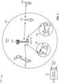
- Fig. 1 is a diagram illustrating a wireless network 100 in which aspects of the present disclosure may be practiced.
- the wireless network 100 may be an LTE network or some other wireless network, such as a 5G or NR network.
- the wireless network 100 may include a number of BSs 110 (shown as BS 110a, BS 110b, BS 110c, and BS 110d) and other network entities.
- a BS is an entity that communicates with user equipment (UEs) and may also be referred to as a base station, a NR BS, a Node B, a gNB, a 5G node B (NB), an access point, a transmit receive point (TRP), and/or the like.
- Each BS may provide communication coverage for a particular geographic area.
- the term "cell" can refer to a coverage area of a BS and/or a BS subsystem serving this coverage area, depending on the context in which the term is used.
- a BS may provide communication coverage for a macro cell, a pico cell, a femto cell, and/or another type of cell.
- a macro cell may cover a relatively large geographic area (e.g., several kilometers in radius) and may allow unrestricted access by UEs with service subscription.
- a pico cell may cover a relatively small geographic area and may allow unrestricted access by UEs with service subscription.
- a femto cell may cover a relatively small geographic area (e.g., a home) and may allow restricted access by UEs having association with the femto cell (e.g., UEs in a closed subscriber group (CSG)).
- a BS for a macro cell may be referred to as a macro BS.
- a BS for a pico cell may be referred to as a pico BS.
- a BS for a femto cell may be referred to as a femto BS or a home BS.
- a BS 110a may be a macro BS for a macro cell 102a
- a BS 110b may be a pico BS for a pico cell 102b
- a BS 110c may be a femto BS for a femto cell 102c.
- a BS may support one or multiple (e.g., three) cells.
- the terms "eNB”, “base station”, “NR BS”, “gNB”, “TRP”, “AP”, “node B", “5G NB”, and “cell” may be used interchangeably herein.
- a cell may not necessarily be stationary, and the geographic area of the cell may move according to the location of a mobile BS.
- the BSs may be interconnected to one another and/or to one or more other BSs or network nodes (not shown) in the wireless network 100 through various types of backhaul interfaces such as a direct physical connection, a virtual network, and/or the like using any suitable transport network.
- Wireless network 100 may also include relay stations.
- a relay station is an entity that can receive a transmission of data from an upstream station (e.g., a BS or a UE) and send a transmission of the data to a downstream station (e.g., a UE or a BS).
- a relay station may also be a UE that can relay transmissions for other UEs.
- a relay station 110d may communicate with macro BS 110a and a UE 120d in order to facilitate communication between BS 110a and UE 120d.
- a relay station may also be referred to as a relay BS, a relay base station, a relay, and/or the like.
- Wireless network 100 may be a heterogeneous network that includes BSs of different types, e.g., macro BSs, pico BSs, femto BSs, relay BSs, and/or the like. These different types of BSs may have different transmit power levels, different coverage areas, and different impacts on interference in wireless network 100.
- macro BSs may have a high transmit power level (e.g., 5 to 40 Watts) whereas pico BSs, femto BSs, and relay BSs may have lower transmit power levels (e.g., 0.1 to 2 Watts).
- a network controller 130 may couple to a set of BSs and may provide coordination and control for these BSs.
- Network controller 130 may communicate with the BSs via a backhaul.
- the BSs may also communicate with one another, e.g., directly or indirectly via a wireless or wireline backhaul.
- UEs 120 may be dispersed throughout wireless network 100, and each UE may be stationary or mobile.
- a UE may also be referred to as an access terminal, a terminal, a mobile station, a subscriber unit, a station, and/or the like.
- a UE may be a cellular phone (e.g., a smart phone), a personal digital assistant (PDA), a wireless modem, a wireless communication device, a handheld device, a laptop computer, a cordless phone, a wireless local loop (WLL) station, a tablet, a camera, a gaming device, a netbook, a smartbook, an ultrabook, a medical device or equipment, biometric sensors/devices, wearable devices (smart watches, smart clothing, smart glasses, smart wrist bands, smart jewelry (e.g., smart ring, smart bracelet)), an entertainment device (e.g., a music or video device, or a satellite radio), a vehicular component or sensor, smart meters/sensors, industrial manufacturing equipment, a global positioning system device, or any other suitable device that is configured to communicate via a wireless or wired medium.
- a cellular phone e.g., a smart phone
- PDA personal digital assistant
- WLL wireless local loop
- MTC and eMTC UEs include, for example, robots, drones, remote devices, sensors, meters, monitors, location tags, and/or the like, that may communicate with a base station, another device (e.g., remote device), or some other entity.
- a wireless node may provide, for example, connectivity for or to a network (e.g., a wide area network such as Internet or a cellular network) via a wired or wireless communication link.
- Some UEs may be considered Internet-of Things (IoT) devices, and/or may be implemented as NB-IoT (narrowband internet of things) devices.
- Some UEs may be considered a Customer Premises Equipment (CPE).
- UE 120 may be included inside a housing that houses components of UE 120, such as processor components, memory components, and/or the like.
- any number of wireless networks may be deployed in a given geographic area.
- Each wireless network may support a particular RAT and may operate on one or more frequencies.
- a RAT may also be referred to as a radio technology, an air interface, and/or the like.
- a frequency may also be referred to as a carrier, a frequency channel, and/or the like.
- Each frequency may support a single RAT in a given geographic area in order to avoid interference between wireless networks of different RATs.
- NR or 5G RAT networks may be deployed.
- two or more UEs 120 may communicate directly using one or more sidelink channels (e.g., without using a base station 110 as an intermediary to communicate with one another).
- the UEs 120 may communicate using peer-to-peer (P2P) communications, device-to-device (D2D) communications, a vehicle-to-everything (V2X) protocol (e.g., which may include a vehicle-to-vehicle (V2V) protocol, a vehicle-to-infrastructure (V2I) protocol, and/or the like), a mesh network, and/or the like).
- V2X vehicle-to-everything
- the UE 120 may perform scheduling operations, resource selection operations, and/or other operations described elsewhere herein as being performed by the base station 110.
- Fig. 1 is provided as an example. Other examples may differ from what is described with regard to Fig. 1 .
- Fig. 2 shows a block diagram of a design 200 of base station 110 and UE 120, which may be one of the base stations and one of the UEs in Fig. 1 .
- Base station 110 may be equipped with T antennas 234a through 234t
- UE 120 may be equipped with R antennas 252a through 252r, where in general T ⁇ 1 and R ⁇ 1.
- a transmit processor 220 may receive data from a data source 212 for one or more UEs, select one or more modulation and coding schemes (MCS) for each UE based at least in part on channel quality indicators (CQIs) received from the UE, process (e.g., encode and modulate) the data for each UE based at least in part on the MCS(s) selected for the UE, and provide data symbols for all UEs. Transmit processor 220 may also process system information (e.g., for semi-static resource partitioning information (SRPI) and/or the like) and control information (e.g., CQI requests, grants, upper layer signaling, and/or the like) and provide overhead symbols and control symbols.
- MCS modulation and coding schemes
- CQIs channel quality indicators
- Transmit processor 220 may also process system information (e.g., for semi-static resource partitioning information (SRPI) and/or the like) and control information (e.g., CQI requests, grants, upper layer signal
- Transmit processor 220 may also generate reference symbols for reference signals (e.g., the cell-specific reference signal (CRS)) and synchronization signals (e.g., the primary synchronization signal (PSS) and secondary synchronization signal (SSS)).
- a transmit (TX) multiple-input multiple-output (MIMO) processor 230 may perform spatial processing (e.g., precoding) on the data symbols, the control symbols, the overhead symbols, and/or the reference symbols, if applicable, and may provide T output symbol streams to T modulators (MODs) 232a through 232t. Each modulator 232 may process a respective output symbol stream (e.g., for OFDM and/or the like) to obtain an output sample stream.
- Each modulator 232 may further process (e.g., convert to analog, amplify, filter, and upconvert) the output sample stream to obtain a downlink signal.
- T downlink signals from modulators 232a through 232t may be transmitted via T antennas 234a through 234t, respectively.
- the synchronization signals can be generated with location encoding to convey additional information.
- antennas 252a through 252r may receive the downlink signals from base station 110 and/or other base stations and may provide received signals to demodulators (DEMODs) 254a through 254r, respectively.
- Each demodulator 254 may condition (e.g., filter, amplify, downconvert, and digitize) a received signal to obtain input samples.
- Each demodulator 254 may further process the input samples (e.g., for OFDM and/or the like) to obtain received symbols.
- a MIMO detector 256 may obtain received symbols from all R demodulators 254a through 254r, perform MIMO detection on the received symbols if applicable, and provide detected symbols.
- a receive processor 258 may process (e.g., demodulate and decode) the detected symbols, provide decoded data for UE 120 to a data sink 260, and provide decoded control information and system information to a controller/processor 280.
- a channel processor may determine reference signal received power (RSRP), received signal strength indicator (RSSI), reference signal received quality (RSRQ), channel quality indicator (CQI), and/or the like.
- RSRP reference signal received power
- RSSI received signal strength indicator
- RSRQ reference signal received quality indicator
- CQI channel quality indicator
- one or more components of UE 120 may be included in a housing.
- a transmit processor 264 may receive and process data from a data source 262 and control information (e.g., for reports comprising RSRP, RSSI, RSRQ, CQI, and/or the like) from controller/processor 280. Transmit processor 264 may also generate reference symbols for one or more reference signals. The symbols from transmit processor 264 may be precoded by a TX MIMO processor 266 if applicable, further processed by modulators 254a through 254r (e.g., for DFT-s-OFDM, CP-OFDM, and/or the like), and transmitted to base station 110.
- control information e.g., for reports comprising RSRP, RSSI, RSRQ, CQI, and/or the like
- Transmit processor 264 may also generate reference symbols for one or more reference signals.
- the symbols from transmit processor 264 may be precoded by a TX MIMO processor 266 if applicable, further processed by modulators 254a through 254r (e.g., for DFT-
- the uplink signals from UE 120 and other UEs may be received by antennas 234, processed by demodulators 232, detected by a MIMO detector 236 if applicable, and further processed by a receive processor 238 to obtain decoded data and control information sent by UE 120.
- Receive processor 238 may provide the decoded data to a data sink 239 and the decoded control information to controller/processor 240.
- Base station 110 may include communication unit 244 and communicate to network controller 130 via communication unit 244.
- Network controller 130 may include communication unit 294, controller/processor 290, and memory 292.
- Controller/processor 240 of base station 110, controller/processor 280 of UE 120, and/or any other component(s) of Fig. 2 may perform one or more techniques associated with reporting uplink control information (UCI) in a random access procedure, as described in more detail elsewhere herein.
- controller/processor 240 of base station 110, controller/processor 280 of UE 120, and/or any other component(s) of Fig. 2 may perform or direct operations of, for example, process 1000 of Fig. 10 , process 1100 of Fig. 11 , process 1200 of Fig. 12 , process 1300 of Fig. 13 , and/or other processes as described herein.
- Memories 242 and 282 may store data and program codes for base station 110 and UE 120, respectively.
- a scheduler 246 may schedule UEs for data transmission on the downlink and/or uplink.
- UE 120 may include means for transmitting an indication of a downlink beam in uplink control information of a random access message, wherein the downlink beam is different from a default beam corresponding to a preamble of the random access message and a random access occasion in which the random access message is transmitted, or wherein the downlink beam is selected from a set of multiple downlink beams corresponding to the random access occasion; means for monitoring for at least one of a random access response or a downlink communication subsequent to the random access response using the downlink beam indicated in the uplink control information; and/or the like.
- UE 120 may include means for transmitting at least one of a power headroom report or a buffer status report in uplink control information of a random access message; means for monitoring for at least one of a random access response or a downlink communication subsequent to the random access response based at least in part on the power headroom report or the buffer status report; and/or the like.
- such means may include one or more components of UE 120 described in connection with Fig. 2 .
- base station 110 may include means for receiving an indication of a downlink beam in uplink control information of a random access message, wherein the downlink beam is different from a default beam corresponding to a preamble of the random access message and a random access occasion associated with the random access message, or wherein the downlink beam is selected from a set of multiple downlink beams corresponding to the random access occasion; means for transmitting at least one of a random access response or a downlink communication subsequent to the random access response using the downlink beam indicated in the uplink control information; and/or the like.
- UE 120 may include means for receiving at least one of a power headroom report or a buffer status report in uplink control information of a random access message; means for transmitting at least one of a random access response or a downlink communication subsequent to the random access response based at least in part on the power headroom report or the buffer status report; and/or the like.
- such means may include one or more components of base station 110 described in connection with Fig. 2 .
- Fig. 2 is provided as an example. Other examples may differ from what is described with regard to Fig. 2 .
- Fig. 3 is a diagram illustrating an example 300 of a two-step random access channel (RACH) procedure. As shown in Fig. 3 , a base station 110 and a UE 120 may communicate with one another to perform the two-step RACH procedure.
- RACH random access channel
- the base station 110 may transmit, and the UE 120 may receive, one or more synchronization signal blocks (SSBs), system information (e.g., in one or more system information blocks (SIBs) and/or the like), and/or one or more reference signals (RSs) (e.g., channel state information reference signals (CSI-RSs) and/or the like).
- SSBs synchronization signal blocks
- RSs reference signals
- the UE 120 may perform downlink (DL) synchronization (such as by using one or more SSBs), may decode system information (SI) that is included in one or more SIBs, and/or may perform one or more measurements of the RS(s).
- DL downlink
- SI system information
- SI-RSs channel state information reference signals
- the UE 120 may determine parameters for transmitting a random access message (RAM) in the two-step RACH procedure. For example, the UE 120 may determine one or more physical random access channel (PRACH) transmission parameters to be used to transmit the RAM, may determine one or more parameters for generating a preamble of the RAM, may identify one or more uplink resources on which the RAM is to be transmitted, may determine a downlink beam for the RACH procedure (e.g., a default downlink beam and/or a preferred downlink beam), and/or the like.
- PRACH physical random access channel
- the UE 120 may transmit a RAM preamble.
- the UE 120 may transmit a RAM payload.
- the UE 120 may transmit the RAM preamble and the RAM payload as part of a first step of the two-step RACH procedure.
- the RAM is sometimes referred to as message A, msgA, or a first message in a two-step RACH procedure.
- the RAM preamble is sometimes referred to as a message A preamble, a msgA preamble, or a preamble.
- the RAM payload is sometimes referred to as a message A payload, a msgA payload, or a payload.
- the RAM may include some or all of the contents of message 1 (msg1) and message 3 (msg3) of a four-step RACH procedure.
- the RAM preamble may include some or all contents of message 1 (such as a RACH preamble).
- the RAM payload may include some or all contents of message 3 (such as a UE identifier, uplink control information, a physical uplink shared channel (PUSCH) communication, and/or the like).
- message 1 such as a RACH preamble
- PUSCH physical uplink shared channel
- the base station 110 may receive the RAM preamble transmitted by the UE 120. If the base station 110 successfully receives and decodes the RAM preamble, the base station 110 may then receive and decode the RAM payload.
- the base station 110 may transmit a random access response (RAR) (sometimes referred to as a RAR message). As shown, the base station 110 may transmit the RAR message as part of a second step of the two-step RACH procedure.
- RAR random access response
- the RAR message is sometimes referred to as message B, msgB, or a second message in a two-step RACH procedure.
- the RAR message may include some or all of the contents of message 2 (msg2) and message 4 (msg4) of a four-step RACH procedure.
- the RAR message may include the detected RACH preamble identifier, the detected UE identifier, a timing advance value, contention resolution information, and/or the like.
- Fig. 3 is provided as an example. Other examples may differ from what is described with regard to Fig. 3 .
- Fig. 4 is a diagram illustrating an example 400 of a random access message that includes a random access message preamble and a random access message payload.
- the RAM of the two-step RACH procedure may include a RAM preamble and a RAM payload, as described above.
- the RAM preamble may include a PRACH preamble signal and a guard time (shown as GT, with a duration of T G ).
- the RAM payload may include a demodulation reference signal (DMRS) and/or a physical uplink shared channel (PUSCH) communication, as well as a guard time (also shown as GT, with a duration of T G ).
- DMRS demodulation reference signal
- PUSCH physical uplink shared channel
- transmission of the RAM preamble and transmission of the RAM payload may be separated in time by a transmission guard time (shown as TxG, with a duration of T g ).
- performance of a wireless communication network may be improved by transmitting UCI, that may typically be transmitted after a RACH procedure is complete, in the RAM payload (e.g., in the PUSCH used for the RAM payload).
- UCI that may typically be transmitted after a RACH procedure is complete
- performance of the RACH procedure may be improved by such early reporting of UCI.
- Some techniques and apparatuses described herein permit a UE 120 to report a preferred downlink beam, a power headroom report, a buffer status report, and/or the like in UCI of a random access message (e.g., the RAM payload).
- a base station 110 may use this information to improve RACH communications and/or communications subsequent to the RACH procedure, such as by configuring and/or transmitting such communications based at least in part on the UCI received from the UE 120 in the random access message. Additional details are described below.
- Fig. 4 is provided as an example. Other examples may differ from what is described with regard to Fig. 4 .
- Fig. 5 is a diagram illustrating an example 500 of reporting UCI in a random access procedure, in accordance with various aspects of the present disclosure.
- a UE 120 and a base station 110 may communicate with one another to perform a 2-step RACH procedure.
- the base station 110 may transmit, and the UE 120 may receive, one or more SSBs, system information (e.g., in one or more (SIBs) and/or the like), and/or one or more RSs (e.g., CSI-RSs and/or the like).
- SIBs system information
- RSs e.g., CSI-RSs and/or the like
- different SSBs may be transmitted via different downlink beams, such as by using a beam-sweeping procedure.
- the UE 120 may determine a preferred downlink (DL) beam for communications with the base station 110 (e.g., for downlink communications from the base station 110 to the UE 120.
- the UE 120 may determine the preferred downlink beam based at least in part on the SSB(s), the CSI-RS(s), and/or the like.
- the UE 120 may measure one or more SSBs to determine an SSB with the best measurements, and may identify an SSB index of that SSB.
- the SSB index may correspond to a downlink beam via which the SSB was transmitted.
- the UE 120 may measure CSI-RS on one or more downlink beams, and may select a preferred downlink beam based at least in part on the measurements (e.g., the downlink beam with the best CSI-RS measurements).
- the UE 120 may identify a preferred downlink beam that is different from a default downlink beam associated with a preamble to be used by the UE 120 in a random access message (e.g., a RAM preamble) and/or associated with a random access occasion (e.g., one or more time resources, one or more frequency resources, and/or the like) in which the UE 120 is to transmit the random access message.
- a random access message e.g., a RAM preamble
- a random access occasion e.g., one or more time resources, one or more frequency resources, and/or the like
- a random access occasion may correspond to a single default downlink beam.
- the correspondence between random access occasions and default downlink beams may be indicated in system information, may be prespecified (e.g., according to a wireless communication standard), and/or the like.
- the base station 110 may transmit a random access response (e.g., msgB) via the default downlink beam corresponding to the random access occasion, and the UE 120 may monitor the default downlink beam for the random access response.
- the UE 120 can achieve early transmission of the random access message in a random access occasion corresponding to an optimal downlink beam identified by the UE 120 (e.g., the preferred downlink beam).
- the UE 120 is shown as identifying Beam 2 as the preferred downlink beam.
- Beam 1 may be the default downlink beam for the random access occasion (e.g., for all preambles, such as for 64 preambles when the UE 120 is permitted to select from a set of 64 preambles).
- the UE 120 selects Beam 2, which is different from the default downlink beam associated with the random access occasion.
- a random access occasion may correspond to multiple default downlink beams, and a set of preambles (e.g., random access preambles, RAM preambles, RACH preambles, and/or the like) may be partitioned into multiple subsets of preambles corresponding to the multiple default downlink beams.
- a default downlink beam and a corresponding combination of a random access occasion and a subset of preambles may be indicated in system information, may be prespecified, and/or the like.
- the base station 110 may transmit a random access response (e.g., msgB) via the default downlink beam corresponding to the random access occasion and the selected preamble, and the UE 120 may monitor the default downlink beam for the random access response.
- a random access message e.g., msgA
- msgB a random access response
- the UE 120 can achieve early transmission of the random access message in a random access occasion corresponding to an optimal downlink beam identified by the UE 120 (e.g., the preferred downlink beam). Furthermore, preamble partitioning can be avoided, thereby reducing the likelihood of a preamble collision.
- the UE 120 is shown as identifying Beam 2 as the preferred downlink beam.
- Beam 0 may be the default downlink beam for a first subset of preambles associated with the random access occasion (e.g., preambles 0 through 31)
- Beam 1 may be the default downlink beam for a second subset of preambles associated with the random access occasion (e.g., for preambles 32 through 63).
- the UE 120 selects Beam 2, which is different from the default downlink beam associated with the random access occasion.
- the UE 120 may select a preferred downlink beam from a set of multiple downlink beams associated with the random access occasion.
- preamble partitioning may be avoided by permitting the UE 120 to select any one of the multiple downlink beams and any preamble for the random access message.
- a downlink beam in the set of multiple downlink beams can be selected by the UE 120 regardless of a preamble selected by the UE 120.
- the correspondence between the random access occasion and the set of multiple downlink beams may be indicated in system information, may be prespecified (e.g., according to a wireless communication standard), and/or the like.
- the set of downlink beams associated with a selected random access occasion is shown as ⁇ Beam 1, Beam 2 ⁇ , representing Beam 1 and Beam 2.
- the UE 120 selects Beam 2 from the set (e.g., the UE 120 identifies Beam 2 as the preferred downlink beam).
- the UE 120 may identify the preferred downlink beam, and may then identify a random access occasion corresponding to a set of downlink beams that includes the preferred downlink beam.
- the UE 120 may transmit a random access message in the random access occasion (e.g., using any permitted preamble), and may indicate the preferred downlink beam in UCI of the random access message.
- the UE 120 may still need to wait for a random access occasion corresponding to a set of downlink beams that includes the preferred downlink beam, but such a wait may be reduced as compared to a scenario where each random access occasion corresponds to a single downlink beam. Furthermore, this configuration may reduce system complexity.
- the index may identify the preferred downlink beam from the set of multiple downlink beams (e.g., a first downlink beam in the set may be identified using a first index, a second downlink beam in the set may be identified using a second index, and so on).
- the base station 110 may transmit a random access response (RAR), such as msgB or msg2.
- RAR random access response
- the base station 110 may transmit the RAR on the preferred downlink beam indicated by the UE 120.
- the base station 110 may transmit the RAR on a default downlink beam associated with the random access occasion and/or the preamble used by the UE 120.
- the base station 110 may transmit the RAR on both the default downlink beam and the preferred downlink beam to achieve performance improvements associated with spatial diversity.
- the random access occasion may be associated with a set of multiple downlink beams (which may or may not include a default beam for the random access occasion), and the base station 110 may transmit the RAR on more than one downlink beam included in the set (e.g., on all downlink beams included in the set) to achieve performance improvements associated with spatial diversity.
- the base station 110 may transmit a subsequent DL communication using the preferred downlink beam indicated by the UE 120.
- the subsequent DL communication may include one or more messages that follow the RAR and/or that follow the RACH procedure, such as a physical downlink control channel (PDCCH) communication, a physical downlink shared channel (PDSCH) communication, a radio resource control (RRC) message (e.g., an RRC configuration message), and/or the like.
- PDCCH physical downlink control channel
- PDSCH physical downlink shared channel
- RRC radio resource control
- the UE 120 may monitor for the RAR on the default downlink beam and/or the preferred downlink beam, such as when the random access occasion is associated with a single default downlink beam.
- the UE 120 may be configured or required to monitor for the RAR on only the default downlink beam and not the preferred downlink beam.
- the default downlink beam may be used to transmit and/or receive the RAR
- the preferred downlink beam may be used to transmit and/or receive the one or more subsequent DL communications.
- the UE 120 may monitor for the RAR on only the preferred downlink beam and not the default downlink beam. However, in some cases, this may result in the UE 120 missing the RAR if the base station 110 could not decode the UCI indicating the preferred downlink beam, in which case the base station 110 may transmit the RAR on the default downlink beam. Thus, in some aspects, the UE 120 may monitor for the RAR on both the preferred downlink beam and the default downlink beam.
- the base station 110 may indicate (e.g., in system information, such as a SIB, remaining minimum system information (RMSI), and/or the like) a time division multiplexing (TDM) pattern to be used by the UE 120 to monitor different downlink beams for the RAR.
- the TDM pattern may indicate a first set of time domain resources (e.g., transmission time intervals (TTIs), such as slots, subframes, and/or the like) in which the default downlink beam is to be monitored, and may indicate a second set of time domain resources in which the preferred downlink beam is to be monitored.
- TTIs transmission time intervals
- the first set of time domain resources and the second set of time domain resources may be mutually exclusive.
- the first set of time domain resources may be even slots, and the second set of time domain resources may be odd slots, or vice versa.
- the UE 120 may monitor for the RAR on the preferred downlink beam and/or one or more other downlink beams included in a set of multiple downlink beams associated with a random access occasion.
- the UE 120 may be configured or required to monitor for the RAR on only the preferred downlink beam and not any other downlink beams included in the set. However, in some cases, this may result in the UE 120 missing the RAR if the base station 110 could not decode the UCI indicating the preferred downlink beam, in which case the base station 110 may transmit the RAR on a different downlink beam included in the set (e.g., the set could include a default beam and one or more other beams).
- the UE 120 may monitor for the RAR on the preferred downlink beam and one or more other downlink beams included in the set.
- the base station 110 may indicate a TDM pattern to be used by the UE 120 to monitor different downlink beams for the RAR.
- the TDM pattern may indicate a first set of time domain resources in which the preferred downlink beam is to be monitored, may indicate a second set of time domain resources in which another downlink beam in the set is to be monitored, and so on (e.g., for all or a subset of beams included in the set), in a similar manner as indicated above.
- the UE 120 may monitor for the subsequent DL communication(s) on the preferred downlink beam.
- the subsequent DL communication(s) may include one or more messages that follow the RAR and/or that follow the RACH procedure, such as a PDCCH communication, a PDSCH communication, an RRC message, and/or the like.
- the UE 120 may indicate multiple downlink beams (e.g., including a preferred downlink beam) in the UCI of the random access message. For example, the UE 120 may indicate a set of indexes corresponding to a set of beams. In some aspects, the UE 120 may indicate, in the UCI, a ranking for the set of indexes corresponding to the set of beams such that a list of beams from most-preferred to least-preferred is indicated to the base station 110.
- the UE 120 may determine whether to identify a beam in the list based at least in part on whether the beam satisfies a condition (e.g., a signal quality threshold, a signal power threshold, a reference signal received power (RSRP) threshold, a reference signal received quality (RSRQ) threshold, a signal-to-interference-plus-noise ratio (SINR) threshold, and/or the like).
- a condition e.g., a signal quality threshold, a signal power threshold, a reference signal received power (RSRP) threshold, a reference signal received quality (RSRQ) threshold, a signal-to-interference-plus-noise ratio (SINR) threshold, and/or the like.
- the list may include or may exclude a default beam associated with a random access occasion in which the random access message is transmitted.
- the UE 120 may indicate, in the UCI, one or more parameters for one or more of the beams included in the list, such as a measured signal quality, a measured signal power, a measured RSRP parameter, a measured RSRQ parameter, a measured SINR parameter, and/or the like. Additionally, or alternatively, the UE 120 may indicate, in the UCI, whether the beam corresponds to an SSB (and/or which SSB) or to a CSI-RS (and/or which CSI-RS) (e.g., if CSI-RS is configured for the UE 120.
- the base station 110 may send the RAR on multiple downlink beams (e.g., all indicated downlink beams or a subset of the multiple downlink beams) for spatial diversity gains.
- the UE 120 may be configured or required to monitor for the RAR on only a default downlink beam and not any other indicated beam.
- the default downlink beam may be used to transmit and/or receive the RAR, and one or more other downlink beams in the list (e.g., the best beam) may be used to transmit and/or receive the one or more subsequent DL communications.
- the base station 110 may indicate a set of downlink beams in the RAR.
- the set of downlink beams in the RAR may include all of the downlink beams indicated in the random access message or a subset of the downlink beams indicated in the random access message.
- the UE 120 may monitor the downlink beams indicated in the RAR according to a TDM pattern. As described above, in some aspects, the TDM pattern may be indicated in system information. Alternatively, the TDM pattern may be indicated in the RAR.
- the UE 120 may transmit a power headroom report (PHR) and/or a buffer status report (BSR) in the UCI of the random access message, as described in more detail elsewhere herein.
- the base station 110 may use the PHR and/or the BSR to configure and/or transmit the RAR and/or one or more subsequent downlink communications, as described in more detail elsewhere herein.
- Fig. 5 is provided as an example. Other examples may differ from what is described with regard to Fig. 5 .
- Fig. 6 is a diagram illustrating another example 600 of reporting UCI in a random access procedure, in accordance with various aspects of the present disclosure.
- a UE 120 and a base station 110 may communicate with one another to perform a 2-step RACH procedure (but may fall back to a 4-step RACH procedure in some aspects).
- the UE 120 may transmit an indication of the preferred downlink beam in UCI of a random access message (e.g., a first random access message), as described above in connection with Fig. 5 .
- a random access message e.g., a first random access message
- the base station 110 may receive the random access message, and may attempt to decode the random access message.
- the base station 110 may successfully decode the UCI (e.g., that indicates the preferred downlink beam), but may fail to successfully decode some other contents of the RAM payload (e.g., one or more media access control (MAC) protocol data units (PDUs) other than the UCI).
- MAC media access control
- the base station 110 may instruct the UE 120 to retransmit the random access message (e.g., as a retransmission of msgA of a 2-step RACH procedure) and/or to fall back to a 4-step RACH procedure (e.g., to transmit msg3 of a 4-step RACH procedure).
- the preferred downlink beam may be used for one or more messages of the RACH procedure that follow the initial random access message (e.g., transmitted in the first operation 605).
- the base station 110 may transmit a RAR (e.g., msg2 or msgB') via the preferred downlink beam, in a similar manner as described above in connection with Fig. 5 .
- the RAR e.g., a first RAR
- the RAR may include the instruction and/or an indication that the preferred downlink beam is to be used in association with the RACH procedure (e.g., for monitoring a PDCCH for retransmission of the random access message or for a new random access message, for a random access response to the retransmission or the new random access message, and/or the like).
- the base station 110 may transmit the RAR via a default downlink beam, and may use the preferred downlink beam for one or more RACH messages that occur after the RAR, in a similar manner as described above in connection with Fig. 5 .
- the base station 110 may transmit the RAR on both the default downlink beam and the preferred downlink beam to achieve performance improvements associated with spatial diversity.
- the UE 120 may perform PDCCH monitoring for an additional random access message based at least in part on the preferred downlink beam. For example, the UE 120 may monitor for the PDCCH on the preferred downlink beam.
- the base station 110 may transmit a PDCCH communication on the preferred downlink beam, and the UE 120 may receive the PDCCH communication on the preferred downlink beam.
- the PDCCH communication may include DCI for transmission of a new RAM (e.g., a retransmission of msgA of 2-step RACH or a new transmission of msg3 of 4-step RACH), such as a resource allocation for the new RAM, an MCS for the new RAM, a timing advance for the new RAM, and/or the like.
- a new RAM e.g., a retransmission of msgA of 2-step RACH or a new transmission of msg3 of 4-step RACH
- a new RAM e.g., a retransmission of msgA of 2-step RACH or a new transmission of msg3 of 4-step RACH
- a new RAM e.g., a retransmission of msgA of 2-step RACH or a new transmission of msg3 of 4-step RACH
- the UE 120 may transmit another RAM (e.g., a second RAM) to the base station 110.
- the second RAM may be a retransmission of the first RAM (e.g., msgA) transmitted in the first operation 605 when the UE 120 continues to perform the 2-step RACH procedure, or may be an initial transmission of a random access message (e.g., msg3) of a 4-step RACH procedure when the UE 120 falls back to the 4-step RACH procedure.
- the UE 120 may transmit the second RAM based at least in part on a PDCCH communication, which may be received via the preferred downlink beam.
- the base station 110 may transmit an additional RAR.
- the base station 110 may transmit the additional RAR (e.g., and/or one or more subsequent RARs if there are additional failures) if a time period associated with RAR transmissions has not elapsed.
- the UE 120 may continue to monitor for RARs until the end of the time period (e.g., the end of a RAR window).
- a later-received RAR in the time period may override an earlier-received RAR in the time period.
- the UE 120 may reset a contention resolution timer (e.g., associated with the RAR window) to permit reception of additional RARs upon additional failures.
- the UE 120 may monitor multiple beams during the time period when RARs are transmitted via the default beam. For example, the UE 120 may monitor for a RAR on the default beam, and may monitor for PDCCH (as described above in operation 620) on the preferred beam.
- the base station 110 may transmit another RAR (e.g., a second RAR).
- the second RAR may be transmitted via the preferred downlink beam.
- the second RAR may include all or a portion of msgB when the UE 120 and the base station 110 continue to perform a 2-step RACH procedure, or may be msg4 of a 4-step RACH procedure when the UE 120 and the base station 110 fall back to the 4-step RACH procedure.
- the UE 120 may monitor for the second RAR based at least in part on the preferred downlink beam. For example, the UE 120 may perform PDCCH monitoring and/or PDSCH monitoring for the second RAR based on the preferred downlink beam.
- communications via the preferred beam may have a higher throughput, a lower latency, a higher reliability, and/or the like as compared to communications via a non-preferred beam.
- Fig. 6 is provided as an example. Other examples may differ from what is described with regard to Fig. 6 .
- Fig. 7 is a diagram illustrating another example 700 of reporting UCI in a random access procedure, in accordance with various aspects of the present disclosure.
- a base station 110 may communicate with multiple UEs 120, shown as UE A (e.g., a first UE 120) and UE B (e.g., a second UE 120).
- the base station 110 and the UEs 120 may communicate to perform a 2-step RACH procedure.
- UE A may transmit a random access message indicating, in UCI of the random access message, a preferred downlink beam (and/or indicating a PHR, a BSR, and/or the like).
- the content of the UCI transmitted by UE A is represented as UCI A.
- UE A may transmit the random access preamble on a first set of resources (e.g., time resources, frequency resources, spatial resources, and/or the like), represented as Resource(s) A.
- UE A may select a preamble for the random access message, represented by a random access preamble identifier (RAPID) of 1.
- RAPID random access preamble identifier
- UE B may also transmit a random access message indicating, in UCI of the random access message, a preferred downlink beam (and/or indicating a PHR, a BSR, and/or the like).
- the content of the UCI transmitted by UE B is represented as UCI B.
- UE B may transmit the random access preamble on a second set of resources (e.g., time resources, frequency resources, spatial resources, and/or the like), represented as Resource(s) B.
- the second set of resources may be the same as and/or may overlap with the first set of resources, or may be different from and/or non-overlapping with the first set of resources.
- UE B may select the same preamble for the random access message as the preamble selected by UE A, shown as RAPID 1. As a result, the random access messages of UE A and UE B may collide.
- the base station 110 may detect the collision. Based at least in part on detecting the collision, the base station 110 may transmit one or more random access responses (RARs) that include collision mitigation information.
- the collision mitigation information included in a RAR may include, for example, a RAPID and UCI (e.g., all of the UCI or a portion of the UCI) transmitted in a random access message corresponding to the RAR, an RAPID and information that identifies one or more resources used for the UCI transmitted in the random access message corresponding to the RAR, an RAPID and a hashing identifier that is generated based at least in part on the UCI and/or the one or more resources, and/or the like.
- a UE 120 may identify information (e.g., downlink control information (DCI)) relating to a subsequent random access message (e.g., msg3 and/or a retransmission of msgA) by analyzing contents of multiple RARs to identify a RAR corresponding to the UE 120. For example, if the RAR includes an RAPID and UCI for a corresponding random access message, the UE 120 may determine whether the UCI in the RAR matches UCI transmitted by the UE 120 in the random access message.
- DCI downlink control information
- the UE 120 may determine that the RAR is intended for the UE 120, and may use information in the RAR (e.g., DCI for a subsequent communication, a timing advance value, a resource allocation, and/or the like) to communicate with the base station 110. If the UCI does not match, then the UE 120 may continue to monitor for a RAR corresponding to the UE 120 (or may restart a RACH procedure if a RAR for the UE 120 is not received within a time window).
- information in the RAR e.g., DCI for a subsequent communication, a timing advance value, a resource allocation, and/or the like
- the UE 120 may determine whether the resources indicated in the RAR match the resources used by the UE 120 to transmit the UCI. If the resources match, then the UE 120 may determine that the RAR is intended for the UE 120, and may use information in the RAR to communicate with the base station 110. If the resources do not match, then the UE 120 may continue to monitor for a RAR corresponding to the UE 120 (or may restart a RACH procedure if a RAR for the UE 120 is not received within a time window).
- the UE 120 may determine whether the hashing identifier indicated in the RAR (e.g., which is generated by the base station 110) matches a hashing identifier generated by the UE 120 (e.g., using a same hashing algorithm as the base station 110). If the hashing identifiers match, then the UE 120 may determine that the RAR is intended for the UE 120, and may use information in the RAR to communicate with the base station 110. If the hashing identifiers do not match, then the UE 120 may continue to monitor for a RAR corresponding to the UE 120 (or may restart a RACH procedure if a RAR for the UE 120 is not received within a time window).
- the RAR may indicate a dedicated preamble and/or a dedicated random access occasion to be used by a UE 120 for a subsequent RACH attempt (e.g., retransmission of a random access message).
- the base station 110 may assign a first preamble to a first UE 120, and may assign a second (different) preamble to a second UE 120 based at least in part on detecting a collision between a random access message from the first UE 120 and a random access message from the second UE 120.
- the base station 110 may assign a first random access occasion to a first UE 120, and may assign a second (different) random access occasion to a second UE 120 based at least in part on detecting the collision.
- a UE 120 may use a dedicated preamble and/or a dedicated random access occasion indicated by the base station 110 for a retransmission of the random access message.
- a random access radio network temporary identifier (RA-RNTI) used by a UE 120 may be generated based at least in part on a preamble selected by the UE 120 and a PUSCH occasion selected by the UE 120 for transmission of the random access message.
- RA-RNTI radio network temporary identifier
- Using the techniques described above may reduce the likelihood of random access message collisions, mitigate random access message collisions after such collisions have occurred, and/or permit earlier detection of random access message collisions, thereby improving network performance.
- Fig. 7 is provided as an example. Other examples may differ from what is described with regard to Fig. 7 .
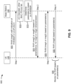
- Fig. 8 is a diagram illustrating another example 800 of reporting UCI in a random access procedure, in accordance with various aspects of the present disclosure. As shown in Fig. 8 , a UE 120 and a base station 110 may communicate with one another to perform a 2-step RACH procedure.
- the UE 120 may transmit a power headroom report (PHR) and/or a buffer status report (BSR) in UCI of a random access message.
- the random access message may be msgA, and may include a RAM preamble and a RAM payload.
- the UE 120 may transmit the PHR and/or the BSR in the RAM payload, such as in UCI of the RAM payload (e.g., in a PUSCH communication included in the RAM payload).
- the UE 120 may transmit the PHR and/or the BSR in the UCI, and may not transmit the preferred downlink beam (as described above) in the UCI.
- the UE 120 may indicate the preferred downlink beam and at least one of the PHR and/or the BSR in the UCI.
- one or more indexes and/or values to be used to report the PHR and/or the BSR may be indicated to the UE 120 in system information (e.g., RMSI and/or the like).
- the base station 110 may determine one or more parameters for a RAR and/or one or more subsequent downlink communications based at least in part on the PHR and/or the BSR.
- the one or more subsequent downlink communications may include one or more messages that follow the RAR and/or that follow the RACH procedure, such as a PDCCH communication (e.g., for uplink scheduling), a PDSCH communication, an RRC message, and/or the like.
- the one or more parameters may include, for example, a resource allocation for a communication (e.g., a set of time domain, frequency domain, and/or spatial domain resources), an MCS for the communication, a layer configuration for the communication (e.g., a number of MIMO layers to be used for the communication, one or more layer indexes, and/or the like), and/or the like.
- a resource allocation for a communication e.g., a set of time domain, frequency domain, and/or spatial domain resources
- an MCS for the communication e.g., a set of time domain, frequency domain, and/or spatial domain resources
- a layer configuration for the communication e.g., a number of MIMO layers to be used for the communication, one or more layer indexes, and/or the like
- the base station 110 may determine a layer configuration and/or an MCS based at least in part on the PHR.
- the PHR may indicate whether the UE 120 has additional power headroom to support additional and/or multiple layers, whether the UE 120 has additional power headroom to support a different and/or a higher MCS, and/or the like.
- the base station 110 may determine a resource allocation based at least in part on the BSR.
- the BSR may indicate an amount of data queued for transmission by the UE 120, which may indicate a number of resources needed for the transmission.
- the base station 110 may configure an appropriate resource allocation for the UE 120.
- the base station 110 may transmit a RAR, in a similar manner as described elsewhere herein.
- the base station 110 may transmit the one or more subsequent downlink communications, in a similar manner as described elsewhere herein.
- at least one of the RAR or the one or more subsequent downlink communications may be based at least in part on the PHR and/or the BSR.
- the base station 110 may determine a layer configuration and/or an MCS for the RAR and/or the one or more subsequent downlink communications based at least in part on the PHR and/or the BSR.
- the base station 110 may determine a resource allocation to be indicated to the UE 120 in an uplink grant (e.g., in the RAR and/or in a subsequent downlink communication).
- the UE 120 may monitor for a RAR and/or a downlink communication subsequent to the RAR based at least in part on the PHR and/or the BSR.
- the UE 120 may monitor for a communication based at least in part on a layer configuration, an MCS, and/or the like, which may be based at least in part on the PHR and/or the BSR and/or which may be indicated to the UE 120 by the base station 110 based at least in part on the PHR and/or the BSR.
- performance may be improved.
- the base station 110 may configure one or more communications using the PHR and/or the BSR to achieve higher throughput, lower latency, higher reliability, and/or the like as compared to configuring such communication(s) without using the PHR and/or the BSR.
- Fig. 8 is provided as an example. Other examples may differ from what is described with regard to Fig. 8 .
- Fig. 9 is a diagram illustrating another example 900 of reporting UCI in a random access procedure, in accordance with various aspects of the present disclosure.
- a UE 120 and a base station 110 may communicate with one another to perform a 2-step RACH procedure (but may fall back to a 4-step RACH procedure in some aspects).
- the UE 120 may transmit a PHR and/or a BSR in UCI of a random access message (e.g., a first random access message), as described above in connection with Fig. 8 .
- a random access message e.g., a first random access message
- the base station 110 may receive the random access message, and may attempt to decode the random access message.
- the base station 110 may successfully decode the UCI (e.g., that indicates the PHR and/or the BSR), but may fail to successfully decode some other contents of the RAM payload (e.g., one or more MAC PDUs other than the UCI).
- the base station 110 may determine one or more parameters, associated with a RAR to be transmitted by the base station 110, based at least in part on the PHR and/or the BSR.
- the one or more parameters may relate to an uplink grant to be included in a RAR.
- the base station 110 calculate one or more parameters for the uplink grant (e.g., a resource allocation, a layer configuration, an MCS, and/or the like) based at least in part on the PHR and/or the BSR, in a similar manner as described above in connection with Fig. 8 .
- the uplink grant may be an uplink grant associated with a 4-step RACH procedure, and the RAR may instruct the UE 120 to fall back to the 4-step RACH procedure and to use the uplink grant for transmission of msg3. Additionally, or alternatively, the RAR may instruct the UE 120 to retransmit the random access message (e.g., as part of a continued 2-step RACH procedure).
- the RAR may indicate an MCS, a resource allocation (e.g., a PUSCH resource allocation), and/or a layer configuration for the retransmission.
- the base station 110 may transmit the RAR to the UE 120.
- the RAR may include msg2 or msgB', depending on whether the 2-step RACH procedure is to continue or whether the UE 120 and the base station 110 are to fall back to the 4-step RACH procedure.
- the RAR may include an uplink grant for msg3, and the uplink grant may indicate and/or may be determined based at least in part on one or more parameters that are determined based at least in part on the PHR and/or the BSR.
- the RAR may instruct the UE 120 to retransmit the random access message, and may include one or more parameters for the retransmission.
- the UE 120 may transmit a second random access message to the base station 110.
- the second RAM may be a retransmission of the first RAM (e.g., msgA) transmitted in the first operation 905 when the UE 120 continues to perform the 2-step RACH procedure, or may be an initial transmission of a random access message (e.g., msg3) of a 4-step RACH procedure when the UE 120 falls back to the 4-step RACH procedure.
- the UE 120 may transmit the second RAM based at least in part on one or more parameters indicated in the RAR. For example, the UE 120 may transmit the RAM using a resource allocation, a layer configuration, and/or an MCS indicated in the RAR.
- the base station 110 may transmit a second RAR.
- the second RAR may include all or a portion of msgB when the UE 120 and the base station 110 continue to perform a 2-step RACH procedure, or may be msg4 of a 4-step RACH procedure when the UE 120 and the base station 110 fall back to the 4-step RACH procedure.
- the second RAR may be transmitted based at least in part on the one or more parameters (e.g., using a resource allocation, an MCS, a layer configuration, and/or the like determined based at least in part on the PHR and/or the BSR).
- the UE 120 may monitor for the second RAR based at least in part on the one or more parameters. For example, the UE 120 may perform PDCCH monitoring and/or PDSCH monitoring for the second RAR using an indicated resource allocation, MCS, and/or the layer configuration.
- performance may be improved.
- the base station 110 may configure one or more communications using the PHR and/or the BSR to achieve higher throughput, lower latency, higher reliability, and/or the like as compared to configuring such communication(s) without using the PHR and/or the BSR.
- Fig. 9 is provided as an example. Other examples may differ from what is described with regard to Fig. 9 .
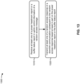
- Fig. 10 is a diagram illustrating an example process 1000 performed, for example, by a UE, in accordance with various aspects of the present disclosure.
- Example process 1000 is an example where a UE (e.g., UE 120 and/or the like) performs operations associated with reporting uplink control information in a random access procedure.
- a UE e.g., UE 120 and/or the like
- process 1000 may include transmitting an indication of a downlink beam in uplink control information of a random access message, wherein the downlink beam is different from a default beam corresponding to a preamble of the random access message and a random access occasion in which the random access message is transmitted, or wherein the downlink beam is selected from a set of multiple downlink beams corresponding to the random access occasion (block 1010).
- the UE e.g., using transmit processor 264, controller/processor 280, memory 282, and/or the like
- the downlink beam is different from a default beam corresponding to a preamble of the random access message and a random access occasion in which the random access message is transmitted. In some aspects, the downlink beam is selected from a set of multiple downlink beams corresponding to the random access occasion.
- process 1000 may include monitoring for at least one of a random access response or a downlink communication subsequent to the random access response using the downlink beam indicated in the uplink control information (block 1020).
- the UE e.g., using receive processor 258, controller/processor 280, memory 282, and/or the like
- Process 1000 may include additional aspects, such as any single aspect or any combination of aspects described below and/or in connection with one or more other processes described elsewhere herein.
- a plurality of random access occasions configured for the UE each correspond to a single default beam, wherein the downlink beam is different from the default beam corresponding to the random access occasion in which the random access message is transmitted.
- a plurality of random access occasions configured for the UE each correspond to multiple default beams, wherein the multiple default beams are each associated with a different set of preambles, wherein the downlink beam is different from the default beam corresponding to the random access occasion in which the random access message is transmitted and corresponding to the preamble of the random access message.
- the random access response is received via the default beam or via the downlink beam.
- process 1000 includes monitoring at least one of the default beam or the downlink beam based at least in part on a time division multiplexing pattern indicated in system information.
- the default beam is monitored for the random access response and the downlink beam is monitored for the downlink communication subsequent to the random access response.
- the downlink beam is indicated using an index that identifies the downlink beam from the set of multiple downlink beams corresponding to the random access occasion.
- a set of preambles is not partitioned among different downlink beams included in the set of multiple downlink beams.
- process 1000 includes monitoring at least one of the downlink beam or another downlink beam included in the set of multiple downlink beams based at least in part on a time division multiplexing pattern indicated in system information.
- the random access message is associated with a two-step random access channel procedure and the random access response instructs the UE to use the downlink beam in association with a retransmission of the random access response or to fall back to a four-step random access channel procedure.
- the UE is configured to monitor for random access responses until an end of a random access response window.
- the random access response includes at least one of: a random access preamble identifier and the uplink control information transmitted in the random access message, a random access preamble identifier and information that identifies one or more resources used for the uplink control information transmitted in the random access message, or a random access preamble identifier and a hashing identifier that is based at least in part on at least one of the uplink control information or the one or more resources.
- a random access radio network temporary identifier for the UE is based at least in part on the preamble of the random access message and a physical uplink shared channel occasion in which the random access message is transmitted.
- the random access response identifies at least one of a dedicated preamble or a dedicated random access occasion to be used by the UE for a subsequent random access message.
- the downlink beam is one of a plurality of downlink beams indicated in the uplink control information of the random access message.
- process 1000 includes monitoring at least one of the plurality of downlink beams based at least in part on a time division multiplexing pattern indicated in system information.
- the random access response indicates a set of downlink beams to be monitored by the UE and a time division multiplexing pattern for monitoring the set of downlink beams.
- the uplink control information further includes at least one of a power headroom report or a buffer status report.
- process 1000 may include additional blocks, fewer blocks, different blocks, or differently arranged blocks than those depicted in Fig. 10 . Additionally, or alternatively, two or more of the blocks of process 1000 may be performed in parallel.
- Fig. 11 is a diagram illustrating an example process 1100 performed, for example, by a UE, in accordance with various aspects of the present disclosure.
- Example process 1100 is an example where a UE (e.g., UE 120 and/or the like) performs operations associated with reporting uplink control information in a random access procedure.
- a UE e.g., UE 120 and/or the like
- process 1100 may include transmitting at least one of a power headroom report or a buffer status report in uplink control information of a random access message (block 1110).
- the UE e.g., using transmit processor 264, controller/processor 280, memory 282, and/or the like
- process 1100 may include monitoring for at least one of a random access response or a downlink communication subsequent to the random access response based at least in part on the power headroom report or the buffer status report (block 1120).
- the UE e.g., using receive processor 258, controller/processor 280, memory 282, and/or the like
- Process 1100 may include additional aspects, such as any single aspect or any combination of aspects described below and/or in connection with one or more other processes described elsewhere herein.
- the random access message is associated with a two-step random access channel procedure and the random access response includes an uplink grant for retransmission of the random access message or fallback to a four-step random access channel procedure, wherein the uplink grant is determined based at least in part on at least one of the power headroom report or the buffer status report.
- the random access response indicates one or more parameters for a retransmission of the random access message, wherein the one or more parameters are determined based at least in part on at least one of the power headroom report or the buffer status report.
- the one or more parameters include at least one of a resource allocation, a modulation and coding scheme, or a layer configuration.
- the random access response includes at least one of: a random access preamble identifier and the uplink control information transmitted in the random access message, a random access preamble identifier and information that identifies one or more resources used for the uplink control information transmitted in the random access message, or a random access preamble identifier and a hashing identifier that is based at least in part on at least one of the uplink control information or the one or more resources.
- a random access radio network temporary identifier for the UE is based at least in part on a preamble of the random access message and a random access occasion in which the random access message is transmitted.
- the random access response identifies at least one of a dedicated preamble or a dedicated random access occasion to be used by the UE for a subsequent random access message.
- the uplink control information further indicates a downlink beam, wherein the downlink beam is different from a default beam corresponding to a preamble of the random access message and a random access occasion in which the random access message is transmitted, or wherein the downlink beam is selected from a set of multiple downlink beams corresponding to the random access occasion.
- process 1100 may include additional blocks, fewer blocks, different blocks, or differently arranged blocks than those depicted in Fig. 11 . Additionally, or alternatively, two or more of the blocks of process 1100 may be performed in parallel.
- Fig. 12 is a diagram illustrating an example process 1200 performed, for example, by a base station, in accordance with various aspects of the present disclosure.
- Example process 1200 is an example where a base station (e.g., base station 110 and/or the like) performs operations associated with reporting uplink control information in a random access procedure.
- a base station e.g., base station 110 and/or the like
- process 1200 may include receiving an indication of a downlink beam in uplink control information of a random access message, wherein the downlink beam is different from a default beam corresponding to a preamble of the random access message and a random access occasion associated with the random access message, or wherein the downlink beam is selected from a set of multiple downlink beams corresponding to the random access occasion (block 1210).
- the base station e.g., using receive processor 238, controller/processor 240, memory 242, and/or the like
- the downlink beam is different from a default beam corresponding to a preamble of the random access message and a random access occasion associated with the random access message. In some aspects, the downlink beam is selected from a set of multiple downlink beams corresponding to the random access occasion.
- process 1200 may include transmitting at least one of a random access response or a downlink communication subsequent to the random access response using the downlink beam indicated in the uplink control information (block 1220).
- the base station e.g., using transmit processor 220, controller/processor 240, memory 242, and/or the like
- Process 1200 may include additional aspects, such as any single aspect or any combination of aspects described below and/or in connection with one or more other processes described elsewhere herein.
- a plurality of random access occasions each correspond to a single default beam, wherein the downlink beam is different from the default beam corresponding to the random access occasion in which the random access message is transmitted.
- a plurality of random access occasions each correspond to multiple default beams, wherein the multiple default beams are each associated with a different set of preambles, wherein the downlink beam is different from the default beam corresponding to the random access occasion in which the random access message is transmitted and corresponding to the preamble of the random access message.
- the random access response is transmitted via the default beam or via the downlink beam.
- process 1200 includes transmitting, in system information, a time division multiplexing pattern to be used for monitoring at least one of the default beam or the downlink beam.
- the random access response is transmitted via the default beam and the downlink communication subsequent to the random access response is transmitted via the downlink beam.
- the downlink beam is indicated using an index that identifies the downlink beam from the set of multiple downlink beams corresponding to the random access occasion.
- a set of preambles is not partitioned among different downlink beams included in the set of multiple downlink beams.
- process 1200 includes transmitting, in system information, a time division multiplexing pattern to be used for monitoring at least one of the downlink beam or another downlink beam included in the set of multiple downlink beams.
- the random access message is associated with a two-step random access channel procedure and the random access response includes an instruction to use the downlink beam in association with a retransmission of the random access response or to fall back to a four-step random access channel procedure.
- the base station is configured to retransmit random access responses upon detecting a failure until an end of a random access response window.
- the random access response includes at least one of: a random access preamble identifier and the uplink control information received in the random access message, a random access preamble identifier and information that identifies one or more resources used for the uplink control information received in the random access message, or a random access preamble identifier and a hashing identifier that is based at least in part on at least one of the uplink control information or the one or more resources.
- a random access radio network temporary identifier is generated based at least in part on the preamble of the random access message and a physical uplink shared channel occasion in which the random access message is transmitted.
- the random access response identifies at least one of a dedicated preamble or a dedicated random access occasion to be used for a subsequent random access message.
- the downlink beam is one of a plurality of downlink beams indicated in the uplink control information of the random access message.
- process 1200 includes transmitting, in system information, a time division multiplexing pattern for monitoring at least one of the plurality of downlink beams.
- the random access response indicates a set of downlink beams to be monitored and a time division multiplexing pattern for monitoring the set of downlink beams.
- the uplink control information further includes at least one of a power headroom report or a buffer status report.
- process 1200 may include additional blocks, fewer blocks, different blocks, or differently arranged blocks than those depicted in Fig. 12 . Additionally, or alternatively, two or more of the blocks of process 1200 may be performed in parallel.
- Fig. 13 is a diagram illustrating an example process 1300 performed, for example, by a base station, in accordance with various aspects of the present disclosure.
- Example process 1300 is an example where a base station (e.g., base station 110 and/or the like) performs operations associated with reporting uplink control information in a random access procedure.
- a base station e.g., base station 110 and/or the like
- process 1300 may include receiving at least one of a power headroom report or a buffer status report in uplink control information of a random access message (block 1310).
- the base station e.g., using receive processor 238, controller/processor 240, memory 242, and/or the like
- process 1300 may include transmitting at least one of a random access response or a downlink communication subsequent to the random access response based at least in part on the power headroom report or the buffer status report (block 1320).
- the base station e.g., using transmit processor 220, controller/processor 240, memory 242, and/or the like
- Process 1300 may include additional aspects, such as any single aspect or any combination of aspects described below and/or in connection with one or more other processes described elsewhere herein.
- the one or more parameters include at least one of a resource allocation, a modulation and coding scheme, or a layer configuration.
- the uplink control information further indicates a downlink beam, wherein the downlink beam is different from a default beam corresponding to a preamble of the random access message and a random access occasion in which the random access message is transmitted, or wherein the downlink beam is selected from a set of multiple downlink beams corresponding to the random access occasion.
- process 1300 may include additional blocks, fewer blocks, different blocks, or differently arranged blocks than those depicted in Fig. 13 . Additionally, or alternatively, two or more of the blocks of process 1300 may be performed in parallel.
- ком ⁇ онент is intended to be broadly construed as hardware, firmware, and/or a combination of hardware and software.
- a processor is implemented in hardware, firmware, and/or a combination of hardware and software.
- satisfying a threshold may, depending on the context, refer to a value being greater than the threshold, greater than or equal to the threshold, less than the threshold, less than or equal to the threshold, equal to the threshold, not equal to the threshold, and/or the like.
Landscapes
- Engineering & Computer Science (AREA)
- Computer Networks & Wireless Communication (AREA)
- Signal Processing (AREA)
- Mobile Radio Communication Systems (AREA)
Claims (12)
- Ein Verfahren (1000) für eine drahtlose Kommunikation, das durch ein Benutzergerät (User Equipment bzw. UE) durchgeführt wird, aufweisend:Senden (1010) einer Angabe, die einen Satz von Indizes in Entsprechung zu einem Satz von Abwärtsstrecke-Strahlen in Aufwärtsstrecke-Steuerinformationen einer Direktzugriffsnachricht enthält, wobei jeder Abwärtsstrecke-Strahl aus dem Satz von Abwärtsstrecke-Strahlen verschieden von einem Standardstrahl in Entsprechung zu einer Präambel der Direktzugriffsnachricht und einer Direktzugriffsgelegenheit, in der die Direktzugriffsnachricht gesendet wird, ist oder wobei jeder Abwärtsstreckestrahl aus dem Satz von Abwärtsstreckestrahlen aus einem Satz von mehreren Abwärtsstreckestrahlen in Entsprechung zu der Direktzugriffsgelegenheit ausgewählt wird, undÜberwachen (1020) auf wenigstens eine Direktzugriffsantwort oder eine auf die Direktzugriffsantwort folgende Abwärtsstreckekommunikation, die den in den Aufwärtsstrecke-Steuerinformationen angegebenen Abwärtsstreckestrahl verwendet, wobei der Abwärtsstreckestrahl einer aus einer Vielzahl von in den Aufwärtstrecke-Steuerinformationen der Direktzugriffsnachricht angegebenen Abwärtsstreckestrahlen ist, wobei die Direktzugriffsnachricht mit einer zweistufigen Direktzugriffskanalprozedur assoziiert ist und die Direktzugriffsantwort das UE für ein Zurückfallen auf eine vierstufige Direktzugriffskanalprozedur anweist.
- Verfahren nach Anspruch 1, wobei eine Vielzahl von für das UE konfigurierten Direktzugriffsgelegenheiten jeweils einem einzelnen Standardstrahl entsprechen und wobei der Abwärtsstreckestrahl verschieden von dem Standardstrahl in Entsprechung zu der Direktzugriffsgelegenheit, in der die Direktzugriffsnachricht gesendet wird, ist.
- Verfahren nach Anspruch 1, wobei eine Vielzahl von für das UE konfigurierten Direktzugriffsgelegenheiten jeweils mehreren Standardstrahlen entsprechen, wobei die mehreren Standardstrahlen jeweils mit einem anderen Satz von Präambeln assoziiert sind und wobei der Abwärtsstreckestrahl verschieden von dem Standardstrahl in Entsprechung zu der Direktzugriffsgelegenheit, in der die Direktzugriffsnachricht gesendet wird, und in Entsprechung zu der Präambel der Direktzugriffsnachricht ist.
- Verfahren nach Anspruch 1, wobei die Direktzugriffsantwort über den Standardstrahl oder über den Abwärtsstreckestrahl empfangen wird.
- Verfahren nach Anspruch 1, das weiterhin das Überwachen des Standardstrahls und/oder des Abwärtsstreckestrahls basierend wenigstens teilweise auf einem in Systeminformationen angegebenen Zeitmultiplexmuster aufweist.
- Verfahren nach Anspruch 1, wobei der Standardstrahl auf die Direktzugriffsantwort überwacht wird und der Abwärtsstreckestrahl auf die auf die Direktzugriffsantwort folgende Abwärtsstreckekommunikation überwacht wird.
- Verfahren nach Anspruch 1, wobei ein Satz von Präambeln nicht auf verschiedene in dem Satz von mehreren Abwärtsstreckestrahlen enthaltene Abwärtsstreckestrahlen aufgeteilt wird.
- Verfahren nach Anspruch 1, das weiterhin das Überwachen des Abwärtsstreckestrahls oder eines anderen Abwärtsstreckestrahls in dem Satz von mehreren Abwärtsstreckestrahlen basierend wenigstens teilweise auf einem in Systeminformationen enthaltenen Zeitmultiplexmuster aufweist.
- Verfahren nach Anspruch 1, wobei das UE konfiguriert ist zum Überwachen auf Direktzugriffsantworten bis zu einem Ende eines Direktzugriffsanwortfensters.
- Verfahren nach Anspruch 1, wobei die Direktzugriffsantwort wenigstens eines der Folgenden enthält:eine Direktzugriffs-Präambelkennung und die in der Direktzugriffsnachricht gesendeten Aufwärtsstrecke-Steuerinformationen,eine Direktzugriffs-Präambelkennung und Informationen, die eine oder mehrere für die in der Direktzugriffsnachricht gesendeten Aufwärtstrecke-Steuerinformationen verwendete Ressourcen angeben, odereine Direktzugriffs-Präambelkennung und eine Hash-Kennung, die wenigstens teilweise auf den Aufwärtsstrecke-Steuerinformationen und/oder der einen oder den mehreren Ressourcen basiert.
- Verfahren nach Anspruch 1, wobei eine Direktzugriff-Funknetz-Temporärkennung für das UE wenigstens teilweise auf der Präambel der Direktzugriffsnachricht und einer Gemeinsamer-physikalischer-Aufwärtsstrecke-Kanal-Gelegenheit, in der die Direktzugriffsnachricht gesendet wird, basiert oder wobei die Direktzugriffsantwort eine dedizierte Präambel oder eine dedizierte Direktzugriffsgelegenheit für die Verwendung durch das UE für eine folgende Direktzugriffsnachricht identifiziert.
- Verfahren nach Anspruch 1, das weiterhin das Überwachen wenigstens eines aus der Vielzahl von Abwärtsstreckestrahlen basierend wenigstens teilweise auf einem in Systeminformationen angegebenen Zeitmultiplexmuster aufweist, oder wobei die Direktzugriffsantwort einen Satz von durch das UE zu überwachenden Abwärtsstreckestrahlen und ein Zeitmultiplexmuster für das Überwachen des Satzes von Abwärtsstreckestrahlen angibt, oder wobei die Aufwärtsstrecke-Steuerinformationen weiterhin einen Leistungsreservebericht oder einen Pufferstatusbericht enthalten.
Priority Applications (1)
| Application Number | Priority Date | Filing Date | Title |
|---|---|---|---|
| EP24208916.7A EP4478795A3 (de) | 2019-04-05 | 2020-03-18 | Meldung von uplink-steuerungsinformationen in einem zufallszugriffsverfahren |
Applications Claiming Priority (3)
| Application Number | Priority Date | Filing Date | Title |
|---|---|---|---|
| US201962830180P | 2019-04-05 | 2019-04-05 | |
| US16/821,728 US12016021B2 (en) | 2019-04-05 | 2020-03-17 | Reporting uplink control information in a random access procedure |
| PCT/US2020/023321 WO2020205242A1 (en) | 2019-04-05 | 2020-03-18 | Reporting uplink control information in a random access procedure |
Related Child Applications (2)
| Application Number | Title | Priority Date | Filing Date |
|---|---|---|---|
| EP24208916.7A Division-Into EP4478795A3 (de) | 2019-04-05 | 2020-03-18 | Meldung von uplink-steuerungsinformationen in einem zufallszugriffsverfahren |
| EP24208916.7A Division EP4478795A3 (de) | 2019-04-05 | 2020-03-18 | Meldung von uplink-steuerungsinformationen in einem zufallszugriffsverfahren |
Publications (2)
| Publication Number | Publication Date |
|---|---|
| EP3949639A1 EP3949639A1 (de) | 2022-02-09 |
| EP3949639B1 true EP3949639B1 (de) | 2025-01-01 |
Family
ID=72661974
Family Applications (2)
| Application Number | Title | Priority Date | Filing Date |
|---|---|---|---|
| EP24208916.7A Pending EP4478795A3 (de) | 2019-04-05 | 2020-03-18 | Meldung von uplink-steuerungsinformationen in einem zufallszugriffsverfahren |
| EP20719816.9A Active EP3949639B1 (de) | 2019-04-05 | 2020-03-18 | Meldung von uplink-steuerungsinformationen in einem zufallszugriffsverfahren |
Family Applications Before (1)
| Application Number | Title | Priority Date | Filing Date |
|---|---|---|---|
| EP24208916.7A Pending EP4478795A3 (de) | 2019-04-05 | 2020-03-18 | Meldung von uplink-steuerungsinformationen in einem zufallszugriffsverfahren |
Country Status (4)
| Country | Link |
|---|---|
| US (1) | US12016021B2 (de) |
| EP (2) | EP4478795A3 (de) |
| CN (1) | CN113632576B (de) |
| WO (1) | WO2020205242A1 (de) |
Families Citing this family (14)
| Publication number | Priority date | Publication date | Assignee | Title |
|---|---|---|---|---|
| US12349196B2 (en) | 2018-11-07 | 2025-07-01 | Qualcomm Incorporated | Robust random access response |
| WO2020186466A1 (zh) | 2019-03-19 | 2020-09-24 | Oppo广东移动通信有限公司 | 无线通信的方法、终端设备和网络设备 |
| WO2020186546A1 (zh) * | 2019-03-19 | 2020-09-24 | Oppo广东移动通信有限公司 | 随机接入的方法和设备 |
| ES3047365T3 (en) * | 2019-06-11 | 2025-12-03 | Beijing Xiaomi Mobile Software Co Ltd | Random access method and apparatus, and user equipment and computer readable storage medium |
| US11729832B2 (en) * | 2020-02-24 | 2023-08-15 | Qualcomm Incorporated | Random access channel message without a physical downlink control channel |
| WO2021231811A1 (en) * | 2020-05-15 | 2021-11-18 | Nazanin Rastegardoost | Initial access enhancements for multi-beam operation |
| US11622391B2 (en) * | 2020-10-16 | 2023-04-04 | Qualcomm Incorporated | Beam-based random access occasions |
| CN116711446A (zh) * | 2021-01-15 | 2023-09-05 | 华为技术有限公司 | 一种通信方法及通信装置 |
| WO2022265564A1 (en) * | 2021-06-15 | 2022-12-22 | Telefonaktiebolaget Lm Ericsson (Publ) | Beam management for wireless communication network |
| WO2023164825A1 (en) * | 2022-03-02 | 2023-09-07 | Qualcomm Incorporated | Techniques for multiple prach transmissions |
| US20240040558A1 (en) * | 2022-07-28 | 2024-02-01 | Qualcomm Incorporated | Layer control based on radio frequency hardware resource constraints |
| US12513693B2 (en) * | 2022-12-20 | 2025-12-30 | Dell Products L.P. | Dynamic uplink device aggregation |
| US12513571B2 (en) * | 2022-12-20 | 2025-12-30 | Dell Products L.P. | Dynamic uplink device aggregation |
| WO2024159494A1 (en) * | 2023-02-02 | 2024-08-08 | Nec Corporation | Methods, devices, and computer readable medium for communication |
Family Cites Families (30)
| Publication number | Priority date | Publication date | Assignee | Title |
|---|---|---|---|---|
| US8254944B2 (en) * | 2008-01-14 | 2012-08-28 | Futurewei Technologies, Inc. | Method and apparatus for transmitting in multiple antennas and controlling feedback information |
| TWI720052B (zh) * | 2015-11-10 | 2021-03-01 | 美商Idac控股公司 | 無線傳輸/接收單元和無線通訊方法 |
| US10270514B2 (en) * | 2016-01-14 | 2019-04-23 | Samsung Electronics Co., Ltd. | Method and apparatus for generating beam measurement information in a wireless communication system |
| EP3419340B1 (de) * | 2016-03-11 | 2024-05-01 | LG Electronics Inc. | Systeminformationssignalempfangsverfahren, benutzergerät, systeminformationssignalübertragungsverfahren und basisstation |
| US10396881B2 (en) | 2016-06-10 | 2019-08-27 | Qualcomm Incorporated | RACH design for beamformed communications |
| PL3494648T3 (pl) * | 2016-08-05 | 2024-06-10 | Nokia Technologies Oy | Odbiór nieciągły grupy wiązek 5g |
| US11026261B2 (en) | 2016-08-12 | 2021-06-01 | Qualcomm Incorporated | Rach conveyance of DL synchronization beam information for various DL-UL correspondence states |
| WO2018121848A1 (en) * | 2016-12-28 | 2018-07-05 | Nokia Technologies Oy | Connection setup recovery for wireless networks |
| WO2018128218A1 (ko) * | 2017-01-03 | 2018-07-12 | 엘지전자 주식회사 | 임의 접속 과정 수행 방법 및 사용자기기 |
| US10148337B2 (en) * | 2017-02-01 | 2018-12-04 | Samsung Electronics Co., Ltd. | Beam management of downlink data channel and downlink control channel for 5G next radio systems |
| KR102603689B1 (ko) * | 2017-04-01 | 2023-11-17 | 삼성전자 주식회사 | 랜덤 액세스 방법, 네트워크 노드 및 사용자 장치 |
| KR102434225B1 (ko) * | 2017-06-16 | 2022-08-19 | 삼성전자 주식회사 | 차세대 이동 통신 시스템에서 안테나빔별 망혼잡을 제어하는 방법 및 장치 |
| US10805959B2 (en) * | 2017-07-18 | 2020-10-13 | Qualcomm Incorporated | Beam indication during random access channel (RACH) procedure |
| US11723063B2 (en) | 2017-08-11 | 2023-08-08 | Qualcomm Incorporated | Different configurations for message content and transmission in a random access procedure |
| WO2019047981A1 (en) * | 2017-09-11 | 2019-03-14 | Mediatek Inc. | DOWNLINK SPATIAL TRANSMISSION AND SPATIAL RECEPTION MECHANISM IN MULTI-BEAM OPERATION |
| US20210176678A1 (en) * | 2017-11-01 | 2021-06-10 | Guangdong Oppo Mobile Telecommunications Corp., Ltd. | Method and apparatus for radio resource evaluation and management, data memory, data carrier |
| WO2019138070A1 (en) * | 2018-01-12 | 2019-07-18 | Nokia Technologies Oy | Coreset and qcl association in beam recovery procedure |
| US11025348B2 (en) * | 2018-02-16 | 2021-06-01 | Qualcomm Incorporated | Default radio link monitoring reference signal (RLM-RS) determination procedure in new radio (NR) |
| CN110393033A (zh) * | 2018-02-23 | 2019-10-29 | 联发科技股份有限公司 | 波束故障恢复后用于上行链路传输的默认波束 |
| EP3766300A1 (de) * | 2018-04-04 | 2021-01-20 | Convida Wireless, LLC | Direktzugriff mit unlizenzierten new-radio-zellen |
| KR102477564B1 (ko) * | 2018-04-05 | 2022-12-14 | 주식회사 아이티엘 | 무선 통신 시스템에서 빔 실패 복구 동작 방법 및 장치 |
| US10880895B2 (en) * | 2018-05-27 | 2020-12-29 | Brian Gordaychik | Variable length downlink control information formats for next generation radio technologies |
| EP3841822A4 (de) * | 2018-08-22 | 2022-04-13 | Nokia Technologies Oy | Basisstationskonfiguriertes hybrides direktzugriffsverfahren |
| US11432324B2 (en) * | 2019-02-08 | 2022-08-30 | Qualcomm Incorporated | Fallback procedures for two-step random access procedures |
| US11395343B2 (en) * | 2019-02-14 | 2022-07-19 | Sierra Wireless, Inc. | Method and apparatus for supporting two-step random access channel usage in a wireless communication system |
| US10893544B2 (en) * | 2019-02-14 | 2021-01-12 | Nokia Technologies Oy | Beam refinement in two-step random access channel (RACH) procedure |
| CN111757503B (zh) * | 2019-03-28 | 2025-10-28 | 北京三星通信技术研究有限公司 | 一种资源确定方法和装置 |
| US11438931B2 (en) * | 2019-03-28 | 2022-09-06 | Ofinno, Llc | Selecting a random access procedure type in a wireless system |
| US11419147B2 (en) * | 2019-06-03 | 2022-08-16 | Qualcomm Incorporated | Beam association in random access procedures |
| US11405145B2 (en) * | 2019-07-12 | 2022-08-02 | Samsung Electronics Co., Ltd. | Method and apparatus for transmitting and receiving signal in a communication system |
-
2020
- 2020-03-17 US US16/821,728 patent/US12016021B2/en active Active
- 2020-03-18 EP EP24208916.7A patent/EP4478795A3/de active Pending
- 2020-03-18 WO PCT/US2020/023321 patent/WO2020205242A1/en not_active Ceased
- 2020-03-18 EP EP20719816.9A patent/EP3949639B1/de active Active
- 2020-03-18 CN CN202080024333.1A patent/CN113632576B/zh active Active
Also Published As
| Publication number | Publication date |
|---|---|
| EP3949639A1 (de) | 2022-02-09 |
| CN113632576A (zh) | 2021-11-09 |
| EP4478795A3 (de) | 2025-03-12 |
| US12016021B2 (en) | 2024-06-18 |
| CN113632576B (zh) | 2024-05-17 |
| EP4478795A2 (de) | 2024-12-18 |
| WO2020205242A1 (en) | 2020-10-08 |
| US20200322948A1 (en) | 2020-10-08 |
Similar Documents
| Publication | Publication Date | Title |
|---|---|---|
| EP3949639B1 (de) | Meldung von uplink-steuerungsinformationen in einem zufallszugriffsverfahren | |
| EP4005099B1 (de) | Frequenzspringen für einen zweistufigen zufallszugriff | |
| EP4000341A1 (de) | Unterstützung von etikettenübergreifender planung und 2-stufiger rach-nutzlastübertragung für ein pdcch-geordnetes konkurrenzfreies direktzugriffsverfahren | |
| US11672013B2 (en) | Considerations for a random access response for a two-step random access procedure | |
| US12309798B2 (en) | Transmission of uplink data at start of fixed frame period in frame based equipment mode | |
| US11533219B2 (en) | Prioritizing procedures for transmission of a beam failure recovery request via a secondary cell used for carrier aggregation | |
| EP4708969A2 (de) | Zugangssperren- und funkressourcensteuerungsverbindung in neuem funk zu lte-sprachrückfall | |
| WO2021097473A1 (en) | Techniques for physical uplink control channel beam failure recovery reselection | |
| EP4111810B1 (de) | Zufallzugriffskanalnachricht ohne physischen downlink-steuerkanal | |
| US11641649B2 (en) | Transmission of a beam failure recovery request via a secondary cell used for carrier aggregation | |
| US12549313B2 (en) | Random access procedure using secondary cell downlink channel | |
| WO2021068869A1 (en) | Two-step random access channel signaling | |
| US20210091843A1 (en) | Beam failure detection reference signal selection for secondary cells | |
| US12069728B2 (en) | Techniques for early termination signaling for random access response windows | |
| WO2023044710A1 (en) | Channel occupancy time (cot) sharing | |
| WO2022241636A1 (en) | Uplink channel transmissions using per-transmit-receive-point-and-panel power control parameters | |
| WO2021146888A1 (en) | Responding to multiple random access procedures | |
| WO2021159442A1 (en) | Channel access enchancement for a fixed frame mode for unlicensed spectrum | |
| WO2021056236A1 (en) | Early measurement reporting for dual connectivity | |
| EP4032199A1 (de) | Multiplexen von strahlausfallwiederherstellungsanfragen für sekundärzellen |
Legal Events
| Date | Code | Title | Description |
|---|---|---|---|
| STAA | Information on the status of an ep patent application or granted ep patent |
Free format text: STATUS: UNKNOWN |
|
| STAA | Information on the status of an ep patent application or granted ep patent |
Free format text: STATUS: THE INTERNATIONAL PUBLICATION HAS BEEN MADE |
|
| PUAI | Public reference made under article 153(3) epc to a published international application that has entered the european phase |
Free format text: ORIGINAL CODE: 0009012 |
|
| STAA | Information on the status of an ep patent application or granted ep patent |
Free format text: STATUS: REQUEST FOR EXAMINATION WAS MADE |
|
| 17P | Request for examination filed |
Effective date: 20210909 |
|
| AK | Designated contracting states |
Kind code of ref document: A1 Designated state(s): AL AT BE BG CH CY CZ DE DK EE ES FI FR GB GR HR HU IE IS IT LI LT LU LV MC MK MT NL NO PL PT RO RS SE SI SK SM TR |
|
| DAV | Request for validation of the european patent (deleted) | ||
| DAX | Request for extension of the european patent (deleted) | ||
| STAA | Information on the status of an ep patent application or granted ep patent |
Free format text: STATUS: EXAMINATION IS IN PROGRESS |
|
| 17Q | First examination report despatched |
Effective date: 20230922 |
|
| GRAP | Despatch of communication of intention to grant a patent |
Free format text: ORIGINAL CODE: EPIDOSNIGR1 |
|
| STAA | Information on the status of an ep patent application or granted ep patent |
Free format text: STATUS: GRANT OF PATENT IS INTENDED |
|
| RIC1 | Information provided on ipc code assigned before grant |
Ipc: H04W 74/0833 20240101ALN20240709BHEP Ipc: H04W 52/36 20090101ALI20240709BHEP Ipc: H04W 52/24 20090101ALI20240709BHEP Ipc: H04B 7/06 20060101ALI20240709BHEP Ipc: H04W 74/00 20090101AFI20240709BHEP |
|
| INTG | Intention to grant announced |
Effective date: 20240722 |
|
| RIC1 | Information provided on ipc code assigned before grant |
Ipc: H04W 74/0833 20240101ALN20240716BHEP Ipc: H04W 52/36 20090101ALI20240716BHEP Ipc: H04W 52/24 20090101ALI20240716BHEP Ipc: H04B 7/06 20060101ALI20240716BHEP Ipc: H04W 74/00 20090101AFI20240716BHEP |
|
| GRAS | Grant fee paid |
Free format text: ORIGINAL CODE: EPIDOSNIGR3 |
|
| GRAA | (expected) grant |
Free format text: ORIGINAL CODE: 0009210 |
|
| STAA | Information on the status of an ep patent application or granted ep patent |
Free format text: STATUS: THE PATENT HAS BEEN GRANTED |
|
| AK | Designated contracting states |
Kind code of ref document: B1 Designated state(s): AL AT BE BG CH CY CZ DE DK EE ES FI FR GB GR HR HU IE IS IT LI LT LU LV MC MK MT NL NO PL PT RO RS SE SI SK SM TR |
|
| REG | Reference to a national code |
Ref country code: GB Ref legal event code: FG4D |
|
| REG | Reference to a national code |
Ref country code: CH Ref legal event code: EP |
|
| REG | Reference to a national code |
Ref country code: DE Ref legal event code: R096 Ref document number: 602020044027 Country of ref document: DE |
|
| REG | Reference to a national code |
Ref country code: IE Ref legal event code: FG4D |
|
| REG | Reference to a national code |
Ref country code: LT Ref legal event code: MG9D |
|
| REG | Reference to a national code |
Ref country code: NL Ref legal event code: MP Effective date: 20250101 |
|
| REG | Reference to a national code |
Ref country code: AT Ref legal event code: MK05 Ref document number: 1757612 Country of ref document: AT Kind code of ref document: T Effective date: 20250101 |
|
| PG25 | Lapsed in a contracting state [announced via postgrant information from national office to epo] |
Ref country code: NL Free format text: LAPSE BECAUSE OF FAILURE TO SUBMIT A TRANSLATION OF THE DESCRIPTION OR TO PAY THE FEE WITHIN THE PRESCRIBED TIME-LIMIT Effective date: 20250101 |
|
| PG25 | Lapsed in a contracting state [announced via postgrant information from national office to epo] |
Ref country code: FI Free format text: LAPSE BECAUSE OF FAILURE TO SUBMIT A TRANSLATION OF THE DESCRIPTION OR TO PAY THE FEE WITHIN THE PRESCRIBED TIME-LIMIT Effective date: 20250101 |
|
| PG25 | Lapsed in a contracting state [announced via postgrant information from national office to epo] |
Ref country code: PL Free format text: LAPSE BECAUSE OF FAILURE TO SUBMIT A TRANSLATION OF THE DESCRIPTION OR TO PAY THE FEE WITHIN THE PRESCRIBED TIME-LIMIT Effective date: 20250101 |
|
| PG25 | Lapsed in a contracting state [announced via postgrant information from national office to epo] |
Ref country code: ES Free format text: LAPSE BECAUSE OF FAILURE TO SUBMIT A TRANSLATION OF THE DESCRIPTION OR TO PAY THE FEE WITHIN THE PRESCRIBED TIME-LIMIT Effective date: 20250101 |
|
| PG25 | Lapsed in a contracting state [announced via postgrant information from national office to epo] |
Ref country code: NO Free format text: LAPSE BECAUSE OF FAILURE TO SUBMIT A TRANSLATION OF THE DESCRIPTION OR TO PAY THE FEE WITHIN THE PRESCRIBED TIME-LIMIT Effective date: 20250401 Ref country code: IS Free format text: LAPSE BECAUSE OF FAILURE TO SUBMIT A TRANSLATION OF THE DESCRIPTION OR TO PAY THE FEE WITHIN THE PRESCRIBED TIME-LIMIT Effective date: 20250501 |
|
| PG25 | Lapsed in a contracting state [announced via postgrant information from national office to epo] |
Ref country code: HR Free format text: LAPSE BECAUSE OF FAILURE TO SUBMIT A TRANSLATION OF THE DESCRIPTION OR TO PAY THE FEE WITHIN THE PRESCRIBED TIME-LIMIT Effective date: 20250101 |
|
| PG25 | Lapsed in a contracting state [announced via postgrant information from national office to epo] |
Ref country code: PT Free format text: LAPSE BECAUSE OF FAILURE TO SUBMIT A TRANSLATION OF THE DESCRIPTION OR TO PAY THE FEE WITHIN THE PRESCRIBED TIME-LIMIT Effective date: 20250502 Ref country code: LV Free format text: LAPSE BECAUSE OF FAILURE TO SUBMIT A TRANSLATION OF THE DESCRIPTION OR TO PAY THE FEE WITHIN THE PRESCRIBED TIME-LIMIT Effective date: 20250101 |
|
| PG25 | Lapsed in a contracting state [announced via postgrant information from national office to epo] |
Ref country code: GR Free format text: LAPSE BECAUSE OF FAILURE TO SUBMIT A TRANSLATION OF THE DESCRIPTION OR TO PAY THE FEE WITHIN THE PRESCRIBED TIME-LIMIT Effective date: 20250402 Ref country code: BG Free format text: LAPSE BECAUSE OF FAILURE TO SUBMIT A TRANSLATION OF THE DESCRIPTION OR TO PAY THE FEE WITHIN THE PRESCRIBED TIME-LIMIT Effective date: 20250101 |
|
| PG25 | Lapsed in a contracting state [announced via postgrant information from national office to epo] |
Ref country code: AT Free format text: LAPSE BECAUSE OF FAILURE TO SUBMIT A TRANSLATION OF THE DESCRIPTION OR TO PAY THE FEE WITHIN THE PRESCRIBED TIME-LIMIT Effective date: 20250101 |
|
| PG25 | Lapsed in a contracting state [announced via postgrant information from national office to epo] |
Ref country code: CZ Free format text: LAPSE BECAUSE OF FAILURE TO SUBMIT A TRANSLATION OF THE DESCRIPTION OR TO PAY THE FEE WITHIN THE PRESCRIBED TIME-LIMIT Effective date: 20250101 |
|
| PG25 | Lapsed in a contracting state [announced via postgrant information from national office to epo] |
Ref country code: SE Free format text: LAPSE BECAUSE OF FAILURE TO SUBMIT A TRANSLATION OF THE DESCRIPTION OR TO PAY THE FEE WITHIN THE PRESCRIBED TIME-LIMIT Effective date: 20250101 |
|
| REG | Reference to a national code |
Ref country code: DE Ref legal event code: R097 Ref document number: 602020044027 Country of ref document: DE |
|
| PG25 | Lapsed in a contracting state [announced via postgrant information from national office to epo] |
Ref country code: SM Free format text: LAPSE BECAUSE OF FAILURE TO SUBMIT A TRANSLATION OF THE DESCRIPTION OR TO PAY THE FEE WITHIN THE PRESCRIBED TIME-LIMIT Effective date: 20250101 |
|
| PG25 | Lapsed in a contracting state [announced via postgrant information from national office to epo] |
Ref country code: DK Free format text: LAPSE BECAUSE OF FAILURE TO SUBMIT A TRANSLATION OF THE DESCRIPTION OR TO PAY THE FEE WITHIN THE PRESCRIBED TIME-LIMIT Effective date: 20250101 |
|
| PG25 | Lapsed in a contracting state [announced via postgrant information from national office to epo] |
Ref country code: MC Free format text: LAPSE BECAUSE OF FAILURE TO SUBMIT A TRANSLATION OF THE DESCRIPTION OR TO PAY THE FEE WITHIN THE PRESCRIBED TIME-LIMIT Effective date: 20250101 |
|
| PG25 | Lapsed in a contracting state [announced via postgrant information from national office to epo] |
Ref country code: IT Free format text: LAPSE BECAUSE OF FAILURE TO SUBMIT A TRANSLATION OF THE DESCRIPTION OR TO PAY THE FEE WITHIN THE PRESCRIBED TIME-LIMIT Effective date: 20250101 |
|
| PG25 | Lapsed in a contracting state [announced via postgrant information from national office to epo] |
Ref country code: EE Free format text: LAPSE BECAUSE OF FAILURE TO SUBMIT A TRANSLATION OF THE DESCRIPTION OR TO PAY THE FEE WITHIN THE PRESCRIBED TIME-LIMIT Effective date: 20250101 |
|
| REG | Reference to a national code |
Ref country code: CH Ref legal event code: H13 Free format text: ST27 STATUS EVENT CODE: U-0-0-H10-H13 (AS PROVIDED BY THE NATIONAL OFFICE) Effective date: 20251023 |
|
| PG25 | Lapsed in a contracting state [announced via postgrant information from national office to epo] |
Ref country code: RO Free format text: LAPSE BECAUSE OF FAILURE TO SUBMIT A TRANSLATION OF THE DESCRIPTION OR TO PAY THE FEE WITHIN THE PRESCRIBED TIME-LIMIT Effective date: 20250101 |
|
| PG25 | Lapsed in a contracting state [announced via postgrant information from national office to epo] |
Ref country code: SK Free format text: LAPSE BECAUSE OF FAILURE TO SUBMIT A TRANSLATION OF THE DESCRIPTION OR TO PAY THE FEE WITHIN THE PRESCRIBED TIME-LIMIT Effective date: 20250101 |
|
| PLBE | No opposition filed within time limit |
Free format text: ORIGINAL CODE: 0009261 |
|
| STAA | Information on the status of an ep patent application or granted ep patent |
Free format text: STATUS: NO OPPOSITION FILED WITHIN TIME LIMIT |
|
| PG25 | Lapsed in a contracting state [announced via postgrant information from national office to epo] |
Ref country code: LU Free format text: LAPSE BECAUSE OF NON-PAYMENT OF DUE FEES Effective date: 20250318 |
|
| 26N | No opposition filed |
Effective date: 20251002 |
|
| REG | Reference to a national code |
Ref country code: BE Ref legal event code: MM Effective date: 20250331 |
|
| PG25 | Lapsed in a contracting state [announced via postgrant information from national office to epo] |
Ref country code: BE Free format text: LAPSE BECAUSE OF NON-PAYMENT OF DUE FEES Effective date: 20250331 |
|
| PG25 | Lapsed in a contracting state [announced via postgrant information from national office to epo] |
Ref country code: CH Free format text: LAPSE BECAUSE OF NON-PAYMENT OF DUE FEES Effective date: 20250331 |
|
| PG25 | Lapsed in a contracting state [announced via postgrant information from national office to epo] |
Ref country code: IE Free format text: LAPSE BECAUSE OF NON-PAYMENT OF DUE FEES Effective date: 20250318 |
|
| PGFP | Annual fee paid to national office [announced via postgrant information from national office to epo] |
Ref country code: GB Payment date: 20260211 Year of fee payment: 7 |
|
| PGFP | Annual fee paid to national office [announced via postgrant information from national office to epo] |
Ref country code: DE Payment date: 20260213 Year of fee payment: 7 |
|
| PGFP | Annual fee paid to national office [announced via postgrant information from national office to epo] |
Ref country code: FR Payment date: 20260209 Year of fee payment: 7 |