EP3949065B1 - Energieverwaltungssysteme für brennstoffzellen - Google Patents
Energieverwaltungssysteme für brennstoffzellen Download PDFInfo
- Publication number
- EP3949065B1 EP3949065B1 EP20784215.4A EP20784215A EP3949065B1 EP 3949065 B1 EP3949065 B1 EP 3949065B1 EP 20784215 A EP20784215 A EP 20784215A EP 3949065 B1 EP3949065 B1 EP 3949065B1
- Authority
- EP
- European Patent Office
- Prior art keywords
- load
- ancillary
- power
- discretional
- fuel cell
- Prior art date
- Legal status (The legal status is an assumption and is not a legal conclusion. Google has not performed a legal analysis and makes no representation as to the accuracy of the status listed.)
- Active
Links
Images

Classifications
-
- G—PHYSICS
- G05—CONTROLLING; REGULATING
- G05B—CONTROL OR REGULATING SYSTEMS IN GENERAL; FUNCTIONAL ELEMENTS OF SUCH SYSTEMS; MONITORING OR TESTING ARRANGEMENTS FOR SUCH SYSTEMS OR ELEMENTS
- G05B13/00—Adaptive control systems, i.e. systems automatically adjusting themselves to have a performance which is optimum according to some preassigned criterion
- G05B13/02—Adaptive control systems, i.e. systems automatically adjusting themselves to have a performance which is optimum according to some preassigned criterion electric
- G05B13/0205—Adaptive control systems, i.e. systems automatically adjusting themselves to have a performance which is optimum according to some preassigned criterion electric not using a model or a simulator of the controlled system
- G05B13/021—Adaptive control systems, i.e. systems automatically adjusting themselves to have a performance which is optimum according to some preassigned criterion electric not using a model or a simulator of the controlled system in which a variable is automatically adjusted to optimise the performance
-
- G—PHYSICS
- G06—COMPUTING OR CALCULATING; COUNTING
- G06F—ELECTRIC DIGITAL DATA PROCESSING
- G06F1/00—Details not covered by groups G06F3/00 - G06F13/00 and G06F21/00
- G06F1/16—Constructional details or arrangements
- G06F1/20—Cooling means
- G06F1/206—Cooling means comprising thermal management
-
- G—PHYSICS
- G06—COMPUTING OR CALCULATING; COUNTING
- G06F—ELECTRIC DIGITAL DATA PROCESSING
- G06F1/00—Details not covered by groups G06F3/00 - G06F13/00 and G06F21/00
- G06F1/26—Power supply means, e.g. regulation thereof
-
- G—PHYSICS
- G06—COMPUTING OR CALCULATING; COUNTING
- G06F—ELECTRIC DIGITAL DATA PROCESSING
- G06F1/00—Details not covered by groups G06F3/00 - G06F13/00 and G06F21/00
- G06F1/26—Power supply means, e.g. regulation thereof
- G06F1/32—Means for saving power
- G06F1/3203—Power management, i.e. event-based initiation of a power-saving mode
- G06F1/3206—Monitoring of events, devices or parameters that trigger a change in power modality
-
- G—PHYSICS
- G06—COMPUTING OR CALCULATING; COUNTING
- G06F—ELECTRIC DIGITAL DATA PROCESSING
- G06F1/00—Details not covered by groups G06F3/00 - G06F13/00 and G06F21/00
- G06F1/26—Power supply means, e.g. regulation thereof
- G06F1/32—Means for saving power
- G06F1/3203—Power management, i.e. event-based initiation of a power-saving mode
- G06F1/3234—Power saving characterised by the action undertaken
- G06F1/3287—Power saving characterised by the action undertaken by switching off individual functional units in the computer system
-
- H—ELECTRICITY
- H01—ELECTRIC ELEMENTS
- H01M—PROCESSES OR MEANS, e.g. BATTERIES, FOR THE DIRECT CONVERSION OF CHEMICAL ENERGY INTO ELECTRICAL ENERGY
- H01M8/00—Fuel cells; Manufacture thereof
- H01M8/04—Auxiliary arrangements, e.g. for control of pressure or for circulation of fluids
- H01M8/04298—Processes for controlling fuel cells or fuel cell systems
- H01M8/04313—Processes for controlling fuel cells or fuel cell systems characterised by the detection or assessment of variables; characterised by the detection or assessment of failure or abnormal function
- H01M8/04537—Electric variables
- H01M8/04604—Power, energy, capacity or load
- H01M8/04619—Power, energy, capacity or load of fuel cell stacks
-
- H—ELECTRICITY
- H01—ELECTRIC ELEMENTS
- H01M—PROCESSES OR MEANS, e.g. BATTERIES, FOR THE DIRECT CONVERSION OF CHEMICAL ENERGY INTO ELECTRICAL ENERGY
- H01M8/00—Fuel cells; Manufacture thereof
- H01M8/04—Auxiliary arrangements, e.g. for control of pressure or for circulation of fluids
- H01M8/04298—Processes for controlling fuel cells or fuel cell systems
- H01M8/04694—Processes for controlling fuel cells or fuel cell systems characterised by variables to be controlled
- H01M8/04858—Electric variables
- H01M8/04925—Power, energy, capacity or load
- H01M8/0494—Power, energy, capacity or load of fuel cell stacks
-
- H—ELECTRICITY
- H01—ELECTRIC ELEMENTS
- H01M—PROCESSES OR MEANS, e.g. BATTERIES, FOR THE DIRECT CONVERSION OF CHEMICAL ENERGY INTO ELECTRICAL ENERGY
- H01M8/00—Fuel cells; Manufacture thereof
- H01M8/24—Grouping of fuel cells, e.g. stacking of fuel cells
- H01M8/249—Grouping of fuel cells, e.g. stacking of fuel cells comprising two or more groupings of fuel cells, e.g. modular assemblies
-
- H—ELECTRICITY
- H02—GENERATION; CONVERSION OR DISTRIBUTION OF ELECTRIC POWER
- H02J—CIRCUIT ARRANGEMENTS OR SYSTEMS FOR SUPPLYING OR DISTRIBUTING ELECTRIC POWER; SYSTEMS FOR STORING ELECTRIC ENERGY
- H02J1/00—Circuit arrangements for DC mains or DC distribution networks
- H02J1/08—Three-wire systems; Systems having more than three wires
-
- H—ELECTRICITY
- H02—GENERATION; CONVERSION OR DISTRIBUTION OF ELECTRIC POWER
- H02J—CIRCUIT ARRANGEMENTS OR SYSTEMS FOR SUPPLYING OR DISTRIBUTING ELECTRIC POWER; SYSTEMS FOR STORING ELECTRIC ENERGY
- H02J3/00—Circuit arrangements for AC mains or AC distribution networks
- H02J3/28—Arrangements for balancing of the load in a network by storage of energy
-
- H02J7/663—
-
- H02J2101/30—
-
- Y—GENERAL TAGGING OF NEW TECHNOLOGICAL DEVELOPMENTS; GENERAL TAGGING OF CROSS-SECTIONAL TECHNOLOGIES SPANNING OVER SEVERAL SECTIONS OF THE IPC; TECHNICAL SUBJECTS COVERED BY FORMER USPC CROSS-REFERENCE ART COLLECTIONS [XRACs] AND DIGESTS
- Y02—TECHNOLOGIES OR APPLICATIONS FOR MITIGATION OR ADAPTATION AGAINST CLIMATE CHANGE
- Y02D—CLIMATE CHANGE MITIGATION TECHNOLOGIES IN INFORMATION AND COMMUNICATION TECHNOLOGIES [ICT], I.E. INFORMATION AND COMMUNICATION TECHNOLOGIES AIMING AT THE REDUCTION OF THEIR OWN ENERGY USE
- Y02D10/00—Energy efficient computing, e.g. low power processors, power management or thermal management
-
- Y—GENERAL TAGGING OF NEW TECHNOLOGICAL DEVELOPMENTS; GENERAL TAGGING OF CROSS-SECTIONAL TECHNOLOGIES SPANNING OVER SEVERAL SECTIONS OF THE IPC; TECHNICAL SUBJECTS COVERED BY FORMER USPC CROSS-REFERENCE ART COLLECTIONS [XRACs] AND DIGESTS
- Y02—TECHNOLOGIES OR APPLICATIONS FOR MITIGATION OR ADAPTATION AGAINST CLIMATE CHANGE
- Y02E—REDUCTION OF GREENHOUSE GAS [GHG] EMISSIONS, RELATED TO ENERGY GENERATION, TRANSMISSION OR DISTRIBUTION
- Y02E60/00—Enabling technologies; Technologies with a potential or indirect contribution to GHG emissions mitigation
- Y02E60/30—Hydrogen technology
- Y02E60/50—Fuel cells
Definitions
- the present invention relates to a fuel cell energy management system, and corresponding methods for managing a facility powered by such fuel cells.
- Fuel cells are electrochemical cells that produce electricity from a source of fuel and an oxidant via an electrochemical reaction. Fuel cells find use as a power supply in a range of applications, and are commonly used to provide primary and backup power to commercial, industrial, and residential buildings, particularly in remote or inaccessible areas. Fuel cells are particularly useful in these environments as they are relatively compact, lightweight, modular, and efficient. Additionally, fuel cells have no moving parts and are therefore robust and reliable. For remote installations where power to meet a load is provided by a single power supply (i.e. a fuel cell which may be in the form of a stack of fuel cells), load control is a particularly important factor as the power supply will collapse if too much power is drawn from the power supply.
- a single power supply i.e. a fuel cell which may be in the form of a stack of fuel cells
- a fuel cell includes an anode and cathode separated by an electrolyte.
- a fuel source generally a hydrocarbon such as natural gas, or hydrogen
- an oxidant typically air, while oxygen is actually utilised in the fuel cell
- PEMFC proton-exchange membrane fuel cell
- fuel cells such as a solid oxide fuel cell (SOFC) involve the formation of anions at the cathode, and the transmission of these anions to the anode via the electrolyte where electrons are then liberated via oxidation of the anion while reacting with the fuel to form water.
- SOFC solid oxide fuel cell
- Fuel cells may be arranged in a fuel cell stack to provide higher voltages and/or current depending on the intended application and the nature of the electrical load.
- Fuel cells are not well adapted to handle sudden changes in load and/or fast cycling of load. Fuel cells are only capable of fast cycling if the energy is available and hence are limited by the maximum fuel utilisation. Difficulty in meeting transient load requirements is a problem for a critical system requiring a non-discretional electrical load. The lag in increased power generation from the fuel cell may result in that critical system failing or shutting down. Conversely, if there is a transient, sudden, or unanticipated decrease in the non-discretional electrical load, a voltage surge may occur which can damage components and systems powered by the fuel cell. In addition, while a fuel cell system may detect that power consumption has decreased, or that power is not being consumed, and may thus consequently reduce the power being generated, if this is done too quickly it could lead to a system shut down.
- Fuel utilisation describes the amount of fuel converted in a fuel cell into electricity divided by the total amount of fuel entering the fuel cell. However, small deviations from this are possible, such as within a narrow operating band of ⁇ 5 %. Increasing or decreasing an electrical load that would draw power outside of this range can have detrimental effects on the fuel cell. Increasing the electrical load at constant fuel input is particularly problematic as this can 'damage' the fuel cell through degradation of the fuel cell components (in particular the anode).
- Breakdown of the fuel cell components in this manner can negatively impact the structure of the fuel cell, reduce the performance of the fuel cell, and/or reduce the life of the fuel cell. Decreasing the electrical load does not generally cause degradation of the fuel cell, but can lead to a system shut down as excess power is dumped into the fuel cell system which can lead to the fuel cell system over-heating.
- fuel cells are particularly well suited to power electrical loads that are steady or vary within a narrow and/or predictable range and/or such changes in electrical load have a time constants in the order of minutes (as the time limiting factor for increasing power generation from the fuel cell is generally the rate at which fuel and steam supplied to the fuel cell can be increased).
- the fuel cell may not have sufficient capacity at the current fuel supply rate to meet the increased load. If the fuel cell cannot meet the increased load then there is a corresponding drop in the voltage supplied by the fuel cell. This voltage drop can have an adverse effect on a device or system powered by the fuel cell, and may result in failure or shutdown of that device or system.
- the electrical output from a fuel cell or fuel cell stack may be modulated by altering the flow of fuel to the fuel cell or fuel cell stack.
- the provision of fuel and oxidant is generally limited by the flow control of the fuel/steam and oxidant streams. Typically it takes several minutes for a fuel cell system to adjust from 25% to 100% load (and vice versa).
- the response time for modulating fuel/steam flow is not sufficiently rapid to meet transient changes in load, especially as the fuel to steam ratio needs to be controlled tightly as well. That is, there is a time lag between the increased load requirements, and the ability of the fuel cell to provide that increased power by increasing the fuel supply rate.
- the margin to increase power from the fuel cell is very limited.
- Another effect related to the delay in adjusting the fuel supply flow rate to address a transient change in load is that a decrease in the efficiency of power production from the fuel cell occurs.
- the efficiency of a fuel cell is dependent, in part, on the inlet temperature, the outlet temperature, and the supply rate of fuel to the fuel cell. Changes in the amount of fuel supplied to the fuel cell may decrease the efficiency of the fuel cell if the inlet or outlet temperatures of the fuel cell are not correspondingly adjusted.
- adjusting the temperature of a fuel cell takes time. It can take the fuel cell several hours to reach thermal equilibrium after adjusting the power set point.
- altering the flow rate of the fuel in response to a transient, sudden, or unexpected change in load can result in the fuel cell operating outside it's optimum operating temperature and thus at reduced efficiency.
- Energy can be taken directly from another source, for instance the electrical grid when available.
- electrical energy storage media e.g. batteries, capacitors, and supercapacitors
- the additional non-discretional load can be met by electrical energy taken or stored in a power grid, or taken or stored in the storage media such that the power grid or storage media effectively smooths the power by providing energy storage from which the load can draw during times of transient high current.
- the power grid or energy storage media acts to average the current demand of the non-discretional load as seen by the fuel cell.
- the excess power produced by the fuel cell can be stored in the power grid; or in batteries, capacitors, or supercapacitors to be subsequently drawn during periods of increased non-discretional load.
- While energy storage media provides a mechanism for addressing the problem of transient increases or decreases in the non-discretional electrical load, it has a number of shortcomings.
- batteries, capacitors, and supercapacitors occupy a significant volume and require a range of support services and are therefore not suitable for facilities that have little available space.
- these options require significant capital to install and have an ongoing operating cost.
- McKnight et al. discloses a controller that can monitor both a fuel cell providing electrical power to one or more computing devices and the computing devices receiving the power, and can instruct the computing devices to deactivate or throttle down certain power consuming functions during instances where the power consumption demand of the computing devices is increasing more quickly than the power being sourced by the fuel cell, and can instruct the computing devices to activate or throttle up certain power consuming functions during instances where the power consumption demand of the computing devices is decreasing more quickly than the power being sourced by the fuel cell.
- McKnight et al. also describes that the controller can compensate for the delayed increase in the power production of the fuel cell by temporarily offloading at least some of the processing being performed by the server computing devices of the rack to one or more server computing devices of other racks of server computing devices, either by temporarily throttling down the processing of one or more of the server computing devices of the rack, or by temporarily deactivating other power consuming components or mechanisms of the server computing devices of the rack, such as by temporarily deactivating the fans of such server computing devices, or can perform other like temporary actions or combinations thereof.
- McKnight et al. also discloses that the controller can compensate for the delayed decrease in the power production of the fuel cell by temporarily increasing the power consumption of one or more of the server computing devices of the rack.
- the rack fuel cell controller can activate or increase the cooling apparatus of one or more of the server computing devices of the rack, such as by activating or increasing the speed of the fans of such server computing devices. Such an action can consume additional power, and can, thereby, prevent the voltage from surging.
- the rack fuel cell controller can obtain processing workload, such as from other server computing devices, for the server computing devices of the rack, thereby, again, consuming additional power.
- the rack fuel cell controller can simply instruct one or more of the server computing devices of the rack to execute loops, or perform other like busywork, just so as to increase the power consumed by such server computing devices, thereby, again, preventing the voltage of the electrical power being generated by the fuel cell from surging.
- McKnight et al. discloses a process that treats the entire load on the fuel cell as a non-discretional load. This load is altered by increasing or decreasing the electrical demand from the server rack (whether by decreasing internal cooling or throttling the processing requirements) or by diverting the electrical demand of one server rack to another server rack.
- the downside of the approach described in McKnight et al. is that a reduction in internal cooling or in computing power reduces the overall efficiency of the server rack and more importantly impacts on the server operation such as through increased temperatures (which has a negative impact on the overall lifetime of the rack if temperatures are increased too much) or reduced server capacity (resulting in slower or a more limited service to customers).
- Other examples are EP3921719 and US2017115720 .
- an object of the present invention is to provide a method and/or fuel cell system that addresses or ameliorates at least one shortcoming of prior art methods and/or systems.
- the facility may be a data centre and the primary system may be a server rack including one or more servers.
- the non-discretional load of the at least one server rack includes at least the load required by the computational power of the servers and internal cooling of the servers and/or server rack.
- the method further includes subsequently altering the power output of the at least one fuel cell to meet the increase or decrease in the non-discretional load requirement while providing power to the one or more ancillary load consuming systems at the nominal load.
- the facility includes a plurality of ancillary load consuming systems, each ancillary load consuming system having a corresponding nominal load set point and corresponding operating load range that includes the nominal load set point; wherein the step of adjusting the power supplied to the one or more of the plurality of ancillary load consuming systems includes: selecting one or more ancillary load consuming systems; adjusting the power supplied to each of the selected ancillary load consuming systems from the corresponding nominal load set point to another load value within the corresponding operating load range; and diverting power from, or providing power to the one or more ancillary load consuming systems to meet the load value.
- control system is configured to assign a rank to each ancillary load consuming system in the plurality of load consuming systems, and the step of selecting one or more ancillary load consuming systems includes selecting the one or more ancillary load consuming systems based on the assigned rank.
- control system is further configured to assign a rank to each ancillary load consuming system in the plurality of load consuming systems based upon an effect time parameter associated with each load consuming system.
- the effect time parameter is defined as the time required to observe a substantial effect that is the result of a change in power supplied to a particular ancillary load consuming system.
- the control system assigns a rank to each load consuming system in order from highest associated effect time parameter to lowest associated effect time parameter.
- An ancillary load consuming system with the highest associated effect time parameter corresponds to a system in which there is a greatest relative time interval between the change in power supplied to that system and a substantial observable effect resulting from that change in power.
- the effect time parameter therefore signifies a lag time for a particular system.
- an ancillary load consuming system with the highest assigned rank generally corresponds to a system with the greatest spare power capacity.
- the highest ranked ancillary system is the system which can cope with the greatest power supply variation for the longest period of time.
- the effect time parameter is a function of the change in power supplied to a particular ancillary load consuming system, and may be predetermined for each ancillary load consuming system by the control system.
- the effect time parameter for a particular ancillary load consuming system may also be considered as a measure of the tolerance of that particular load consuming system to a change in power supplied to that particular load consuming system.
- the effect time parameter for each ancillary load consuming system may be determined by the control system continuously at discrete time intervals and/or when a change in state occurs, such as a change in the non-discretional load requirement.
- the effect time parameter corresponds to the time required to observe a substantial change in temperature within the facility after there has been a change in power supplied to the air conditioning system.
- the effect time parameter corresponds to the time required to observe a substantial change in temperature within the refrigeration system after there has been a change in power supplied to the refrigeration system.
- the effect time parameter corresponds to the time required to observe a substantial change in lighting conditions after there has been a change in power supplied to the lighting system.
- a lighting system will have a relatively lower effect time parameter when compared to the respective effect time parameters of an air conditioning system or a refrigeration system, say.
- a person skilled in the art would further appreciate the particular substantial observable effect that would result from a change in power supplied to any particular ancillary load consuming system.
- power to meet the non-discretional load requirement is not provided by one or more of: a battery, and/or a capacitor, and/or a supercapacitor, and/or a municipal power grid.
- power to the one or more ancillary load consuming systems is not provided by one or more of: a battery, and/or a capacitor, and/or a supercapacitor, and/or a municipal power grid.
- the facility may be a data centre and the primary system may be a server rack.
- control system is further configured to: select one or more ancillary load consuming systems from a plurality of ancillary load consuming systems, each ancillary load consuming system having a corresponding nominal load set point and corresponding operating load range that includes the nominal load set point; adjust the power supplied to each of the selected ancillary load consuming systems from the corresponding nominal load set point to another load value within the corresponding operating load range, and divert power from, or provide power to, the one or more ancillary load consuming services to meet the load value.
- control system is further configured to alter the power output of the at least one fuel cell to meet the increase or decrease in the non-discretional load requirement while providing power to the one or more ancillary load consuming systems sufficient to meet the nominal load.
- control system is further configured to assign a rank to each ancillary load consuming system in the plurality of load consuming systems and the control system is configured to select one or more ancillary load consuming systems based on the assigned rank.
- a facility including the fuel cell power system described in relation to the second aspect of the invention.
- the present invention relates to methods of managing the power requirements of a facility powered by fuel cells, a fuel cell power system for a facility, and a facility including such a fuel cell power system.
- the facility includes both primary systems as well as ancillary systems that are powered by a fuel cell.
- the fuel cell may be in the form of discrete fuel cells, a fuel cell stack, a fuel cell generator, or multiple fuel cells and/or fuel cell stacks and/or fuel cell generators.
- the nature of the primary systems is dependent on the type of facility. Notwithstanding this, the term "primary systems" is generally intended to refer to those services that have an electrical load that must be met (e.g. systems that have a non-discretional electrical load) that are critical for the facility to function.
- the primary systems may also be referred to as critical systems. Examples of facilities and corresponding primary systems may include: a communication facility including a communication system, a data centre facility including at least a server rack having one or more servers; a hospital having critical life support systems; or any off-grid applications (such as an off-grid house or farm) that have a non-discretional load requirement.
- a communication facility including a communication system, a data centre facility including at least a server rack having one or more servers; a hospital having critical life support systems; or any off-grid applications (such as an off-grid house or farm) that have a non-discretional load requirement.
- ancillary load consuming system is intended to refer to those systems that are not critical or less critical to the operation of the facility or to those systems where short term delays or shortfalls in meeting a demand are acceptable. That is, an ancillary load consuming system is one which supports the operation of the facility but is not critical to the functioning of the facility, or can operate acceptably with a short term delay in power.
- the ancillary load consuming services may also be referred to as secondary systems or non-critical systems.
- ancillary load consuming system covers a broad range of systems, and can include at least: heating and/or cooling systems, air conditioning systems, ventilation systems, lighting systems, electric hot water storage systems, refrigeration systems etc.
- the term "nominal load” is intended to refer to the load drawn by one or more of the ancillary load consuming systems.
- the nominal load may be a baseline load, for example, where an ancillary system operates with a constant load requirement.
- the nominal load may be a variable or fluctuating load, such as where the ancillary system operates with a load requirement that changes over time, such as in response to a measured parameter.
- a lighting system typically operates with a constant output and thus with a constant load; whereas power drawn by an air conditioning system can vary depending on the difference between an air set point temperature and the ambient air temperature (i.e.
- the nominal load may be an average load required by the one or more ancillary systems, such as an average hourly load.
- the present invention stems from the realisation that in some instances, the response time of the flow control of fuel/steam to a fuel cell (which may be in the form of a fuel cell stack or fuel cell generator) is insufficient to address transient, sudden, or unexpected changes in the non-discretional electrical load. As discussed previously, failure to meet this change in load can damage the fuel cell and/or result in the collapse of a power supply system or force operation of the fuel cell at lower nominal fuel utilisation and therefore lower efficiency.
- fuel cells are controlled by a power set point which could be steady state or load following.
- the increase or decrease in the non-discretional load is either known or is predictable and is thus not unexpected or sudden as is the case for a transient change in load.
- either the fuel cell is operated at a utilisation that allows for energy generation to be ramped up or down within a narrow band to meet expected changes in non-discretional load, and/or the supply of fuel to the fuel cell is ramped up or decreased accordingly in advance of an expected change in non-discretional load.
- the change in energy generation of the fuel cell is in anticipation of an expected change in load, rather than being reactionary. Notwithstanding this, in some cases, it is not always possible to alter the energy generation from the fuel cell in response to an anticipated or predictable change at a sufficient rate to meet that change. For example, an anticipated step change in the load may also require load balancing according to the present invention.
- a fuel cell or fuel cell stack is generally unable to ramp up generation of electricity in sufficient time to meet that increased demand.
- the present inventors propose a control system which specifies a primary system having a non-discretional load, and changes in the non-discretional load can be met by altering the load required by one or more ancillary load consuming systems.
- This approach smooths the power demand requested of the fuel cell for the primary system from the fuel cell or fuel cell stack.
- the one or more ancillary load consuming systems act as an adjustable discretional load that can be altered to ensure that the non-discretional load of the primary system is met, such as in response to a transient, sudden, or unexpected change in the non-discretional load.
- An advantage of this arrangement is that the operation of primary system is unaffected by these transient, unexpected, or sudden changes in the non-discretional load, e.g. the performance of the primary system is not reduced or compromised.
- Another advantage is that power generation from the fuel cell is more efficient, a drop in efficiency occurs if the power output from the fuel cell is constantly adjusted.
- the control system alters the one or more ancillary load consuming systems by diverting power to or from the one or more ancillary load consuming systems as required. In one form, this results in an under/over supply of power to the ancillary load. In another form, the control system may adjust a set point value for that ancillary load consuming system, and then provide an increase/decrease in power to meet the new set point value. In one example, in response to a transient increase in the non-discretional load, the control system may divert energy from an air conditioning system to meet the transient increased in the non-discretional load. This results in power to the air conditioning system being insufficient to meet the load required by the air conditioning system.
- the control system may reduce the cooling requirements of an air conditioning system, such as by increasing its set point temperature. This reduces the electrical load required by the air conditioning system, and instead makes this energy available within the system to meet the non-discretional load requirements of the primary system.
- the control system may increase the cooling requirements of the air conditioning system, such as by lowering the set point temperature. This increases the electrical load required by the air condition system, and therefore consumes the excess energy made available by the decrease in the non-discretional load. In both of these cases, the fuel cell or fuel cell stack continues to operate at the same power output.
- the controller is configured to select the appropriate ancillary system to ensure that the response to the transient change in load is smoothed at an appropriate rate.
- power may need to be immediately cut to one or more ancillary systems to ensure adequate power is available to meet the nondiscretionary load within the required time frame.
- Air conditioning, refrigeration, and heating/cooling systems are particularly useful ancillary load consuming systems from which to divert energy or provide additional energy due to a transient change in the non-discretional load. This is because the lag time (or response time) for a change in temperature due to altering the power supplied to one of these systems is far greater than the required response time for a transient change in the non-discretional load and the response time to increase or decrease energy output from the fuel cell or fuel cell stack.
- energy can be diverted from, for example the air conditioning system to address a transient increase in the non-discretional load without substantial immediate impact on the air temperature. If it is important for the air temperature to be maintained, then energy generated by the fuel cell or fuel cell stack can be ramped up to ensure the air conditioning system can maintain the air temperature before there has been a substantial change in air temperature. This is described below in more detail.
- a data centre having a server rack including one or more servers with a non-discretional load requirement.
- the data centre experiences an unexpected increase in processing power due to heavier than usual online traffic.
- additional power is required to meet the sudden increase in load.
- the response time of a fuel cell is typically too slow to provide the required increase in power.
- the system includes a controller that is configured to detect a change in the non-discretional load requirement, and divert power from an ancillary system to meet the non-discretional load requirement.
- the controller may directly divert load from an ancillary system, in which case the load requirements of that ancillary system are not met resulting in that ancillary system being under loaded; the controller may deactivate an ancillary system; or the controller may adjust a nominal load or a baseline load set point of one or more ancillary services to decrease the load requirement of that ancillary service and make additional power available to meet the increased non-discretional load requirement within the necessary response time.
- the ancillary load consuming system is an air conditioning system
- the controller increases the air temperature set point of the air conditioning system thus decreasing the cooling requirements. This decreases the load required to run the air conditioning system and frees up energy to meet the increased non-discretional load.
- the response time for increasing energy production from the fuel cell or fuel cell stack is of the order of a minutes, and therefore ramping up power production of the fuel cell to meet a transient increase in load is not feasible. However, given this time frame, ramping up power production from the fuel cell can provide additional energy to the air conditioning system before the air temperature has deviated from the original set point value.
- the controller is further configured to: rank the ancillary load consuming systems, and upon detecting a change in the non-discretional load requirement, select one or more ancillary load consuming systems, and adjust an operating set point of those one or more ancillary services according to the rank.
- the ancillary load consuming systems include at least: lighting system, a ventilation system, an air conditioning system, and heating systems such as hot water systems.
- the controller may select to alter the set point of one or more of those ancillary load consuming systems based on the status of each of the one or more ancillary load consuming system, such as whether that system is presently operating at or near its set point, the deviation of the system from its set point, the magnitude of the increase or decrease in the non-discretional load, and/or whether there is an upcoming scheduled or predicted change in the non-discretional load. If, for example, there is a small change in the non-discretional load requirement, then this may best be handled by altering the load requirement of a system that can easily accommodate small changes in load. Alternatively, if there is a large change in the non-discretional load requirement, then this is may be best handled by a system in which a small change in the set point value provides a large change in load - such as an air conditioning system.
- the facility is a data centre facility including a number of server racks.
- FIG. 1 is a schematic of a fuel cell power management system 100 for a data server facility.
- the system 100 includes a fuel cell stack 102 with gas supply valve 103 that provides power to the system, a controller 104 configured to manage power supply, data server rack 106 having a non-discretional load requirement, and a plurality of ancillary systems including a lighting system 108, an air conditioning system 110, an electric hot water storage system 112, and battery operated laptop devices 114 connected to the system.
- the controller 104 is configured to monitor the non-discretional load of at least the data server rack 106 and to control the amount of power supplied to the data server rack 106, the lighting system 108, the air conditioning system 110, the electric hot water storage system 112, and the battery operated laptop devices 114.
- the controller 104 is configured to decrease the loads of one or more of the lighting system 108, the air conditioning system 110, the electric hot water storage system 112, and the battery operated laptop devices 114 in order to meet the transient increase in non-discretional load of the data server rack 106.
- the controller 104 is configured to increase the loads of one or more of the lighting system 108, the air conditioning system 110, the electric hot water storage system 112, and the battery operated laptop devices 114 in order to ensure the power generated by the fuel cell is utilised. If the transient change in load is sustained, the controller 104 may adjust fuel supply valve 103 and/or a steam or air supply valve (not shown) to increase or decrease the power generated by the fuel cell stack 102 as appropriate.
- Figure 1 illustrates the controller altering the loads of the ancillary systems
- the controller may instead directly control the supply of power to the data server.
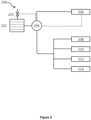
- Figure 2 provides an illustration of another embodiment of a fuel cell power management system 200.
- the system 200 of Figure 2 includes: a fuel cell stack 202 with a gas supply valve 203, a controller 204, data server racks 206 having a non-discretional load requirement, and a plurality of ancillary systems including a lighting system 208, an air conditioning system 210, an electric hot water storage system 212, and battery operated laptop devices 214 connected to the system.
- the controller 204 is configured to monitor at least the power output of the fuel cell stack 202 and the non-discretional load requirement of the data server rack 206, and to control the supply of power to the data server rack 206 to ensure that the load required by the data server rack 206 is met. On this basis, the controller may calculate a discretional load (e.g. the power drawn by the ancillary systems) being the difference between the total power supplied by the fuel cell stack 202 and the non-discretional power. The controller 204 is configured to treat this discretional load as a buffer that can be drawn upon in the event of a transient increase in the non-discretional load requirements of the data server rack 206.
- a discretional load e.g. the power drawn by the ancillary systems
- the controller 204 is configured to divert power from this buffer to ensure that the non-discretional load requirements of the data server rack 206 are met.
- the controller 206 diverts additional power to one or more of the ancillary systems 208, 210, 212, 214. If the transient change in load is sustained, the controller 204 may adjust fuel supply valve 203 and/or a steam or air supply valve (not shown) to increase or decrease the power generated by the fuel cell stack 202 as appropriate.
Landscapes
- Engineering & Computer Science (AREA)
- Theoretical Computer Science (AREA)
- General Engineering & Computer Science (AREA)
- Physics & Mathematics (AREA)
- General Physics & Mathematics (AREA)
- Electrochemistry (AREA)
- Life Sciences & Earth Sciences (AREA)
- Manufacturing & Machinery (AREA)
- Sustainable Development (AREA)
- Sustainable Energy (AREA)
- Chemical & Material Sciences (AREA)
- Chemical Kinetics & Catalysis (AREA)
- General Chemical & Material Sciences (AREA)
- Power Engineering (AREA)
- Human Computer Interaction (AREA)
- Computing Systems (AREA)
- Computer Hardware Design (AREA)
- Health & Medical Sciences (AREA)
- Artificial Intelligence (AREA)
- Computer Vision & Pattern Recognition (AREA)
- Evolutionary Computation (AREA)
- Medical Informatics (AREA)
- Software Systems (AREA)
- Automation & Control Theory (AREA)
- Fuel Cell (AREA)
- Supply And Distribution Of Alternating Current (AREA)
Claims (15)
- Ein Verfahren zum Verwalten der Leistungsanforderungen einer durch Brennstoffzellen mit Leistung versorgten Einrichtung, wobei die Einrichtung Folgendes umfasst:ein Hauptsystem (106, 206), das eine nicht wahlfreie Lastanforderung aufweist, wobei die nicht wahlfreie Lastanforderung elektrische Lasten umfasst, die für das Funktionieren des Hauptsystems (106, 206) erforderlich sind; undein oder mehrere Nebenlastverbrauchssysteme (108, 208), die eine Nennlast aufweisen, wobei das eine oder die mehreren Nebenlastverbrauchssysteme (108, 208) von dem Hauptsystem (106, 206) unabhängig sind, wobei die Nennlast elektrische Lasten umfasst, die mit einer Funktion des einen oder der mehreren Nebenlastverbrauchssysteme assoziiert sind;mindestens eine Brennstoffzelle (102, 202), um dem Hauptsystem (106, 206) Leistung bereitzustellen, um der nicht wahlfreien Lastanforderung zu entsprechen, und dem einen oder den mehreren Nebensystemen (108, 208) Leistung bereitzustellen; undein Steuersystem (104, 204), das konfiguriert ist, um die nicht wahlfreie Lastanforderung zu überwachen und die Leistungszufuhr zu dem Hauptsystem (106, 206) und dem einen oder den mehreren Nebenlastverbrauchssystemen (108, 208) zu steuern;wobei das Verfahren dadurch gekennzeichnet ist, dass es Folgendes umfasst:als Reaktion auf das Detektieren einer vorübergehenden Zunahme der nicht wahlfreien Lastanforderung:Verringern der dem einen oder den mehreren Nebenlastverbrauchssystemen (108, 208) zugeführten Leistung weg von der Nennlast, um der vorübergehenden Zunahme der nicht wahlfreien Lastanforderung zu entsprechen; undErhöhen der dem Hauptsystem (106, 206) zugeführten Leistung, um der vorübergehenden Zunahme der nicht wahlfreien Lastanforderung zu entsprechen; undals Reaktion auf das Detektieren einer vorübergehenden Abnahme der nicht wahlfreien Lastanforderung:Erhöhen der dem einen oder den mehreren Nebenlastverbrauchssystemen (108, 208) zugeführten Leistung weg von der Nennlast, um der vorübergehenden Abnahme der nicht wahlfreien Lastanforderung zu entsprechen; undVerringern der dem Hauptsystem (106, 206) zugeführten Leistung, um der vorübergehenden Abnahme der nicht wahlfreien Lastanforderung zu entsprechen.
- Verfahren gemäß Anspruch 1, wobei die Einrichtung ein Rechenzentrum ist und das Hauptsystem (106, 206) ein Server-Rack ist, das einen oder mehrere Server umfasst.
- Verfahren gemäß Anspruch 2, wobei die nicht wahlfreie Last des Server-Racks mindestens die Last umfasst, die für die Rechenleistung der Server und die interne Kühlung der Server und/oder des Server-Racks erforderlich ist.
- Verfahren gemäß einem der vorhergehenden Ansprüche, wobei, wenn die vorübergehende Zunahme oder Abnahme der nicht wahlfreien Lastanforderung aufrechterhalten wird, das Verfahren ferner das anschließende Ändern der Leistungsabgabe der mindestens einen Brennstoffzelle (102, 202) umfasst, um der vorübergehenden Zunahme oder Abnahme der nicht wahlfreien Lastanforderung zu entsprechen, während dem einen oder den mehreren Nebenlastverbrauchssystemen (108, 208) Leistung auf der Höhe der Nennlast bereitgestellt wird.
- Verfahren gemäß einem der vorhergehenden Ansprüche, wobei die Einrichtung eine Vielzahl von Nebenlastverbrauchssystemen (108-114, 204-214) umfasst, wobei jedes Nebenlastverbrauchssystem (108-114, 204-214) einen jeweiligen Nennlast-Sollwert und jeweiligen Betriebslastbereich, der den Nennlast-Sollwert umfasst, aufweist; wobei der Schritt des Anpassens der dem einen oder den mehreren der Vielzahl von Nebenlastverbrauchssystemen (108-114, 204-214) zugeführten Leistung Folgendes umfasst:Auswählen eines oder mehrerer Nebenlastverbrauchssysteme (108-114, 204-214);Anpassen der jedem der ausgewählten Nebenlastverbrauchssysteme (108-114, 204-214) zugeführten Leistung von dem jeweiligen Nennsollwert auf einen anderen Lastwert innerhalb des jeweiligen Betriebslastbereichs; undBereitstellen von Leistung für das eine oder die mehreren Nebenlastverbrauchssysteme, um der aktualisierten Nennlast zu entsprechen.
- Verfahren gemäß Anspruch 5, wobei das Steuersystem konfiguriert ist, um jedem Nebenlastverbrauchssystem (108-114, 204-214) in der Vielzahl von Lastverbrauchssystemen einen Rang zuzuweisen, wobei der Schritt des Auswählens eines oder mehrerer Nebenlastverbrauchssysteme das Auswählen des einen oder der mehreren Nebenlastverbrauchssysteme auf der Basis des zugewiesenen Rangs umfasst.
- Verfahren gemäß Anspruch 6, wobei das Steuersystem konfiguriert ist, um jedem Nebenlastverbrauchssystem (108-114, 204-214) auf der Basis eines mit jedem Lastverbrauchssystem assoziierten Wirkungszeitparameters einen Rang zuzuweisen.
- Verfahren gemäß Anspruch 7, wobei das Steuersystem konfiguriert ist, um jedem Nebenlastverbrauchssystem (108-114, 204-214) in der Reihenfolge von einem höchsten assoziierten Wirkungszeitparameter zu einem niedrigsten assoziierten Wirkungszeitparameter einen Rang zuzuweisen.
- Verfahren gemäß einem der vorhergehenden Ansprüche, wobei:die Leistung, um der nicht wahlfreien Lastanforderung zu entsprechen, nicht durch eines oder mehrere der Folgenden bereitgestellt wird: eine Batterie und/oder einen Kondensator und/oder einen Superkondensator und/oder ein kommunales Stromversorgungsnetz; und/oderdie Leistung für das eine oder die mehreren Nebenlastverbrauchssysteme (108-114, 204-214) nicht durch eines oder mehrere der Folgenden bereitgestellt wird: eine Batterie, einen Kondensator, einen Superkondensator, ein kommunales Stromversorgungsnetz.
- Ein Brennstoffzellen-Stromversorgungssystem (100, 200) für eine Einrichtung, wobei das Brennstoffzellen-Stromversorgungssystem (100, 200) Folgendes umfasst:mindestens eine Brennstoffzelle (102, 202), die Leistung für Folgendes bereitstellt:ein Hauptsystem (106, 206) einer Einrichtung, um einer nicht wahlfreien Lastanforderung des Hauptsystems (106, 206) zu entsprechen, wobei die nicht wahlfreie Lastanforderung elektrische Lasten umfasst, die für das Funktionieren des Hauptsystems (106, 206) erforderlich sind; undein oder mehrere Nebenlastverbrauchssysteme (108, 208) der Einrichtung, die eine Nennlast aufweisen, wobei das eine oder die mehreren Nebenlastverbrauchssysteme (108, 208) von dem Hauptsystem (106, 206) unabhängig sind, wobei die Nennlast elektrische Lasten umfasst, die mit einer Funktion des einen oder der mehreren Nebenlastverbrauchssysteme (108, 208) assoziiert sind; undein Steuersystem (104, 204), das konfiguriert ist, um die nicht wahlfreie Lastanforderung des Hauptsystems (106, 206) zu überwachen und die Leistungszufuhr zu dem Hauptsystem (106, 206) und dem einen oder den mehreren Nebenlastverbrauchssystemen (108, 208) zu steuern;wobei das Steuersystem (104, 204) dadurch gekennzeichnet ist, dass es für Folgendes konfiguriert ist:als Reaktion auf das Detektieren einer vorübergehenden Zunahme der nicht wahlfreien Lastanforderung:Verringern der dem einen oder den mehreren Nebenlastverbrauchssystemen (108, 208) zugeführten Leistung weg von der Nennlast, um der vorübergehenden Zunahme der nicht wahlfreien Lastanforderung zu entsprechen; undErhöhen der dem Hauptsystem (106, 206) zugeführten Leistung, um der vorübergehenden Zunahme der nicht wahlfreien Lastanforderung zu entsprechen; undals Reaktion auf das Detektieren einer vorübergehenden Abnahme der nicht wahlfreien Lastanforderung:Erhöhen der dem einen oder den mehreren Nebenlastverbrauchssystemen (108, 208) zugeführten Leistung weg von der Nennlast, um der vorübergehenden Abnahme der nicht wahlfreien Lastanforderung zu entsprechen; undVerringern der dem Hauptsystem (106, 206) zugeführten Leistung, um der vorübergehenden Abnahme der nicht wahlfreien Lastanforderung zu entsprechen.
- Brennstoffzellen-Stromversorgungssystem gemäß Anspruch 10, wobei die Einrichtung ein Rechenzentrum ist und das Hauptsystem (106, 206) ein Server-Rack ist.
- Brennstoffzellen-Stromversorgungssystem gemäß Anspruch 10 oder Anspruch 11, wobei das Steuersystem (104, 204) ferner für Folgendes konfiguriert ist:Auswählen eines oder mehrerer Nebenlastverbrauchssysteme aus einer Vielzahl von Nebenlastverbrauchssystemen (108-114, 204-214), wobei jedes Nebenlastverbrauchssystem einen jeweiligen Nennlast-Sollwert und jeweiligen Betriebslastbereich, der den Nennlast-Sollwert umfasst, aufweist;Anpassen der jedem der ausgewählten Nebenlastverbrauchssysteme zugeführten Leistung von dem jeweiligen Nennlast-Sollwert auf einen anderen Lastwert innerhalb des jeweiligen Betriebslastbereichs; undAbleiten von Leistung von oder Bereitstellen von Leistung für den einen oder die mehreren Nebenlastverbrauchsdienste, um dem Lastwert zu entsprechen.
- Brennstoffzellen-Stromversorgungssystem gemäß Anspruch 12, wobei, wenn die vorübergehende Zunahme oder Abnahme der nicht wahlfreien Lastanforderung aufrechterhalten wird, das Steuersystem (104, 204) ferner konfiguriert ist, um die Leistungsabgabe der mindestens einen Brennstoffzelle (102, 202) zu ändern, um der vorübergehenden Zunahme oder Abnahme der nicht wahlfreien Lastanforderung zu entsprechen, während dem einen oder den mehreren Nebenlastverbrauchssystemen (108-114, 204-214) Leistung auf dem Nennlast-Sollwert bereitgestellt wird.
- Brennstoffzellen-Stromversorgungssystem gemäß Anspruch 12 oder Anspruch 13, wobei das Steuersystem (104, 204) ferner konfiguriert ist, um jedem Nebenlastverbrauchssystem (108-114, 204-214) in der Vielzahl von Lastverbrauchssystemen einen Rang zuzuweisen, wobei das Steuersystem (104, 204) konfiguriert ist, um ein oder mehrere Nebenlastverbrauchssysteme (108-114, 204-214) auf der Basis des zugewiesenen Rangs auszuwählen.
- Eine Einrichtung, die das Brennstoffzellen-Stromversorgungssystem (100, 200) gemäß Anspruch 10 umfasst.
Applications Claiming Priority (2)
| Application Number | Priority Date | Filing Date | Title |
|---|---|---|---|
| AU2019901138A AU2019901138A0 (en) | 2019-04-03 | Energy management system for fuel cells | |
| PCT/AU2020/050330 WO2020198800A1 (en) | 2019-04-03 | 2020-04-03 | Energy management systems for fuel cells |
Publications (4)
| Publication Number | Publication Date |
|---|---|
| EP3949065A1 EP3949065A1 (de) | 2022-02-09 |
| EP3949065A4 EP3949065A4 (de) | 2023-03-15 |
| EP3949065B1 true EP3949065B1 (de) | 2025-06-04 |
| EP3949065C0 EP3949065C0 (de) | 2025-06-04 |
Family
ID=72664331
Family Applications (1)
| Application Number | Title | Priority Date | Filing Date |
|---|---|---|---|
| EP20784215.4A Active EP3949065B1 (de) | 2019-04-03 | 2020-04-03 | Energieverwaltungssysteme für brennstoffzellen |
Country Status (6)
| Country | Link |
|---|---|
| US (1) | US11784333B2 (de) |
| EP (1) | EP3949065B1 (de) |
| KR (1) | KR102564903B1 (de) |
| AU (1) | AU2020255673B2 (de) |
| SA (1) | SA521430429B1 (de) |
| WO (1) | WO2020198800A1 (de) |
Families Citing this family (1)
| Publication number | Priority date | Publication date | Assignee | Title |
|---|---|---|---|---|
| KR102822851B1 (ko) * | 2023-11-20 | 2025-06-19 | 주식회사 호그린에어 | 수소 연료전지 모니터링 시스템 |
Family Cites Families (18)
| Publication number | Priority date | Publication date | Assignee | Title |
|---|---|---|---|---|
| US6680547B1 (en) * | 2002-08-01 | 2004-01-20 | Innovations Electrical, Lc | Power sharing system including rechargeable power source |
| US7447920B2 (en) * | 2004-08-31 | 2008-11-04 | Hewlett-Packard Development Company, L.P. | Workload placement based on thermal considerations |
| US20060046107A1 (en) * | 2004-09-01 | 2006-03-02 | Caterpillar Inc. | System for fuel cell power plant load following and power regulation |
| US7514815B2 (en) * | 2004-09-28 | 2009-04-07 | American Power Conversion Corporation | System and method for allocating power to loads |
| CA2640756A1 (en) * | 2006-02-06 | 2007-08-16 | Optimal Innovations, Inc. | Management of high-availability power infrastructures |
| EP2098942A1 (de) | 2008-03-03 | 2009-09-09 | British Telecmmunications public limited campany | Computersystem und Betriebsverfahren dafür |
| US8782234B2 (en) * | 2008-05-05 | 2014-07-15 | Siemens Industry, Inc. | Arrangement for managing data center operations to increase cooling efficiency |
| GB0818174D0 (en) * | 2008-10-03 | 2008-11-12 | Leaneco Aps | Emergency power supply apparatus |
| US20100257529A1 (en) * | 2009-04-06 | 2010-10-07 | Christopher Wilkerson | Efficient systems and methods for consuming and providing power |
| US10203735B2 (en) * | 2012-03-21 | 2019-02-12 | Bloom Energy Corporation | Systems and methods for providing fuel cell power to a data center |
| US9711988B2 (en) * | 2012-06-01 | 2017-07-18 | Panasonic Intellectual Property Management Co., Ltd. | Fuel cell system, method for controlling fuel cell system, and storage battery system |
| US9141923B2 (en) * | 2012-09-25 | 2015-09-22 | Bloom Energy Corporation | Optimizing contractual management of the total output of a fleet of fuel cells |
| WO2014062657A1 (en) * | 2012-10-16 | 2014-04-24 | Bloom Energy Corporation | Energy load management system |
| US9563483B2 (en) * | 2012-12-19 | 2017-02-07 | Microsoft Technology Licensing, Llc | Server rack fuel cell |
| JP6770581B2 (ja) | 2016-03-02 | 2020-10-14 | フュエルセル エナジー, インコーポレイテッドFuelcell Energy, Inc. | 直流(dc)負荷平準化器 |
| US10585468B2 (en) | 2016-08-18 | 2020-03-10 | Virtual Power Systems, Inc. | Datacenter power management using dynamic redundancy |
| US11072321B2 (en) * | 2018-12-31 | 2021-07-27 | Thermo King Corporation | Systems and methods for smart load shedding of a transport vehicle while in transit |
| US11287863B2 (en) | 2019-02-06 | 2022-03-29 | Google Llc | Fuel cell power management |
-
2020
- 2020-04-03 AU AU2020255673A patent/AU2020255673B2/en active Active
- 2020-04-03 KR KR1020217035245A patent/KR102564903B1/ko active Active
- 2020-04-03 WO PCT/AU2020/050330 patent/WO2020198800A1/en not_active Ceased
- 2020-04-03 EP EP20784215.4A patent/EP3949065B1/de active Active
- 2020-04-03 US US17/598,658 patent/US11784333B2/en active Active
-
2021
- 2021-09-28 SA SA521430429A patent/SA521430429B1/ar unknown
Also Published As
| Publication number | Publication date |
|---|---|
| KR102564903B1 (ko) | 2023-08-08 |
| AU2020255673B2 (en) | 2021-12-09 |
| US11784333B2 (en) | 2023-10-10 |
| EP3949065C0 (de) | 2025-06-04 |
| KR20210141735A (ko) | 2021-11-23 |
| WO2020198800A1 (en) | 2020-10-08 |
| AU2020255673A1 (en) | 2021-08-12 |
| US20220181657A1 (en) | 2022-06-09 |
| EP3949065A4 (de) | 2023-03-15 |
| SA521430429B1 (ar) | 2023-12-18 |
| EP3949065A1 (de) | 2022-02-09 |
Similar Documents
| Publication | Publication Date | Title |
|---|---|---|
| KR102572526B1 (ko) | 에너지 스토리지 배터리 구획을 위한 온도 제어 방법 및 에너지 스토리지 시스템을 위한 방전 제어 방법 및 에너지 스토리지 애플리케이션 시스템 | |
| US8035250B2 (en) | System and method for load sharing in multi-module power supply systems | |
| CN112334857B (zh) | 燃料单体电力管理 | |
| EP2936271B1 (de) | Brennstoffzelle für serverrack | |
| AU2013101461A4 (en) | Grid stability control system and method | |
| US20150123475A1 (en) | Control of Operating Equipment by Influencing a Grid Voltage | |
| CN119543400A (zh) | 一种模块化电源的电力分配系统及方法 | |
| CN114976376A (zh) | 锂离子电池系统的热管理控制的方法和系统 | |
| EP3949065B1 (de) | Energieverwaltungssysteme für brennstoffzellen | |
| GB2628892A (en) | Systems and methods for paralleling multiple power sources | |
| US20250239862A1 (en) | Systems and methods for paralleling multiple power sources | |
| JP2012151977A (ja) | 負荷平準化システム | |
| US20210234210A1 (en) | Control apparatus of storage battery and control method for storage battery | |
| US20260045529A1 (en) | Fleet of fuel cell-based generation systems and a control method thereof | |
| US20250385526A1 (en) | Control system for protecting multi-unit fuel cell system | |
| WO2026032516A1 (en) | A fleet of fuel cell-based generation systems and a control method thereof | |
| Dharani et al. | Control of Supercapacitor-Based Energy Storage System of DC Microgrid Using PI Controller | |
| CN119787555A (zh) | 一种动力电池梯次利用的智能医疗供电管理系统 | |
| CN120546253A (zh) | 储能系统、储能系统的供电方法与用电设备 | |
| CN120999803A (zh) | 制氢系统的控制方法、装置、制氢系统、介质及程序产品 | |
| CN116914828A (zh) | 一种自调节负载及燃料电池发电系统 |
Legal Events
| Date | Code | Title | Description |
|---|---|---|---|
| STAA | Information on the status of an ep patent application or granted ep patent |
Free format text: STATUS: THE INTERNATIONAL PUBLICATION HAS BEEN MADE |
|
| PUAI | Public reference made under article 153(3) epc to a published international application that has entered the european phase |
Free format text: ORIGINAL CODE: 0009012 |
|
| STAA | Information on the status of an ep patent application or granted ep patent |
Free format text: STATUS: REQUEST FOR EXAMINATION WAS MADE |
|
| 17P | Request for examination filed |
Effective date: 20211020 |
|
| AK | Designated contracting states |
Kind code of ref document: A1 Designated state(s): AL AT BE BG CH CY CZ DE DK EE ES FI FR GB GR HR HU IE IS IT LI LT LU LV MC MK MT NL NO PL PT RO RS SE SI SK SM TR |
|
| DAV | Request for validation of the european patent (deleted) | ||
| DAX | Request for extension of the european patent (deleted) | ||
| A4 | Supplementary search report drawn up and despatched |
Effective date: 20230210 |
|
| RIC1 | Information provided on ipc code assigned before grant |
Ipc: G06F 1/18 20060101ALI20230206BHEP Ipc: G06F 1/26 20060101ALI20230206BHEP Ipc: H02J 1/14 20060101ALI20230206BHEP Ipc: H02J 3/14 20060101AFI20230206BHEP |
|
| STAA | Information on the status of an ep patent application or granted ep patent |
Free format text: STATUS: EXAMINATION IS IN PROGRESS |
|
| 17Q | First examination report despatched |
Effective date: 20231031 |
|
| GRAP | Despatch of communication of intention to grant a patent |
Free format text: ORIGINAL CODE: EPIDOSNIGR1 |
|
| STAA | Information on the status of an ep patent application or granted ep patent |
Free format text: STATUS: GRANT OF PATENT IS INTENDED |
|
| INTG | Intention to grant announced |
Effective date: 20241118 |
|
| GRAS | Grant fee paid |
Free format text: ORIGINAL CODE: EPIDOSNIGR3 |
|
| GRAA | (expected) grant |
Free format text: ORIGINAL CODE: 0009210 |
|
| STAA | Information on the status of an ep patent application or granted ep patent |
Free format text: STATUS: THE PATENT HAS BEEN GRANTED |
|
| AK | Designated contracting states |
Kind code of ref document: B1 Designated state(s): AL AT BE BG CH CY CZ DE DK EE ES FI FR GB GR HR HU IE IS IT LI LT LU LV MC MK MT NL NO PL PT RO RS SE SI SK SM TR |
|
| REG | Reference to a national code |
Ref country code: GB Ref legal event code: FG4D |
|
| REG | Reference to a national code |
Ref country code: CH Ref legal event code: EP |
|
| REG | Reference to a national code |
Ref country code: DE Ref legal event code: R096 Ref document number: 602020052332 Country of ref document: DE |
|
| REG | Reference to a national code |
Ref country code: IE Ref legal event code: FG4D |
|
| U01 | Request for unitary effect filed |
Effective date: 20250703 |
|
| RAP2 | Party data changed (patent owner data changed or rights of a patent transferred) |
Owner name: SOLYDERA SPA |
|
| U07 | Unitary effect registered |
Designated state(s): AT BE BG DE DK EE FI FR IT LT LU LV MT NL PT RO SE SI Effective date: 20250709 |
|
| PG25 | Lapsed in a contracting state [announced via postgrant information from national office to epo] |
Ref country code: ES Free format text: LAPSE BECAUSE OF FAILURE TO SUBMIT A TRANSLATION OF THE DESCRIPTION OR TO PAY THE FEE WITHIN THE PRESCRIBED TIME-LIMIT Effective date: 20250604 |
|
| PG25 | Lapsed in a contracting state [announced via postgrant information from national office to epo] |
Ref country code: GR Free format text: LAPSE BECAUSE OF FAILURE TO SUBMIT A TRANSLATION OF THE DESCRIPTION OR TO PAY THE FEE WITHIN THE PRESCRIBED TIME-LIMIT Effective date: 20250905 Ref country code: NO Free format text: LAPSE BECAUSE OF FAILURE TO SUBMIT A TRANSLATION OF THE DESCRIPTION OR TO PAY THE FEE WITHIN THE PRESCRIBED TIME-LIMIT Effective date: 20250904 |
|
| PG25 | Lapsed in a contracting state [announced via postgrant information from national office to epo] |
Ref country code: PL Free format text: LAPSE BECAUSE OF FAILURE TO SUBMIT A TRANSLATION OF THE DESCRIPTION OR TO PAY THE FEE WITHIN THE PRESCRIBED TIME-LIMIT Effective date: 20250604 |
|
| PG25 | Lapsed in a contracting state [announced via postgrant information from national office to epo] |
Ref country code: HR Free format text: LAPSE BECAUSE OF FAILURE TO SUBMIT A TRANSLATION OF THE DESCRIPTION OR TO PAY THE FEE WITHIN THE PRESCRIBED TIME-LIMIT Effective date: 20250604 |
|
| PG25 | Lapsed in a contracting state [announced via postgrant information from national office to epo] |
Ref country code: RS Free format text: LAPSE BECAUSE OF FAILURE TO SUBMIT A TRANSLATION OF THE DESCRIPTION OR TO PAY THE FEE WITHIN THE PRESCRIBED TIME-LIMIT Effective date: 20250904 |
|
| PG25 | Lapsed in a contracting state [announced via postgrant information from national office to epo] |
Ref country code: IS Free format text: LAPSE BECAUSE OF FAILURE TO SUBMIT A TRANSLATION OF THE DESCRIPTION OR TO PAY THE FEE WITHIN THE PRESCRIBED TIME-LIMIT Effective date: 20251004 |
|
| PG25 | Lapsed in a contracting state [announced via postgrant information from national office to epo] |
Ref country code: SM Free format text: LAPSE BECAUSE OF FAILURE TO SUBMIT A TRANSLATION OF THE DESCRIPTION OR TO PAY THE FEE WITHIN THE PRESCRIBED TIME-LIMIT Effective date: 20250604 |
|
| PG25 | Lapsed in a contracting state [announced via postgrant information from national office to epo] |
Ref country code: CZ Free format text: LAPSE BECAUSE OF FAILURE TO SUBMIT A TRANSLATION OF THE DESCRIPTION OR TO PAY THE FEE WITHIN THE PRESCRIBED TIME-LIMIT Effective date: 20250604 |
|
| PG25 | Lapsed in a contracting state [announced via postgrant information from national office to epo] |
Ref country code: SK Free format text: LAPSE BECAUSE OF FAILURE TO SUBMIT A TRANSLATION OF THE DESCRIPTION OR TO PAY THE FEE WITHIN THE PRESCRIBED TIME-LIMIT Effective date: 20250604 |