EP3948099B1 - Dämpfereinstellungsanordnung - Google Patents
Dämpfereinstellungsanordnung Download PDFInfo
- Publication number
- EP3948099B1 EP3948099B1 EP20784592.6A EP20784592A EP3948099B1 EP 3948099 B1 EP3948099 B1 EP 3948099B1 EP 20784592 A EP20784592 A EP 20784592A EP 3948099 B1 EP3948099 B1 EP 3948099B1
- Authority
- EP
- European Patent Office
- Prior art keywords
- bulges
- damper
- adjusting arrangement
- damper adjusting
- extractor
- Prior art date
- Legal status (The legal status is an assumption and is not a legal conclusion. Google has not performed a legal analysis and makes no representation as to the accuracy of the status listed.)
- Active
Links
Images

Classifications
-
- B—PERFORMING OPERATIONS; TRANSPORTING
- B08—CLEANING
- B08B—CLEANING IN GENERAL; PREVENTION OF FOULING IN GENERAL
- B08B15/00—Preventing escape of dirt or fumes from the area where they are produced; Collecting or removing dirt or fumes from that area
- B08B15/04—Preventing escape of dirt or fumes from the area where they are produced; Collecting or removing dirt or fumes from that area from a small area, e.g. a tool
-
- F—MECHANICAL ENGINEERING; LIGHTING; HEATING; WEAPONS; BLASTING
- F16—ENGINEERING ELEMENTS AND UNITS; GENERAL MEASURES FOR PRODUCING AND MAINTAINING EFFECTIVE FUNCTIONING OF MACHINES OR INSTALLATIONS; THERMAL INSULATION IN GENERAL
- F16K—VALVES; TAPS; COCKS; ACTUATING-FLOATS; DEVICES FOR VENTING OR AERATING
- F16K1/00—Lift valves or globe valves, i.e. cut-off apparatus with closure members having at least a component of their opening and closing motion perpendicular to the closing faces
- F16K1/16—Lift valves or globe valves, i.e. cut-off apparatus with closure members having at least a component of their opening and closing motion perpendicular to the closing faces with pivoted closure-members
- F16K1/18—Lift valves or globe valves, i.e. cut-off apparatus with closure members having at least a component of their opening and closing motion perpendicular to the closing faces with pivoted closure-members with pivoted discs or flaps
- F16K1/22—Lift valves or globe valves, i.e. cut-off apparatus with closure members having at least a component of their opening and closing motion perpendicular to the closing faces with pivoted closure-members with pivoted discs or flaps with axis of rotation crossing the valve member, e.g. butterfly valves
- F16K1/221—Lift valves or globe valves, i.e. cut-off apparatus with closure members having at least a component of their opening and closing motion perpendicular to the closing faces with pivoted closure-members with pivoted discs or flaps with axis of rotation crossing the valve member, e.g. butterfly valves specially adapted operating means therefor
-
- B—PERFORMING OPERATIONS; TRANSPORTING
- B08—CLEANING
- B08B—CLEANING IN GENERAL; PREVENTION OF FOULING IN GENERAL
- B08B15/00—Preventing escape of dirt or fumes from the area where they are produced; Collecting or removing dirt or fumes from that area
-
- F—MECHANICAL ENGINEERING; LIGHTING; HEATING; WEAPONS; BLASTING
- F16—ENGINEERING ELEMENTS AND UNITS; GENERAL MEASURES FOR PRODUCING AND MAINTAINING EFFECTIVE FUNCTIONING OF MACHINES OR INSTALLATIONS; THERMAL INSULATION IN GENERAL
- F16K—VALVES; TAPS; COCKS; ACTUATING-FLOATS; DEVICES FOR VENTING OR AERATING
- F16K1/00—Lift valves or globe valves, i.e. cut-off apparatus with closure members having at least a component of their opening and closing motion perpendicular to the closing faces
- F16K1/16—Lift valves or globe valves, i.e. cut-off apparatus with closure members having at least a component of their opening and closing motion perpendicular to the closing faces with pivoted closure-members
- F16K1/18—Lift valves or globe valves, i.e. cut-off apparatus with closure members having at least a component of their opening and closing motion perpendicular to the closing faces with pivoted closure-members with pivoted discs or flaps
- F16K1/22—Lift valves or globe valves, i.e. cut-off apparatus with closure members having at least a component of their opening and closing motion perpendicular to the closing faces with pivoted closure-members with pivoted discs or flaps with axis of rotation crossing the valve member, e.g. butterfly valves
-
- F—MECHANICAL ENGINEERING; LIGHTING; HEATING; WEAPONS; BLASTING
- F16—ENGINEERING ELEMENTS AND UNITS; GENERAL MEASURES FOR PRODUCING AND MAINTAINING EFFECTIVE FUNCTIONING OF MACHINES OR INSTALLATIONS; THERMAL INSULATION IN GENERAL
- F16K—VALVES; TAPS; COCKS; ACTUATING-FLOATS; DEVICES FOR VENTING OR AERATING
- F16K1/00—Lift valves or globe valves, i.e. cut-off apparatus with closure members having at least a component of their opening and closing motion perpendicular to the closing faces
- F16K1/32—Details
- F16K1/52—Means for additional adjustment of the rate of flow
-
- F—MECHANICAL ENGINEERING; LIGHTING; HEATING; WEAPONS; BLASTING
- F16—ENGINEERING ELEMENTS AND UNITS; GENERAL MEASURES FOR PRODUCING AND MAINTAINING EFFECTIVE FUNCTIONING OF MACHINES OR INSTALLATIONS; THERMAL INSULATION IN GENERAL
- F16K—VALVES; TAPS; COCKS; ACTUATING-FLOATS; DEVICES FOR VENTING OR AERATING
- F16K31/00—Actuating devices; Operating means; Releasing devices
- F16K31/44—Mechanical actuating means
- F16K31/53—Mechanical actuating means with toothed gearing
- F16K31/535—Mechanical actuating means with toothed gearing for rotating valves
-
- F—MECHANICAL ENGINEERING; LIGHTING; HEATING; WEAPONS; BLASTING
- F16—ENGINEERING ELEMENTS AND UNITS; GENERAL MEASURES FOR PRODUCING AND MAINTAINING EFFECTIVE FUNCTIONING OF MACHINES OR INSTALLATIONS; THERMAL INSULATION IN GENERAL
- F16K—VALVES; TAPS; COCKS; ACTUATING-FLOATS; DEVICES FOR VENTING OR AERATING
- F16K31/00—Actuating devices; Operating means; Releasing devices
- F16K31/44—Mechanical actuating means
- F16K31/60—Handles
-
- F—MECHANICAL ENGINEERING; LIGHTING; HEATING; WEAPONS; BLASTING
- F24—HEATING; RANGES; VENTILATING
- F24F—AIR-CONDITIONING; AIR-HUMIDIFICATION; VENTILATION; USE OF AIR CURRENTS FOR SCREENING
- F24F13/00—Details common to, or for air-conditioning, air-humidification, ventilation or use of air currents for screening
- F24F13/08—Air-flow control members, e.g. louvres, grilles, flaps or guide plates
- F24F13/10—Air-flow control members, e.g. louvres, grilles, flaps or guide plates movable, e.g. dampers
- F24F13/14—Air-flow control members, e.g. louvres, grilles, flaps or guide plates movable, e.g. dampers built up of tilting members, e.g. louvre
- F24F13/1426—Air-flow control members, e.g. louvres, grilles, flaps or guide plates movable, e.g. dampers built up of tilting members, e.g. louvre characterised by actuating means
- F24F2013/146—Air-flow control members, e.g. louvres, grilles, flaps or guide plates movable, e.g. dampers built up of tilting members, e.g. louvre characterised by actuating means with springs
-
- F—MECHANICAL ENGINEERING; LIGHTING; HEATING; WEAPONS; BLASTING
- F24—HEATING; RANGES; VENTILATING
- F24F—AIR-CONDITIONING; AIR-HUMIDIFICATION; VENTILATION; USE OF AIR CURRENTS FOR SCREENING
- F24F13/00—Details common to, or for air-conditioning, air-humidification, ventilation or use of air currents for screening
- F24F13/08—Air-flow control members, e.g. louvres, grilles, flaps or guide plates
- F24F13/10—Air-flow control members, e.g. louvres, grilles, flaps or guide plates movable, e.g. dampers
- F24F13/14—Air-flow control members, e.g. louvres, grilles, flaps or guide plates movable, e.g. dampers built up of tilting members, e.g. louvre
- F24F13/1426—Air-flow control members, e.g. louvres, grilles, flaps or guide plates movable, e.g. dampers built up of tilting members, e.g. louvre characterised by actuating means
- F24F2013/1473—Air-flow control members, e.g. louvres, grilles, flaps or guide plates movable, e.g. dampers built up of tilting members, e.g. louvre characterised by actuating means with cams or levers
Definitions
- the present invention relates to a damper adjusting arrangement configured for regulating the flow of a gaseous fluid within a channel of an extractor tubing.
- the present invention may concern the industry manufacturing ventilation arrangements designed for capturing gases or may concern the industry using such damper adjusting arrangements.
- the present invention may concern a damper adjusting arrangement that is configured to be mounted to a wide range of extraction apparatuses configured to capture e.g. welding fumes and dust at the source or work site.
- the captured gas may be smoke, welding fume, dusts, vapours or other gaseous fluid.
- the present invention especially may concern the fume extractor manufacturing industry producing damper adjusting arrangements configured for high suction and high flow extraction performances.
- the present invention especially may concern the industry making use of such damper adjusting arrangements.
- the invention relates to a damper adjusting arrangement, wherein the dampening of the flow of gaseous fluid through the extractor tubing is possible to adjust in a rigid way and in a controlled manner.
- the need to adjust the flow of gaseous fluids, guided by the channel of the extractor tubing of the ventilation arrangements, may be present. If only a small amount of gaseous fluid needs to be collected by the arrangement, it may be ineffective to extract the gaseous fluid at full effect.
- the disc shaped element is preferably coupled to a rotary shaft reachable exterior the extractor tubing directly or indirectly via a handle. The operator rotates the handle for adjusting the angle of the disc shaped element relative the centre line of the channel of the extractor tubing.
- the shaft preferably extends through the wall of the extractor tubing on opposite sides to ensure a secure mounting of the shaft to the extractor tubing.
- Adjustable dampers may be subjected to heat, oil, high under pressure, dirt, etc.
- Chinese design registration ZL 201630495253.0 discloses an adjustable damper arrangement comprising a disc shaped element pivotable arranged in a channel of an extractor tubing and coupled to a handle arranged exterior the extractor tubing.
- the handle is provided with a plurality of bulges protruding in axially direction and arranged in a plane extending transversal to the axis of the channel in accordance with a certain pattern.
- the pattern engages a corresponding pattern of a base portion for forming a friction joint configured to keep the disc shaped element in the adjusted position relative the centre line of the extractor tubing.
- CN 206247583U discloses a damper according to the preamble of claim 1.
- An object is to provide a damper adjusting arrangement, which comprises a rotary control means configured to regulate the flow of gaseous fluid in the channel of the extractor tubing in a reliable way.
- An object is to provide a damper adjusting arrangement, which is robust, user friendly, cost-effective to manufacture and which may exhibit long-life and long-term mechanical performance.
- a further object is to provide a damper adjusting arrangement, which is able to regulate the dampening effect in discrete steps.
- An object is to provide a damper adjusting arrangement comprising a damper member, which may be rotated between a fully open state and a fully closed state in said channel of the extractor tubing.
- An object of the present invention is to provide a damper adjusting arrangement, which overcomes drawbacks of prior art.
- the resilient element comprising a plurality of radially and inwardly protruding first bulges.
- the first member comprises a plurality of radially and inwardly protruding first bulges.
- the second member comprises a plurality of radially and outwardly protruding second bulges.
- the plurality of radially and inwardly protruding first bulges being configured for engagement with the plurality of radially and outwardly protruding second bulges.
- the first member comprises a first leg connected to or integrally joined to a first and a second end portion of the first member.
- the first member comprises a second leg connected to or integrally joined to the first and the second end portion of the first member.
- the first end portion comprises a first through hole and/or the second end portion comprises a second through hole.
- the resilient element comprises said first and second leg.
- the first member is formed as an elongated washer-like planar tongue comprising a central open area, configured to encompass the second member, and having the first and the second leg connected to the first and to the second end portion, wherein the first and second leg each comprises a plurality of inwardly facing bulges forming a wave-shaped pattern.
- an imaginary central axis extends through the central open area and extends perpendicular to the plane of the elongated washer-like planar tongue.
- the first member comprises a plurality of radially first bulges, protruding inwardly towards an imaginary central axis, about which the damper member is pivotable.
- the first leg comprises a first flexible portion and a second flexible portion, wherein a first plurality of said first bulges are positioned between the first flexible portion and the second flexible portion and being configured to engage the second member.
- the second leg comprises a third flexible portion and a fourth flexible portion, wherein a second plurality of said first bulges are positioned between the third flexible portion and the fourth flexible portion and being configured to engage the second member.
- first and/or second and/or third and/or fourth flexible portion exhibiting various thickness and/or width.
- first and/or second and/or third and/or fourth flexible portion exhibiting a first width and a second width, wherein the first width is wider than the second width, for providing a flexibility and/or a resilience of the resilient element.
- the first member comprises steel (e.g. high-strength steel or hardened steel or other suitable composition of steel).
- the first member is entirely made of resilient material.
- the first member is formed as an elongated washer-like planar tongue with an open area and having a first and second leg connected to a first and a second end portion, wherein the first and second leg each comprises a plurality of inwardly facing bulges forming a wave-shaped pattern.
- the first member can be manufactured as a sheet metal pressed component, wherein the damper adjusting arrangement can be produced cost-effective.
- the second member is positioned between and in contact with the first and second leg.
- each first and second leg may be formed as a rod or strip and may be integrated parts of the first member.
- the first member may be of generally elongated configuration or any other appropriate configuration.
- the respective first and second leg being configured to be spring-biased against the second member.
- the second member is configured as a wheel, a ring- or disc-shaped body or other circular body configured to be able to be rotated together with the axis, when the first and second leg spring in a direction away from the second member and the plurality of first bulges ride over the engaged second bulges of the second member.
- the first bulges being formed along at least one imaginary arc.
- the imaginary arc is defined by an imaginary circle, the centre of which corresponds with a rotary axis of the second member.
- the first member of the rotary control means comprises a resilient washer or washer-like resilient member having a plurality of inwardly and in radial direction protruding bulges.
- the resilient washer or washer-like resilient member comprises high-strength steel or high-strength low-alloy steel or stainless steel.
- the plurality of inwardly and in radial direction protruding first bulges being formed along at least one imaginary circular arc defined by the radius between the perimeter and the rotary axis the second member.
- the plurality of inwardly and in radial direction protruding first bulges being formed along two opposite arranged imaginary circular arcs of the first member.
- the imaginary circular arc is formed by a well-defined sector of an imaginary circle, the centre of which corresponds with a rotary axis of the second member.
- the plurality of outwardly and radially protruding second bulges is formed around an outer periphery of the second member, wherein the plurality of bulges forms a wave-shaped pattern.
- the second member comprises a non-resilient engagement portion configured to be engaged with the first member and configured to be rotatable arranged and coupled to the damper member for providing a rotary motion thereof.
- the resilient element of the first member exhibits a higher degree of resilience than that of the second member.
- the second member comprises a plurality of outwardly and in radial direction protruding bulges, the geometry of which corresponds with the geometry of the inwardly protruding bulges of the first member.
- a handle member is coupled to the damper member via the second member, which handle member is rotary arranged exterior the extractor tubing for providing a rotary motion of the second member.
- the handle member is coupled to the damper member via a shaft comprising the second member.
- the engagement portion of second member is configured to be engaged with the first member and is configured to be rotatable arranged and coupled to the damper member for providing a rotary motion thereof, when the handle member is rotated.
- the second member comprises a wheel-formed or rim-shaped member comprising the plurality of outwardly and in radial direction protruding bulges, which bulges are arranged along the circumferential direction thereof.
- the first member of the rotary control means is configured to be rotatable arranged and coupled to the damper member for providing a rotary motion thereof.
- the first member of the rotary control means comprises a resilient rim-like member having a plurality of outwardly and in radial direction protruding bulges.
- the second member comprises a non-resilient engagement means configured to engage the plurality of outwardly and in radial direction protruding bulges of the resilient rim-like member of the first member.
- the damper adjusting arrangement is configured to be mounted to an extractor tubing having significant diameter.
- the respective first bulge may be considered as pawl-like element spring-biased into engagement with a second recess.
- the respective bulge may be defined as a bulge, a swelling, a bump, a protrusion, a tooth, a projection, etc.
- the respective recess may be defined as a depression, a cavity, a depth, an indentation, a slot, etc.
- the respective first bulge may be arranged adjacent each other about an inner broken circumference of the resilient element.
- the respective second bulge may be arranged adjacent each other about an outer circumference of the non-resilient element.
- the respective first bulge may be configured to spring away from and ride over an engaging corresponding second bulge, for subsequently drop down into a second recess of the second member, wherein the resilient element is in a springs back position and holds the second member in position.
- the rotary control means may comprise the axis, the first and second member and a handle member coupled to the axis,
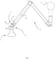
- Fig. 1 illustrates an extractor tubing 2 comprising a damper adjusting arrangement 1 according to a first example.
- the extractor tubing 2 is designed for source capturing different gases dust avoiding their expansion in a worksite.
- a suction fan 3 is coupled to a channel 5 of the extractor tubing 2 at a first end.
- a hood 7 is mounted to the extractor tubing 2 at a second end.
- An adjustable tubing joint 9 comprises a pivot mechanism 10 providing that the hood 7 can be pivoted in three-dimension.
- the damper adjusting arrangement 1 comprises a disc shaped element 11 mounted in the channel 5 and configured to be adjustable in fully open state or in a fully closed state or rotated into a holding position there between.
- the damper adjusting arrangement 1 is held in the adjusted position by means of frictional forces of a friction joint between a first and second member (not shown) to keep the disc shaped element 11 in adjusted and held position relative the centre line CL of the channel 5.
- An operator (not shown) can easily turn a knob 13 coupled to the disc shaped element 11 via the friction joint for adjusting the disc shaped element 11 and regulating the flow of gaseous fluid.
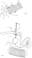
- Fig. 2 illustrates an extractor tubing 2 comprising a damper adjusting arrangement 1 according to a second example.
- the damper adjusting arrangement 1 comprises a disc shaped element 11 rotatable arranged in a channel 5 of the extractor tubing 2.
- the damper adjusting arrangement 1 is configured for regulating the flow of a gaseous fluid within the channel 5.
- the disc shaped element 11 is arranged pivotable arranged together with an axis 12 extending transversely to a centre line CL of the channel 5.
- a knob 13 is positioned exterior the extractor tubing 2 and coupled to the axis 12 for rotating the disc shaped element 11.
- the axis 12 is supported at each end by a respective bearing 14 arranged in the wall of the extractor tubing 2.
- a rotary control mechanism 15 of the damper adjusting arrangement 1 is arranged to the extractor tubing 2 wall.
- a first member (not shown) of the rotary control mechanism 15 comprising a resilient element (not shown), which exhibits a plurality of inward and radially protruding first bulges being configured for engagement with a second member (not shown) of the rotary control means.
- the inward and in radial direction protruding bulges are configured to engage a plurality of outwardly and in radial direction protruding second bulges of a non-resilient second member.
- the second member is configured to be rotatable arranged and coupled to the damper member for providing a rotary motion of the damper member (the disc shaped element 11).
- the geometry of the first bulges may correspond with the geometry of the second bulges.
- a first recess is positioned between two first bulges.
- a second recess is positioned between two second bulges.
- the resilient element When a second bulge or second bulges being positioned in the first recess or in the respective first recess, the resilient element is in a springs back position and holds the second member in position. In such a way, the operator can adjust the damper member to a desired held position (held in position by the resilient member).
- knob 13 For example, if he wants to set a full flow of gaseous fluid through the channel 5, he simply turns the knob 13 to a "fully open” mark (not shown).
- the first bulge is spring-biased into engagement with a second recess.
- Fig. 3 illustrates a damper adjusting arrangement 1 according to a third example in an exploded view.
- the damper adjusting arrangement 1 is configured for regulating the flow of a gaseous fluid within a channel 5 of an extractor tubing 2.
- the damper adjusting arrangement 1 comprises a disc-shaped damper 11 rigidly coupled to a shaft (axis) 12 having square cross-section.
- the shaft 12 is in turn rigidly coupled to a handle 13.
- An operator (not shown) turns the handle 13 for rotating the disc-shaped damper 11.
- a bracket arm 14 configured to hold a pivot mechanism is attached to the extractor tubing 2.
- a first member 21 may be attached to the extractor tubing 2 (e.g. via the bracket arm 14).
- the first member 21 of the damper adjusting arrangement 1 comprises a resilient washer 25, which exhibits a plurality of inwardly protruding first bulges (not shown) being configured for engagement with a second member 23 being rigidly coupled to the shaft 12.
- the second member 23 comprises a plurality of outwardly protruding second bulges (not shown) configured for engagement with said first bulges.
- a respective recess is positioned between two adjacent bulges and when a respective second bulge is moved into a recess between adjacent first bulges, a portion of the resilient washer carrying the first bulges will springs back and hold the second member 23 in position. In such a way, the operator can rotate the disc-shaped damper 11 into a desired held position (thus held in position by the spring back effect of the resilient member).
- Fig. 4 illustrates a damper adjusting arrangement 1 according to a fourth example.
- the damper adjusting arrangement 1 is configured for regulating the flow of a gaseous fluid AF within a channel 5 of an extractor tubing 2.
- the damper adjusting arrangement 1 comprises a disc-shaped damper 11 rigidly coupled to a shaft 12 having square cross-section.
- the shaft 12 is rotatable arranged about an axis extending transverse the centre line of the channel 5 and is rigidly coupled to a knob 13 or wing nut.
- An operator (not shown) turns the knob 13 for rotating the disc-shaped damper 11 for regulating the flow of a gaseous fluid AF.
- a first member 21 may be attached to the extractor tubing 2 by means of rivets 22.
- the first member 21 of the damper adjusting arrangement 1 comprises a resilient washer 25, which exhibits a plurality of inwardly protruding first bulges 31 being configured for engagement with second bulges 33 of a second member 23 (e.g. non-resilient engagement wheel or other circular body) rigidly coupled to the shaft 12.
- the plurality of outwardly protruding second bulges 33 being configured for engagement with said first bulges 31.
- the first and second bulges 31, 33 comprise a common width, wherein at least the first bulge 31 and the second bulge 33 being arranged to interact with each other to provide a discrete stepped control of the rotation of the second member 23, wherein one discrete step corresponds to the width of the respective first 31 and second 33 bulge.
- the second member coupled to the disc shaped element 11 and to the knob 13 can thus be rotated in discrete steps, which makes the damper adjusting arrangement 1 easy to use in a controlled way.
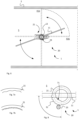
- Figs. 5a and 5b illustrate a first 21 and second 23 member of a damper adjusting arrangement according to a fifth example.
- the first member 21 comprises a washer-like flat element having a central portion occupied by the second member 23.
- the washer-like flat element may be made of high-strength steel and may comprise a first 71 and a second 73 resilient portion, having inwardly protruding first bulges 31, positioned at opposite sides and on both sides of the second member 23.
- the second member 23 is configured as a wheel-like rotary part having the second bulges 33 that protrude outward and are configured to engage the first bulges 31 of the first member 21.
- a rotary axis 12 is coupled to the second member 23.
- the first 21 and second 23 member and a handle or knob (not shown), and the rotary axis may constitute a rotary control means 20 (damper adjustment mechanism).
- the pattern and design of the first 31 and second 33 bulges may be of any suitable shape for reaching a robust and reliable rotary control means 20.
- the respective bulge may be defined as a swelling, a bump, a protrusion, a tooth, a projection, etc.
- a smooth wave-like shape may be used for forming the bulges and recesses.
- a first recess 41 is positioned between two first bulges 31.
- a second recess 43 is positioned between two second bulges 33.
- the respective recess may be defined as a depression, a cavity, a depth, an indentation, a slot, etc.
- the respective first bulge 31 of the respective first 71 and the second 73 resilient portion may be configured to spring away from the second member 23 (as shown in Fig. 5b ) when riding over a corresponding second bulge 33 (during rotation of the second member 23), for subsequently drop down into the second recess 43 of the second member 23, wherein the respective first 71 and the second 73 resilient portion springs back for holding the second member 23 in position.
- the disc shaped element (not shown) coupled to the second member 23 will thus be held in position for regulating the flow of gaseous fluid in the channel (not shown).
- the first bulges 31 being formed along at least one imaginary arc L1, which may follow an imaginary circle, the centre of which corresponds with the axis of the second member 23.
- Reference 81 in Fig. 5b marks a pair of guide arms configured to guide the first member 21 in proper position relative the second member 23.
- Fig. 6 illustrates a damper adjusting arrangement 1 comprising a rotary control means 20 according to a sixth example.
- the damper adjusting arrangement 1 is configured for regulating the flow of a gaseous fluid within a channel 5 of an extractor tubing 2.
- the damper adjusting arrangement 1 comprises a disc-shaped damper 11 rigidly coupled to a shaft 12 and to a handle (not shown).
- a first 21 and second 23 member and the handle and shaft 12 may constitute the rotary control means 20.
- the disc-shaped damper 11 is configured to be rotated by means of the shaft 12 in incremental steps between a fully open state FOS and a fully closed state FCS in said channel 5 of the extractor tubing 2.
- Figs.7a - 7b illustrate different types of inwardly facing bulges of a first member 21 forming a wave-shaped pattern protruding inwardly toward a second member (not shown).
- Fig. 8 illustrates an extractor tubing comprising a damper adjusting arrangement 1 according to a seventh example.
- the damper adjusting arrangement 1 is configured for regulating the flow of a gaseous fluid within a channel 5 of an extractor tubing (not shown).
- the damper adjusting arrangement 1 comprises a damper member 11, which is pivotable arranged in the channel 5 and coupled to a rotary control means 20 mounted to the damper adjusting arrangement 1.
- a first member 21 of the rotary control means 20 comprises a resilient element 71, which exhibits a plurality of radially outwardly protruding first bulges 31 being configured for engagement with a second member 23 of the rotary control means 20.
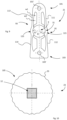
- Fig. 9 illustrates an exemplary first member 21 of a damper adjusting arrangement according to an eight example.
- the first member 21 may be formed as an elongated washer-like planar tongue with a centrally positioned open area A.
- the first member 21 may have a first 91 and second 93 leg connected to a first 101 and a second 103 end portion of the first member 21.
- the first and second leg 91, 93 each comprises a plurality of inwardly facing first bulges 31 forming a wave-shaped pattern.
- the first member can be manufactured as a sheet metal pressed component.
- an imaginary central axis X extends through the central open area A and extends perpendicular to the plane of the elongated washer-like planar tongue.
- the first member 21 comprises the first leg 91 connected to or integrally joined to the first 101 and to the second 103 end portion of the first member 21.
- the first member 21 comprises the second leg 93 connected to or integrally joined to the first 101 and the second 103 end portion of the first member.
- first end portion 101 comprises a first through hole 101' and the second end portion 103 comprises a second through hole 103'.
- the central open area A is configured to encompass the second member (shown in Fig. 10 ).
- the first leg 91 comprises a first flexible portion 111 and a second 112 flexible portion, wherein a first plurality 31' of said first bulges of a first intermediate portion 121 of the first leg 91, is positioned between the first flexible portion 111 and the second 112 flexible portion and being configured to engage the second member.
- the second leg 93 comprises a third flexible portion 113 and a fourth 114 flexible portion, wherein a second plurality 31" of said first bulges a second intermediate portion 123 of the second leg 93, are positioned between the third flexible portion 113 and the fourth flexible portion 114 and being configured to engage the second member.
- the first, second, third and fourth flexible portion 111, 112, 113, 114 exhibiting various thickness and/or width, wherein a first width w1 is wider than a second width w2, for providing a flexibility and/or a resilience of the resilient element.
- Fig. 10 illustrates an exemplary second member 23 of a damper adjusting arrangement according to a ninth example.
- a square shaped through-hole is provided for a shaft 12 coupled to a disc-shaped plate rotatable in a channel (not shown) of an extractor tubing and coupled to a handle or knob.
- the perimeter of an outwardly facing edge area 105 of the second member 23 is oriented coaxial with the shaft 12 and is provided with outwardly and radially protruding second bulges 33.
Landscapes
- Engineering & Computer Science (AREA)
- General Engineering & Computer Science (AREA)
- Mechanical Engineering (AREA)
- Chemical & Material Sciences (AREA)
- Combustion & Propulsion (AREA)
- Air-Flow Control Members (AREA)
Claims (4)
- Dämpfereinstellungsanordnung (1), die dazu ausgestaltet ist, den Strom eines gasförmigen Fluids innerhalb eines Kanals (5) einer Abzugsverrohrung (2) zu regulieren, wobei die Dämpfereinstellungsanordnung (1) ein Dämpferelement (11) umfasst, das in dem Kanal (5) schwenkbar angeordnet und mit Drehsteuerungsmitteln (20) der Dämpfereinstellungsanordnung (1) verbunden ist, wobei ein erstes Element (21) der Drehsteuerungsmittel (20) ein biegsames Element (71, 121) umfasst, das eine Mehrzahl von radial vorstehenden ersten Ausbeulungen (31) aufweist, die dazu ausgestaltet sind, mit einem zweiten Element (23) der Drehsteuerungsmittel (20) in Eingriff zu stehen, dadurch gekennzeichnet, dass das erste Element (21) als längliche unterlegscheibenähnliche planare Zunge mit einem offenen Bereich (A) ausgebildet ist und einen ersten Schenkel (91) und einen zweiten Schenkel (93) aufweist, die mit einem ersten Endabschnitt (101) und einem zweiten Endabschnitt (103) verbunden sind, wobei der erste Schenkel (91) und der zweite Schenkel (93) jeweils eine Mehrzahl von nach innen gerichteten ersten Ausbeulungen (31, 31') umfassen, die ein wellenförmiges Muster bilden, wobei das zweite Element (23) zwischen und in Kontakt mit dem ersten Schenkel (91) und dem zweiten Schenkel (93) positioniert ist, wobei der jeweilige erste Schenkel (91) und zweite Schenkel (93) dazu ausgestaltet ist, gegen das zweite Element (23) federbelastet zu sein.
- Dämpfereinstellungsanordnung (1) nach Anspruch 1, wobei das erste Element (21) eine Mehrzahl von radial und nach innen vorstehenden ersten Ausbeulungen (31) umfasst, die dazu ausgestaltet sind, mit einer zweiten Ausbeulung (33) des zweiten Elements (23) in Eingriff zu stehen.
- Dämpfereinstellungsanordnung (1) nach Anspruch 1 oder 2, wobei das erste Element (21) Stahl umfasst.
- Dämpfereinstellungsanordnung (1) nach einem der Ansprüche 1 bis 3, wobei die ersten Ausbeulungen (31) entlang zumindest eines imaginären kreisförmigen Bogens (L1) ausgebildet sind, der durch den Radius des zweiten Elements (33) definiert ist.
Applications Claiming Priority (2)
| Application Number | Priority Date | Filing Date | Title |
|---|---|---|---|
| CN201920418258.1U CN210118467U (zh) | 2019-03-29 | 2019-03-29 | 阻尼器调节布置 |
| PCT/SE2020/050324 WO2020204791A1 (en) | 2019-03-29 | 2020-03-30 | A damper adjusting arrangement |
Publications (4)
| Publication Number | Publication Date |
|---|---|
| EP3948099A1 EP3948099A1 (de) | 2022-02-09 |
| EP3948099A4 EP3948099A4 (de) | 2022-12-21 |
| EP3948099C0 EP3948099C0 (de) | 2025-03-12 |
| EP3948099B1 true EP3948099B1 (de) | 2025-03-12 |
Family
ID=69612284
Family Applications (1)
| Application Number | Title | Priority Date | Filing Date |
|---|---|---|---|
| EP20784592.6A Active EP3948099B1 (de) | 2019-03-29 | 2020-03-30 | Dämpfereinstellungsanordnung |
Country Status (5)
| Country | Link |
|---|---|
| US (1) | US12234915B2 (de) |
| EP (1) | EP3948099B1 (de) |
| CN (1) | CN210118467U (de) |
| PL (1) | PL3948099T3 (de) |
| WO (1) | WO2020204791A1 (de) |
Family Cites Families (11)
| Publication number | Priority date | Publication date | Assignee | Title |
|---|---|---|---|---|
| NL8602584A (nl) * | 1986-10-15 | 1988-05-02 | Philips Nv | Bestralingsapparaat. |
| US5096156A (en) * | 1991-04-22 | 1992-03-17 | Beutler Heating & Air Conditioning, Inc. | Motorized damper apparatus |
| US7407337B2 (en) * | 2004-06-17 | 2008-08-05 | Micron Technology, Inc. | Cam-locking positioning mechanism |
| CA2492258C (en) * | 2005-01-11 | 2010-03-23 | Venmar Ventilation Inc. | Adjustable damper assembly |
| DE202006011300U1 (de) * | 2006-07-22 | 2007-03-01 | Trox Gmbh | Volumenstromregler |
| JP4418519B1 (ja) * | 2009-05-22 | 2010-02-17 | 直伸 山下 | 角度調整金具 |
| WO2013177166A1 (en) * | 2012-05-21 | 2013-11-28 | Capital Hardware Supply, Inc. | Adjustable regulator and lock device for ductwork damper |
| US10137485B2 (en) | 2015-01-06 | 2018-11-27 | Lincoln Global, Inc. | Integrated workpiece positioning system with integral fume extraction system |
| US10598404B2 (en) * | 2016-06-29 | 2020-03-24 | Research Products Corporation | Damper with adjustable resistance to blade motion |
| US10928095B2 (en) * | 2016-09-02 | 2021-02-23 | Windgate Products Company, Inc. | Standoff regulator |
| CN206247583U (zh) * | 2016-10-09 | 2017-06-13 | 福迈克斯有限公司 | 风门装置 |
-
2019
- 2019-03-29 CN CN201920418258.1U patent/CN210118467U/zh active Active
-
2020
- 2020-03-30 PL PL20784592.6T patent/PL3948099T3/pl unknown
- 2020-03-30 EP EP20784592.6A patent/EP3948099B1/de active Active
- 2020-03-30 WO PCT/SE2020/050324 patent/WO2020204791A1/en not_active Ceased
- 2020-03-30 US US17/598,881 patent/US12234915B2/en active Active
Also Published As
| Publication number | Publication date |
|---|---|
| EP3948099C0 (de) | 2025-03-12 |
| EP3948099A1 (de) | 2022-02-09 |
| EP3948099A4 (de) | 2022-12-21 |
| CN210118467U (zh) | 2020-02-28 |
| PL3948099T3 (pl) | 2025-07-14 |
| WO2020204791A1 (en) | 2020-10-08 |
| US20220178449A1 (en) | 2022-06-09 |
| US12234915B2 (en) | 2025-02-25 |
Similar Documents
| Publication | Publication Date | Title |
|---|---|---|
| US8182226B2 (en) | Built-in swing mechanism of rotary fan | |
| CN108779885B (zh) | 具有交叠滑配接头的被动排出阀组件及形成和安装的方法 | |
| US7741938B2 (en) | Rotary actuator with programmable tactile feedback | |
| JP6472637B2 (ja) | 電動弁 | |
| EP3948099B1 (de) | Dämpfereinstellungsanordnung | |
| WO2004072523A1 (ja) | 電動式コントロールバルブ | |
| CN101579852A (zh) | 保护罩以及具有这种保护罩的电动工具 | |
| CN107687527A (zh) | 具有外部扭力弹簧的被动排气阀 | |
| JP5564567B2 (ja) | 車両シート用取付具 | |
| US8109182B2 (en) | Ratchet tool | |
| EP3420262B1 (de) | Rohrsystem mit verriegelbarem reibgelenk zur einstellung der relativen schwenkpositionierung von rohrabschnitten | |
| EP3810341B1 (de) | Trägerarmanordnung für einen lokalen gasextraktor und lokaler gasextraktor mit einer solchen trägerarmanordnung | |
| AU2026201616A1 (en) | Standoff for ductwork damper assembly, ductwork damper assembly incorporating same and method of assembling ductwork damper assembly | |
| US6487929B2 (en) | Arrangement for rotatably supporting an element rotatable about an axis | |
| JP2007522394A (ja) | 滑り面スリーブを有する、ばねで支持された二要素面シール | |
| JP5247608B2 (ja) | 一方向回転ダンパ並びに該ダンパを備えたヒンジ機構、開閉機構及びレンジフード | |
| TW201709006A (zh) | 旋鈕結構 | |
| WO2006045317A1 (en) | A valve actuator | |
| CN206076131U (zh) | 拨轮机构及使用该拨轮机构的控制装置 | |
| JP3605734B2 (ja) | 自立機能付き回転ダンパ | |
| CN203796628U (zh) | 可安装于玻璃上的换气扇 | |
| EP3627022B1 (de) | Ventil mit voreinstellungselement | |
| JPH0934575A (ja) | 回転つまみの制動力調整機構 | |
| CN101970259B (zh) | 具有两个圆形构件板和一个弹簧的圆形构件 | |
| BE1028876B1 (nl) | Samenstel voor een luchtkanaal in een ventilatiesysteem |
Legal Events
| Date | Code | Title | Description |
|---|---|---|---|
| STAA | Information on the status of an ep patent application or granted ep patent |
Free format text: STATUS: THE INTERNATIONAL PUBLICATION HAS BEEN MADE |
|
| PUAI | Public reference made under article 153(3) epc to a published international application that has entered the european phase |
Free format text: ORIGINAL CODE: 0009012 |
|
| STAA | Information on the status of an ep patent application or granted ep patent |
Free format text: STATUS: REQUEST FOR EXAMINATION WAS MADE |
|
| 17P | Request for examination filed |
Effective date: 20211011 |
|
| AK | Designated contracting states |
Kind code of ref document: A1 Designated state(s): AL AT BE BG CH CY CZ DE DK EE ES FI FR GB GR HR HU IE IS IT LI LT LU LV MC MK MT NL NO PL PT RO RS SE SI SK SM TR |
|
| DAV | Request for validation of the european patent (deleted) | ||
| DAX | Request for extension of the european patent (deleted) | ||
| A4 | Supplementary search report drawn up and despatched |
Effective date: 20221122 |
|
| RIC1 | Information provided on ipc code assigned before grant |
Ipc: B08B 15/04 20060101ALI20221116BHEP Ipc: F24F 13/14 20060101AFI20221116BHEP |
|
| GRAP | Despatch of communication of intention to grant a patent |
Free format text: ORIGINAL CODE: EPIDOSNIGR1 |
|
| STAA | Information on the status of an ep patent application or granted ep patent |
Free format text: STATUS: GRANT OF PATENT IS INTENDED |
|
| INTG | Intention to grant announced |
Effective date: 20241011 |
|
| GRAS | Grant fee paid |
Free format text: ORIGINAL CODE: EPIDOSNIGR3 |
|
| GRAA | (expected) grant |
Free format text: ORIGINAL CODE: 0009210 |
|
| STAA | Information on the status of an ep patent application or granted ep patent |
Free format text: STATUS: THE PATENT HAS BEEN GRANTED |
|
| AK | Designated contracting states |
Kind code of ref document: B1 Designated state(s): AL AT BE BG CH CY CZ DE DK EE ES FI FR GB GR HR HU IE IS IT LI LT LU LV MC MK MT NL NO PL PT RO RS SE SI SK SM TR |
|
| RAP3 | Party data changed (applicant data changed or rights of an application transferred) |
Owner name: FUMEX AB |
|
| REG | Reference to a national code |
Ref country code: GB Ref legal event code: FG4D |
|
| REG | Reference to a national code |
Ref country code: CH Ref legal event code: EP |
|
| REG | Reference to a national code |
Ref country code: DE Ref legal event code: R096 Ref document number: 602020047631 Country of ref document: DE |
|
| REG | Reference to a national code |
Ref country code: IE Ref legal event code: FG4D |
|
| U01 | Request for unitary effect filed |
Effective date: 20250321 |
|
| U07 | Unitary effect registered |
Designated state(s): AT BE BG DE DK EE FI FR IT LT LU LV MT NL PT RO SE SI Effective date: 20250327 |
|
| U20 | Renewal fee for the european patent with unitary effect paid |
Year of fee payment: 6 Effective date: 20250408 |
|
| PG25 | Lapsed in a contracting state [announced via postgrant information from national office to epo] |
Ref country code: RS Free format text: LAPSE BECAUSE OF FAILURE TO SUBMIT A TRANSLATION OF THE DESCRIPTION OR TO PAY THE FEE WITHIN THE PRESCRIBED TIME-LIMIT Effective date: 20250612 |
|
| PGFP | Annual fee paid to national office [announced via postgrant information from national office to epo] |
Ref country code: PL Payment date: 20250428 Year of fee payment: 6 |
|
| PG25 | Lapsed in a contracting state [announced via postgrant information from national office to epo] |
Ref country code: ES Free format text: LAPSE BECAUSE OF FAILURE TO SUBMIT A TRANSLATION OF THE DESCRIPTION OR TO PAY THE FEE WITHIN THE PRESCRIBED TIME-LIMIT Effective date: 20250312 |
|
| PG25 | Lapsed in a contracting state [announced via postgrant information from national office to epo] |
Ref country code: NO Free format text: LAPSE BECAUSE OF FAILURE TO SUBMIT A TRANSLATION OF THE DESCRIPTION OR TO PAY THE FEE WITHIN THE PRESCRIBED TIME-LIMIT Effective date: 20250612 |
|
| PG25 | Lapsed in a contracting state [announced via postgrant information from national office to epo] |
Ref country code: HR Free format text: LAPSE BECAUSE OF FAILURE TO SUBMIT A TRANSLATION OF THE DESCRIPTION OR TO PAY THE FEE WITHIN THE PRESCRIBED TIME-LIMIT Effective date: 20250312 |
|
| PG25 | Lapsed in a contracting state [announced via postgrant information from national office to epo] |
Ref country code: GR Free format text: LAPSE BECAUSE OF FAILURE TO SUBMIT A TRANSLATION OF THE DESCRIPTION OR TO PAY THE FEE WITHIN THE PRESCRIBED TIME-LIMIT Effective date: 20250613 |
|
| PG25 | Lapsed in a contracting state [announced via postgrant information from national office to epo] |
Ref country code: SM Free format text: LAPSE BECAUSE OF FAILURE TO SUBMIT A TRANSLATION OF THE DESCRIPTION OR TO PAY THE FEE WITHIN THE PRESCRIBED TIME-LIMIT Effective date: 20250312 |
|
| PG25 | Lapsed in a contracting state [announced via postgrant information from national office to epo] |
Ref country code: CZ Free format text: LAPSE BECAUSE OF FAILURE TO SUBMIT A TRANSLATION OF THE DESCRIPTION OR TO PAY THE FEE WITHIN THE PRESCRIBED TIME-LIMIT Effective date: 20250312 |
|
| REG | Reference to a national code |
Ref country code: CH Ref legal event code: H13 Free format text: ST27 STATUS EVENT CODE: U-0-0-H10-H13 (AS PROVIDED BY THE NATIONAL OFFICE) Effective date: 20251023 |
|
| PG25 | Lapsed in a contracting state [announced via postgrant information from national office to epo] |
Ref country code: SK Free format text: LAPSE BECAUSE OF FAILURE TO SUBMIT A TRANSLATION OF THE DESCRIPTION OR TO PAY THE FEE WITHIN THE PRESCRIBED TIME-LIMIT Effective date: 20250312 |
|
| PG25 | Lapsed in a contracting state [announced via postgrant information from national office to epo] |
Ref country code: IS Free format text: LAPSE BECAUSE OF FAILURE TO SUBMIT A TRANSLATION OF THE DESCRIPTION OR TO PAY THE FEE WITHIN THE PRESCRIBED TIME-LIMIT Effective date: 20250712 |
|
| PG25 | Lapsed in a contracting state [announced via postgrant information from national office to epo] |
Ref country code: MC Free format text: LAPSE BECAUSE OF FAILURE TO SUBMIT A TRANSLATION OF THE DESCRIPTION OR TO PAY THE FEE WITHIN THE PRESCRIBED TIME-LIMIT Effective date: 20250312 |
|
| PLBE | No opposition filed within time limit |
Free format text: ORIGINAL CODE: 0009261 |
|
| STAA | Information on the status of an ep patent application or granted ep patent |
Free format text: STATUS: NO OPPOSITION FILED WITHIN TIME LIMIT |
|
| PG25 | Lapsed in a contracting state [announced via postgrant information from national office to epo] |
Ref country code: CH Free format text: LAPSE BECAUSE OF NON-PAYMENT OF DUE FEES Effective date: 20250331 |
|
| PG25 | Lapsed in a contracting state [announced via postgrant information from national office to epo] |
Ref country code: IE Free format text: LAPSE BECAUSE OF NON-PAYMENT OF DUE FEES Effective date: 20250330 |
|
| REG | Reference to a national code |
Ref country code: CH Ref legal event code: L10 Free format text: ST27 STATUS EVENT CODE: U-0-0-L10-L00 (AS PROVIDED BY THE NATIONAL OFFICE) Effective date: 20260121 |
|
| 26N | No opposition filed |
Effective date: 20251215 |
|
| U20 | Renewal fee for the european patent with unitary effect paid |
Year of fee payment: 7 Effective date: 20260129 |
|
| PGFP | Annual fee paid to national office [announced via postgrant information from national office to epo] |
Ref country code: GB Payment date: 20260119 Year of fee payment: 7 |