EP3947972B1 - A fully actuated valve for a reciprocating machine and reciprocating machine including said valve - Google Patents
A fully actuated valve for a reciprocating machine and reciprocating machine including said valve Download PDFInfo
- Publication number
- EP3947972B1 EP3947972B1 EP20717553.0A EP20717553A EP3947972B1 EP 3947972 B1 EP3947972 B1 EP 3947972B1 EP 20717553 A EP20717553 A EP 20717553A EP 3947972 B1 EP3947972 B1 EP 3947972B1
- Authority
- EP
- European Patent Office
- Prior art keywords
- valve
- seat
- cage
- closing member
- suction
- Prior art date
- Legal status (The legal status is an assumption and is not a legal conclusion. Google has not performed a legal analysis and makes no representation as to the accuracy of the status listed.)
- Active
Links
Images





Classifications
-
- F—MECHANICAL ENGINEERING; LIGHTING; HEATING; WEAPONS; BLASTING
- F04—POSITIVE - DISPLACEMENT MACHINES FOR LIQUIDS; PUMPS FOR LIQUIDS OR ELASTIC FLUIDS
- F04B—POSITIVE-DISPLACEMENT MACHINES FOR LIQUIDS; PUMPS
- F04B53/00—Component parts, details or accessories not provided for in, or of interest apart from, groups F04B1/00 - F04B23/00 or F04B39/00 - F04B47/00
- F04B53/10—Valves; Arrangement of valves
- F04B53/102—Disc valves
- F04B53/1022—Disc valves having means for guiding the closure member axially
-
- F—MECHANICAL ENGINEERING; LIGHTING; HEATING; WEAPONS; BLASTING
- F04—POSITIVE - DISPLACEMENT MACHINES FOR LIQUIDS; PUMPS FOR LIQUIDS OR ELASTIC FLUIDS
- F04B—POSITIVE-DISPLACEMENT MACHINES FOR LIQUIDS; PUMPS
- F04B39/00—Component parts, details, or accessories, of pumps or pumping systems specially adapted for elastic fluids, not otherwise provided for in, or of interest apart from, groups F04B25/00 - F04B37/00
- F04B39/08—Actuation of distribution members
-
- F—MECHANICAL ENGINEERING; LIGHTING; HEATING; WEAPONS; BLASTING
- F04—POSITIVE - DISPLACEMENT MACHINES FOR LIQUIDS; PUMPS FOR LIQUIDS OR ELASTIC FLUIDS
- F04B—POSITIVE-DISPLACEMENT MACHINES FOR LIQUIDS; PUMPS
- F04B39/00—Component parts, details, or accessories, of pumps or pumping systems specially adapted for elastic fluids, not otherwise provided for in, or of interest apart from, groups F04B25/00 - F04B37/00
- F04B39/10—Adaptations or arrangements of distribution members
-
- F—MECHANICAL ENGINEERING; LIGHTING; HEATING; WEAPONS; BLASTING
- F04—POSITIVE - DISPLACEMENT MACHINES FOR LIQUIDS; PUMPS FOR LIQUIDS OR ELASTIC FLUIDS
- F04B—POSITIVE-DISPLACEMENT MACHINES FOR LIQUIDS; PUMPS
- F04B39/00—Component parts, details, or accessories, of pumps or pumping systems specially adapted for elastic fluids, not otherwise provided for in, or of interest apart from, groups F04B25/00 - F04B37/00
- F04B39/10—Adaptations or arrangements of distribution members
- F04B39/1053—Adaptations or arrangements of distribution members the members being Hoerbigen valves
-
- F—MECHANICAL ENGINEERING; LIGHTING; HEATING; WEAPONS; BLASTING
- F16—ENGINEERING ELEMENTS AND UNITS; GENERAL MEASURES FOR PRODUCING AND MAINTAINING EFFECTIVE FUNCTIONING OF MACHINES OR INSTALLATIONS; THERMAL INSULATION IN GENERAL
- F16K—VALVES; TAPS; COCKS; ACTUATING-FLOATS; DEVICES FOR VENTING OR AERATING
- F16K31/00—Actuating devices; Operating means; Releasing devices
- F16K31/02—Actuating devices; Operating means; Releasing devices electric; magnetic
- F16K31/06—Actuating devices; Operating means; Releasing devices electric; magnetic using a magnet, e.g. diaphragm valves, cutting off by means of a liquid
- F16K31/0675—Electromagnet aspects, e.g. electric supply therefor
-
- Y—GENERAL TAGGING OF NEW TECHNOLOGICAL DEVELOPMENTS; GENERAL TAGGING OF CROSS-SECTIONAL TECHNOLOGIES SPANNING OVER SEVERAL SECTIONS OF THE IPC; TECHNICAL SUBJECTS COVERED BY FORMER USPC CROSS-REFERENCE ART COLLECTIONS [XRACs] AND DIGESTS
- Y02—TECHNOLOGIES OR APPLICATIONS FOR MITIGATION OR ADAPTATION AGAINST CLIMATE CHANGE
- Y02P—CLIMATE CHANGE MITIGATION TECHNOLOGIES IN THE PRODUCTION OR PROCESSING OF GOODS
- Y02P10/00—Technologies related to metal processing
- Y02P10/25—Process efficiency
Definitions
- Embodiments disclosed herein generally relate to actuated valves for reciprocating machines, specifically for reciprocating compressors.
- Compressors are machines used to increase the pressure of a compressible fluid; their use is widespread in several technical fields, among which in particular oil and gas industry.
- WO 2012/122203 A2 discloses a controller actuator.
- WO 2011/009880 A1 discloses a suction valve.
- DE 10 39 326 B discloses a plate valve.
- EP 2 206 941 A1 discloses an actuated valve.
- WO 2016/184827 A1 discloses a poppet valve.
- Compressors may be classified in two main categories, namely dynamic compressors and positive displacement compressors.
- dynamic compressors the gas is compressed by transferring kinetic energy from a rotating element, such as an impeller or a bladed wheel, to the gas being compressed. The kinetic energy of the gas is then converted into pressure by slowing the gas.
- Typical dynamic compressors are centrifugal compressors and axial compressors.
- positive displacement compressors the gas pressure is increased by trapping the gas in a volume and reducing the volume.
- Exemplary positive displacement compressors are screw compressors, vane compressors and reciprocating compressors.
- Reciprocating compressors comprise a cylinder and a piston slidingly arranged in the cylinder for reciprocatingly moving therein.
- the piston and the cylinder form a single or a double compression chamber. If a single compression chamber is formed, the reciprocating compressor is termed single-acting reciprocating compressor. If two compression chambers are defined by the cylinder and the piston, the compressor is referred to as a double-acting reciprocating compressor.
- Each compression chamber is fluidly coupled to a suction duct or to a suction plenum to suck compressible fluid therefrom, and to a delivery duct or to a delivery plenum, to deliver compressed fluid therein.
- Each compression chamber comprises at least one suction valve adapted to selectively place the compression chamber in fluid communication with the suction duct or the suction plenum.
- Each compression chamber further comprises at least one discharge valve adapted to selectively place the compression chamber in fluid communication with the discharge duct or the discharge plenum.
- reciprocating compressors use automatic suction valves and automatic discharge valves.
- a valve closing member is biased in a closing position by one or more resilient members, such as coil springs.
- the valve opens when the difference of the fluid pressures acting upon opposing sides of the closing member overcomes the resilient force applied by the resilient member.
- valves for reciprocating compressors are actuated by connecting the closing member to an actuator. In this way opening and closing of the valve can be controlled at least during part of the compression cycle, independently of the pressure differential across the valve.
- actuated valves in reciprocating compressors are disclosed in US2013/0160641 and US2007/0272890 .
- Actuated valves are used for instance as suction valves.
- the actuator of the suction valve can act upon the suction valve such that the valve is maintained in the open condition during at least a fraction of the compression phase. This control is used to modulate the flowrate of reciprocating compressors.
- the suction valve is forced in the open position, such that part of the fluid collected in the compression chamber flows back through the suction duct or suction plenum, and the amount of gas compressed in each compression cycle is reduced.
- the flowrate of the compressor can thus be modulated.
- US 2 957 620 A , US 2 907 344 A , US 1 769 899 A and FR 768 331 A are further examples for suction and delivery valves suitable for reciprocating machines. They differ in the general construction of the valve seat, cage and guide and the way their parts are meant to be arranged in the reciprocating machine.
- Actuated valves of the current art are cumbersome and can be prone to malfunctioning.
- the present invention concerns a valve for a reciprocating machine, comprising a seat provided with flow apertures therein.
- the valve further includes a valve closing member, adapted to co-act with the seat for selectively closing and opening said apertures.
- a cage is integrally coupled to said seat.
- the cage and the seat are formed monolithically as a single body in one and the same manufacturing step, for instance by additive manufacturing.
- the cage and the seat can be manufactured separately and thereafter connected rigidly to one another to form an integral body, i.e. a rigid component.
- the valve closing member comprises an actuation stem, slidingly arranged in a guide integrally connected to the cage.
- the guide can be in the form of a tube, i.e. can be a tubular guide.
- the guide and the cage can be manufactured as a single monolithic body, for instance in a single manufacturing step by additive manufacturing.
- the guide and the cage can be manufactured separately and coupled afterwards into a single integral body.
- the guide and the seat can be manufactured integrally and monolithically in a single manufacturing step, e.g. by additive manufacturing. In other embodiments, the guide and the seat can be manufactured separately and then made to a single integral piece by subsequent coupling.
- the valve can further comprise a cover coupled with the cage,
- the actuation stem of the valve closing member can extend through the cover, such that a distal end of the stem, i.e. an end opposite the closing plate thereof, is accessible for connection to a valve actuator arranged outside the reciprocating machine and outside the cover.
- the valve can comprise a sealing arrangement housed in the guide and co-acting with the actuation stem, to prevent or limit gas leakages along the actuation stem of the valve closing member.
- the actuation stem extends through the seat.
- valve When the valve is designed as a suction valve, it may further comprise a guard.
- the valve closing member can then be arranged between the seat and the guard and adapted to move therebetween from a valve close position to a valve open position.
- the seat of the valve can have a replaceable seat plate, for instance made of metal or, in some particularly advantageous embodiments, made of a polymeric material.
- the replaceable seat plate is located on the side of the seat facing the valve closing member, such that this latter is arranged to contact the replaceable seat plate when the valve closing member is in a valve closing position.
- a reciprocating machine in particular a reciprocating compressor, comprising a cylinder and a piston arranged in the cylinder, reciprocatingly moving therein.
- the cylinder and the piston form at least one compressor chamber, or preferably two compression chambers of a double-acting reciprocating compressor.
- the reciprocating machine further includes at least one suction valve and at least one deliver valve, both fluidly coupled to the compression chamber. At least one of said valves is designed as described above.
- the valve is particularly useful as a suction valve and can be useful as a discharge valve in reciprocating compressors.
- the valve includes a cage and a valve closing member, i.e. a shutter.
- the valve closing member is adapted to be drivingly coupled to a control actuator.
- the valve closing member has an actuation stem, which is guided in a guide integrally formed with the cage of the valve. Effective guidance of the valve closing member is thus obtained.
- Fig.1 schematically shows a double-acting reciprocating compressor 1.
- the reciprocating compressor 1 comprises a cylinder 3 and a piston 5 arranged in the cylinder 3 and adapted to reciprocatingly move therein when the compressor is in use.
- the piston 5 and the cylinder 3 form two compressor chambers 7A, 7B where a gaseous fluid to be compressed is cyclically sucked and compressed.
- the rotary motion of the crank shaft 9 is converted into reciprocating translation motion by a connecting rod 11 ad a crosshead 13, which is connected to the piston 5 by a piston rod 15.
- Each compression chamber 7A, 7B is provided with at least one suction valve 21 and one delivery or discharge valve 23, respectively.
- the suction valves 21 can be fluidly coupled to a suction plenum 25, from which a gaseous fluid at a first, lower pressure P1 is sucked alternatively in the first and second compression chambers 7A, 7B.
- the discharge valves 23 can be fluidly coupled to a discharge plenum 27, into which the gaseous fluid is discharged at a second, higher pressure P2.
- a respective actuator for example an electro-magnetic actuator 29, controls each suction valve 21.
- a respective actuator, for instance an electro-magnetic actuator 31, controls each discharge valve 23. Suitable electro-magnetic actuators are disclosed in US2007/0272890 .
- the piston 5 moves reciprocatingly according to double arrow f5 inside the cylinder 3 such that gas is cyclically sucked through suction valves 21 at suction pressure P1 and discharged at discharge pressure P2 through discharge valves 23. Opening and closing of the suction valves 21 and discharge valve 23 is controlled by actuators 29 and 31. A more precise control of the compression cycle and of the compressor flowrate can be achieved.
- one, some of all the suction valves 21, or one, some or all discharge valves 23 can be automatic valves.
- the suction valves 21 can be fully actuated valves, while the discharge valves 23 can be automatic valves.
- Actuators on one, some or all suction valves 21 may be used to better control the compressor flowrate.
- FIG.1 Figs.2 , 3 , 4 and 5 illustrate an exemplary embodiment of a suction valve 21, and the way it can be mounted on the compressor cylinder 3.
- the suction valve 21 includes a casing or cage 33, which has a set of posts 35 extending between a cover 37 and a seat 39.
- the posts define flow passages, such that when the valve 21 is arranged in fluid communication with the suction duct or plenum 25, gas can enter the valve and flow therethrough.
- the seat 39 can include a plurality of suction apertures or ports 41.
- the apertures 41 can be in the form of elongated and curved ports arranged according to circumferential concentric lines, coaxial with the valve axis A-A.
- the seat 39 can include a replaceable seat plate 43, which is provided with ports or apertures 46, having the same shape and position as the ports 41.
- a pin 44 can be used to mount the replaceable seat plate 43 in the correct angular position, such that the apertures 46 and 41 are mutually aligned.
- a ferrule 42 can be provided to mount the replaceable seat plate 43 on the seat 39.
- the cover 37 can be provided with an annular groove 37A adapted to receive an O-ring or any other gasket or sealing member, which provides a seal between the suction valve 21 and the compressor cylinder 3 when the valve 21 is mounted, see Fig.5 .
- the suction valve 21 further comprises a valve closing member 45 also referred to as shutter.
- the valve closing member 45 is illustrated in detail in Fig. 4 , separated from the suction valve 21.
- the valve closing member 45 comprises a plate 47 and a stem 49.
- the plate 47 includes a plurality of apertures or ports 51, which are shifted with respect to the suction apertures 41, such that the solid (non-perforated) portions of the plate 47 close the suction apertures 41 when the valve closing member 45 is in the closed position, in abutment against the replaceable seat plate 43.
- a transverse pin 53 can be provided along the stem 49, said pin slidingly engaging a slot 57 machined in the seat 49.
- the valve closing member 45 can be manufactured as a single component, for instance by additive manufacturing. This may reduce manufacturing costs. In other embodiments, however, the plate 47 and the stem 49 can be manufactured separately and then coupled together, e.g. by welding, gluing, soldering, or else by way of screws or bolts.
- the valve closing member 45 can be manufactured in metal material. In other embodiments, use of polymeric material is not excluded.
- the stem 49 can be hollow (see hole 49A) in order to reduce the mass and therefore the inertia thereof.
- the axial hole 49A can be closed at the end facing the interior of the compression chamber, to reduce the clearance volume of the compressor.
- a honeycomb or other stiffening structure can be provided inside the axial hole 49A. Such structure can easily be manufactured e.g. by additive manufacturing.
- the plate 47 has a convex lower surface. This can be useful for stiffening the plate 47, since the thickness thereof increases moving radially from the periphery towards the center.
- the plate 47 can be flat ( Fig.4 ).
- the stem 49 extends through the cover 37 such that an end 49B of the stem 49, opposite the plate 47, is accessible from the exterior of the suction valve 21 for coupling to the actuator 29.
- valve closing member 45 is controlled in a reciprocating motion according to double arrow f45 by the actuator 29.
- the stem 49 can be slidingly movable in a guide 59.
- the guide 59 is in the form of a tubular guide, which can extend from the seat 39 to the cover 37.
- the stem 49 may include one or more annular projections 49C, 49D, forming respective sliding surfaces, in sliding contact with the inner surface of the tubular guide 59.
- the annular projections 49C, 49D are distanced from one another along the axial extension of the stem 49, such that better guidance is achieved. A smooth and efficient guiding action on the stem 49 is thus obtained and buckling of the stem during movement thereof is prevented.
- a sealing arrangement 61 is provided along the tubular guide 49 and/or in the cover 37 .
- the sealing arrangement 61 can be mounted in an axial seat formed in the cover 37 and/or in the tubular guide 59 by means of a lock nut or any other suitable lock member 63.
- the lock member 63 has an axial hole, through which the stem 49 extends, such that the distal end 49B thereof projects outside the suction valve 21 for connection to the actuator 29 (see Fig.5 ).
- valve closing member 45 By providing a sealing arrangement 61 within the tubular guide 59 and/or the cover 37 a compact valve is obtained, with a reduced axial length.
- the reduction of the axial extension of the valve members also reduces the total weight of the valve and the weight of the reciprocatingly moving part thereof, namely the valve closing member 45.
- a gas recovery duct 65 can be integrated in the valve cage or casing.
- the gas recovery duct 65 is adapted to recover any gas leakage along the tubular guide 59.
- By arranging the gas recovery duct 65 inside the structure of the valve cage a compact structure is obtained.
- the gas recovery duct 65 can end with a connection 65A arranged outside the compressor cylinder and that can be fluidly coupled to a gas recovery circuit, not shown.
- the cage 33 and the cover 37 of the suction valve 21 can be manufactured as a single monolithic block.
- the cage 33 and the seat 39, excluding the replaceable seat plate 43, if provided can be manufactured as a single monolithic body.
- the cage 33 and the tubular guide 59 can be manufactured as a single monolithic body.
- the cage 33, including the posts 35, the seat 39, the tubular guide 59 and the cover 37 are formed as a single monolithic body, preferably in one and the same material, for instance metal.
- the replaceable seat plate 43 can be manufactured in a polymeric material or metallic material.
- the polymeric material being softer, impact forces generated by the valve closing member 45 are absorbed and a higher reliability is achieved. Wear is concentrated on the replaceable seat plate, which is less expensive than the valve closing member 45.
- the valve closing member 45 can be advantageously made of a polymeric material, for shock absorption and wear concentration purposes. Polymeric, rather than metallic material for manufacturing the valve closing member 45 is also beneficial in terms of reduced mass of such reciprocatingly movable member.
- the above mentioned components of the suction valve 21 can be manufactured by additive manufacturing.
- Any additive manufacturing process suitable for the metal material used for this kind of component and adapted to achieve the desired final properties of the component can be used.
- additive layer deposition, or powder bed fusion (PBF) can be used, such as by direct metal laser melting (DMLM), electron beam melting (EBM), directed metal laser sintering (DMLS), selective laser melting (SLM), selective laser sintering (SLS) or selective heat sintering (SHS).
- DMLM direct metal laser melting
- EBM electron beam melting
- DMLS directed metal laser sintering
- SLM selective laser melting
- SLS selective laser sintering
- SHS selective heat sintering
- two or more sections or parts of the stationary components of the valve can be manufactured separately and then assembled to one another, e.g. by soldering or welding to obtain a final component.
- valve assembly By integrating several components of the suction valve 21 in a single body, handling of the valve and assembling thereof in the compressor 1 become simpler and faster and require less technical expertise.
- the entire valve assembly, including the valve closing member 45 and the replaceable seat plate can be pre-assembled outside the cylinder, and subsequently mounted and fixed to the compressor cylinder by simply screwing bolts through holes 37A of cover 37 (see Fig.5 ).
- suction valve 21 can be of the so-called "closed type".
- Suction valves of the closed type are provided with a guard, which is arranged in front of the valve closing member 45, opposite the seat 39. The plate 47 of the valve closing member 45 is thus reciprocatingly movable between the seat and the guard.
- a suction valve of the closed type is shown in Fig. 6 .
- the same reference numbers indicate the same parts as already described above in connection with Figs. 2 , 3 , 4 and 5 ; these parts will not be described again.
- valve of the open type shown in Figs. 1 , 2 , 3 , 4 and 5 and the closed type valve of Fig.6 is that this latter includes a guard 71 provided with ports or apertures 72, which are aligned with the ports or apertures 51 of the plate 47 of the valve closing member 45.
- the plate 47 of the valve closing member 45 is adapted to move axially between the surface of the guard 71 facing the plate 47 and the replaceable seat plate 43 of the seat 39, i.e. between an open position (plate 47 resting on guard 71) and a closed position (plate 47 resting on the replaceable seat plate 43).
- the guard 71 can be integral with the ferrule 42 which retains the replaceable seat plate 43 on the valve seat 39.
- the discharge valve 23 comprises a cage 81 with posts 83 which extend between a cover 85 and a seat 87.
- the seat 87 is provided with a plurality of discharge apertures or ports 89.
- the posts 83 can be connected to the seat 87.
- the ports 89 of the seat 87 can be selectively opened and closed by a valve closing member 91, also referred to as shutter, which is adapted to reciprocatingly move according to double arrow f91 between an open position and a closed position.
- the valve closing member 91 comprises a plate 93 and a stem 95.
- the plate 93 is provided with ports or apertures 97 which are offset with respect to the apertures or ports 89, such that when the plate 93 is urged against the seat 87 the apertures 89 are closed by the plate 93; when the plate 93 is distanced from the seat 87 compressed gas can flow through the apertures 89 and 97 towards the discharge plenum 27 of the compressor 1.
- pins can be provided in order to mount the seat 87 and the valve closing member 91 in the correct mutual angular position, such that elongated and curved apertures or ports 97 and 89 will be in the correct mutual position.
- the stem 95 is slidingly housed in a tubular guide 99 and can project beyond the cover 85, such that the end 95A of the stem 95 can be coupled to the actuator 31 ( Fig. 1 ; not shown in Fig.7 ).
- stem 95 can be provided with annular portions 95A forming surfaces in sliding and guiding contact with the inner surface of the tubular guide 99.
- a sealing arrangement 100 similar to the sealing arrangement 66, can be arranged in the tubular guide 99.
- the cage 21, the tubular guide 99 and possibly the cover 85 can be formed as a single monolithic body, for instance by additive manufacturing, or else by soldering or welding separate components (cover and cage) together.
- a further embodiment of a suction valve is shown in Fig.8 .
- the suction valve of Fig. 8 is again labeled 21 as a whole.
- the suction valve 21 includes a casing or cage 133 which has a set of posts 135 extending between a cover 137 and a seat 139.
- the posts 133 can have portions which are perpendicular to the seat 139 and portions which are inclined and converge towards each other near the cover 137.
- the seat 139 can include a plurality of suction apertures or ports 141.
- the apertures 141 can be in the form of elongated and curved ports arranged according to circumferential concentric lines, coaxial with the valve axis A-A.
- the seat 139 can include a replaceable seat plate 143, which is provided with ports or apertures 146, having the same shape and position as the ports 141.
- a ferrule 142 can be provided to mount the replaceable seat plate 143 on the seat 139.
- the cover 137 can be provided with an annular groove 137A adapted to receive an O-ring or any other gasket or sealing member, not shown, which provides a seal between the suction valve 21 and the compressor cylinder 3 when the valve is mounted.
- the suction valve 21 of Fig.8 further comprises a valve closing member, i.e. a shutter 145.
- the valve closing member 145 comprises a plate 147 and a stem 149.
- the plate 147 includes a plurality of apertures or ports 151 which are shifted with respect to the suction apertures 141, such that the solid (non-perforated) portions of the plate 147 will close the suction apertures 141 when the valve closing member 145 is in the closed position, in abutment against the replaceable seat plate 143.
- the valve closing member 145 can be manufactured as a single component, for instance by additive manufacturing. This may reduce manufacturing costs. In other embodiments, however, the plate 147 and the stem 149 can be manufactured separately and then bonded together, e.g. by welding, gluing, soldering, or else by way of screws or bolts.
- the stem 149 can be hollow (see hole 149A), in order to reduce the mass and therefore the inertia thereof.
- stem 149 can include a honeycomb structure or other stiffening structure in the axial hole 149A. Such structure can easily be manufactured e.g. by additive manufacturing.
- the stem 149 extends through the cover 137 such that an end 149B of the stem 149, opposite the plate 147, is accessible from the exterior of the suction valve 21 for coupling to the actuator 129.
- the stem 149 is slidingly movable in a tubular guide 159, which can extend from the seat 139 to the cover 137.
- the stem 149 may include one or more annular projections forming respective sliding surfaces, in sliding contact with the inner surface of the tubular guide 159.
- a sealing arrangement 161 is provided, similarly to other embodiments disclosed above.
Landscapes
- Engineering & Computer Science (AREA)
- Mechanical Engineering (AREA)
- General Engineering & Computer Science (AREA)
- Compressor (AREA)
- Lift Valve (AREA)
- Details Of Valves (AREA)
- Fluid-Pressure Circuits (AREA)
- Mechanically-Actuated Valves (AREA)
Description
- Embodiments disclosed herein generally relate to actuated valves for reciprocating machines, specifically for reciprocating compressors.
- Compressors are machines used to increase the pressure of a compressible fluid; their use is widespread in several technical fields, among which in particular oil and gas industry.
-
WO 2012/122203 A2 discloses a controller actuator.WO 2011/009880 A1 discloses a suction valve.DE 10 39 326 B discloses a plate valve.EP 2 206 941 A1 discloses an actuated valve.WO 2016/184827 A1 discloses a poppet valve. - Compressors may be classified in two main categories, namely dynamic compressors and positive displacement compressors. In dynamic compressors the gas is compressed by transferring kinetic energy from a rotating element, such as an impeller or a bladed wheel, to the gas being compressed. The kinetic energy of the gas is then converted into pressure by slowing the gas. Typical dynamic compressors are centrifugal compressors and axial compressors. In positive displacement compressors the gas pressure is increased by trapping the gas in a volume and reducing the volume. Exemplary positive displacement compressors are screw compressors, vane compressors and reciprocating compressors.
- Reciprocating compressors comprise a cylinder and a piston slidingly arranged in the cylinder for reciprocatingly moving therein. The piston and the cylinder form a single or a double compression chamber. If a single compression chamber is formed, the reciprocating compressor is termed single-acting reciprocating compressor. If two compression chambers are defined by the cylinder and the piston, the compressor is referred to as a double-acting reciprocating compressor. Each compression chamber is fluidly coupled to a suction duct or to a suction plenum to suck compressible fluid therefrom, and to a delivery duct or to a delivery plenum, to deliver compressed fluid therein.
- Each compression chamber comprises at least one suction valve adapted to selectively place the compression chamber in fluid communication with the suction duct or the suction plenum. Each compression chamber further comprises at least one discharge valve adapted to selectively place the compression chamber in fluid communication with the discharge duct or the discharge plenum.
- Usually, reciprocating compressors use automatic suction valves and automatic discharge valves. In an automatic valve a valve closing member is biased in a closing position by one or more resilient members, such as coil springs. The valve opens when the difference of the fluid pressures acting upon opposing sides of the closing member overcomes the resilient force applied by the resilient member.
- In some embodiments, for better control of the suction, compression and discharge phases of the compression cycle, valves for reciprocating compressors are actuated by connecting the closing member to an actuator. In this way opening and closing of the valve can be controlled at least during part of the compression cycle, independently of the pressure differential across the valve. Exemplary embodiments of actuated valves in reciprocating compressors are disclosed in
US2013/0160641 andUS2007/0272890 . Actuated valves are used for instance as suction valves. The actuator of the suction valve can act upon the suction valve such that the valve is maintained in the open condition during at least a fraction of the compression phase. This control is used to modulate the flowrate of reciprocating compressors. During a portion of the compression stroke of the piston, the suction valve is forced in the open position, such that part of the fluid collected in the compression chamber flows back through the suction duct or suction plenum, and the amount of gas compressed in each compression cycle is reduced. The flowrate of the compressor can thus be modulated. -
US 2 957 620 A ,US 2 907 344 A ,US 1 769 899 A andFR 768 331 A - Actuated valves of the current art are cumbersome and can be prone to malfunctioning.
- Improvements in actuated valves for reciprocating machines, to ameliorate the overall efficiency of the valves, or more generally to remove or alleviate one or more of the drawbacks of the valves of the current art would therefore be welcomed.
- The present invention is defined in the accompanying claims.
- The present invention concerns a valve for a reciprocating machine, comprising a seat provided with flow apertures therein. The valve further includes a valve closing member, adapted to co-act with the seat for selectively closing and opening said apertures. A cage is integrally coupled to said seat. In some embodiments, the cage and the seat are formed monolithically as a single body in one and the same manufacturing step, for instance by additive manufacturing. In other embodiments, the cage and the seat can be manufactured separately and thereafter connected rigidly to one another to form an integral body, i.e. a rigid component.
- In some embodiments, the valve closing member comprises an actuation stem, slidingly arranged in a guide integrally connected to the cage. The guide can be in the form of a tube, i.e. can be a tubular guide.
- In particularly advantageous embodiments, the guide and the cage can be manufactured as a single monolithic body, for instance in a single manufacturing step by additive manufacturing. In less advantageous embodiments, the guide and the cage can be manufactured separately and coupled afterwards into a single integral body.
- In some embodiments, the guide and the seat can be manufactured integrally and monolithically in a single manufacturing step, e.g. by additive manufacturing. In other embodiments, the guide and the seat can be manufactured separately and then made to a single integral piece by subsequent coupling.
- The valve can further comprise a cover coupled with the cage, The actuation stem of the valve closing member can extend through the cover, such that a distal end of the stem, i.e. an end opposite the closing plate thereof, is accessible for connection to a valve actuator arranged outside the reciprocating machine and outside the cover.
- In particularly advantageous embodiments, the valve can comprise a sealing arrangement housed in the guide and co-acting with the actuation stem, to prevent or limit gas leakages along the actuation stem of the valve closing member.
- In some embodiments, specifically when the valve is a suction valve, the actuation stem extends through the seat.
- When the valve is designed as a suction valve, it may further comprise a guard. The valve closing member can then be arranged between the seat and the guard and adapted to move therebetween from a valve close position to a valve open position.
- The seat of the valve can have a replaceable seat plate, for instance made of metal or, in some particularly advantageous embodiments, made of a polymeric material. The replaceable seat plate is located on the side of the seat facing the valve closing member, such that this latter is arranged to contact the replaceable seat plate when the valve closing member is in a valve closing position.
- According to another aspect, disclosed herein is a reciprocating machine, in particular a reciprocating compressor, comprising a cylinder and a piston arranged in the cylinder, reciprocatingly moving therein. The cylinder and the piston form at least one compressor chamber, or preferably two compression chambers of a double-acting reciprocating compressor. The reciprocating machine further includes at least one suction valve and at least one deliver valve, both fluidly coupled to the compression chamber. At least one of said valves is designed as described above.
- Further features and embodiments of the valves and of the reciprocating machine according to the present invention are set forth in the appended claims and will be described in greater detail here on, reference being made to the attached drawings.
- A more complete appreciation of the disclosed embodiments of the invention and many of the attendant advantages thereof will be readily obtained as the same becomes better understood by reference to the following detailed description when considered in connection with the accompanying drawings, wherein:
-
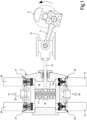
Fig. 1 shows a sectional view of an exemplary double-acting reciprocating compressor including actuated valves according to the present invention, -
Fig.2 shows a side view of an open suction valve; -
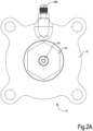
Fig.2A is a top plan view according to line IIA-IIA ofFig.2 ; -
Fig.3 shows a sectional view according to line III-III ofFig.2 ; -
Fig.4 shows a valve closing member of the valve ofFigs 1 and2 ; -
Fig.5 shows a detail of a compressor cylinder with a suction valve ofFigs 2 and3 and relevant actuator mounted thereon; -
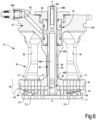
Fig. 6 shows a sectional view of a suction valve according to a further embodiment of the present invention, -
Fig.7 shows a sectional view of a discharge valve according to the present invention, and -
Fig.8 shows a sectional view of a further embodiment of a suction valve. - An actuated valve for reciprocating machines is disclosed herein. The valve is particularly useful as a suction valve and can be useful as a discharge valve in reciprocating compressors. The valve includes a cage and a valve closing member, i.e. a shutter. The valve closing member is adapted to be drivingly coupled to a control actuator. The valve closing member has an actuation stem, which is guided in a guide integrally formed with the cage of the valve. Effective guidance of the valve closing member is thus obtained. Several additional features of exemplary embodiments and relevant advantages thereof will be described in more detail here below, reference being made to the accompanying drawings.
- In the following description embodiments of reciprocating compressor valves will be described. Those skilled in the art will however understand that the actuated valves disclosed herein can be used with advantage also in other reciprocating machines.
-
Fig.1 schematically shows a double-actingreciprocating compressor 1. Thereciprocating compressor 1 comprises acylinder 3 and apiston 5 arranged in thecylinder 3 and adapted to reciprocatingly move therein when the compressor is in use. Thepiston 5 and thecylinder 3 form twocompressor chambers crank shaft 9, drivingly coupled to a driver, not shown, transmits motion to thepiston 5. The rotary motion of thecrank shaft 9 is converted into reciprocating translation motion by a connectingrod 11 ad acrosshead 13, which is connected to thepiston 5 by apiston rod 15. - Each
compression chamber suction valve 21 and one delivery ordischarge valve 23, respectively. Thesuction valves 21 can be fluidly coupled to asuction plenum 25, from which a gaseous fluid at a first, lower pressure P1 is sucked alternatively in the first andsecond compression chambers discharge valves 23 can be fluidly coupled to a discharge plenum 27, into which the gaseous fluid is discharged at a second, higher pressure P2. A respective actuator, for example an electro-magnetic actuator 29, controls eachsuction valve 21. A respective actuator, for instance an electro-magnetic actuator 31, controls eachdischarge valve 23. Suitable electro-magnetic actuators are disclosed inUS2007/0272890 . - In operation, the
piston 5 moves reciprocatingly according to double arrow f5 inside thecylinder 3 such that gas is cyclically sucked throughsuction valves 21 at suction pressure P1 and discharged at discharge pressure P2 throughdischarge valves 23. Opening and closing of thesuction valves 21 anddischarge valve 23 is controlled byactuators - While in
Fig. 1 both thesuction valves 21 and thedischarge valves 23 are fully actuated byactuators suction valves 21, or one, some or all dischargevalves 23 can be automatic valves. For instance, thesuction valves 21 can be fully actuated valves, while thedischarge valves 23 can be automatic valves. Actuators on one, some or allsuction valves 21 may be used to better control the compressor flowrate. - With continuing reference to
Fig.1 ,Figs.2 ,3 ,4 and5 illustrate an exemplary embodiment of asuction valve 21, and the way it can be mounted on thecompressor cylinder 3. - In the embodiment of
Figs. 2 ,3 and4 thesuction valve 21 includes a casing orcage 33, which has a set ofposts 35 extending between acover 37 and aseat 39. The posts define flow passages, such that when thevalve 21 is arranged in fluid communication with the suction duct orplenum 25, gas can enter the valve and flow therethrough. Theseat 39 can include a plurality of suction apertures orports 41. Theapertures 41 can be in the form of elongated and curved ports arranged according to circumferential concentric lines, coaxial with the valve axis A-A. Theseat 39 can include areplaceable seat plate 43, which is provided with ports orapertures 46, having the same shape and position as theports 41. Apin 44 can be used to mount thereplaceable seat plate 43 in the correct angular position, such that theapertures ferrule 42 can be provided to mount thereplaceable seat plate 43 on theseat 39. - The
cover 37 can be provided with anannular groove 37A adapted to receive an O-ring or any other gasket or sealing member, which provides a seal between thesuction valve 21 and thecompressor cylinder 3 when thevalve 21 is mounted, seeFig.5 . - The
suction valve 21 further comprises avalve closing member 45 also referred to as shutter. Thevalve closing member 45 is illustrated in detail inFig. 4 , separated from thesuction valve 21. Thevalve closing member 45 comprises aplate 47 and astem 49. Theplate 47 includes a plurality of apertures orports 51, which are shifted with respect to thesuction apertures 41, such that the solid (non-perforated) portions of theplate 47 close thesuction apertures 41 when thevalve closing member 45 is in the closed position, in abutment against thereplaceable seat plate 43. In order to mount thevalve closing member 45 in the correct angular position with respect to theseat 39, atransverse pin 53 can be provided along thestem 49, said pin slidingly engaging a slot 57 machined in theseat 49. - The
valve closing member 45 can be manufactured as a single component, for instance by additive manufacturing. This may reduce manufacturing costs. In other embodiments, however, theplate 47 and thestem 49 can be manufactured separately and then coupled together, e.g. by welding, gluing, soldering, or else by way of screws or bolts. - The
valve closing member 45 can be manufactured in metal material. In other embodiments, use of polymeric material is not excluded. - The
stem 49 can be hollow (seehole 49A) in order to reduce the mass and therefore the inertia thereof. Theaxial hole 49A can be closed at the end facing the interior of the compression chamber, to reduce the clearance volume of the compressor. In some embodiments, a honeycomb or other stiffening structure can be provided inside theaxial hole 49A. Such structure can easily be manufactured e.g. by additive manufacturing. - In the embodiment of
Fig.3 theplate 47 has a convex lower surface. This can be useful for stiffening theplate 47, since the thickness thereof increases moving radially from the periphery towards the center. However, other embodiments are possible. For example, theplate 47 can be flat (Fig.4 ). - The
stem 49 extends through thecover 37 such that anend 49B of thestem 49, opposite theplate 47, is accessible from the exterior of thesuction valve 21 for coupling to theactuator 29. - In use, the
valve closing member 45 is controlled in a reciprocating motion according to double arrow f45 by theactuator 29. - For better guidance of the
valve closing member 45 during operation, thestem 49 can be slidingly movable in aguide 59. In the embodiment ofFig.3 theguide 59 is in the form of a tubular guide, which can extend from theseat 39 to thecover 37. Thestem 49 may include one or moreannular projections tubular guide 59. Preferably, theannular projections stem 49, such that better guidance is achieved. A smooth and efficient guiding action on thestem 49 is thus obtained and buckling of the stem during movement thereof is prevented. - In some embodiments, along the
tubular guide 49 and/or in the cover 37 a sealingarrangement 61 is provided. The sealingarrangement 61 can be mounted in an axial seat formed in thecover 37 and/or in thetubular guide 59 by means of a lock nut or any othersuitable lock member 63. Thelock member 63 has an axial hole, through which thestem 49 extends, such that thedistal end 49B thereof projects outside thesuction valve 21 for connection to the actuator 29 (seeFig.5 ). - By providing a sealing
arrangement 61 within thetubular guide 59 and/or the cover 37 a compact valve is obtained, with a reduced axial length. The reduction of the axial extension of the valve members also reduces the total weight of the valve and the weight of the reciprocatingly moving part thereof, namely thevalve closing member 45. - A
gas recovery duct 65 can be integrated in the valve cage or casing. Thegas recovery duct 65 is adapted to recover any gas leakage along thetubular guide 59. By arranging thegas recovery duct 65 inside the structure of the valve cage a compact structure is obtained. Thegas recovery duct 65 can end with aconnection 65A arranged outside the compressor cylinder and that can be fluidly coupled to a gas recovery circuit, not shown. - In some embodiments, the
cage 33 and thecover 37 of thesuction valve 21 can be manufactured as a single monolithic block. In other embodiments, thecage 33 and theseat 39, excluding thereplaceable seat plate 43, if provided, can be manufactured as a single monolithic body. In yet further embodiments, thecage 33 and thetubular guide 59 can be manufactured as a single monolithic body. In the exemplary embodiment shown herein, thecage 33, including theposts 35, theseat 39, thetubular guide 59 and thecover 37 are formed as a single monolithic body, preferably in one and the same material, for instance metal. - The
replaceable seat plate 43 can be manufactured in a polymeric material or metallic material. The polymeric material being softer, impact forces generated by thevalve closing member 45 are absorbed and a higher reliability is achieved. Wear is concentrated on the replaceable seat plate, which is less expensive than thevalve closing member 45. If a metallic material is used for manufacturing thereplaceable seat plate 43, thevalve closing member 45 can be advantageously made of a polymeric material, for shock absorption and wear concentration purposes. Polymeric, rather than metallic material for manufacturing thevalve closing member 45 is also beneficial in terms of reduced mass of such reciprocatingly movable member. - In particularly advantageous embodiments, the above mentioned components of the
suction valve 21 can be manufactured by additive manufacturing. Any additive manufacturing process suitable for the metal material used for this kind of component and adapted to achieve the desired final properties of the component can be used. In some embodiment, additive layer deposition, or powder bed fusion (PBF) can be used, such as by direct metal laser melting (DMLM), electron beam melting (EBM), directed metal laser sintering (DMLS), selective laser melting (SLM), selective laser sintering (SLS) or selective heat sintering (SHS). Other additive manufacturing processes are not ruled out. - In other, presently less preferred embodiments, two or more sections or parts of the stationary components of the valve can be manufactured separately and then assembled to one another, e.g. by soldering or welding to obtain a final component.
- By integrating several components of the
suction valve 21 in a single body, handling of the valve and assembling thereof in thecompressor 1 become simpler and faster and require less technical expertise. The entire valve assembly, including thevalve closing member 45 and the replaceable seat plate can be pre-assembled outside the cylinder, and subsequently mounted and fixed to the compressor cylinder by simply screwing bolts throughholes 37A of cover 37 (seeFig.5 ). - The above described exemplary suction valve is termed sometimes of the "open type", since the
valve closing member 45 faces directly the interior of the compression chamber. In other embodiments, thesuction valve 21 can be of the so-called "closed type". Suction valves of the closed type are provided with a guard, which is arranged in front of thevalve closing member 45, opposite theseat 39. Theplate 47 of thevalve closing member 45 is thus reciprocatingly movable between the seat and the guard. - With continuing reference to
Figs 1 ,2 ,3 ,4 and5 , a suction valve of the closed type is shown inFig. 6 . The same reference numbers indicate the same parts as already described above in connection withFigs. 2 ,3 ,4 and5 ; these parts will not be described again. - The main difference between the valve of the open type shown in
Figs. 1 ,2 ,3 ,4 and5 and the closed type valve ofFig.6 is that this latter includes aguard 71 provided with ports orapertures 72, which are aligned with the ports orapertures 51 of theplate 47 of thevalve closing member 45. Theplate 47 of thevalve closing member 45 is adapted to move axially between the surface of theguard 71 facing theplate 47 and thereplaceable seat plate 43 of theseat 39, i.e. between an open position (plate 47 resting on guard 71) and a closed position (plate 47 resting on the replaceable seat plate 43). Theguard 71 can be integral with theferrule 42 which retains thereplaceable seat plate 43 on thevalve seat 39. - With continuing reference to
Fig. 1 , an exemplary embodiment of adischarge valve 23 is shown, inFig. 7 . Thedischarge valve 23 comprises acage 81 withposts 83 which extend between acover 85 and aseat 87. Theseat 87 is provided with a plurality of discharge apertures orports 89. Theposts 83 can be connected to theseat 87. - The
ports 89 of theseat 87 can be selectively opened and closed by avalve closing member 91, also referred to as shutter, which is adapted to reciprocatingly move according to double arrow f91 between an open position and a closed position. Thevalve closing member 91 comprises aplate 93 and astem 95. Theplate 93 is provided with ports orapertures 97 which are offset with respect to the apertures orports 89, such that when theplate 93 is urged against theseat 87 theapertures 89 are closed by theplate 93; when theplate 93 is distanced from theseat 87 compressed gas can flow through theapertures compressor 1. - Similarly to what has been described in connection with
Figs. 2 ,3 ,4 and5 , also in thedischarge valve 23 pins (not shown) can be provided in order to mount theseat 87 and thevalve closing member 91 in the correct mutual angular position, such that elongated and curved apertures orports - The
stem 95 is slidingly housed in atubular guide 99 and can project beyond thecover 85, such that theend 95A of thestem 95 can be coupled to the actuator 31 (Fig. 1 ; not shown inFig.7 ). Similarly to thestem 49, also stem 95 can be provided withannular portions 95A forming surfaces in sliding and guiding contact with the inner surface of thetubular guide 99. A sealingarrangement 100, similar to the sealing arrangement 66, can be arranged in thetubular guide 99. - In some embodiments the
cage 21, thetubular guide 99 and possibly thecover 85 can be formed as a single monolithic body, for instance by additive manufacturing, or else by soldering or welding separate components (cover and cage) together. - With continuing reference to
Fig. 1 , a further embodiment of a suction valve is shown inFig.8 . The suction valve ofFig. 8 is again labeled 21 as a whole. Also in the embodiment ofFig. 8 thesuction valve 21 includes a casing orcage 133 which has a set ofposts 135 extending between acover 137 and aseat 139. Theposts 133 can have portions which are perpendicular to theseat 139 and portions which are inclined and converge towards each other near thecover 137. - The
seat 139 can include a plurality of suction apertures orports 141. Theapertures 141 can be in the form of elongated and curved ports arranged according to circumferential concentric lines, coaxial with the valve axis A-A. Theseat 139 can include areplaceable seat plate 143, which is provided with ports orapertures 146, having the same shape and position as theports 141. Aferrule 142 can be provided to mount thereplaceable seat plate 143 on theseat 139. - The
cover 137 can be provided with anannular groove 137A adapted to receive an O-ring or any other gasket or sealing member, not shown, which provides a seal between thesuction valve 21 and thecompressor cylinder 3 when the valve is mounted. - The
suction valve 21 ofFig.8 further comprises a valve closing member, i.e. ashutter 145. Thevalve closing member 145 comprises aplate 147 and astem 149. Theplate 147 includes a plurality of apertures orports 151 which are shifted with respect to thesuction apertures 141, such that the solid (non-perforated) portions of theplate 147 will close thesuction apertures 141 when thevalve closing member 145 is in the closed position, in abutment against thereplaceable seat plate 143. - The
valve closing member 145 can be manufactured as a single component, for instance by additive manufacturing. This may reduce manufacturing costs. In other embodiments, however, theplate 147 and thestem 149 can be manufactured separately and then bonded together, e.g. by welding, gluing, soldering, or else by way of screws or bolts. - The
stem 149 can be hollow (seehole 149A), in order to reduce the mass and therefore the inertia thereof. As described above in connection withstem 49, also stem 149 can include a honeycomb structure or other stiffening structure in theaxial hole 149A. Such structure can easily be manufactured e.g. by additive manufacturing. - The
stem 149 extends through thecover 137 such that an end 149B of thestem 149, opposite theplate 147, is accessible from the exterior of thesuction valve 21 for coupling to the actuator 129. - The
stem 149 is slidingly movable in atubular guide 159, which can extend from theseat 139 to thecover 137. Thestem 149 may include one or more annular projections forming respective sliding surfaces, in sliding contact with the inner surface of thetubular guide 159. - In some embodiments, along the
tubular guide 149 and/or in the cover 137 a sealingarrangement 161 is provided, similarly to other embodiments disclosed above. - While the invention has been described in terms of various specific embodiments, it will be apparent to those of ordinary skill in the art that many modifications, changes, and omissions are possible without departing from the scope of the claims. In addition, unless specified otherwise herein, the order or sequence of any process or method steps may be varied.
Claims (13)
- A valve (21, 23) for a reciprocating machine, the valve comprising:a seat (39, 87, 139) comprising flow apertures (41) therein;a valve closing member (45), adapted to co-act with the seat (39, 87, 139) for selectively closing and opening said apertures (41);characterized by a cage (33, 81, 133) integrally coupled to the seat (39, 87, 139); anda cover (37, 85, 137) coupled with the cage (33, 81, 133);wherein the valve closing member (45) comprises an actuation stem (49), slidingly arranged in a guide (59, 99, 159) integrally connected to the cage (33, 81, 133) and extending through the cover (37, 85, 137);wherein a sealing arrangement (61) is housed in the guide (59),
the sealing arrangement (61) co-acting with the actuation stem (49), to prevent or limit gas leakages along the actuation stem (49). - The valve of claim 1, wherein the cover (37) and the cage (33) are monolithically formed as a single piece.
- The valve of claim 1 or 2, wherein the guide (59, 99, 159) has a tubular shape.
- The valve of any one of the preceding claims, wherein the cage (33) comprises a plurality of posts (35) extending between the cover (37) and the seat (39), and wherein the posts (35) define flow passages.
- The valve of any one of the preceding claims, when depending at least from claim 2, wherein the sealing arrangement (61) is locked to the cover (37) and/or to the guide (59) with a locking member (63), the actuation stem (49) extending through the locking member (63).
- The valve of any one of the preceding claims, further comprising a gas recovery duct (65), adapted to recover gas leakages from the sealing arrangement (61).
- The valve of any one of the preceding claims, wherein the actuation stem (49) extends through the seat (39).
- The valve of any one of the preceding claims, wherein the guide (59) is monolithically formed as a single piece with the cage (33).
- The valve of any one of the preceding claims, wherein the seat (39) is monolithically formed as a single piece with the cage (33).
- The valve of any one of the preceding claims, further comprising a guard (71), wherein the valve closing member (45) is arranged between the seat (39) and the guard (71) and adapted to move therebetween.
- The valve of any one of the preceding claims, wherein the seat (39) has a replaceable seat plate (43), and wherein the valve closing member (45) is arranged to contact the replaceable seat plate (43) when the valve closing member (45) is in a valve closing position.
- The valve of any one of the preceding claims, configurable as a suction valve (21) or as a delivery valve (23).
- A reciprocating compressor comprising:a cylinder (3);a piston (5) arranged reciprocatingly movable in the cylinder (3); wherein the cylinder (3) and the piston (5) form at least one compressor chamber (7A, 7B);at least one suction valve (21) fluidly coupled to the compression chamber (7A, 7B);at least one deliver valve (23) fluidly coupled to the compression chamber (7A, 7B);wherein at least one of said suction valve (21) and delivery valve (23) is a valve according to any one of the preceding claims.
Applications Claiming Priority (2)
| Application Number | Priority Date | Filing Date | Title |
|---|---|---|---|
| IT102019000004978A IT201900004978A1 (en) | 2019-04-03 | 2019-04-03 | A FULLY IMPLEMENTED VALVE FOR AN ALTERNATIVE MACHINE AND ALTERNATIVE MACHINE INCLUDING THIS VALVE |
| PCT/EP2020/025156 WO2020200524A1 (en) | 2019-04-03 | 2020-04-01 | A fully actuated valve for a reciprocating machine and reciprocating machine including said valve |
Publications (2)
| Publication Number | Publication Date |
|---|---|
| EP3947972A1 EP3947972A1 (en) | 2022-02-09 |
| EP3947972B1 true EP3947972B1 (en) | 2024-01-31 |
Family
ID=66867712
Family Applications (1)
| Application Number | Title | Priority Date | Filing Date |
|---|---|---|---|
| EP20717553.0A Active EP3947972B1 (en) | 2019-04-03 | 2020-04-01 | A fully actuated valve for a reciprocating machine and reciprocating machine including said valve |
Country Status (6)
| Country | Link |
|---|---|
| US (1) | US11859607B2 (en) |
| EP (1) | EP3947972B1 (en) |
| JP (1) | JP7344980B2 (en) |
| CN (1) | CN113767221B (en) |
| IT (1) | IT201900004978A1 (en) |
| WO (1) | WO2020200524A1 (en) |
Citations (4)
| Publication number | Priority date | Publication date | Assignee | Title |
|---|---|---|---|---|
| US1769899A (en) * | 1928-07-23 | 1930-07-01 | Hardie Tynes Mfg Company | Compressor valve |
| FR768331A (en) * | 1933-04-28 | 1934-08-03 | Metallurg De Montbard Aulnoye | Automatic regulator for motor-compressor units or similar installations |
| US2907344A (en) * | 1955-04-19 | 1959-10-06 | Hoerbiger & Co | Stepless delivery governors for displacement compressors |
| US2957620A (en) * | 1957-08-19 | 1960-10-25 | Automatic Power Inc | Compressor head assembly |
Family Cites Families (36)
| Publication number | Priority date | Publication date | Assignee | Title |
|---|---|---|---|---|
| US1302084A (en) * | 1917-05-05 | 1919-04-29 | Ingersoll Rand Co | Plate-valve. |
| GB264695A (en) * | 1926-02-05 | 1927-01-27 | Ingersoll Rand Co | Improvements relating to elastic-fluid compressors |
| US2165938A (en) * | 1938-01-15 | 1939-07-11 | Pennsylvania Pump And Compress | Unloader for compressors |
| DE1039326B (en) * | 1957-06-27 | 1958-09-18 | Rheinstahl Nordseewerke G M B | Plate valve |
| AT256319B (en) * | 1965-03-24 | 1967-08-10 | Hoerbiger Ventilwerke Ag | Lifting device for the valve plate of automatic compressor valves |
| US3602247A (en) * | 1969-11-10 | 1971-08-31 | Stuart E Bunn | Multiple-poppet valve structure |
| US4447193A (en) | 1981-07-20 | 1984-05-08 | Ball Valve Co., Inc. | Compressor unloader apparatus |
| DE3460650D1 (en) * | 1983-03-03 | 1986-10-16 | Hoerbiger Ventilwerke Ag | Lifting device for the valve plate of compressors |
| CH668624A5 (en) * | 1985-12-09 | 1989-01-13 | Burckhardt Ag Maschf | RING PLATE DESIGN VALVE FOR A PISTON COMPRESSOR. |
| AT401087B (en) * | 1986-04-16 | 1996-06-25 | Hoerbiger Ventilwerke Ag | METHOD FOR ADAPTING A COMPRESSOR VALVE TO DIFFERENT OPERATING CONDITIONS OF THE COMPRESSOR, AND COMPRESSOR VALVE FOR IMPLEMENTING THE METHOD |
| AT396002B (en) * | 1987-10-28 | 1993-05-25 | Hoerbiger Ventilwerke Ag | DISC VALVE FOR COMPRESSORS |
| US5398724A (en) * | 1993-06-28 | 1995-03-21 | Woodward Governor Company | High speed electrically actuated gaseous fuel admission valve |
| US6112765A (en) * | 1998-05-26 | 2000-09-05 | Caterpillar Inc. | Method and apparatus for monitoring operation of a gaseous fuel admission valve |
| AT413234B (en) * | 2002-09-19 | 2005-12-15 | Hoerbiger Kompressortech Hold | PISTON COMPRESSOR AND METHOD FOR THE STAGE-FREE DELIVERY RATE CONTROL THEREOF |
| US7516940B2 (en) | 2006-05-26 | 2009-04-14 | General Electric Company | Electromagnetic actuators |
| AT504695B1 (en) * | 2006-12-22 | 2008-12-15 | Hoerbiger Kompressortech Hold | SUCTION VALVE WITH REMOVABLE GRIPPER |
| US8272399B2 (en) * | 2008-06-13 | 2012-09-25 | Woodward, Inc. | Fluid admission system for providing a pressure-balanced valve |
| EP2206941B1 (en) * | 2009-01-07 | 2015-04-22 | Danfoss Power Solutions Aps | Actuated valve |
| US20120189467A1 (en) * | 2009-07-23 | 2012-07-26 | Andreas Allenspach | Method for Controlling Delivery Quantity, and Reciprocating Compressor Having Delivery Quantity Control |
| US8240330B2 (en) * | 2009-08-19 | 2012-08-14 | Southwest Research Institute | Squeeze film damper valve for compressor cylinders |
| AT509737B1 (en) * | 2010-04-29 | 2015-11-15 | Hoerbiger Kompressortech Hold | GAS VALVE |
| AT509878B1 (en) * | 2010-12-15 | 2011-12-15 | Hoerbiger Kompressortech Hold | SUCTION VALVE WITH REMOVABLE GRIPPER |
| EP2683950B1 (en) * | 2011-03-10 | 2016-07-20 | Dresser-Rand Company | Electronic infinite step controller actuator |
| CN202152728U (en) * | 2011-07-08 | 2012-02-29 | 中国石油天然气股份有限公司 | Plunger type water injection pump valve seat |
| ITCO20110072A1 (en) * | 2011-12-22 | 2013-06-23 | Nuovo Pignone Spa | VALVES WITH VALVE VALVE END CONNECTED TO THE ACTUAL COUNTERS AND RELATIVE METHODS |
| ITMI20112391A1 (en) * | 2011-12-27 | 2013-06-28 | Nuovo Pignone Spa | DEVICES AND METHODS TO IMPLEMENT VALVES |
| ITFI20120048A1 (en) * | 2012-03-08 | 2013-09-09 | Nuovo Pignone Srl | "AUTOMATIC VALVE WITH A SPRING HOLDER RING" |
| CN203477326U (en) * | 2013-06-28 | 2014-03-12 | 重庆拓源给排水设备有限公司 | Diaphragm mud valve |
| AT513603B1 (en) * | 2013-08-08 | 2014-06-15 | Hoerbiger Kompressortech Hold | Reciprocating compressor with capacity control |
| CN203442179U (en) * | 2013-09-09 | 2014-02-19 | 大英县大科机械设备制造有限公司 | Pneumatic program control valve |
| AT514580B1 (en) * | 2013-11-21 | 2015-02-15 | Hoerbiger Kompressortech Hold | Lifting gripper for a valve element of a compressor valve |
| JP6608390B2 (en) * | 2014-04-02 | 2019-11-20 | サンドビック インテレクチュアル プロパティー アクティエボラーグ | Method for manufacturing metal components with pre-manufactured components |
| BR112017017174B1 (en) * | 2015-02-11 | 2022-11-01 | Dott. Ing. Mario Cozzani S.R.L | FLOW CONTROL ACTUATOR FOR RECIPROCING COMPRESSORS |
| ITUB20150880A1 (en) * | 2015-05-21 | 2016-11-21 | Nuovo Pignone Srl | MUSHROOM VALVE |
| US10436203B2 (en) * | 2015-10-12 | 2019-10-08 | Burckhardt Compression Ag | Poppet valve |
| CN108431471B (en) * | 2015-12-31 | 2020-11-10 | 石北直之 | safety valve |
-
2019
- 2019-04-03 IT IT102019000004978A patent/IT201900004978A1/en unknown
-
2020
- 2020-04-01 CN CN202080031634.7A patent/CN113767221B/en active Active
- 2020-04-01 EP EP20717553.0A patent/EP3947972B1/en active Active
- 2020-04-01 US US17/593,984 patent/US11859607B2/en active Active
- 2020-04-01 WO PCT/EP2020/025156 patent/WO2020200524A1/en not_active Ceased
- 2020-04-01 JP JP2021557144A patent/JP7344980B2/en active Active
Patent Citations (4)
| Publication number | Priority date | Publication date | Assignee | Title |
|---|---|---|---|---|
| US1769899A (en) * | 1928-07-23 | 1930-07-01 | Hardie Tynes Mfg Company | Compressor valve |
| FR768331A (en) * | 1933-04-28 | 1934-08-03 | Metallurg De Montbard Aulnoye | Automatic regulator for motor-compressor units or similar installations |
| US2907344A (en) * | 1955-04-19 | 1959-10-06 | Hoerbiger & Co | Stepless delivery governors for displacement compressors |
| US2957620A (en) * | 1957-08-19 | 1960-10-25 | Automatic Power Inc | Compressor head assembly |
Also Published As
| Publication number | Publication date |
|---|---|
| CN113767221A (en) | 2021-12-07 |
| EP3947972A1 (en) | 2022-02-09 |
| JP7344980B2 (en) | 2023-09-14 |
| JP2022526775A (en) | 2022-05-26 |
| US20220056904A1 (en) | 2022-02-24 |
| CN113767221B (en) | 2024-07-19 |
| WO2020200524A1 (en) | 2020-10-08 |
| US11859607B2 (en) | 2024-01-02 |
| IT201900004978A1 (en) | 2020-10-03 |
Similar Documents
| Publication | Publication Date | Title |
|---|---|---|
| EP1852606B1 (en) | Capacity control valve | |
| RU2498139C2 (en) | Valve assembly | |
| EP2189693A1 (en) | Valve Unit | |
| DE69927549T2 (en) | Housing seal for positive displacement compressor with reciprocating motion | |
| JP2017031834A (en) | Capacity control valve | |
| DE69408713T2 (en) | Rotary gas compressor | |
| EP0609044A1 (en) | An air valving mechanism, in combination with a double diaphragm pump subassembly | |
| US11859607B2 (en) | Fully actuated valve for a reciprocating machine and reciprocating machine including said valve | |
| CN103174625A (en) | Valves with valve closing member attached to the actuated counter-seat and related methods | |
| EP4334593B1 (en) | Inlet valve system | |
| EP3969755B1 (en) | Gas operated infinite step valve for a reciprocating compressor | |
| KR102040619B1 (en) | Brake device | |
| KR20180043168A (en) | Valve and hydraulic actuating device with a such valve | |
| US11821540B2 (en) | Capacity control valve | |
| KR100491602B1 (en) | Dual cylinder apparatus for Hermetic compressor | |
| EP3415757B1 (en) | Variable geometry lift valve for reciprocating compressors | |
| KR101021532B1 (en) | Pump of brake system | |
| US20190195369A1 (en) | Closed-loop control valve module | |
| EP3324046B1 (en) | Hydraulic machine and renewable energy type power generating apparatus | |
| JP2021050780A (en) | Annular valve and working fluid machine | |
| CN111852853B (en) | Scroll compressor having a discharge port | |
| KR101753406B1 (en) | Variable displacement swash plate type compressor | |
| NO20220232A1 (en) | Improved compressor | |
| DE112008000443T5 (en) | Displacement control valve for a variable displacement compressor | |
| CN108692070B (en) | Compressor with a compressor housing having a plurality of compressor blades |
Legal Events
| Date | Code | Title | Description |
|---|---|---|---|
| STAA | Information on the status of an ep patent application or granted ep patent |
Free format text: STATUS: UNKNOWN |
|
| STAA | Information on the status of an ep patent application or granted ep patent |
Free format text: STATUS: THE INTERNATIONAL PUBLICATION HAS BEEN MADE |
|
| PUAI | Public reference made under article 153(3) epc to a published international application that has entered the european phase |
Free format text: ORIGINAL CODE: 0009012 |
|
| STAA | Information on the status of an ep patent application or granted ep patent |
Free format text: STATUS: REQUEST FOR EXAMINATION WAS MADE |
|
| 17P | Request for examination filed |
Effective date: 20211016 |
|
| AK | Designated contracting states |
Kind code of ref document: A1 Designated state(s): AL AT BE BG CH CY CZ DE DK EE ES FI FR GB GR HR HU IE IS IT LI LT LU LV MC MK MT NL NO PL PT RO RS SE SI SK SM TR |
|
| DAV | Request for validation of the european patent (deleted) | ||
| DAX | Request for extension of the european patent (deleted) | ||
| P01 | Opt-out of the competence of the unified patent court (upc) registered |
Effective date: 20230526 |
|
| GRAP | Despatch of communication of intention to grant a patent |
Free format text: ORIGINAL CODE: EPIDOSNIGR1 |
|
| STAA | Information on the status of an ep patent application or granted ep patent |
Free format text: STATUS: GRANT OF PATENT IS INTENDED |
|
| INTG | Intention to grant announced |
Effective date: 20231117 |
|
| GRAS | Grant fee paid |
Free format text: ORIGINAL CODE: EPIDOSNIGR3 |
|
| GRAA | (expected) grant |
Free format text: ORIGINAL CODE: 0009210 |
|
| STAA | Information on the status of an ep patent application or granted ep patent |
Free format text: STATUS: THE PATENT HAS BEEN GRANTED |
|
| AK | Designated contracting states |
Kind code of ref document: B1 Designated state(s): AL AT BE BG CH CY CZ DE DK EE ES FI FR GB GR HR HU IE IS IT LI LT LU LV MC MK MT NL NO PL PT RO RS SE SI SK SM TR |
|
| REG | Reference to a national code |
Ref country code: GB Ref legal event code: FG4D Ref country code: CH Ref legal event code: EP |
|
| REG | Reference to a national code |
Ref country code: DE Ref legal event code: R096 Ref document number: 602020024990 Country of ref document: DE |
|
| REG | Reference to a national code |
Ref country code: IE Ref legal event code: FG4D |
|
| REG | Reference to a national code |
Ref country code: NL Ref legal event code: FP |
|
| REG | Reference to a national code |
Ref country code: LT Ref legal event code: MG9D |
|
| PG25 | Lapsed in a contracting state [announced via postgrant information from national office to epo] |
Ref country code: IS Free format text: LAPSE BECAUSE OF FAILURE TO SUBMIT A TRANSLATION OF THE DESCRIPTION OR TO PAY THE FEE WITHIN THE PRESCRIBED TIME-LIMIT Effective date: 20240531 |
|
| PG25 | Lapsed in a contracting state [announced via postgrant information from national office to epo] |
Ref country code: LT Free format text: LAPSE BECAUSE OF FAILURE TO SUBMIT A TRANSLATION OF THE DESCRIPTION OR TO PAY THE FEE WITHIN THE PRESCRIBED TIME-LIMIT Effective date: 20240131 |
|
| PG25 | Lapsed in a contracting state [announced via postgrant information from national office to epo] |
Ref country code: GR Free format text: LAPSE BECAUSE OF FAILURE TO SUBMIT A TRANSLATION OF THE DESCRIPTION OR TO PAY THE FEE WITHIN THE PRESCRIBED TIME-LIMIT Effective date: 20240501 |
|
| REG | Reference to a national code |
Ref country code: AT Ref legal event code: MK05 Ref document number: 1654054 Country of ref document: AT Kind code of ref document: T Effective date: 20240131 |
|
| PG25 | Lapsed in a contracting state [announced via postgrant information from national office to epo] |
Ref country code: RS Free format text: LAPSE BECAUSE OF FAILURE TO SUBMIT A TRANSLATION OF THE DESCRIPTION OR TO PAY THE FEE WITHIN THE PRESCRIBED TIME-LIMIT Effective date: 20240430 Ref country code: HR Free format text: LAPSE BECAUSE OF FAILURE TO SUBMIT A TRANSLATION OF THE DESCRIPTION OR TO PAY THE FEE WITHIN THE PRESCRIBED TIME-LIMIT Effective date: 20240131 |
|
| PG25 | Lapsed in a contracting state [announced via postgrant information from national office to epo] |
Ref country code: ES Free format text: LAPSE BECAUSE OF FAILURE TO SUBMIT A TRANSLATION OF THE DESCRIPTION OR TO PAY THE FEE WITHIN THE PRESCRIBED TIME-LIMIT Effective date: 20240131 |
|
| PG25 | Lapsed in a contracting state [announced via postgrant information from national office to epo] |
Ref country code: AT Free format text: LAPSE BECAUSE OF FAILURE TO SUBMIT A TRANSLATION OF THE DESCRIPTION OR TO PAY THE FEE WITHIN THE PRESCRIBED TIME-LIMIT Effective date: 20240131 |
|
| PG25 | Lapsed in a contracting state [announced via postgrant information from national office to epo] |
Ref country code: RS Free format text: LAPSE BECAUSE OF FAILURE TO SUBMIT A TRANSLATION OF THE DESCRIPTION OR TO PAY THE FEE WITHIN THE PRESCRIBED TIME-LIMIT Effective date: 20240430 Ref country code: NO Free format text: LAPSE BECAUSE OF FAILURE TO SUBMIT A TRANSLATION OF THE DESCRIPTION OR TO PAY THE FEE WITHIN THE PRESCRIBED TIME-LIMIT Effective date: 20240430 Ref country code: LT Free format text: LAPSE BECAUSE OF FAILURE TO SUBMIT A TRANSLATION OF THE DESCRIPTION OR TO PAY THE FEE WITHIN THE PRESCRIBED TIME-LIMIT Effective date: 20240131 Ref country code: IS Free format text: LAPSE BECAUSE OF FAILURE TO SUBMIT A TRANSLATION OF THE DESCRIPTION OR TO PAY THE FEE WITHIN THE PRESCRIBED TIME-LIMIT Effective date: 20240531 Ref country code: HR Free format text: LAPSE BECAUSE OF FAILURE TO SUBMIT A TRANSLATION OF THE DESCRIPTION OR TO PAY THE FEE WITHIN THE PRESCRIBED TIME-LIMIT Effective date: 20240131 Ref country code: GR Free format text: LAPSE BECAUSE OF FAILURE TO SUBMIT A TRANSLATION OF THE DESCRIPTION OR TO PAY THE FEE WITHIN THE PRESCRIBED TIME-LIMIT Effective date: 20240501 Ref country code: FI Free format text: LAPSE BECAUSE OF FAILURE TO SUBMIT A TRANSLATION OF THE DESCRIPTION OR TO PAY THE FEE WITHIN THE PRESCRIBED TIME-LIMIT Effective date: 20240131 Ref country code: ES Free format text: LAPSE BECAUSE OF FAILURE TO SUBMIT A TRANSLATION OF THE DESCRIPTION OR TO PAY THE FEE WITHIN THE PRESCRIBED TIME-LIMIT Effective date: 20240131 Ref country code: BG Free format text: LAPSE BECAUSE OF FAILURE TO SUBMIT A TRANSLATION OF THE DESCRIPTION OR TO PAY THE FEE WITHIN THE PRESCRIBED TIME-LIMIT Effective date: 20240131 Ref country code: AT Free format text: LAPSE BECAUSE OF FAILURE TO SUBMIT A TRANSLATION OF THE DESCRIPTION OR TO PAY THE FEE WITHIN THE PRESCRIBED TIME-LIMIT Effective date: 20240131 |
|
| PG25 | Lapsed in a contracting state [announced via postgrant information from national office to epo] |
Ref country code: PL Free format text: LAPSE BECAUSE OF FAILURE TO SUBMIT A TRANSLATION OF THE DESCRIPTION OR TO PAY THE FEE WITHIN THE PRESCRIBED TIME-LIMIT Effective date: 20240131 Ref country code: PT Free format text: LAPSE BECAUSE OF FAILURE TO SUBMIT A TRANSLATION OF THE DESCRIPTION OR TO PAY THE FEE WITHIN THE PRESCRIBED TIME-LIMIT Effective date: 20240531 |
|
| PG25 | Lapsed in a contracting state [announced via postgrant information from national office to epo] |
Ref country code: SE Free format text: LAPSE BECAUSE OF FAILURE TO SUBMIT A TRANSLATION OF THE DESCRIPTION OR TO PAY THE FEE WITHIN THE PRESCRIBED TIME-LIMIT Effective date: 20240131 Ref country code: PT Free format text: LAPSE BECAUSE OF FAILURE TO SUBMIT A TRANSLATION OF THE DESCRIPTION OR TO PAY THE FEE WITHIN THE PRESCRIBED TIME-LIMIT Effective date: 20240531 Ref country code: PL Free format text: LAPSE BECAUSE OF FAILURE TO SUBMIT A TRANSLATION OF THE DESCRIPTION OR TO PAY THE FEE WITHIN THE PRESCRIBED TIME-LIMIT Effective date: 20240131 Ref country code: LV Free format text: LAPSE BECAUSE OF FAILURE TO SUBMIT A TRANSLATION OF THE DESCRIPTION OR TO PAY THE FEE WITHIN THE PRESCRIBED TIME-LIMIT Effective date: 20240131 |
|
| PG25 | Lapsed in a contracting state [announced via postgrant information from national office to epo] |
Ref country code: DK Free format text: LAPSE BECAUSE OF FAILURE TO SUBMIT A TRANSLATION OF THE DESCRIPTION OR TO PAY THE FEE WITHIN THE PRESCRIBED TIME-LIMIT Effective date: 20240131 |
|
| PG25 | Lapsed in a contracting state [announced via postgrant information from national office to epo] |
Ref country code: SM Free format text: LAPSE BECAUSE OF FAILURE TO SUBMIT A TRANSLATION OF THE DESCRIPTION OR TO PAY THE FEE WITHIN THE PRESCRIBED TIME-LIMIT Effective date: 20240131 |
|
| PG25 | Lapsed in a contracting state [announced via postgrant information from national office to epo] |
Ref country code: CZ Free format text: LAPSE BECAUSE OF FAILURE TO SUBMIT A TRANSLATION OF THE DESCRIPTION OR TO PAY THE FEE WITHIN THE PRESCRIBED TIME-LIMIT Effective date: 20240131 Ref country code: EE Free format text: LAPSE BECAUSE OF FAILURE TO SUBMIT A TRANSLATION OF THE DESCRIPTION OR TO PAY THE FEE WITHIN THE PRESCRIBED TIME-LIMIT Effective date: 20240131 |
|
| PG25 | Lapsed in a contracting state [announced via postgrant information from national office to epo] |
Ref country code: SK Free format text: LAPSE BECAUSE OF FAILURE TO SUBMIT A TRANSLATION OF THE DESCRIPTION OR TO PAY THE FEE WITHIN THE PRESCRIBED TIME-LIMIT Effective date: 20240131 |
|
| PG25 | Lapsed in a contracting state [announced via postgrant information from national office to epo] |
Ref country code: SM Free format text: LAPSE BECAUSE OF FAILURE TO SUBMIT A TRANSLATION OF THE DESCRIPTION OR TO PAY THE FEE WITHIN THE PRESCRIBED TIME-LIMIT Effective date: 20240131 Ref country code: SK Free format text: LAPSE BECAUSE OF FAILURE TO SUBMIT A TRANSLATION OF THE DESCRIPTION OR TO PAY THE FEE WITHIN THE PRESCRIBED TIME-LIMIT Effective date: 20240131 Ref country code: RO Free format text: LAPSE BECAUSE OF FAILURE TO SUBMIT A TRANSLATION OF THE DESCRIPTION OR TO PAY THE FEE WITHIN THE PRESCRIBED TIME-LIMIT Effective date: 20240131 Ref country code: EE Free format text: LAPSE BECAUSE OF FAILURE TO SUBMIT A TRANSLATION OF THE DESCRIPTION OR TO PAY THE FEE WITHIN THE PRESCRIBED TIME-LIMIT Effective date: 20240131 Ref country code: DK Free format text: LAPSE BECAUSE OF FAILURE TO SUBMIT A TRANSLATION OF THE DESCRIPTION OR TO PAY THE FEE WITHIN THE PRESCRIBED TIME-LIMIT Effective date: 20240131 Ref country code: CZ Free format text: LAPSE BECAUSE OF FAILURE TO SUBMIT A TRANSLATION OF THE DESCRIPTION OR TO PAY THE FEE WITHIN THE PRESCRIBED TIME-LIMIT Effective date: 20240131 |
|
| REG | Reference to a national code |
Ref country code: DE Ref legal event code: R097 Ref document number: 602020024990 Country of ref document: DE |
|
| PG25 | Lapsed in a contracting state [announced via postgrant information from national office to epo] |
Ref country code: MC Free format text: LAPSE BECAUSE OF FAILURE TO SUBMIT A TRANSLATION OF THE DESCRIPTION OR TO PAY THE FEE WITHIN THE PRESCRIBED TIME-LIMIT Effective date: 20240131 |
|
| PG25 | Lapsed in a contracting state [announced via postgrant information from national office to epo] |
Ref country code: MC Free format text: LAPSE BECAUSE OF FAILURE TO SUBMIT A TRANSLATION OF THE DESCRIPTION OR TO PAY THE FEE WITHIN THE PRESCRIBED TIME-LIMIT Effective date: 20240131 |
|
| PG25 | Lapsed in a contracting state [announced via postgrant information from national office to epo] |
Ref country code: IT Free format text: LAPSE BECAUSE OF FAILURE TO SUBMIT A TRANSLATION OF THE DESCRIPTION OR TO PAY THE FEE WITHIN THE PRESCRIBED TIME-LIMIT Effective date: 20240131 |
|
| PLBE | No opposition filed within time limit |
Free format text: ORIGINAL CODE: 0009261 |
|
| STAA | Information on the status of an ep patent application or granted ep patent |
Free format text: STATUS: NO OPPOSITION FILED WITHIN TIME LIMIT |
|
| PG25 | Lapsed in a contracting state [announced via postgrant information from national office to epo] |
Ref country code: LU Free format text: LAPSE BECAUSE OF NON-PAYMENT OF DUE FEES Effective date: 20240401 |
|
| REG | Reference to a national code |
Ref country code: BE Ref legal event code: MM Effective date: 20240430 |
|
| PG25 | Lapsed in a contracting state [announced via postgrant information from national office to epo] |
Ref country code: LU Free format text: LAPSE BECAUSE OF NON-PAYMENT OF DUE FEES Effective date: 20240401 Ref country code: IT Free format text: LAPSE BECAUSE OF FAILURE TO SUBMIT A TRANSLATION OF THE DESCRIPTION OR TO PAY THE FEE WITHIN THE PRESCRIBED TIME-LIMIT Effective date: 20240131 |
|
| 26N | No opposition filed |
Effective date: 20241101 |
|
| PG25 | Lapsed in a contracting state [announced via postgrant information from national office to epo] |
Ref country code: BE Free format text: LAPSE BECAUSE OF NON-PAYMENT OF DUE FEES Effective date: 20240430 |
|
| PG25 | Lapsed in a contracting state [announced via postgrant information from national office to epo] |
Ref country code: FR Free format text: LAPSE BECAUSE OF NON-PAYMENT OF DUE FEES Effective date: 20240430 |
|
| PG25 | Lapsed in a contracting state [announced via postgrant information from national office to epo] |
Ref country code: FR Free format text: LAPSE BECAUSE OF NON-PAYMENT OF DUE FEES Effective date: 20240430 Ref country code: BE Free format text: LAPSE BECAUSE OF NON-PAYMENT OF DUE FEES Effective date: 20240430 |
|
| PG25 | Lapsed in a contracting state [announced via postgrant information from national office to epo] |
Ref country code: IE Free format text: LAPSE BECAUSE OF NON-PAYMENT OF DUE FEES Effective date: 20240401 |
|
| PG25 | Lapsed in a contracting state [announced via postgrant information from national office to epo] |
Ref country code: SI Free format text: LAPSE BECAUSE OF FAILURE TO SUBMIT A TRANSLATION OF THE DESCRIPTION OR TO PAY THE FEE WITHIN THE PRESCRIBED TIME-LIMIT Effective date: 20240131 |
|
| PGFP | Annual fee paid to national office [announced via postgrant information from national office to epo] |
Ref country code: DE Payment date: 20250321 Year of fee payment: 6 |
|
| PGFP | Annual fee paid to national office [announced via postgrant information from national office to epo] |
Ref country code: CH Payment date: 20250501 Year of fee payment: 6 |
|
| PG25 | Lapsed in a contracting state [announced via postgrant information from national office to epo] |
Ref country code: CY Free format text: LAPSE BECAUSE OF FAILURE TO SUBMIT A TRANSLATION OF THE DESCRIPTION OR TO PAY THE FEE WITHIN THE PRESCRIBED TIME-LIMIT; INVALID AB INITIO Effective date: 20200401 |
|
| PG25 | Lapsed in a contracting state [announced via postgrant information from national office to epo] |
Ref country code: HU Free format text: LAPSE BECAUSE OF FAILURE TO SUBMIT A TRANSLATION OF THE DESCRIPTION OR TO PAY THE FEE WITHIN THE PRESCRIBED TIME-LIMIT; INVALID AB INITIO Effective date: 20200401 |
|
| PG25 | Lapsed in a contracting state [announced via postgrant information from national office to epo] |
Ref country code: TR Free format text: LAPSE BECAUSE OF FAILURE TO SUBMIT A TRANSLATION OF THE DESCRIPTION OR TO PAY THE FEE WITHIN THE PRESCRIBED TIME-LIMIT Effective date: 20240131 |
|
| PGFP | Annual fee paid to national office [announced via postgrant information from national office to epo] |
Ref country code: GB Payment date: 20260319 Year of fee payment: 7 |
|
| PGFP | Annual fee paid to national office [announced via postgrant information from national office to epo] |
Ref country code: NL Payment date: 20260319 Year of fee payment: 7 |
|
| REG | Reference to a national code |
Ref country code: CH Ref legal event code: U11 Free format text: ST27 STATUS EVENT CODE: U-0-0-U10-U11 (AS PROVIDED BY THE NATIONAL OFFICE) Effective date: 20260501 |