EP3947165B1 - Method for packing a coil or roll, coil or roll packing arrangement, and coil or roll packing system - Google Patents
Method for packing a coil or roll, coil or roll packing arrangement, and coil or roll packing system Download PDFInfo
- Publication number
- EP3947165B1 EP3947165B1 EP20723915.3A EP20723915A EP3947165B1 EP 3947165 B1 EP3947165 B1 EP 3947165B1 EP 20723915 A EP20723915 A EP 20723915A EP 3947165 B1 EP3947165 B1 EP 3947165B1
- Authority
- EP
- European Patent Office
- Prior art keywords
- coil
- inner edge
- protecting element
- roll
- edge protecting
- Prior art date
- Legal status (The legal status is an assumption and is not a legal conclusion. Google has not performed a legal analysis and makes no representation as to the accuracy of the status listed.)
- Active
Links
Images




Classifications
-
- B—PERFORMING OPERATIONS; TRANSPORTING
- B65—CONVEYING; PACKING; STORING; HANDLING THIN OR FILAMENTARY MATERIAL
- B65B—MACHINES, APPARATUS OR DEVICES FOR, OR METHODS OF, PACKAGING ARTICLES OR MATERIALS; UNPACKING
- B65B25/00—Packaging other articles presenting special problems
- B65B25/14—Packaging paper or like sheets, envelopes, or newspapers, in flat, folded, or rolled form
- B65B25/146—Packaging paper or like sheets, envelopes, or newspapers, in flat, folded, or rolled form packaging rolled-up articles
- B65B25/148—Jumbo paper rolls
-
- B—PERFORMING OPERATIONS; TRANSPORTING
- B65—CONVEYING; PACKING; STORING; HANDLING THIN OR FILAMENTARY MATERIAL
- B65B—MACHINES, APPARATUS OR DEVICES FOR, OR METHODS OF, PACKAGING ARTICLES OR MATERIALS; UNPACKING
- B65B13/00—Bundling articles
- B65B13/18—Details of, or auxiliary devices used in, bundling machines or bundling tools
- B65B13/181—Details of, or auxiliary devices used in, bundling machines or bundling tools applying edge protecting members during bundling
-
- B—PERFORMING OPERATIONS; TRANSPORTING
- B65—CONVEYING; PACKING; STORING; HANDLING THIN OR FILAMENTARY MATERIAL
- B65B—MACHINES, APPARATUS OR DEVICES FOR, OR METHODS OF, PACKAGING ARTICLES OR MATERIALS; UNPACKING
- B65B25/00—Packaging other articles presenting special problems
- B65B25/14—Packaging paper or like sheets, envelopes, or newspapers, in flat, folded, or rolled form
- B65B25/146—Packaging paper or like sheets, envelopes, or newspapers, in flat, folded, or rolled form packaging rolled-up articles
-
- B—PERFORMING OPERATIONS; TRANSPORTING
- B65—CONVEYING; PACKING; STORING; HANDLING THIN OR FILAMENTARY MATERIAL
- B65B—MACHINES, APPARATUS OR DEVICES FOR, OR METHODS OF, PACKAGING ARTICLES OR MATERIALS; UNPACKING
- B65B27/00—Bundling particular articles presenting special problems using string, wire, or narrow tape or band; Baling fibrous material, e.g. peat, not otherwise provided for
- B65B27/06—Bundling coils of wire or like annular objects
-
- B—PERFORMING OPERATIONS; TRANSPORTING
- B65—CONVEYING; PACKING; STORING; HANDLING THIN OR FILAMENTARY MATERIAL
- B65D—CONTAINERS FOR STORAGE OR TRANSPORT OF ARTICLES OR MATERIALS, e.g. BAGS, BARRELS, BOTTLES, BOXES, CANS, CARTONS, CRATES, DRUMS, JARS, TANKS, HOPPERS, FORWARDING CONTAINERS; ACCESSORIES, CLOSURES, OR FITTINGS THEREFOR; PACKAGING ELEMENTS; PACKAGES
- B65D59/00—Plugs, sleeves, caps, or like rigid or semi-rigid elements for protecting parts of articles or for bundling articles, e.g. protectors for screw-threads, end caps for tubes or for bundling rod-shaped articles
- B65D59/02—Plugs
-
- B—PERFORMING OPERATIONS; TRANSPORTING
- B65—CONVEYING; PACKING; STORING; HANDLING THIN OR FILAMENTARY MATERIAL
- B65D—CONTAINERS FOR STORAGE OR TRANSPORT OF ARTICLES OR MATERIALS, e.g. BAGS, BARRELS, BOTTLES, BOXES, CANS, CARTONS, CRATES, DRUMS, JARS, TANKS, HOPPERS, FORWARDING CONTAINERS; ACCESSORIES, CLOSURES, OR FITTINGS THEREFOR; PACKAGING ELEMENTS; PACKAGES
- B65D85/00—Containers, packaging elements or packages, specially adapted for particular articles or materials
- B65D85/66—Containers, packaging elements or packages, specially adapted for particular articles or materials for jumbo rolls; for rolls of floor covering
-
- B—PERFORMING OPERATIONS; TRANSPORTING
- B65—CONVEYING; PACKING; STORING; HANDLING THIN OR FILAMENTARY MATERIAL
- B65H—HANDLING THIN OR FILAMENTARY MATERIAL, e.g. SHEETS, WEBS, CABLES
- B65H75/00—Storing webs, tapes, or filamentary material, e.g. on reels
- B65H75/02—Cores, formers, supports, or holders for coiled, wound, or folded material, e.g. reels, spindles, bobbins, cop tubes, cans, mandrels or chucks
- B65H75/18—Constructional details
- B65H75/185—End caps, plugs or adapters
Definitions
- the present invention relates in general to methods, arrangements and systems for packing coils or rolls, such as metal coils or paper rolls.
- the present invention concerns methods, arrangements and systems for providing protection for the inner edge of the coil or roll.
- metal coils which utilize different packaging material layers to protect the metal coil from outside moisture and dust.
- metal coils are packed in order to be protected from the environment when being transported, for example, by a vehicle, ship, or the like.
- Packaging of metal coils can include, for example, arranging waterproof vinyl, moisture absorbing paper and a scratch-resistant thin metal foil to protect the coil. It is known to provide packaging material on both the outer surface of the coils as well as on the inner surface of the coil.
- the packing of the coil is performed by operators who arrange the different packaging materials on the coil.
- different parts of the packaging such as the inner edge protector, are typically manually attached to the coil by using adhesive, such as adhesive tape, glue or silicone.
- adhesive such as adhesive tape, glue or silicone.
- the packing thus requires much manual labor which causes high costs.
- utilization of adhesives is undesirable in the packaging due to unwanted health related issues, such as the adhesives being toxic.
- adhesives tend to be messy.
- the adhesives also cause the packaging to become hard to unpack because the packaging material has been attached to the coil by the adhesive.
- Document AU 2008221599 A1 presents a device for protecting a bore at its open end and for protecting adjacent edges of a rolled material, comprising a retaining portion to be positioned within the open end and against an inner wall of the bore; and a protecting portion extending from the retaining portion outside of the open end and over the edges of the rolled material; wherein the retaining portion has segments joined together at one or more hinges such that the device is convertible between an inoperative opened out configuration and an operative configuration that has a substantially closed shape for positioning at the open end of the bore.
- Document KR 20180051769 A presents an apparatus for adhering an inner circumferential protective plate for a wrapping coil.
- the apparatus for adhering an inner circumferential protective plate for a wrapping coil according to the present invention comprises: a band having a length greater than the inner circumferential length of a coil and having a superposed portion inserted into an inner diameter portion of the coil and partially overlapping one end and the other end; a first holder installed at one end of the band; a second holder installed at the other end of the band; and a cylinder supported by the first holder and the second holder and having the total length expanded and contracted to expand and contract the outer diameter of the band.
- Document JP H07291218 A presents an apparatus is composed of a coil skids for carrying a coil, a pair of articulated robots arranged so that the placed coil comes within the limits of turning thereof and each having a robot hand for holding corner protectors at the front end of its arm, and a pair of supply racks for storing corner protectors arranged on positions within the limits of turning of each of the articulated robots and not conflicting with the coil.
- Document KR 20100110184 A presents a taping device for coil packing comprises a press roller, a roller support, and a roller transfer part.
- the press roller is arranged on a side of a coil and presses a tape provided to the side of the coil.
- the roller support is arranged on a lateral side of the coil and supports the press roller to rotate.
- the roller transfer part supports the roller support so that the press roller rotates on the side of the coil and rolls along the interior surface of the coil to draw out the tape, and transfers the roller support part so that the tape is attached to the side and inner perimeter of the coil.
- a method for packing a coil or roll is provided.
- the method comprises:
- the coil or roll may, preferably, be a metal coil, for example, of steel or aluminum.
- the coil or roll may be a paper roll.
- the method may comprise maintaining by the coil or roll packing machine the force used to increase the first diameter during the securing. This further improves the coupling between the inner edge protector and the inner surface of the coil or roll.
- the inner edge protecting element may include at least two portions, the first portion and the second portion, separated by a bend in a longitudinal direction of the element.
- the inner edge protecting element may have a cross-section having L-shape or the like, in case of a right angle at the bend.
- the angle may differ from the right angle, however, be in the range of 60 to 120 degrees, advantageously 70 to 110 degrees or more advantageously 80 to 100 degrees, or the even more advantageously 85 to 95 degrees.
- the cross-section of the first portion of the inner edge protecting element may, preferably, be straight in order to conform with the inner surface of the coil or roll when being arranged in contact with the inner surface.
- the shape of the cross-section of the second portion may vary.
- the portion of the adapted inner edge protecting element arranged into the inner space may be the first portion in which case the second portion may become in contact with a side surface of the coil or roll.
- the method may comprise arranging the first diameter to be less than the inner diameter so that the portion of the inner edge protecting element fits into the inner space.
- a securing device comprised in the coil or roll packing machine may comprise a welding device, such as a spot welding device.
- the method may comprise welding, such as spot welding, by the welding device, the two portions of the inner edge protecting element to each other, thereby mechanically securing the inner edge protecting element.
- the securing device may comprise a riveting device.
- the method may comprise securing, by the riveting device, the two portions of the inner edge protecting element to each other, thereby mechanically securing the inner edge protecting element.
- the securing device may comprise a puncher or punching device.
- the mechanical securing may, thus, be implemented by punching at the two overlapping portions such that the penetration of the punch through the portions or at least causing deformation of the portions, if not penetrated through, provide the mechanical securing when the two portions stick to each other due to the deformation at the corresponding positions relative to each other.
- the securing device may comprise a cutting or a bending device.
- the mechanical securing may, thus, be implemented by cutting or bending the inner edge protecting element at the overlapping portions such that the portions become attached to each other. This may be done, for example, at the outer edge of the inner edge protecting element, such as at the second portion thereof.
- the inner edge protecting element may comprise at the overlapping portions a ratcheting mechanism, such as having a protrusion or protrusions in one of the overlapping portions, and a hole or cavity or holes or cavities in the other one of the overlapping portions at corresponding positions.
- the protrusion(s) and the hole(s) may, advantageously, be arranged such that when coupled to each other, the inner edge protecting element locks, or mechanically secures, into the desired position to protect the inner edge, and thus forms the inner edge protector.
- the method may comprise gripping the inner edge protecting element by gripping elements, such as claws, comprised in the coil or roll packing machine, wherein the gripping elements may be configured to support the inner edge protecting element during moving of the element.
- gripping elements such as claws
- the increasing of the first diameter may comprise pushing the inner edge protecting element at a plurality of different positions towards the inner surface by spreading elements comprised in the coil or roll packing machine.
- the method may comprise arranging the inner edge protecting element to a squeezing device and reducing the first diameter to be less than the inner diameter by the squeezing device by pushing the inner edge protecting element from outside with respect to the closed shape.
- the method may comprise arranging the two portions of the inner edge protecting element to a first position in the squeezing device. Furthermore, the method may comprise gripping the inner edge protecting element by the gripping elements comprised in the coil or roll packing machine such that the first position corresponds to a position of the securing device.
- the method may comprise, after the mechanical securing, pushing, by the coil or roll packing machine, the inner edge protector to be in contact with a side surface of the coil or roll.
- the method may comprise arranging a header or a side cover around the adapted inner edge protecting element and arranging the header or the side cover onto a side surface of the coil or roll.
- a coil or roll packing arrangement is provided.
- the coil or roll packing arrangement comprises a coil or roll packing machine comprising a robot or manipulator and a securing device, wherein the robot or manipulator is configured to arrange a portion of an inner edge protecting element into an inner space at an end of an inner surface of a coil or roll, wherein the inner edge protecting element comprises two overlapping portions, thereby forming substantially a closed shape having a first diameter, to increase the first diameter so that at least part of the portion becomes in contact with the inner surface.
- the securing device is configured to mechanically secure the inner edge protecting element at the two overlapping portions to provide an inner edge protector secured into the inner space and arranged along and in contact with an inner edge of the coil or roll, wherein the mechanically securing comprises attaching the two overlapping portions to each other by the coil or roll packing machine, thereby, preferably, fixing the increased first diameter.
- the robot or manipulator may refer to any kind of a device or machine which may be configured, such as programmed, to perform the steps in accordance with the present invention.
- the robot or manipulator may be configured to move or being moved in one, two, or three dimensions.
- the robot or manipulator may have any number of degrees of freedom, such as from five to seven, for instance.
- the robot or manipulator may in some embodiments have one or several robot or manipulating arms.
- the securing device may be a welding or a riveting device configured to mechanically secure the inner edge protecting element.
- the coil or roll packing arrangement may comprise a squeezing device configured to reduce the first diameter to be less than an inner diameter of the coil or roll by pushing the inner edge protecting element outside the closed shape.
- the robot may comprise spreading elements, such as plugs or pegs, and the robot may be configured to increase the first diameter by pushing the inner edge protecting element at a plurality of different positions towards the inner surface by the spreading elements.
- the spreading elements may be elastic or comprise elastic coupling with respect to the robot, such as by a spring or spring-like element.
- a coil or roll packing system is provided.
- the coil or roll packing system comprises a plurality of stations, wherein at least one of the stations comprise a coil or roll packing arrangement according to the second aspect or any embodiment thereof.
- other one of the plurality of stations may comprise providing other packaging material to the coil or roll, such as providing packaging material for protecting the coil against corrosion.
- This may include utilizing plastic and/or paper packaging material arranged on the surfaces of the coil, such as on the outer and the inner surfaces.
- the coil or roll may be arranged to be moved by a coil car along a coil car track.
- the track may, preferably, extend through the plurality of stations such that the coil or roll may be moved through all of the stations by the coil car, preferably, in automated or at least remote controlled manner.
- the present invention provides a method for packing a coil or roll, a coil or roll packing arrangement, and a coil or roll packing system.
- the present invention provides advantages over known solutions in that the inner edge protector may be provided to the coil or roll without need to use adhesives, such as glue or silicone.
- adhesives such as glue or silicone.
- the protectors tend to fall off from the inner space due to having elastic energy stored in them due to being constricted when pushed by force into the inner space.
- the inner space protecting element has been, on the contrary, expanded against the inner surface of the coil or roll to form the inner edge protector, thus the elastic energy is minimized.
- the present invention has the advantage that the diameter of the inner edge protecting element, and therefore of the inner edge protector, can be adjusted in stepless manner or at least practically continuously.
- the invention also allows providing an automatic coil or roll packing arrangement in which the provision of the inner edge protector to the coil or roll does not require manual work from the operator.
- the coil or roll packing arrangement and/or the equipment, such as the machines and/or the devices, thereof may form part of the coil or roll packing system which, thus, can be fully automated or at least automated with respect to the station including the equipment configured to provide the inner edge protector to the coil or roll.
- a plurality of may refer to any positive integer starting from two (2), respectively.
- first and second are herein used to distinguish one element from other element, and not to specially prioritize or order them, if not otherwise explicitly stated.
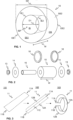
- FIG. 1 illustrates schematically a coil or roll (hereinafter “coil") 10 in accordance with an embodiment of the present invention.
- the coil 10 may be, for example, a metal coil or roll, such as of stainless steel.
- the coil 10 may, alternatively, be a paper roll (or coil).
- the coil 10, preferably, includes an outer surface OS, an inner surface IS, and two side surfaces SS1, SS2.
- the inner surface IS defines an inner space ISP of the coil 10.
- Inner edges of the side surfaces SS1, SS2 have an inner diameter or diameters D1.
- the coil 10 comprises an inner edge or edges IE1, IE2 defined by side end(s) of the inner surface IS.
- the coil 10 comprises an outer edge or edges OE1, OE2 defined by side ends of the outer surface OS.
- the coil 10 has a width Wand an outer diameter D2 as shown in Fig. 1 .
- the coil 10 may, for example, have dimensions such as follows: the width W 1200 mm, the outer diameter D2 1200 mm or the like. However, coils 10 of various sizes may be protected by utilizing an embodiment in accordance with the present invention.
- the width W may be in the range from 200 mm to 4000 mm, and the outer diameter D2 in the range from 500 mm to 2000 mm, for instance.
- FIG. 2 illustrates schematically a coil 10 and coil 10 packaging material in accordance with an embodiment of the present invention.
- the coil 10 packaging material may include an outer edge protector 18 or protectors 18, such as of plastic material.
- the outer edge protector(s) 18 protect the plastic film and/or paper sheet material used to provide protection against corrosion from tearing when being wound through the inner space ISP of the coil 10 and around the coil 10.
- the coil 10 may further be protected by using mechanical protecting elements, such as metal, plastic, paper, hardboard, and/or cardboard film or sheet.
- mechanical protecting elements such as metal, plastic, paper, hardboard, and/or cardboard film or sheet.
- an outer mechanical protecting element arranged on the outer surface OS of the coil 10 (not shown in Fig. 2 ).
- inner mechanical protecting elements such as inner body material 16, and/or side protecting elements, such as headers or side covers 14, arranged on the inner IS and side surface(s) SS1, SS2 of the coil 10, respectively.
- the coil 10 packaging material may, preferably, include one or two inner edge protectors 13 to be arranged to protect the inner edge(s) IE1, IE2 of the coil 10.
- the inner edge protectors 13 may, preferably, be of metal, such as steel.
- the packaging may also include arranging band strips of metal (not shown) around the coil 10 through the inner space ISP. There may also be band strips (not shown) arranged around the outer surface OS of the coil 10. The band strips then tightly hold the package material covering the coil 10.
- the packaged coil 10 may further be provided with identification information, such as labels, tags, etc.
- FIG. 3 illustrates schematically an inner edge protecting element 11 according to an embodiment of the present invention.
- the inner edge protecting element 11 comprises a first end 11A and a second end 11B.
- the ends 11A, 11B are opposite ends with respect to each other in a longitudinal direction of the inner edge protecting element 11.
- Fig. 3 illustrates at 101 an inner edge protecting element 11, such as a planar metal sheet or strip.
- an inner edge protecting element 11 is shown which includes a bend 11C in the longitudinal direction of the element 11.
- the bend 11C may define two portions, that is the first 12A and the second 12B portion, of the element 11.
- the inner edge protecting elements 11 shown at 101 and 102 are optional and may merely show two stages of producing the inner edge protecting element 11. This is illustrated by the arrows between the stages pointing from left to right.
- at 103 is shown a preferable embodiment of the inner edge protecting element 11.
- the inner edge protecting element 11 has been arranged to conform or to have a corresponding shape with respect to the shape of the inner edge IE1, IE2 of the coil 10.
- Figure 4 illustrates schematically an inner edge protector 13 according to an embodiment of the present invention.
- Fig. 4 illustrates, at 111, an inner edge protecting element 11 according to an embodiment having two portions 12C, 12D to be arranged overlapped with respect to each other as shown at 112.
- the inner edge protecting element 11 has substantially a closed shape having a first diameter D, such as defined by the first portion 12A of the inner edge protecting element 11.
- Fig. 4 illustrates, at 113, the inner edge protector 13.
- the inner edge protector 13 has been provided by mechanically securing at the overlapping portions 12C, 12D of the inner edge protecting element 11 by, for example, welding, such as spot welding, or riveting the overlapping portions to each other at position 13A.
- the overlapping portions may be coupled or secured by a nut and bolt, or by other mechanical securing means.
- the securing may alternatively or in addition be performed at position 13B, for instance.
- the securing device 30 may comprise a puncher or punching device.
- the mechanical securing may, thus, be implemented by punching at the two overlapping portions such that the penetration of the punch through the portions or at least causing deformation of the portions, if not penetrated through, provide the mechanical securing when the two portions stick to each other due to the deformation at the corresponding positions relative to each other.
- the securing device 30 may comprise a cutting or a bending device.
- the mechanical securing may, thus, be implemented by cutting or bending the inner edge protecting element at the overlapping portions such that the portions become attached to each other. This may be done, for example, at the outer edge of the inner edge protecting element, such as at the second portion thereof.
- the inner edge protecting element 11 may comprise at the overlapping portions a ratcheting mechanism, such as having a protrusion or protrusions in one of the overlapping portions, and a hole or cavity or holes or cavities in the other one of the overlapping portions at corresponding positions.
- the protrusion(s) and the hole(s) may, advantageously, be arranged such that when coupled to each other, the inner edge protecting element 11 locks, or mechanically secures, into the desired position to protect the inner edge IE1, IE2, and thus forms the inner edge protector 13.
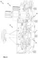
- FIG. 5 illustrates schematically a coil or roll packing arrangement 100 according to an embodiment of the present invention.
- the coil packing arrangement 100 may comprise a coil or roll packing machine 40.
- the coil or roll packing machine 40 may comprise a robot 42 and a securing device 44.
- the robot 42 may be configured at least to arrange a portion, such as the first portion 12A, of an inner edge protecting element 11 into an inner space ISP at an end of an inner surface IS of a coil 10.
- the robot 42 may further be configured to increase the first diameter D so that at least part of the portion, such as the first portion 12A, becomes in contact with the inner surface IS of the coil 10.
- the securing device may be configured at least to mechanically secure the inner edge protecting element 11 to provide an inner edge protector 13 secured into the inner space ISP and arranged along and in contact with an inner edge IE1, IE2 of the coil 10.
- the arrangement 100 may comprise a control unit 150 configured to control the operation of the arrangement 100, such as the arranging of the inner edge protecting element 11 into the inner space ISP of the coil 10.
- the control unit 150 may, preferably, be in communication connection with various devices of the arrangement 100.
- the control unit 150 may comprise one or more processors, one or more memories being volatile or non-volatile for storing portions of computer program code and any data values and possibly one or more user interface units.
- the mentioned elements may be communicatively coupled to each other with e.g. an internal bus.
- the processor of the control unit 150 may at least be configured to implement at least some operational steps as described herein with respect to the arrangement and methods.
- the implementation of the methods may be achieved by arranging the processor to execute at least some portion of computer program code stored in the memory causing the processor, and thus the control unit 150, to implement one or more method steps to be described hereinlater.
- the processor may thus be arranged to access the memory and retrieve and store any information therefrom and thereto.
- the processor herein refers to any unit suitable for processing information and control the operation of the control unit 150, among other tasks.
- the operations may also be implemented with a microcontroller solution with embedded software.
- the memory is not limited to a certain type of memory only, but any memory type suitable for storing the described pieces of information may be applied in the context of the present invention.
- the control unit 150 may comprise a communication interface to which external units may be connected to.
- External unit may comprise wireless connection or a connection by a wired manner.
- the communication interface may provide interface for communication with external units such as the elevator car, the electric motor, the doors of the landing floors, or the electrical drive to the elevator control unit.
- There may also be connecting to the external system, such as a laptop or a handheld device.
- There may also be a connection to a database of the elevator or an external database including information used in controlling the operation of the elevator.
- the coil or roll packing arrangement 100 may comprise a squeezing device 30 configured to reduce the first diameter D to be less than an inner diameter D1 of the coil 10 by pushing the inner edge protecting element 11 from outside with respect to the closed shape.
- the robot 42 may additionally be configured to fetch and grab the inner edge protecting element 11 from the squeezing device 30.
- the squeezing device 30 may further be configured to bend the inner edge protecting element 11 to include two portions 12A, 12B, and to form the edge protecting element 11 to conform or to have a corresponding shape with respect to the shape of the inner edge IE1, IE2 of the coil 10, such as shown at 103 in Fig. 3 .
- the coil or roll packing arrangement 100 may comprise an inner edge protecting element manufacturing device 20.
- the inner edge protecting element manufacturing device 20 may be configured to manufacture an inner edge protecting element 11 such as shown at 101 in Fig. 3 , such as, a planar metal sheet or strip.
- the inner edge protecting element manufacturing device 20 may also be arranged to provide the inner edge protecting element 11 to the squeezing device 30.
- the robot 42 may be further configured to fetch a header 14 from a header storage 60.
- the header 14 may be configured to be fetch such that it is arranged around the inner edge protecting element 11 held by the robot 42. Therefore, the inner edge protecting element 11 and the header 14 may be substantially simultaneously arranged on the coil 10.
- the coil or roll packing arrangement 100 may comprise an adhesion machine 50.
- the adhesion machine 50 may comprise an adhesion head 52 and a main unit 51, such as including the adhesive.
- the robot 42 may be further configured to move the header 14 in contact with the adhesion head 52 for applying adhesive on the header 14.
- the header 14 may, thus, be adhered to the side surface SS1, SS2 of the coil 10.
- the inner edge protecting element manufacturing device 20 may further be arranged to form the planar inner edge protecting element 11 to substantially conform or to have a corresponding shape with respect to the shape of the inner edge IE1, IE2 of the coil 10 prior to being bend. This is shown in Fig. 5 in which the planar strip has a spiral-like shape at the inner edge protecting element manufacturing device 20.
- the inner edge protecting element manufacturing device 20 may further be configured to cut the inner edge protecting element 11 to desired length.
- Figure 6 illustrates schematically a coil or roll packing arrangement 40 according to an embodiment of the present invention.
- the coil or roll packing machine 40 may be configured to fetch the inner edge protecting element 11 from the squeezing device 30.
- FIG. 7 illustrates schematically a coil or roll packing machine 40 according to an embodiment of the present invention.
- the robot 42 may comprise spreading elements 46, and the robot 42 may be configured to increase the first diameter D of the inner edge protecting element 11 by pushing the inner edge protecting element 11 at a plurality of different positions towards the inner surface IS (not shown in Fig. 6 ) by the spreading elements 46.
- the robot may also comprise gripping elements 48, such as claws.
- the spreading elements 46 may be elastic or comprise elastic coupling with respect to the robot 42, such as by a spring or spring-like element.
- the coil or roll packing machine 40 may also comprise a securing device 44, such as a welding, preferably a spot welding, machine.
- the inner edge protecting element 11 may be gripped by the gripping elements 48, such as claws, comprised in the robot 42.
- the gripping elements 48 may be configured to support the inner edge protecting element 11 during moving of the element and maintaining the inner edge protecting element 11 in its adapted shape, such as, having a smaller first diameter D than the inner diameter D1 of the coil 10.
- Figure 8 illustrates schematically a coil or roll packing machine 40 of Fig. 7 by a cutaway view.
- Figure 9 illustrates schematically a coil or roll packing machine 40 by a cross-sectional view according to an embodiment of the present invention.
- the coil or roll packing machine 40 may be configured to arrange at least a portion of the adapted inner edge protecting element 11, that is having smaller diameter than the inner diameter D1 of the coil 10, into the inner space ISP at the end of the inner surface IS.
- the adapted inner edge protecting element 11 is not be arranged into the inner space ISP completely in order have space for one of the electrodes 49 of the welding machine between the machine 40 and the coil 10.
- a part of the adapted inner edge protecting element 11, that is the part including the overlapping portions 12C, 12D, may be arranged between the electrodes 49 for mechanical securing after increasing, by the coil or roll packing machine 40, particularly the spreading elements 46 thereof, the first diameter D so that at least part of said portion, such as the first portion 12A, of the adapted inner edge protecting 11 in the inner space ISP becomes in contact with the inner surface IS.
- Fig. 10 which illustrates schematically a coil or roll packing machine by a cross-sectional view according to an embodiment of the present invention, the inner edge protecting element 11 has been shown with increased diameter D so as to become in contact with the inner surface IS.
- the coil or roll packing machine 40 is configured to maintain the force used to increase the first diameter D during the securing. This further improves the coupling between the inner edge protector 13 and the inner surface IS of the coil 10.
- the inner edge protecting element 11 is an inner edge protector 13 being secured into the inner space ISP and arranged along and in contact with the inner edge IE1, IE2.
- Said portion inner edge protector 13, such as the first portion 12A, may then, after the securing device 44 has been removed, pushed completely into the inner space ISP.
- the second portion 12B may then become in contact with the side surface SS1, SS2 of the coil 10.
- Figure 11 illustrates schematically a coil or roll packing machine 40 by a cutaway view according to an embodiment of the present invention.
- the mechanisms for moving the spreading elements 46 according to some embodiments are shown.
- the mechanisms may utilize, for example, hydraulics for moving the spreading elements 46.
- Fig. 11 illustrates pushing elements 47 arranged to push the inner edge protector 13 into the inner space ISP.
- pushing elements 47 may be plurality of pushing elements 47 in the coil or roll packing machine 40.
- the securing device 44 also includes a pushing element 47.
- the first diameter D of the inner edge protecting element 11 may be configured to be increased such that the inner body packaging material 16 becomes trapped between the inner edge protecting element 11 and the inner surface IS of the coil 10.
- Figure 12 illustrates schematically a coil or roll packing machine 40 of Fig. 11 from a perspective.
- the inner edge protector 13 has been provided after increasing its diameter by the robot 42 and securing it by the securing device 44.
- Figure 13 illustrates schematically a coil or roll packing machine 40 according to an embodiment of the present invention.
- the coil or roll packing machine 40 has been arranged to insert the inner edge protector 13 into the inner space ISP of the coil 10.
- FIG 14 illustrates schematically a securing device 44 according to an embodiment of the present invention.
- Figure 15 illustrates schematically the securing device 44 of Fig. 14 by a cross-sectional view.
- the securing device 44 in Figs. 14 and 15 is a spot welding device.
- the spot welding device may comprise hydraulics means, such as including hydraulic cylinders 81 for moving the electrodes and pushing element 47 towards the coil 10 when inserting the inner edge protecting element 11 and/or the inner edge protector 13 into the inner space ISP.
- the securing device 44 may comprise powering means 83 for providing electrical power or hydraulic oil, for instance.
- Figure 16 illustrates schematically a coil or roll packing system 300 according to an embodiment of the present invention.
- the coil packing system 300 may, preferably, be at least partly automatic or even fully automatic.
- a coil or roll packing system 300 may comprise at least one or a plurality of stations 200-205. At least one 200 of the stations 200-205 may, preferably, comprise a coil or roll packing arrangement 100 according to some embodiment of the present invention, for example, as shown in Fig. 5 .
- stations 200, 204 there may be at least two stations 200, 204.
- Other one 204 of the stations may comprise an inner body machine which is configured to arranged inner body packaging material 16 into the inner space ISP of the coil 10 defined by the inner surface IS.
- the plurality of station 200-205 may be connected to each other by a coil car track 215.
- the track 215 may, preferably, extend through the plurality of stations 200-205 such that the coil or roll 10 may be moved through all of the stations 200-205 by the coil car 210, preferably, in automated or at least remote controlled manner.
- the plurality of stations 200-205 may include, for example, in the first station 201, an entry sand and a measuring gate. In the entry sand and measuring gate, the coil 10 may be measured, such as its weight and dimensions.
- the second station 202 may include a plastic inner surface protecting machine in which a plastic inner surface protector may be arranged onto the inner surface IS.
- the third station 203 may comprise an eye wrapper machine which provides protective layer against corrosion such as by winding the material through the inner space ISP. This may include using plastic and paper sheet or films.
- the outer edge OE1, OE2 of the coil 10 may be protected by a edge protector 18, such as of plastic.
- mechanical protectors may be arranged onto the outer surface OS of the coil 10.
- system 300 may comprise the station including the arrangement 100 according to some embodiment of the present invention as described hereinbefore.
- system 300 may comprise, at the fifth station 205, a bodystrap-per machine which may provide band strips through the inner space IS and around the coil 10, and/or around the outer surface OS.
- the system 300 may further comprise stations in which packaging material is provided to protect the coil 10. These may be such as known to a person skilled in the art.
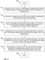
- Figure 17 illustrates a flow diagram of a method according to an embodiment of the present invention. The method may be implemented by utilizing the control unit 150 and/or the arrangements 100, such as the devices and/or machines, described hereinbefore.
- Item 1000 in Fig. 16 may refer to a start-up phase of the method. Suitable equipment, devices, and/or machines, such as a coil or roll packing machine, and components and subsystems are obtained, and systems assembled and configured for operation.
- Suitable equipment, devices, and/or machines such as a coil or roll packing machine, and components and subsystems are obtained, and systems assembled and configured for operation.
- Item 1010 may refer to providing the coil 10 comprising an inner edge IE1, IE2 defined by an inner surface IS of the coil 10, wherein the inner edge IE1, IE2 defines an inner diameter D1 of the coil 10 and the inner surface IS defines an inner space ISP of the coil 10.
- Item 1020 may refer to providing an inner edge protecting element 11 comprising a first end 11A and a second end 11B, wherein said ends are opposite ends with respect to each other in a longitudinal direction of the inner edge protecting element 11.
- the inner edge protecting element 11 may include at least two portions 12A, 12B, the first portion and the second portion, separated by a bend 11C in a longitudinal direction of the element 11.
- the inner edge protecting element 11 may have a cross-section having L-shape or the like, in case of a right angle at the bend 11C.
- the angle may differ from the right angle, however, be in the range of 60 to 120 degrees, advantageously 70 to 110 degrees or more advantageously 80 to 100 degrees, or the even more advantageously 85 to 95 degrees.
- the cross-section of the first portion 12A of the inner edge protecting element 11 may, preferably, be straight in order to conform with the inner surface IS of the coil 10 when being arranged in contact with the inner surface IS.
- the shape of the cross-section of the second portion 12B may vary.
- the method may comprise arranging the inner edge protecting element 11 to a squeezing device 30 and reducing the first diameter D to be less than the inner diameter D1 by the squeezing device 30 by pushing the inner edge protecting element 11 from outside with respect to the closed shape.
- the method may comprise gripping the inner edge protecting element 11 by gripping elements 48, such as claws, comprised in the coil or roll packing machine 40, wherein the gripping elements 48 may be configured to support the inner edge protecting element 11 during moving of the element 11.
- gripping elements 48 such as claws
- Item 1030 may refer to adapting the inner edge protecting element 11 to overlap at two portions 12C, 12D of the inner edge protecting element 11, thereby forming substantially a closed shape having a first diameter D.
- the method may comprise arranging the first diameter D to be less than the inner diameter D1 so that the portion, such as the first portion 12A, of the inner edge protecting element 11 fits into the inner space ISP.
- the method may comprise arranging the two portions 12C, 12D of the inner edge protecting element 11 to a first position in the squeezing device 30. Furthermore, the method may comprise gripping the inner edge protecting element 11 by the gripping elements 48 comprised in the coil or roll packing machine 40 such that the first position corresponds to a position of the securing device 44.
- Item 1040 may refer to arranging, by a coil or roll packing machine 40, a portion, such as the first portion 12A, of the adapted inner edge protecting element 11 into the inner space ISP at the end of the inner surface IS.
- the portion of the adapted inner edge protecting element 11 arranged into the inner space ISP may be the first portion 12A in which case the second portion 12B may become in contact with a side surface SS1, Ss2 of the coil 10.
- Item 1050 may refer to increasing, by the coil or roll packing machine 40, the first diameter D so that at least part of the portion, such as the first portion 12A, of the adapted inner edge protecting 11 becomes in contact with the inner surface IS.
- the increasing of the first diameter D may comprise pushing the inner edge protecting element 11 at a plurality of different positions towards the inner surface IS by spreading elements 46 comprised in the coil or roll packing machine 40, such as in the robot 42.
- the method may comprise maintaining by the coil or roll packing machine 40 the force used to increase the first diameter D during securing 1060. This further improves the coupling between the inner edge protector 13 and the inner surface IS of the coil 10.
- Item 1060 may refer to mechanically securing, by the coil or roll packing machine 40, the inner edge protecting element 11 at the two portions 12C, 12D to provide an inner edge protector 13 secured into the inner space IS and arranged along and in contact with the inner edge IE1, IE2.
- the securing device 44 may comprise a welding device, such as a spot welding device.
- the method may comprise welding, such as spot welding, by the welding device, the two portions 12C, 12D of the inner edge protecting element 11 to each other, thereby mechanically securing the inner edge protecting element 11.
- the securing device 44 may comprise a riveting device.
- the method may comprise securing, by the riveting device, the two portions 12C, 12D of the inner edge protecting element 11 to each other, thereby mechanically securing the inner edge protecting element 11.
- the method may comprise, after the mechanical securing 1060, pushing, by the coil or roll packing machine 40, the inner edge protector 13 to be in contact with a side surface SS1, SS2 of the coil 10.
- the method may comprise arranging a header 14 around the adapted inner edge protecting element 11 and arranging the header 14 onto a side surface SS1, SS2 of the coil 10.
- the inner edge protector 13 has been arranged to protect the inner edge IE1, IE2 of the coil 10.
Landscapes
- Engineering & Computer Science (AREA)
- Mechanical Engineering (AREA)
- Packaging Of Machine Parts And Wound Products (AREA)
- Basic Packing Technique (AREA)
Description
- The present invention relates in general to methods, arrangements and systems for packing coils or rolls, such as metal coils or paper rolls. In particular, however not exclusively, the present invention concerns methods, arrangements and systems for providing protection for the inner edge of the coil or roll.
- There are some known methods for packing metal coils which utilize different packaging material layers to protect the metal coil from outside moisture and dust. Generally, metal coils are packed in order to be protected from the environment when being transported, for example, by a vehicle, ship, or the like.
- Packaging of metal coils can include, for example, arranging waterproof vinyl, moisture absorbing paper and a scratch-resistant thin metal foil to protect the coil. It is known to provide packaging material on both the outer surface of the coils as well as on the inner surface of the coil.
- In known solutions, the packing of the coil is performed by operators who arrange the different packaging materials on the coil. Furthermore, different parts of the packaging, such as the inner edge protector, are typically manually attached to the coil by using adhesive, such as adhesive tape, glue or silicone. The packing thus requires much manual labor which causes high costs. Furthermore, utilization of adhesives is undesirable in the packaging due to unwanted health related issues, such as the adhesives being toxic. Furthermore, adhesives tend to be messy. The adhesives also cause the packaging to become hard to unpack because the packaging material has been attached to the coil by the adhesive.
- Document
AU 2008221599 A1 - Document
KR 20180051769 A - Document
JP H07291218 A - Document
KR 20100110184 A - An objective of the present invention is to provide a method for packing a coil or roll, a coil or roll packing arrangement, and a coil or roll packing system. Another objective of the present invention is that the method, the arrangement, and the system at least alleviate some of drawbacks in the known solutions, such as related to the utilization of manual labor and adhesives.
- The objectives of the invention are reached by a method for packing a coil or roll, a coil or roll packing arrangement, and a coil or roll packing system as defined by the respective independent claims.
- According to a first aspect of the present invention, a method for packing a coil or roll is provided.
- The method comprises:
- providing the coil or roll comprising an inner edge defined by an inner surface of the coil or roll, wherein the inner edge defines an inner diameter of the coil or roll and the inner surface defines an inner space (or an eye or a hole or a through-hole or an inner volume) of the coil or roll,
- providing an inner edge protecting element comprising a first end and a second end, wherein said ends are opposite ends with respect to each other in a longitudinal direction of the inner edge protecting element,
- adapting the inner edge protecting element to overlap at two portions of the inner edge protecting element, thereby forming substantially a closed shape having a first diameter,
- arranging, by a coil or roll packing machine, a portion of the adapted inner edge protecting element into the inner space at the end of the inner surface,
- increasing, by the coil or roll packing machine, the first diameter so that at least part of the portion becomes in contact with the inner surface, and
- mechanically securing, by the coil or roll packing machine, the inner edge protecting element at the two portions to provide an inner edge protector secured into the inner space and arranged along and in contact with the inner edge, wherein the mechanically securing comprises attaching the two portions to each other by the coil or roll packing machine, thereby, preferably, fixing the increased first diameter.
- The coil or roll may, preferably, be a metal coil, for example, of steel or aluminum. Alternatively, the coil or roll may be a paper roll.
- In various embodiments, the method may comprise maintaining by the coil or roll packing machine the force used to increase the first diameter during the securing. This further improves the coupling between the inner edge protector and the inner surface of the coil or roll.
- In various embodiments, the inner edge protecting element may include at least two portions, the first portion and the second portion, separated by a bend in a longitudinal direction of the element. Thus, the inner edge protecting element may have a cross-section having L-shape or the like, in case of a right angle at the bend. The angle may differ from the right angle, however, be in the range of 60 to 120 degrees, advantageously 70 to 110 degrees or more advantageously 80 to 100 degrees, or the even more advantageously 85 to 95 degrees.
- In some embodiments, the cross-section of the first portion of the inner edge protecting element may, preferably, be straight in order to conform with the inner surface of the coil or roll when being arranged in contact with the inner surface. However, the shape of the cross-section of the second portion may vary.
- In various embodiments, the portion of the adapted inner edge protecting element arranged into the inner space may be the first portion in which case the second portion may become in contact with a side surface of the coil or roll.
- In various embodiments, the method may comprise arranging the first diameter to be less than the inner diameter so that the portion of the inner edge protecting element fits into the inner space.
- In various embodiments, a securing device comprised in the coil or roll packing machine may comprise a welding device, such as a spot welding device. In these embodiments, the method may comprise welding, such as spot welding, by the welding device, the two portions of the inner edge protecting element to each other, thereby mechanically securing the inner edge protecting element.
- In various embodiments, the securing device may comprise a riveting device. In these embodiments, the method may comprise securing, by the riveting device, the two portions of the inner edge protecting element to each other, thereby mechanically securing the inner edge protecting element.
- In some embodiments, the securing device may comprise a puncher or punching device. The mechanical securing may, thus, be implemented by punching at the two overlapping portions such that the penetration of the punch through the portions or at least causing deformation of the portions, if not penetrated through, provide the mechanical securing when the two portions stick to each other due to the deformation at the corresponding positions relative to each other.
- In some embodiments, the securing device may comprise a cutting or a bending device. The mechanical securing may, thus, be implemented by cutting or bending the inner edge protecting element at the overlapping portions such that the portions become attached to each other. This may be done, for example, at the outer edge of the inner edge protecting element, such as at the second portion thereof.
- In a further embodiment, the inner edge protecting element may comprise at the overlapping portions a ratcheting mechanism, such as having a protrusion or protrusions in one of the overlapping portions, and a hole or cavity or holes or cavities in the other one of the overlapping portions at corresponding positions. The protrusion(s) and the hole(s) may, advantageously, be arranged such that when coupled to each other, the inner edge protecting element locks, or mechanically secures, into the desired position to protect the inner edge, and thus forms the inner edge protector.
- In some embodiments, the method may comprise gripping the inner edge protecting element by gripping elements, such as claws, comprised in the coil or roll packing machine, wherein the gripping elements may be configured to support the inner edge protecting element during moving of the element.
- In various embodiments, the increasing of the first diameter may comprise pushing the inner edge protecting element at a plurality of different positions towards the inner surface by spreading elements comprised in the coil or roll packing machine.
- In various embodiments, the method may comprise arranging the inner edge protecting element to a squeezing device and reducing the first diameter to be less than the inner diameter by the squeezing device by pushing the inner edge protecting element from outside with respect to the closed shape.
- In various embodiments, the method may comprise arranging the two portions of the inner edge protecting element to a first position in the squeezing device. Furthermore, the method may comprise gripping the inner edge protecting element by the gripping elements comprised in the coil or roll packing machine such that the first position corresponds to a position of the securing device.
- In some embodiments, the method may comprise, after the mechanical securing, pushing, by the coil or roll packing machine, the inner edge protector to be in contact with a side surface of the coil or roll.
- In various embodiments, the method may comprise arranging a header or a side cover around the adapted inner edge protecting element and arranging the header or the side cover onto a side surface of the coil or roll.
- According to a second aspect of the present invention, a coil or roll packing arrangement is provided.
- The coil or roll packing arrangement comprises a coil or roll packing machine comprising a robot or manipulator and a securing device, wherein the robot or manipulator is configured to arrange a portion of an inner edge protecting element into an inner space at an end of an inner surface of a coil or roll, wherein the inner edge protecting element comprises two overlapping portions, thereby forming substantially a closed shape having a first diameter, to increase the first diameter so that at least part of the portion becomes in contact with the inner surface. The securing device is configured to mechanically secure the inner edge protecting element at the two overlapping portions to provide an inner edge protector secured into the inner space and arranged along and in contact with an inner edge of the coil or roll, wherein the mechanically securing comprises attaching the two overlapping portions to each other by the coil or roll packing machine, thereby, preferably, fixing the increased first diameter.
- The robot or manipulator may refer to any kind of a device or machine which may be configured, such as programmed, to perform the steps in accordance with the present invention. Thus, the robot or manipulator may be configured to move or being moved in one, two, or three dimensions. Furthermore, with respect to the movement, the robot or manipulator may have any number of degrees of freedom, such as from five to seven, for instance. The robot or manipulator may in some embodiments have one or several robot or manipulating arms.
- In some embodiments, the securing device may be a welding or a riveting device configured to mechanically secure the inner edge protecting element.
- In various embodiments, the coil or roll packing arrangement may comprise a squeezing device configured to reduce the first diameter to be less than an inner diameter of the coil or roll by pushing the inner edge protecting element outside the closed shape.
- In various embodiments, the robot may comprise spreading elements, such as plugs or pegs, and the robot may be configured to increase the first diameter by pushing the inner edge protecting element at a plurality of different positions towards the inner surface by the spreading elements.
- In one preferable embodiment, the spreading elements may be elastic or comprise elastic coupling with respect to the robot, such as by a spring or spring-like element.
- According to a third aspect of the present invention, a coil or roll packing system is provided.
- The coil or roll packing system comprises a plurality of stations, wherein at least one of the stations comprise a coil or roll packing arrangement according to the second aspect or any embodiment thereof.
- In some embodiments, other one of the plurality of stations may comprise providing other packaging material to the coil or roll, such as providing packaging material for protecting the coil against corrosion. This may include utilizing plastic and/or paper packaging material arranged on the surfaces of the coil, such as on the outer and the inner surfaces.
- In various embodiments, the coil or roll may be arranged to be moved by a coil car along a coil car track. The track may, preferably, extend through the plurality of stations such that the coil or roll may be moved through all of the stations by the coil car, preferably, in automated or at least remote controlled manner.
- The present invention provides a method for packing a coil or roll, a coil or roll packing arrangement, and a coil or roll packing system. The present invention provides advantages over known solutions in that the inner edge protector may be provided to the coil or roll without need to use adhesives, such as glue or silicone. In known solutions, having pre-manufactured inner edge protectors which are pushed by force into the inner space of the coil or roll, the protectors tend to fall off from the inner space due to having elastic energy stored in them due to being constricted when pushed by force into the inner space. In the present invention, the inner space protecting element has been, on the contrary, expanded against the inner surface of the coil or roll to form the inner edge protector, thus the elastic energy is minimized. The present invention has the advantage that the diameter of the inner edge protecting element, and therefore of the inner edge protector, can be adjusted in stepless manner or at least practically continuously. The invention also allows providing an automatic coil or roll packing arrangement in which the provision of the inner edge protector to the coil or roll does not require manual work from the operator. Furthermore, the coil or roll packing arrangement and/or the equipment, such as the machines and/or the devices, thereof may form part of the coil or roll packing system which, thus, can be fully automated or at least automated with respect to the station including the equipment configured to provide the inner edge protector to the coil or roll.
- Various other advantages will become clear to a skilled person based on the following detailed description.
- The expression "a number of" may herein refer to any positive integer starting from one (1).
- The expression "a plurality of" may refer to any positive integer starting from two (2), respectively.
- The terms "first" and "second" are herein used to distinguish one element from other element, and not to specially prioritize or order them, if not otherwise explicitly stated.
- The exemplary embodiments of the present invention presented herein are not to be interpreted to pose limitations to the applicability of the appended claims. The verb "to comprise" is used herein as an open limitation that does not exclude the existence of also unrecited features. The features recited in depending claims are mutually freely combinable unless otherwise explicitly stated.
- The novel features which are considered as characteristic of the present invention are set forth in particular in the appended claims. The present invention itself, however, both as to its construction and its method of operation, together with additional objectives and advantages thereof, will be best understood from the following description of specific embodiments when read in connection with the accompanying drawings.
- Some embodiments of the invention are illustrated by way of example, and not by way of limitation, in the figures of the accompanying drawings.
-
Figure 1 illustrates schematically a coil or roll in accordance with an embodiment of the present invention. -
Figure 2 illustrates schematically a coil or roll and coil packaging material in accordance with an embodiment of the present invention. -
Figure 3 illustrates schematically an inner edge protecting element according to an embodiment of the present invention. -
Figure 4 illustrates schematically an inner edge protector according to an embodiment of the present invention. -
Figure 5 illustrates schematically a coil or roll packing arrangement according to an embodiment of the present invention. -
Figure 6 illustrates schematically a coil or roll packing arrangement according to an embodiment of the present invention. -
Figure 7 illustrates schematically a coil or roll packing machine according to an embodiment of the present invention. -
Figure 8 illustrates schematically a coil or roll packing machine ofFig. 7 by a cutaway view. -
Figure 9 illustrates schematically a coil or roll packing machine by a cross-sectional view according to an embodiment of the present invention. -
Figure 10 illustrates schematically a coil or roll packing machine by a cross-sectional view according to an embodiment of the present invention. -
Figure 11 illustrates schematically a coil or roll packing machine by a cutaway view according to an embodiment of the present invention. -
Figure 12 illustrates schematically a coil or roll packing machine ofFig. 11 from a perspective. -
Figure 13 illustrates schematically a coil or roll packing machine according to an embodiment of the present invention. -
Figure 14 illustrates schematically a securing device according to an embodiment of the present invention. -
Figure 15 illustrates schematically the securing device ofFig. 14 by a cross-sectional view. -
Figure 16 illustrates schematically a coil or roll packing system according to an embodiment of the present invention. -
Figure 17 illustrates a flow diagram of a method according to an embodiment of the present invention. -
Figure 1 illustrates schematically a coil or roll (hereinafter "coil") 10 in accordance with an embodiment of the present invention. Thecoil 10 may be, for example, a metal coil or roll, such as of stainless steel. Thecoil 10 may, alternatively, be a paper roll (or coil). As shown inFig. 1 , thecoil 10, preferably, includes an outer surface OS, an inner surface IS, and two side surfaces SS1, SS2. Furthermore, the inner surface IS defines an inner space ISP of thecoil 10. Inner edges of the side surfaces SS1, SS2 have an inner diameter or diameters D1. Furthermore, thecoil 10 comprises an inner edge or edges IE1, IE2 defined by side end(s) of the inner surface IS. Still further, thecoil 10 comprises an outer edge or edges OE1, OE2 defined by side ends of the outer surface OS. - The
coil 10 has a width Wand an outer diameter D2 as shown inFig. 1 . Thecoil 10 may, for example, have dimensions such as follows: the width W 1200 mm, the outer diameter D2 1200 mm or the like. However, coils 10 of various sizes may be protected by utilizing an embodiment in accordance with the present invention. The width W may be in the range from 200 mm to 4000 mm, and the outer diameter D2 in the range from 500 mm to 2000 mm, for instance. -
Figure 2 illustrates schematically acoil 10 andcoil 10 packaging material in accordance with an embodiment of the present invention. Thecoil 10 packaging material may include anouter edge protector 18 orprotectors 18, such as of plastic material. The outer edge protector(s) 18 protect the plastic film and/or paper sheet material used to provide protection against corrosion from tearing when being wound through the inner space ISP of thecoil 10 and around thecoil 10. There may also be arranged further outer edge protector(s), such as preferably of metal, for example, steel, arranged on the outer edge protector(s) after winding the protection material against corrosion. - The
coil 10 may further be protected by using mechanical protecting elements, such as metal, plastic, paper, hardboard, and/or cardboard film or sheet. There may be an outer mechanical protecting element arranged on the outer surface OS of the coil 10 (not shown inFig. 2 ). There may also be inner mechanical protecting elements, such asinner body material 16, and/or side protecting elements, such as headers or side covers 14, arranged on the inner IS and side surface(s) SS1, SS2 of thecoil 10, respectively. - According to various embodiments, such as shown in
Fig. 2 , thecoil 10 packaging material may, preferably, include one or twoinner edge protectors 13 to be arranged to protect the inner edge(s) IE1, IE2 of thecoil 10. Theinner edge protectors 13 may, preferably, be of metal, such as steel. - Finally, the packaging may also include arranging band strips of metal (not shown) around the
coil 10 through the inner space ISP. There may also be band strips (not shown) arranged around the outer surface OS of thecoil 10. The band strips then tightly hold the package material covering thecoil 10. The packagedcoil 10 may further be provided with identification information, such as labels, tags, etc. -
Figure 3 illustrates schematically an inneredge protecting element 11 according to an embodiment of the present invention. The inneredge protecting element 11 comprises afirst end 11A and asecond end 11B. The ends 11A, 11B are opposite ends with respect to each other in a longitudinal direction of the inneredge protecting element 11. -
Fig. 3 illustrates at 101 an inneredge protecting element 11, such as a planar metal sheet or strip. At 102, an inneredge protecting element 11 is shown which includes abend 11C in the longitudinal direction of theelement 11. Thebend 11C may define two portions, that is the first 12A and the second 12B portion, of theelement 11. The inneredge protecting elements 11 shown at 101 and 102 are optional and may merely show two stages of producing the inneredge protecting element 11. This is illustrated by the arrows between the stages pointing from left to right. However, at 103 is shown a preferable embodiment of the inneredge protecting element 11. As can be seen, the inneredge protecting element 11 has been arranged to conform or to have a corresponding shape with respect to the shape of the inner edge IE1, IE2 of thecoil 10. -
Figure 4 illustrates schematically aninner edge protector 13 according to an embodiment of the present invention.Fig. 4 illustrates, at 111, an inneredge protecting element 11 according to an embodiment having twoportions edge protecting element 11 has substantially a closed shape having a first diameter D, such as defined by thefirst portion 12A of the inneredge protecting element 11. Furthermore,Fig. 4 illustrates, at 113, theinner edge protector 13. Theinner edge protector 13 has been provided by mechanically securing at the overlappingportions edge protecting element 11 by, for example, welding, such as spot welding, or riveting the overlapping portions to each other atposition 13A. However, instead of riveting, the overlapping portions may be coupled or secured by a nut and bolt, or by other mechanical securing means. Furthermore, instead of welding at theposition 13A, the securing may alternatively or in addition be performed atposition 13B, for instance. - In some embodiments, the securing
device 30 may comprise a puncher or punching device. The mechanical securing may, thus, be implemented by punching at the two overlapping portions such that the penetration of the punch through the portions or at least causing deformation of the portions, if not penetrated through, provide the mechanical securing when the two portions stick to each other due to the deformation at the corresponding positions relative to each other. - In some embodiments, the securing
device 30 may comprise a cutting or a bending device. The mechanical securing may, thus, be implemented by cutting or bending the inner edge protecting element at the overlapping portions such that the portions become attached to each other. This may be done, for example, at the outer edge of the inner edge protecting element, such as at the second portion thereof. - In a further embodiment, the inner
edge protecting element 11 may comprise at the overlapping portions a ratcheting mechanism, such as having a protrusion or protrusions in one of the overlapping portions, and a hole or cavity or holes or cavities in the other one of the overlapping portions at corresponding positions. The protrusion(s) and the hole(s) may, advantageously, be arranged such that when coupled to each other, the inneredge protecting element 11 locks, or mechanically secures, into the desired position to protect the inner edge IE1, IE2, and thus forms theinner edge protector 13. -
Figure 5 illustrates schematically a coil orroll packing arrangement 100 according to an embodiment of the present invention. Thecoil packing arrangement 100 may comprise a coil orroll packing machine 40. The coil orroll packing machine 40 may comprise arobot 42 and a securingdevice 44. Therobot 42 may be configured at least to arrange a portion, such as thefirst portion 12A, of an inneredge protecting element 11 into an inner space ISP at an end of an inner surface IS of acoil 10. Therobot 42 may further be configured to increase the first diameter D so that at least part of the portion, such as thefirst portion 12A, becomes in contact with the inner surface IS of thecoil 10. Furthermore, the securing device may be configured at least to mechanically secure the inneredge protecting element 11 to provide aninner edge protector 13 secured into the inner space ISP and arranged along and in contact with an inner edge IE1, IE2 of thecoil 10. - Furthermore, the
arrangement 100 may comprise acontrol unit 150 configured to control the operation of thearrangement 100, such as the arranging of the inneredge protecting element 11 into the inner space ISP of thecoil 10. Thecontrol unit 150 may, preferably, be in communication connection with various devices of thearrangement 100. - The
control unit 150 may comprise one or more processors, one or more memories being volatile or non-volatile for storing portions of computer program code and any data values and possibly one or more user interface units. The mentioned elements may be communicatively coupled to each other with e.g. an internal bus. - The processor of the
control unit 150 may at least be configured to implement at least some operational steps as described herein with respect to the arrangement and methods. The implementation of the methods may be achieved by arranging the processor to execute at least some portion of computer program code stored in the memory causing the processor, and thus thecontrol unit 150, to implement one or more method steps to be described hereinlater. The processor may thus be arranged to access the memory and retrieve and store any information therefrom and thereto. For sake of clarity, the processor herein refers to any unit suitable for processing information and control the operation of thecontrol unit 150, among other tasks. The operations may also be implemented with a microcontroller solution with embedded software. Similarly, the memory is not limited to a certain type of memory only, but any memory type suitable for storing the described pieces of information may be applied in the context of the present invention. - The
control unit 150 may comprise a communication interface to which external units may be connected to. External unit may comprise wireless connection or a connection by a wired manner. The communication interface may provide interface for communication with external units such as the elevator car, the electric motor, the doors of the landing floors, or the electrical drive to the elevator control unit. There may also be connecting to the external system, such as a laptop or a handheld device. There may also be a connection to a database of the elevator or an external database including information used in controlling the operation of the elevator. - Optionally, the coil or
roll packing arrangement 100 may comprise a squeezingdevice 30 configured to reduce the first diameter D to be less than an inner diameter D1 of thecoil 10 by pushing the inneredge protecting element 11 from outside with respect to the closed shape. Therobot 42 may additionally be configured to fetch and grab the inneredge protecting element 11 from the squeezingdevice 30. The squeezingdevice 30 may further be configured to bend the inneredge protecting element 11 to include twoportions edge protecting element 11 to conform or to have a corresponding shape with respect to the shape of the inner edge IE1, IE2 of thecoil 10, such as shown at 103 inFig. 3 . - Optionally, the coil or
roll packing arrangement 100 may comprise an inner edge protectingelement manufacturing device 20. The inner edge protectingelement manufacturing device 20 may be configured to manufacture an inneredge protecting element 11 such as shown at 101 inFig. 3 , such as, a planar metal sheet or strip. The inner edge protectingelement manufacturing device 20 may also be arranged to provide the inneredge protecting element 11 to the squeezingdevice 30. - In some embodiments, the
robot 42 may be further configured to fetch aheader 14 from aheader storage 60. Theheader 14 may be configured to be fetch such that it is arranged around the inneredge protecting element 11 held by therobot 42. Therefore, the inneredge protecting element 11 and theheader 14 may be substantially simultaneously arranged on thecoil 10. - Optionally, the coil or
roll packing arrangement 100 may comprise anadhesion machine 50. Theadhesion machine 50 may comprise anadhesion head 52 and amain unit 51, such as including the adhesive. Therobot 42 may be further configured to move theheader 14 in contact with theadhesion head 52 for applying adhesive on theheader 14. Theheader 14 may, thus, be adhered to the side surface SS1, SS2 of thecoil 10. - The inner edge protecting
element manufacturing device 20 may further be arranged to form the planar inneredge protecting element 11 to substantially conform or to have a corresponding shape with respect to the shape of the inner edge IE1, IE2 of thecoil 10 prior to being bend. This is shown inFig. 5 in which the planar strip has a spiral-like shape at the inner edge protectingelement manufacturing device 20. The inner edge protectingelement manufacturing device 20 may further be configured to cut the inneredge protecting element 11 to desired length. -
Figure 6 illustrates schematically a coil or roll packingarrangement 40 according to an embodiment of the present invention. As can be seen, the coil orroll packing machine 40 may be configured to fetch the inneredge protecting element 11 from the squeezingdevice 30. -
Figure 7 illustrates schematically a coil orroll packing machine 40 according to an embodiment of the present invention. Therobot 42 may comprise spreadingelements 46, and therobot 42 may be configured to increase the first diameter D of the inneredge protecting element 11 by pushing the inneredge protecting element 11 at a plurality of different positions towards the inner surface IS (not shown inFig. 6 ) by the spreadingelements 46. The robot may also comprisegripping elements 48, such as claws. In one preferable embodiment, the spreadingelements 46 may be elastic or comprise elastic coupling with respect to therobot 42, such as by a spring or spring-like element. The coil orroll packing machine 40 may also comprise a securingdevice 44, such as a welding, preferably a spot welding, machine. - In some embodiments, the inner
edge protecting element 11 may be gripped by thegripping elements 48, such as claws, comprised in therobot 42. Thegripping elements 48 may be configured to support the inneredge protecting element 11 during moving of the element and maintaining the inneredge protecting element 11 in its adapted shape, such as, having a smaller first diameter D than the inner diameter D1 of thecoil 10. -
Figure 8 illustrates schematically a coil orroll packing machine 40 ofFig. 7 by a cutaway view. -
Figure 9 illustrates schematically a coil orroll packing machine 40 by a cross-sectional view according to an embodiment of the present invention. As can be seen, the coil orroll packing machine 40 may be configured to arrange at least a portion of the adapted inneredge protecting element 11, that is having smaller diameter than the inner diameter D1 of thecoil 10, into the inner space ISP at the end of the inner surface IS. - In the embodiment of
Fig. 9 , the adapted inneredge protecting element 11 is not be arranged into the inner space ISP completely in order have space for one of theelectrodes 49 of the welding machine between themachine 40 and thecoil 10. - As can further be seen from
Fig. 9 , a part of the adapted inneredge protecting element 11, that is the part including the overlappingportions electrodes 49 for mechanical securing after increasing, by the coil orroll packing machine 40, particularly the spreadingelements 46 thereof, the first diameter D so that at least part of said portion, such as thefirst portion 12A, of the adapted inner edge protecting 11 in the inner space ISP becomes in contact with the inner surface IS. InFig. 10 , which illustrates schematically a coil or roll packing machine by a cross-sectional view according to an embodiment of the present invention, the inneredge protecting element 11 has been shown with increased diameter D so as to become in contact with the inner surface IS. - In various embodiments, the coil or
roll packing machine 40 is configured to maintain the force used to increase the first diameter D during the securing. This further improves the coupling between theinner edge protector 13 and the inner surface IS of thecoil 10. - After mechanical securing, the inner
edge protecting element 11 is aninner edge protector 13 being secured into the inner space ISP and arranged along and in contact with the inner edge IE1, IE2. - Said portion
inner edge protector 13, such as thefirst portion 12A, may then, after the securingdevice 44 has been removed, pushed completely into the inner space ISP. In some embodiments, thesecond portion 12B may then become in contact with the side surface SS1, SS2 of thecoil 10. -
Figure 11 illustrates schematically a coil orroll packing machine 40 by a cutaway view according to an embodiment of the present invention. InFig. 11 , the mechanisms for moving the spreadingelements 46 according to some embodiments are shown. The mechanisms may utilize, for example, hydraulics for moving the spreadingelements 46. Furthermore,Fig. 11 illustrates pushingelements 47 arranged to push theinner edge protector 13 into the inner space ISP. There may be plurality of pushingelements 47 in the coil orroll packing machine 40. In an embodiment, the securingdevice 44 also includes a pushingelement 47. - In various embodiments, there may be inner
body packaging material 16 inside the inner space ISP. The first diameter D of the inneredge protecting element 11 may be configured to be increased such that the innerbody packaging material 16 becomes trapped between the inneredge protecting element 11 and the inner surface IS of thecoil 10. -
Figure 12 illustrates schematically a coil orroll packing machine 40 ofFig. 11 from a perspective. InFig. 12 , theinner edge protector 13 has been provided after increasing its diameter by therobot 42 and securing it by the securingdevice 44. -
Figure 13 illustrates schematically a coil orroll packing machine 40 according to an embodiment of the present invention. The coil orroll packing machine 40 has been arranged to insert theinner edge protector 13 into the inner space ISP of thecoil 10. There may or may not be aheader 14 attached to the side surface SS1, SS2 of thecoil 10. -
Figure 14 illustrates schematically a securingdevice 44 according to an embodiment of the present invention.Figure 15 illustrates schematically the securingdevice 44 ofFig. 14 by a cross-sectional view. The securingdevice 44 inFigs. 14 and15 is a spot welding device. The spot welding device may comprise hydraulics means, such as includinghydraulic cylinders 81 for moving the electrodes and pushingelement 47 towards thecoil 10 when inserting the inneredge protecting element 11 and/or theinner edge protector 13 into the inner space ISP. There may further be other hydraulics means, such as including otherhydraulic cylinders 82, arranged to move the welding device, or at least part thereof including theelectrodes 49, in the vertical direction or parallel to the side surface SS1, SS2 of thecoil 10. Still further, the securingdevice 44 may comprise poweringmeans 83 for providing electrical power or hydraulic oil, for instance. -
Figure 16 illustrates schematically a coil orroll packing system 300 according to an embodiment of the present invention. Thecoil packing system 300 may, preferably, be at least partly automatic or even fully automatic. - According to various embodiments, a coil or
roll packing system 300 may comprise at least one or a plurality of stations 200-205. At least one 200 of the stations 200-205 may, preferably, comprise a coil orroll packing arrangement 100 according to some embodiment of the present invention, for example, as shown inFig. 5 . - In an embodiment, there may be at least two
stations body packaging material 16 into the inner space ISP of thecoil 10 defined by the inner surface IS. - The plurality of station 200-205 may be connected to each other by a
coil car track 215. Thetrack 215 may, preferably, extend through the plurality of stations 200-205 such that the coil or roll 10 may be moved through all of the stations 200-205 by thecoil car 210, preferably, in automated or at least remote controlled manner. - The plurality of stations 200-205 may include, for example, in the
first station 201, an entry sand and a measuring gate. In the entry sand and measuring gate, thecoil 10 may be measured, such as its weight and dimensions. Thesecond station 202 may include a plastic inner surface protecting machine in which a plastic inner surface protector may be arranged onto the inner surface IS. Thethird station 203 may comprise an eye wrapper machine which provides protective layer against corrosion such as by winding the material through the inner space ISP. This may include using plastic and paper sheet or films. Furthermore, at the third station the outer edge OE1, OE2 of thecoil 10 may be protected by aedge protector 18, such as of plastic. At thefourth station 204, mechanical protectors may be arranged onto the outer surface OS of thecoil 10. - Then the
system 300 may comprise the station including thearrangement 100 according to some embodiment of the present invention as described hereinbefore. - Still further, the
system 300 may comprise, at thefifth station 205, a bodystrap-per machine which may provide band strips through the inner space IS and around thecoil 10, and/or around the outer surface OS. - According to various embodiments, the
system 300 may further comprise stations in which packaging material is provided to protect thecoil 10. These may be such as known to a person skilled in the art. -
Figure 17 illustrates a flow diagram of a method according to an embodiment of the present invention. The method may be implemented by utilizing thecontrol unit 150 and/or thearrangements 100, such as the devices and/or machines, described hereinbefore. -
Item 1000 inFig. 16 may refer to a start-up phase of the method. Suitable equipment, devices, and/or machines, such as a coil or roll packing machine, and components and subsystems are obtained, and systems assembled and configured for operation. -
Item 1010 may refer to providing thecoil 10 comprising an inner edge IE1, IE2 defined by an inner surface IS of thecoil 10, wherein the inner edge IE1, IE2 defines an inner diameter D1 of thecoil 10 and the inner surface IS defines an inner space ISP of thecoil 10. -
Item 1020 may refer to providing an inneredge protecting element 11 comprising afirst end 11A and asecond end 11B, wherein said ends are opposite ends with respect to each other in a longitudinal direction of the inneredge protecting element 11. - In various embodiments, the inner
edge protecting element 11 may include at least twoportions bend 11C in a longitudinal direction of theelement 11. Thus, the inneredge protecting element 11 may have a cross-section having L-shape or the like, in case of a right angle at thebend 11C. The angle may differ from the right angle, however, be in the range of 60 to 120 degrees, advantageously 70 to 110 degrees or more advantageously 80 to 100 degrees, or the even more advantageously 85 to 95 degrees. - In some embodiments, the cross-section of the
first portion 12A of the inneredge protecting element 11 may, preferably, be straight in order to conform with the inner surface IS of thecoil 10 when being arranged in contact with the inner surface IS. However, the shape of the cross-section of thesecond portion 12B may vary. - In various embodiments, the method may comprise arranging the inner
edge protecting element 11 to a squeezingdevice 30 and reducing the first diameter D to be less than the inner diameter D1 by the squeezingdevice 30 by pushing the inneredge protecting element 11 from outside with respect to the closed shape. - In some embodiments, the method may comprise gripping the inner
edge protecting element 11 by grippingelements 48, such as claws, comprised in the coil orroll packing machine 40, wherein thegripping elements 48 may be configured to support the inneredge protecting element 11 during moving of theelement 11. -
Item 1030 may refer to adapting the inneredge protecting element 11 to overlap at twoportions edge protecting element 11, thereby forming substantially a closed shape having a first diameter D. - In various embodiments, the method may comprise arranging the first diameter D to be less than the inner diameter D1 so that the portion, such as the
first portion 12A, of the inneredge protecting element 11 fits into the inner space ISP. - In various embodiments, the method may comprise arranging the two
portions edge protecting element 11 to a first position in the squeezingdevice 30. Furthermore, the method may comprise gripping the inneredge protecting element 11 by thegripping elements 48 comprised in the coil orroll packing machine 40 such that the first position corresponds to a position of the securingdevice 44. -
Item 1040 may refer to arranging, by a coil orroll packing machine 40, a portion, such as thefirst portion 12A, of the adapted inneredge protecting element 11 into the inner space ISP at the end of the inner surface IS. - In various embodiments, the portion of the adapted inner
edge protecting element 11 arranged into the inner space ISP may be thefirst portion 12A in which case thesecond portion 12B may become in contact with a side surface SS1, Ss2 of thecoil 10. -
Item 1050 may refer to increasing, by the coil orroll packing machine 40, the first diameter D so that at least part of the portion, such as thefirst portion 12A, of the adapted inner edge protecting 11 becomes in contact with the inner surface IS. - In various embodiments, the increasing of the first diameter D may comprise pushing the inner
edge protecting element 11 at a plurality of different positions towards the inner surface IS by spreadingelements 46 comprised in the coil orroll packing machine 40, such as in therobot 42. - In various embodiments, the method may comprise maintaining by the coil or
roll packing machine 40 the force used to increase the first diameter D during securing 1060. This further improves the coupling between theinner edge protector 13 and the inner surface IS of thecoil 10. -
Item 1060 may refer to mechanically securing, by the coil orroll packing machine 40, the inneredge protecting element 11 at the twoportions inner edge protector 13 secured into the inner space IS and arranged along and in contact with the inner edge IE1, IE2. - In various embodiments, the securing
device 44 may comprise a welding device, such as a spot welding device. In these embodiments, the method may comprise welding, such as spot welding, by the welding device, the twoportions edge protecting element 11 to each other, thereby mechanically securing the inneredge protecting element 11. - In various other embodiments, the securing
device 44 may comprise a riveting device. In these embodiments, the method may comprise securing, by the riveting device, the twoportions edge protecting element 11 to each other, thereby mechanically securing the inneredge protecting element 11. - In some embodiments, the method may comprise, after the
mechanical securing 1060, pushing, by the coil orroll packing machine 40, theinner edge protector 13 to be in contact with a side surface SS1, SS2 of thecoil 10. - In various embodiments, the method may comprise arranging a
header 14 around the adapted inneredge protecting element 11 and arranging theheader 14 onto a side surface SS1, SS2 of thecoil 10. - Method execution is stopped at
item 1099. Theinner edge protector 13 has been arranged to protect the inner edge IE1, IE2 of thecoil 10. - The specific examples provided in the description given above should not be construed as limiting the applicability and/or the interpretation of the appended claims. Lists and groups of examples provided in the description given above are not exhaustive unless otherwise explicitly stated.
Claims (15)
- A method for packing a coil or roll (10), the method comprising:providing (1010) the coil or roll (10) comprising an inner edge (IE1, IE2) defined by an inner surface (IS) of the coil or roll (10), wherein the inner edge (IE1, IE2) defines an inner diameter (D1) of the coil or roll (10) and the inner surface (IS) defines an inner space (ISP) of the coil or roll (10);providing (1020) an inner edge protecting element (11) comprising a first end (11A) and a second end (11B), wherein said ends (11A, 11B) are opposite ends with respect to each other in a longitudinal direction of the inner edge protecting element (11);adapting (1030) the inner edge protecting element (11) to overlap at two portions (12C, 12D) of the inner edge protecting element (11), thereby forming substantially a closed shape having a first diameter (D);arranging (1040), by a coil or roll packing machine (40), a portion of the adapted inner edge protecting element (11) into the inner space (ISP) at the end of the inner surface (IS);increasing (1050), by the coil or roll packing machine (40), the first diameter (D) so that at least part of the portion of the adapted inner edge protecting element (11) becomes in contact with the inner surface (IS);characterized in that the method further comprises
mechanically securing (1060), by the coil or roll packing machine (40), the inner edge protecting element (11) at the two portions to provide an inner edge protector (13) secured into the inner space (ISP) and arranged along and in contact with the inner edge (IE1, IE2), wherein the mechanically securing comprises attaching the two portions (12C, 12D) to each other by the coil or roll packing machine (40), thereby fixing the increased first diameter (D). - The method according to claim 1, comprising: arranging the first diameter (D) to be less than the inner diameter (D1) so that the portion of the inner edge protecting element (11) fits into the inner space (ISP).
- The method according to claim 1 or 2, wherein a securing device (44) of the coil or roll packing machine (40) comprises a welding device, and wherein the method comprises:
welding, by the welding device, the two portions (12C, of the inner edge protecting element (11) to each other, thereby mechanically securing the inner edge protecting element (11). - The method according to any one of the preceding claims, wherein the securing device comprises a riveting device, and wherein the method comprises:
securing, by the riveting device, the two portions (12C, 12D) of the inner edge protecting element (11) to each other, thereby mechanically securing the inner edge protecting element (11). - The method according to any one of the preceding claims, the method comprising
gripping the inner edge protecting element (11) by gripping elements (48) comprised in the coil or roll packing machine (40), wherein the gripping elements (48) are configured to support the inner edge protecting element (11) during moving. - The method according to any one of the preceding claims, wherein the increasing of the first diameter (D) comprises
pushing the inner edge protecting element (11) at a plurality of different positions towards the inner surface (IS) by spreading elements (46) comprised in the coil or roll packing machine (40). - The method according to any one of the preceding claims, comprisingarranging the inner edge protecting element (11) to a squeezing device (30),reducing the first diameter (D) to be less than the inner diameter (D1) by the squeezing device (30) by pushing the inner edge protecting element (11) from outside with respect to the closed shape.
- The method according to claim 7, comprisingarranging the two portions (12A, 12B) of the inner edge protecting element (11) to a first position in the squeezing device (30), andgripping the inner edge protecting element (11) by the gripping elements (48) comprised in the coil or roll packing machine (40) such that the first position corresponds to a position of the securing device (44).
- The method according to any one of the preceding claims, comprising, after the mechanical securing (1060),
pushing, by the coil or roll packing machine (40), the inner edge protector (13) to be in contact with a side surface (SS1, SS2) of the coil or roll (10). - The method according to any one of the preceding claims, comprisingarranging a header (14) or side cover (14) around the adapted inner edge protecting element (11), andarranging the header (14) or side cover (14) onto a side surface (SS1, SS2) of the coil or roll (10).
- A coil or roll packing arrangement (100) comprising:
a coil or roll packing machine (40) comprising a robot (42) for handling an inner edge protecting element (11), and a securing device (44), wherein the robot (42) is configured to:- arrange (1040) a portion of the inner edge protecting element (11) into an inner space (ISP) at an end of an inner surface (IS) of a coil or roll (10), wherein the inner edge protecting element (11) comprises two overlapping portions (12A, 12B), thereby forming substantially a closed shape having a first diameter (D),- increase (1050) the first diameter (D) so that at least part of the portion becomes in contact with the inner surface (IS); characterized in that the securing device (44) is configured to:- mechanically secure (1060) the inner edge protecting element (11) at the two overlapping portions (12A, 12B) to provide an inner edge protector (13) secured into the inner space (ISP) and arranged along and in contact with an inner edge (IE1, IE2) of the coil or roll (10), wherein the mechanically securing comprises attaching the two overlapping portions (12A, 12B) to each other by the securing device (44), thereby fixing the increased first diameter (D). - The coil or roll packing arrangement (100) according to claim 11, wherein the securing device (44) is a welding device or a riveting device configured to mechanically secure the inner edge protecting element (11).
- The coil or roll packing arrangement (100) according to claim 11 or 12, comprising
a squeezing device (30) configured to reduce the first diameter (D) to be less than an inner diameter (D1) of the coil or roll (10) by pushing the inner edge protecting element (11) from outside with respect to the closed shape. - The coil or roll packing arrangement (100) according to any one of claims 11-13, wherein the robot (42) comprises spreading elements (46), and the robot (42) is configured to increase the first diameter (D) by pushing the inner edge protecting element (11) at a plurality of different positions towards the inner surface (IS) by the spreading elements (46).
- A coil or roll packing system (300) comprising:
a plurality of stations (200-205), characterized in that one of the stations (200-205) comprises a coil or roll packing arrangement (100) according to any one of claims 11-14.
Applications Claiming Priority (2)
| Application Number | Priority Date | Filing Date | Title |
|---|---|---|---|
| FI20195227A FI128963B (en) | 2019-03-26 | 2019-03-26 | Method for packing a coil or roll, coil or roll packing arrangement, and coil or roll packing system |
| PCT/FI2020/050197 WO2020193868A1 (en) | 2019-03-26 | 2020-03-26 | Method for packing a coil or roll, coil or roll packing arrangement, and coil or roll packing system |
Publications (2)
| Publication Number | Publication Date |
|---|---|
| EP3947165A1 EP3947165A1 (en) | 2022-02-09 |
| EP3947165B1 true EP3947165B1 (en) | 2023-09-13 |
Family
ID=70483152
Family Applications (1)
| Application Number | Title | Priority Date | Filing Date |
|---|---|---|---|
| EP20723915.3A Active EP3947165B1 (en) | 2019-03-26 | 2020-03-26 | Method for packing a coil or roll, coil or roll packing arrangement, and coil or roll packing system |
Country Status (3)
| Country | Link |
|---|---|
| EP (1) | EP3947165B1 (en) |
| FI (1) | FI128963B (en) |
| WO (1) | WO2020193868A1 (en) |
Families Citing this family (5)
| Publication number | Priority date | Publication date | Assignee | Title |
|---|---|---|---|---|
| SE545823C2 (en) | 2020-04-30 | 2024-02-13 | Lamiflex Group Ab | Robot Tool, Robot System and Method for Coil Packaging |
| SE547304C2 (en) | 2020-12-23 | 2025-06-24 | Lamiflex Group Ab | Robot System and Method for Coil Packaging |
| SE545629C2 (en) | 2022-01-17 | 2023-11-14 | Lamiflex Group Ab | System and method for sheet coil packaging |
| US12539993B2 (en) | 2022-04-15 | 2026-02-03 | Signode India Ltd. | Systems and methods for wrapping coils |
| EP4735335A1 (en) | 2023-06-28 | 2026-05-06 | Lamiflex Group AB | Arrangement and method for creating an edge protection ring for sheet coil wrapping |
Family Cites Families (4)
| Publication number | Priority date | Publication date | Assignee | Title |
|---|---|---|---|---|
| JP3569947B2 (en) * | 1994-04-27 | 2004-09-29 | Jfeスチール株式会社 | Corner protector mounting device for metal plate coil packaging |
| AU2008221599A1 (en) * | 2007-09-21 | 2009-04-09 | Kurt Schnepf | A protective device |
| KR101197395B1 (en) * | 2009-04-02 | 2012-11-05 | 재단법인 포항지능로봇연구소 | Apparatus for taping packing of coil |
| KR101862222B1 (en) * | 2016-11-09 | 2018-05-29 | (주)포스코엠텍 | Apparatus for closing protective plate in bore of coil |
-
2019
- 2019-03-26 FI FI20195227A patent/FI128963B/en active IP Right Grant
-
2020
- 2020-03-26 EP EP20723915.3A patent/EP3947165B1/en active Active
- 2020-03-26 WO PCT/FI2020/050197 patent/WO2020193868A1/en not_active Ceased
Also Published As
| Publication number | Publication date |
|---|---|
| FI128963B (en) | 2021-04-15 |
| EP3947165A1 (en) | 2022-02-09 |
| FI20195227A1 (en) | 2020-09-27 |
| WO2020193868A1 (en) | 2020-10-01 |
Similar Documents
| Publication | Publication Date | Title |
|---|---|---|
| FI128963B (en) | Method for packing a coil or roll, coil or roll packing arrangement, and coil or roll packing system | |
| US8056717B2 (en) | Overwrap for packaged articles | |
| JPWO2014125627A1 (en) | Packing apparatus and packing method | |
| JPH0440270B2 (en) | ||
| EP4194384B1 (en) | A reel handling robot and a method for handling reels of web material | |
| JPWO2015029143A1 (en) | Packing apparatus and packing method | |
| EP0456117A1 (en) | Method and apparatus for wrapping a roll with stretch wrap | |
| WO2000029290A1 (en) | A method for shock-resistant packaging of a product and a plane cardboard blank for carrying out the method | |
| CN209814433U (en) | Packing Machine | |
| JP3569947B2 (en) | Corner protector mounting device for metal plate coil packaging | |
| EP3009386B1 (en) | Tape application method | |
| JP6405979B2 (en) | Double-sided tape sticking device, double-sided tape sticking method, and double-sided tape sticking program | |
| EP4324758A1 (en) | A packed roof window product and a method for packing a roof window product | |
| JPH08119224A (en) | Peripheral taping method and apparatus for metal band coil packaging | |
| KR20200005895A (en) | Apparatus for attaching double-sided tape | |
| EP1386867B1 (en) | Device for rolling up a web of material | |
| JP2878138B2 (en) | Method and apparatus for mounting inner circumferential paper on metal coil | |
| EP2165933A2 (en) | Method and device for placing reel end headers | |
| EP1827986B1 (en) | Method and arrangement for placing reel end shields | |
| WO2020016931A1 (en) | Multi-joint robot arm | |
| JP3005761B1 (en) | String-like cutter, container and work table using the cutter | |
| EP4089024A2 (en) | Packed roof window products and a method for installation of a roof window product | |
| US20170015453A1 (en) | Tape Head for Sealing Cases | |
| JP3101676U (en) | Louver glass bundle packing device | |
| EP1492710B1 (en) | Method for wrapping a roll of material and a wrapped roll of material |
Legal Events
| Date | Code | Title | Description |
|---|---|---|---|
| STAA | Information on the status of an ep patent application or granted ep patent |
Free format text: STATUS: UNKNOWN |
|
| STAA | Information on the status of an ep patent application or granted ep patent |
Free format text: STATUS: THE INTERNATIONAL PUBLICATION HAS BEEN MADE |
|
| PUAI | Public reference made under article 153(3) epc to a published international application that has entered the european phase |
Free format text: ORIGINAL CODE: 0009012 |
|
| STAA | Information on the status of an ep patent application or granted ep patent |
Free format text: STATUS: REQUEST FOR EXAMINATION WAS MADE |
|
| 17P | Request for examination filed |
Effective date: 20211020 |
|
| AK | Designated contracting states |
Kind code of ref document: A1 Designated state(s): AL AT BE BG CH CY CZ DE DK EE ES FI FR GB GR HR HU IE IS IT LI LT LU LV MC MK MT NL NO PL PT RO RS SE SI SK SM TR |
|
| DAV | Request for validation of the european patent (deleted) | ||
| DAX | Request for extension of the european patent (deleted) | ||
| GRAP | Despatch of communication of intention to grant a patent |
Free format text: ORIGINAL CODE: EPIDOSNIGR1 |
|
| STAA | Information on the status of an ep patent application or granted ep patent |
Free format text: STATUS: GRANT OF PATENT IS INTENDED |
|
| INTG | Intention to grant announced |
Effective date: 20230413 |
|
| RIN1 | Information on inventor provided before grant (corrected) |
Inventor name: LUHTALA, JUHA Inventor name: MANNILA, RAMI |
|
| GRAS | Grant fee paid |
Free format text: ORIGINAL CODE: EPIDOSNIGR3 |
|
| GRAA | (expected) grant |
Free format text: ORIGINAL CODE: 0009210 |
|
| STAA | Information on the status of an ep patent application or granted ep patent |
Free format text: STATUS: THE PATENT HAS BEEN GRANTED |
|
| AK | Designated contracting states |
Kind code of ref document: B1 Designated state(s): AL AT BE BG CH CY CZ DE DK EE ES FI FR GB GR HR HU IE IS IT LI LT LU LV MC MK MT NL NO PL PT RO RS SE SI SK SM TR |
|
| REG | Reference to a national code |
Ref country code: CH Ref legal event code: EP |
|
| REG | Reference to a national code |
Ref country code: DE Ref legal event code: R096 Ref document number: 602020017644 Country of ref document: DE |
|
| REG | Reference to a national code |
Ref country code: IE Ref legal event code: FG4D |
|
| REG | Reference to a national code |
Ref country code: LT Ref legal event code: MG9D |
|
| REG | Reference to a national code |
Ref country code: NL Ref legal event code: MP Effective date: 20230913 |
|
| PG25 | Lapsed in a contracting state [announced via postgrant information from national office to epo] |
Ref country code: GR Free format text: LAPSE BECAUSE OF FAILURE TO SUBMIT A TRANSLATION OF THE DESCRIPTION OR TO PAY THE FEE WITHIN THE PRESCRIBED TIME-LIMIT Effective date: 20231214 |
|
| PG25 | Lapsed in a contracting state [announced via postgrant information from national office to epo] |
Ref country code: SE Free format text: LAPSE BECAUSE OF FAILURE TO SUBMIT A TRANSLATION OF THE DESCRIPTION OR TO PAY THE FEE WITHIN THE PRESCRIBED TIME-LIMIT Effective date: 20230913 Ref country code: RS Free format text: LAPSE BECAUSE OF FAILURE TO SUBMIT A TRANSLATION OF THE DESCRIPTION OR TO PAY THE FEE WITHIN THE PRESCRIBED TIME-LIMIT Effective date: 20230913 Ref country code: NO Free format text: LAPSE BECAUSE OF FAILURE TO SUBMIT A TRANSLATION OF THE DESCRIPTION OR TO PAY THE FEE WITHIN THE PRESCRIBED TIME-LIMIT Effective date: 20231213 Ref country code: LV Free format text: LAPSE BECAUSE OF FAILURE TO SUBMIT A TRANSLATION OF THE DESCRIPTION OR TO PAY THE FEE WITHIN THE PRESCRIBED TIME-LIMIT Effective date: 20230913 Ref country code: LT Free format text: LAPSE BECAUSE OF FAILURE TO SUBMIT A TRANSLATION OF THE DESCRIPTION OR TO PAY THE FEE WITHIN THE PRESCRIBED TIME-LIMIT Effective date: 20230913 Ref country code: HR Free format text: LAPSE BECAUSE OF FAILURE TO SUBMIT A TRANSLATION OF THE DESCRIPTION OR TO PAY THE FEE WITHIN THE PRESCRIBED TIME-LIMIT Effective date: 20230913 Ref country code: GR Free format text: LAPSE BECAUSE OF FAILURE TO SUBMIT A TRANSLATION OF THE DESCRIPTION OR TO PAY THE FEE WITHIN THE PRESCRIBED TIME-LIMIT Effective date: 20231214 Ref country code: FI Free format text: LAPSE BECAUSE OF FAILURE TO SUBMIT A TRANSLATION OF THE DESCRIPTION OR TO PAY THE FEE WITHIN THE PRESCRIBED TIME-LIMIT Effective date: 20230913 |
|
| REG | Reference to a national code |
Ref country code: AT Ref legal event code: MK05 Ref document number: 1611068 Country of ref document: AT Kind code of ref document: T Effective date: 20230913 |
|
| PG25 | Lapsed in a contracting state [announced via postgrant information from national office to epo] |
Ref country code: NL Free format text: LAPSE BECAUSE OF FAILURE TO SUBMIT A TRANSLATION OF THE DESCRIPTION OR TO PAY THE FEE WITHIN THE PRESCRIBED TIME-LIMIT Effective date: 20230913 |
|
| PG25 | Lapsed in a contracting state [announced via postgrant information from national office to epo] |
Ref country code: IS Free format text: LAPSE BECAUSE OF FAILURE TO SUBMIT A TRANSLATION OF THE DESCRIPTION OR TO PAY THE FEE WITHIN THE PRESCRIBED TIME-LIMIT Effective date: 20240113 |
|
| PG25 | Lapsed in a contracting state [announced via postgrant information from national office to epo] |
Ref country code: AT Free format text: LAPSE BECAUSE OF FAILURE TO SUBMIT A TRANSLATION OF THE DESCRIPTION OR TO PAY THE FEE WITHIN THE PRESCRIBED TIME-LIMIT Effective date: 20230913 |
|
| PG25 | Lapsed in a contracting state [announced via postgrant information from national office to epo] |
Ref country code: ES Free format text: LAPSE BECAUSE OF FAILURE TO SUBMIT A TRANSLATION OF THE DESCRIPTION OR TO PAY THE FEE WITHIN THE PRESCRIBED TIME-LIMIT Effective date: 20230913 |
|
| PG25 | Lapsed in a contracting state [announced via postgrant information from national office to epo] |
Ref country code: SM Free format text: LAPSE BECAUSE OF FAILURE TO SUBMIT A TRANSLATION OF THE DESCRIPTION OR TO PAY THE FEE WITHIN THE PRESCRIBED TIME-LIMIT Effective date: 20230913 Ref country code: RO Free format text: LAPSE BECAUSE OF FAILURE TO SUBMIT A TRANSLATION OF THE DESCRIPTION OR TO PAY THE FEE WITHIN THE PRESCRIBED TIME-LIMIT Effective date: 20230913 Ref country code: IS Free format text: LAPSE BECAUSE OF FAILURE TO SUBMIT A TRANSLATION OF THE DESCRIPTION OR TO PAY THE FEE WITHIN THE PRESCRIBED TIME-LIMIT Effective date: 20240113 Ref country code: ES Free format text: LAPSE BECAUSE OF FAILURE TO SUBMIT A TRANSLATION OF THE DESCRIPTION OR TO PAY THE FEE WITHIN THE PRESCRIBED TIME-LIMIT Effective date: 20230913 Ref country code: EE Free format text: LAPSE BECAUSE OF FAILURE TO SUBMIT A TRANSLATION OF THE DESCRIPTION OR TO PAY THE FEE WITHIN THE PRESCRIBED TIME-LIMIT Effective date: 20230913 Ref country code: CZ Free format text: LAPSE BECAUSE OF FAILURE TO SUBMIT A TRANSLATION OF THE DESCRIPTION OR TO PAY THE FEE WITHIN THE PRESCRIBED TIME-LIMIT Effective date: 20230913 Ref country code: AT Free format text: LAPSE BECAUSE OF FAILURE TO SUBMIT A TRANSLATION OF THE DESCRIPTION OR TO PAY THE FEE WITHIN THE PRESCRIBED TIME-LIMIT Effective date: 20230913 Ref country code: PT Free format text: LAPSE BECAUSE OF FAILURE TO SUBMIT A TRANSLATION OF THE DESCRIPTION OR TO PAY THE FEE WITHIN THE PRESCRIBED TIME-LIMIT Effective date: 20240115 Ref country code: SK Free format text: LAPSE BECAUSE OF FAILURE TO SUBMIT A TRANSLATION OF THE DESCRIPTION OR TO PAY THE FEE WITHIN THE PRESCRIBED TIME-LIMIT Effective date: 20230913 |
|
| PG25 | Lapsed in a contracting state [announced via postgrant information from national office to epo] |
Ref country code: PL Free format text: LAPSE BECAUSE OF FAILURE TO SUBMIT A TRANSLATION OF THE DESCRIPTION OR TO PAY THE FEE WITHIN THE PRESCRIBED TIME-LIMIT Effective date: 20230913 Ref country code: IT Free format text: LAPSE BECAUSE OF FAILURE TO SUBMIT A TRANSLATION OF THE DESCRIPTION OR TO PAY THE FEE WITHIN THE PRESCRIBED TIME-LIMIT Effective date: 20230913 |
|
| REG | Reference to a national code |
Ref country code: DE Ref legal event code: R097 Ref document number: 602020017644 Country of ref document: DE |
|
| PG25 | Lapsed in a contracting state [announced via postgrant information from national office to epo] |
Ref country code: DK Free format text: LAPSE BECAUSE OF FAILURE TO SUBMIT A TRANSLATION OF THE DESCRIPTION OR TO PAY THE FEE WITHIN THE PRESCRIBED TIME-LIMIT Effective date: 20230913 |
|
| PLBE | No opposition filed within time limit |
Free format text: ORIGINAL CODE: 0009261 |
|
| STAA | Information on the status of an ep patent application or granted ep patent |
Free format text: STATUS: NO OPPOSITION FILED WITHIN TIME LIMIT |
|
| PG25 | Lapsed in a contracting state [announced via postgrant information from national office to epo] |
Ref country code: DK Free format text: LAPSE BECAUSE OF FAILURE TO SUBMIT A TRANSLATION OF THE DESCRIPTION OR TO PAY THE FEE WITHIN THE PRESCRIBED TIME-LIMIT Effective date: 20230913 |
|
| 26N | No opposition filed |
Effective date: 20240614 |
|
| REG | Reference to a national code |
Ref country code: DE Ref legal event code: R119 Ref document number: 602020017644 Country of ref document: DE |
|
| PG25 | Lapsed in a contracting state [announced via postgrant information from national office to epo] |
Ref country code: SI Free format text: LAPSE BECAUSE OF FAILURE TO SUBMIT A TRANSLATION OF THE DESCRIPTION OR TO PAY THE FEE WITHIN THE PRESCRIBED TIME-LIMIT Effective date: 20230913 |
|
| PG25 | Lapsed in a contracting state [announced via postgrant information from national office to epo] |
Ref country code: SI Free format text: LAPSE BECAUSE OF FAILURE TO SUBMIT A TRANSLATION OF THE DESCRIPTION OR TO PAY THE FEE WITHIN THE PRESCRIBED TIME-LIMIT Effective date: 20230913 |
|
| REG | Reference to a national code |
Ref country code: CH Ref legal event code: PL |
|
| PG25 | Lapsed in a contracting state [announced via postgrant information from national office to epo] |
Ref country code: BG Free format text: LAPSE BECAUSE OF FAILURE TO SUBMIT A TRANSLATION OF THE DESCRIPTION OR TO PAY THE FEE WITHIN THE PRESCRIBED TIME-LIMIT Effective date: 20230913 |
|
| PG25 | Lapsed in a contracting state [announced via postgrant information from national office to epo] |
Ref country code: LU Free format text: LAPSE BECAUSE OF NON-PAYMENT OF DUE FEES Effective date: 20240326 |
|
| PG25 | Lapsed in a contracting state [announced via postgrant information from national office to epo] |
Ref country code: MC Free format text: LAPSE BECAUSE OF FAILURE TO SUBMIT A TRANSLATION OF THE DESCRIPTION OR TO PAY THE FEE WITHIN THE PRESCRIBED TIME-LIMIT Effective date: 20230913 |
|
| GBPC | Gb: european patent ceased through non-payment of renewal fee |
Effective date: 20240326 |
|
| PG25 | Lapsed in a contracting state [announced via postgrant information from national office to epo] |
Ref country code: MC Free format text: LAPSE BECAUSE OF FAILURE TO SUBMIT A TRANSLATION OF THE DESCRIPTION OR TO PAY THE FEE WITHIN THE PRESCRIBED TIME-LIMIT Effective date: 20230913 Ref country code: LU Free format text: LAPSE BECAUSE OF NON-PAYMENT OF DUE FEES Effective date: 20240326 Ref country code: BG Free format text: LAPSE BECAUSE OF FAILURE TO SUBMIT A TRANSLATION OF THE DESCRIPTION OR TO PAY THE FEE WITHIN THE PRESCRIBED TIME-LIMIT Effective date: 20230913 |
|
| REG | Reference to a national code |
Ref country code: BE Ref legal event code: MM Effective date: 20240331 |
|
| PG25 | Lapsed in a contracting state [announced via postgrant information from national office to epo] |
Ref country code: DE Free format text: LAPSE BECAUSE OF NON-PAYMENT OF DUE FEES Effective date: 20241001 |
|
| PG25 | Lapsed in a contracting state [announced via postgrant information from national office to epo] |
Ref country code: BE Free format text: LAPSE BECAUSE OF NON-PAYMENT OF DUE FEES Effective date: 20240331 |
|
| PG25 | Lapsed in a contracting state [announced via postgrant information from national office to epo] |
Ref country code: GB Free format text: LAPSE BECAUSE OF NON-PAYMENT OF DUE FEES Effective date: 20240326 |
|
| PG25 | Lapsed in a contracting state [announced via postgrant information from national office to epo] |
Ref country code: FR Free format text: LAPSE BECAUSE OF NON-PAYMENT OF DUE FEES Effective date: 20240331 |
|
| PG25 | Lapsed in a contracting state [announced via postgrant information from national office to epo] |
Ref country code: IE Free format text: LAPSE BECAUSE OF NON-PAYMENT OF DUE FEES Effective date: 20240326 |
|
| PG25 | Lapsed in a contracting state [announced via postgrant information from national office to epo] |
Ref country code: IE Free format text: LAPSE BECAUSE OF NON-PAYMENT OF DUE FEES Effective date: 20240326 Ref country code: GB Free format text: LAPSE BECAUSE OF NON-PAYMENT OF DUE FEES Effective date: 20240326 Ref country code: FR Free format text: LAPSE BECAUSE OF NON-PAYMENT OF DUE FEES Effective date: 20240331 Ref country code: DE Free format text: LAPSE BECAUSE OF NON-PAYMENT OF DUE FEES Effective date: 20241001 Ref country code: BE Free format text: LAPSE BECAUSE OF NON-PAYMENT OF DUE FEES Effective date: 20240331 Ref country code: CH Free format text: LAPSE BECAUSE OF NON-PAYMENT OF DUE FEES Effective date: 20240331 |
|
| PG25 | Lapsed in a contracting state [announced via postgrant information from national office to epo] |
Ref country code: CY Free format text: LAPSE BECAUSE OF FAILURE TO SUBMIT A TRANSLATION OF THE DESCRIPTION OR TO PAY THE FEE WITHIN THE PRESCRIBED TIME-LIMIT; INVALID AB INITIO Effective date: 20200326 |
|
| PG25 | Lapsed in a contracting state [announced via postgrant information from national office to epo] |
Ref country code: HU Free format text: LAPSE BECAUSE OF FAILURE TO SUBMIT A TRANSLATION OF THE DESCRIPTION OR TO PAY THE FEE WITHIN THE PRESCRIBED TIME-LIMIT; INVALID AB INITIO Effective date: 20200326 |
|
| PG25 | Lapsed in a contracting state [announced via postgrant information from national office to epo] |
Ref country code: TR Free format text: LAPSE BECAUSE OF FAILURE TO SUBMIT A TRANSLATION OF THE DESCRIPTION OR TO PAY THE FEE WITHIN THE PRESCRIBED TIME-LIMIT Effective date: 20230913 |